Difference between revisions of "Orange Pi 5 Plus"
(→关机和重启开发板的方法) |
(→Burn Orange Pi OS (Droid) image toeMMC) |
||
| (75 intermediate revisions by the same user not shown) | |||
| Line 845: | Line 845: | ||
[[File:plus5-img75.png]] | [[File:plus5-img75.png]] | ||
</ol> | </ol> | ||
| − | <ol start=" | + | <ol start="11" style="list-style-type: decimal;"> |
| − | <li> | + | <li>After burning the Linux image, balenaEtcher will also verify the image burned into the TF card by default to ensure that there is no problem in the burning process. As shown in the figure below, a green progress bar indicates that the image has been burnt, and balenaEtcher is verifying the burnt image</li> |
[[File:plus5-img76.png]] | [[File:plus5-img76.png]] | ||
</ol> | </ol> | ||
| − | <ol start=" | + | <ol start="12" style="list-style-type: decimal;"> |
<li><p>After successful burning, the display interface of balenaEtcher is as shown in the figure below. If a green indicator icon is displayed, it means that the image burning is successful. At this time, you can exit balenaEtcher, and then pull out the TF card and insert it into the TF card slot of the development board for use.</p> | <li><p>After successful burning, the display interface of balenaEtcher is as shown in the figure below. If a green indicator icon is displayed, it means that the image burning is successful. At this time, you can exit balenaEtcher, and then pull out the TF card and insert it into the TF card slot of the development board for use.</p> | ||
<p>[[File:plus5-img77.png]]</p></li></ol> | <p>[[File:plus5-img77.png]]</p></li></ol> | ||
| Line 1,078: | Line 1,078: | ||
<li><p>After using the TF card to start the linux system, we first upload the decompressed linux image file (Debian, Ubuntu image or OPi Arch image downloaded from the official website) to the TF card. For the method of [[Orange Pi 5 Plus#The method of uploading files to the Linux system of the development board|'''uploading the linux image file to the development board,''']] please refer to the description in the section of the method of uploading files to the development board Linux system.</p></li> | <li><p>After using the TF card to start the linux system, we first upload the decompressed linux image file (Debian, Ubuntu image or OPi Arch image downloaded from the official website) to the TF card. For the method of [[Orange Pi 5 Plus#The method of uploading files to the Linux system of the development board|'''uploading the linux image file to the development board,''']] please refer to the description in the section of the method of uploading files to the development board Linux system.</p></li> | ||
| − | <li><p>After uploading the image to the linux system of the development board, we enter the storage path of the image file in the command line of the linux system of the development board. For example, I store the linux image of the development board in the '''/home/orangepi/Desktop''' directory Download it, and then enter the | + | <li><p>After uploading the image to the linux system of the development board, we enter the storage path of the image file in the command line of the linux system of the development board. For example, I store the linux image of the development board in the '''/home/orangepi/Desktop''' directory Download it, and then enter the '''/home/orangepi/Desktop''' directory to see the uploaded image file.</p></li> |
{| class="wikitable" style="width:800px;" | {| class="wikitable" style="width:800px;" | ||
| Line 1,354: | Line 1,354: | ||
<ol start="4" style="list-style-type: decimal;"> | <ol start="4" style="list-style-type: decimal;"> | ||
<li><p>Burning the linux image to SPIFlash+NVMe SSD needs to be done with a TF card, so first you need to burn the linux image to the TF card, and then use the TF card to start the development board to enter the linux system. For the method of burning the Linux image to the TF card, please refer to the instructions in the two sections of [[Orange Pi 5 Plus#Method of burning Linux image to TF card based on Windows PC|'''the method of burning the Linux image to the TF card based on the Windows PC''']] and [[Orange Pi 5 Plus#Method of burning Linux image to TF card based on Ubuntu PC|'''the method of burning the Linux image to the TF card based on the Ubuntu PC''']].</p></li> | <li><p>Burning the linux image to SPIFlash+NVMe SSD needs to be done with a TF card, so first you need to burn the linux image to the TF card, and then use the TF card to start the development board to enter the linux system. For the method of burning the Linux image to the TF card, please refer to the instructions in the two sections of [[Orange Pi 5 Plus#Method of burning Linux image to TF card based on Windows PC|'''the method of burning the Linux image to the TF card based on the Windows PC''']] and [[Orange Pi 5 Plus#Method of burning Linux image to TF card based on Ubuntu PC|'''the method of burning the Linux image to the TF card based on the Ubuntu PC''']].</p></li> | ||
| − | <li><p>After booting into the linux system in the TF card, please confirm that the NVMe SSD has been recognized by the linux system of the development board. If the NVMe SSD is recognized normally, use the '''sudo fdisk -l'''command to see nvme-related information</p></li> | + | <li><p>After booting into the linux system in the TF card, please confirm that the NVMe SSD has been recognized by the linux system of the development board. If the NVMe SSD is recognized normally, use the '''sudo fdisk -l''' command to see nvme-related information</p></li> |
{| class="wikitable" style="width:800px;" | {| class="wikitable" style="width:800px;" | ||
| Line 1,445: | Line 1,445: | ||
</div></ol> | </div></ol> | ||
<ol start="7" style="list-style-type: lower-alpha;"> | <ol start="7" style="list-style-type: lower-alpha;"> | ||
| − | <li>Then click'''Flash'''</li> | + | <li>Then click '''Flash'''</li> |
<div class="figure"> | <div class="figure"> | ||
| Line 1,453: | Line 1,453: | ||
</div></ol> | </div></ol> | ||
<ol start="8" style="list-style-type: lower-alpha;"> | <ol start="8" style="list-style-type: lower-alpha;"> | ||
| − | <li>Then click'''Yes, I’m sure'''</li> | + | <li>Then click '''Yes, I’m sure'''</li> |
<div class="figure"> | <div class="figure"> | ||
| Line 1,573: | Line 1,573: | ||
<ol start="12" style="list-style-type: lower-alpha;"> | <ol start="12" style="list-style-type: lower-alpha;"> | ||
<li><p>Then you need to expand the capacity of the rootfs partition in the NVMe SSD. The steps are as follows:</p> | <li><p>Then you need to expand the capacity of the rootfs partition in the NVMe SSD. The steps are as follows:</p> | ||
| − | <ol style="list-style-type: | + | <ol style="list-style-type: none;"> |
| − | <li>open first '''GParted''', if the system does not have Gparted pre-installed, please use the apt command to install it</li> | + | <li>a) open first '''GParted''', if the system does not have Gparted pre-installed, please use the apt command to install it</li> |
{| class="wikitable" style="width:800px;" | {| class="wikitable" style="width:800px;" | ||
| Line 1,587: | Line 1,587: | ||
</div></ol> | </div></ol> | ||
| − | <ol start="2" style="list-style-type: | + | <ol start="2" style="list-style-type: none;"> |
| − | <li>Then enter the password orangepi of the linux system, and then click '''Authenticate'''</li> | + | <li>b) Then enter the password orangepi of the linux system, and then click '''Authenticate'''</li> |
[[File:plus5-img119.png]] | [[File:plus5-img119.png]] | ||
</ol> | </ol> | ||
| − | <ol start="3" style="list-style-type: | + | <ol start="3" style="list-style-type: none;"> |
| − | <li>Then click '''Fix'''</li> | + | <li>c) Then click '''Fix'''</li> |
[[File:plus5-img120.png]] | [[File:plus5-img120.png]] | ||
</ol> | </ol> | ||
| − | <ol start="4" style="list-style-type: | + | <ol start="4" style="list-style-type: none;"> |
| − | <li>Then select NVMe SSD</li> | + | <li>d) Then select NVMe SSD</li> |
<div class="figure"> | <div class="figure"> | ||
| Line 1,605: | Line 1,605: | ||
</div></ol> | </div></ol> | ||
| − | <ol start="5" style="list-style-type: | + | <ol start="5" style="list-style-type: none;"> |
| − | <li>The display interface after selecting NVMe SSD is as follows:</li> | + | <li>e) The display interface after selecting NVMe SSD is as follows:</li> |
<div class="figure"> | <div class="figure"> | ||
| Line 1,613: | Line 1,613: | ||
</div></ol> | </div></ol> | ||
| − | <ol start="6" style="list-style-type: | + | <ol start="6" style="list-style-type: none;"> |
| − | <li>Then select the '''/dev/nvme0n1p2''' partition, then right-click, and then select '''Resize/Move'''</li> | + | <li>f) Then select the '''/dev/nvme0n1p2''' partition, then right-click, and then select '''Resize/Move'''</li> |
<div class="figure"> | <div class="figure"> | ||
| Line 1,621: | Line 1,621: | ||
</div></ol> | </div></ol> | ||
| − | <ol start="7" style="list-style-type: | + | <ol start="7" style="list-style-type: none;"> |
| − | <li>Then drag the capacity to the maximum at the position shown in the figure below</li> | + | <li>g) Then drag the capacity to the maximum at the position shown in the figure below</li> |
[[File:plus5-img124.png]] | [[File:plus5-img124.png]] | ||
</ol> | </ol> | ||
| − | <ol start="8" style="list-style-type: | + | <ol start="8" style="list-style-type: none;"> |
| − | <li>and click '''Resize/Move'''</li> | + | <li>h) and click '''Resize/Move'''</li> |
[[File:plus5-img125.png]] | [[File:plus5-img125.png]] | ||
</ol> | </ol> | ||
| − | <ol style="list-style-type: | + | <ol start="9" style="list-style-type: none;"> |
| − | <li>Then click the green one in the picture below'''√'''</li> | + | <li>i) Then click the green one in the picture below '''<span style="color:green">√</span>'''</li> |
[[File:plus5-img126.png]] | [[File:plus5-img126.png]] | ||
</ol> | </ol> | ||
| − | <ol start="10" style="list-style-type: | + | <ol start="10" style="list-style-type: none;"> |
| − | <li>Click again '''Apply'''</li> | + | <li>j) Click again '''Apply'''</li> |
[[File:plus5-img127.png]] | [[File:plus5-img127.png]] | ||
</ol> | </ol> | ||
| − | <ol start="11" style="list-style-type: | + | <ol start="11" style="list-style-type: none;"> |
| − | <li>Then click '''Close''' to close</li> | + | <li>k) Then click '''Close''' to close</li> |
[[File:plus5-img128.png]] | [[File:plus5-img128.png]] | ||
| Line 1,652: | Line 1,652: | ||
<!-- --> | <!-- --> | ||
<ol start="10" style="list-style-type: decimal;"> | <ol start="10" style="list-style-type: decimal;"> | ||
| − | <li><p>Step '''9 | + | <li><p>Step '''9''' is to clone the system in the TF card to the NMVe SSD. We can also directly burn the linux image file to the NVMe SSD. Here are the steps:</p> |
<ol style="list-style-type: lower-alpha;"> | <ol style="list-style-type: lower-alpha;"> | ||
<li><p>Upload the linux image file to the linux system of the development board</p></li> | <li><p>Upload the linux image file to the linux system of the development board</p></li> | ||
| Line 1,789: | Line 1,789: | ||
</div></ol> | </div></ol> | ||
<ol start="7" style="list-style-type: lower-alpha;"> | <ol start="7" style="list-style-type: lower-alpha;"> | ||
| − | <li>Then | + | <li>Then click the right mouse button and the selection interface shown in the figure below will pop up</li> |
[[File:plus5-img57.png]] | [[File:plus5-img57.png]] | ||
| Line 2,172: | Line 2,172: | ||
<ol style="list-style-type: lower-alpha;"> | <ol style="list-style-type: lower-alpha;"> | ||
| − | <li>After opening the download link of the Android image, you can see | + | <li>After opening the download link of the Android image, you can see the following two types of Android images, please select the image in the '''TF card and eMMC startup image''' folder to download</li> |
<div class="figure"> | <div class="figure"> | ||
| Line 2,180: | Line 2,180: | ||
</div></ol> | </div></ol> | ||
<ol start="2" style="list-style-type: lower-alpha;"> | <ol start="2" style="list-style-type: lower-alpha;"> | ||
| − | <li>After entering the TF card and eMMC boot image folder, you can see | + | <li>After entering the TF card and eMMC boot image folder, you can see the following three images, the difference between them is:</li> |
<ol style="list-style-type: lower-alpha;"> | <ol style="list-style-type: lower-alpha;"> | ||
| − | <li><p>The first image is dedicated to HDMI display and supports 8K | + | <li><p>The first image is dedicated to HDMI display and supports 8K display. If you don’t use LCD screen, please download the image without lcd</p></li> |
<li><p>If you want to use lcd screen, please choose image with lcd</p></li> | <li><p>If you want to use lcd screen, please choose image with lcd</p></li> | ||
<li><p>The image with box is a image dedicated to the TV box</p></li> | <li><p>The image with box is a image dedicated to the TV box</p></li> | ||
| Line 2,302: | Line 2,302: | ||
<li><p>Then use decompression software to decompress the compressed package of the downloaded Android image. Among the decompressed files, the file ending with ".img" is the Android image file, and the size is more than 1GB</p></li> | <li><p>Then use decompression software to decompress the compressed package of the downloaded Android image. Among the decompressed files, the file ending with ".img" is the Android image file, and the size is more than 1GB</p></li> | ||
<li><p>Then use decompression software to decompress '''SDDiskTool_v1.72.zip''', this software does not need to be installed, just find '''SD_Firmware_Tool.ex''' in the decompressed folder and open it</p></li> | <li><p>Then use decompression software to decompress '''SDDiskTool_v1.72.zip''', this software does not need to be installed, just find '''SD_Firmware_Tool.ex''' in the decompressed folder and open it</p></li> | ||
| − | |||
[[File:plus5-img151.png]] | [[File:plus5-img151.png]] | ||
| − | + | </ol> | |
| − | <ol start=" | + | <ol start="8" style="list-style-type: decimal;"> |
<li>After opening '''SDDiskTool''', if the TF card is recognized normally, the inserted disk device will be displayed in the "'''Select Removable Disk Device'''" column. '''<span style="color:#FF0000">Please make sure that the displayed disk device is consistent with the drive letter of the TF card you want to burn</span>''', if there is no display, you can try to unplug the TF card</li> | <li>After opening '''SDDiskTool''', if the TF card is recognized normally, the inserted disk device will be displayed in the "'''Select Removable Disk Device'''" column. '''<span style="color:#FF0000">Please make sure that the displayed disk device is consistent with the drive letter of the TF card you want to burn</span>''', if there is no display, you can try to unplug the TF card</li> | ||
[[File:plus5-img152.png]] | [[File:plus5-img152.png]] | ||
</ol> | </ol> | ||
| − | <ol start=" | + | <ol start="9" style="list-style-type: decimal;"> |
<li>After confirming the drive letter, you can format the TF card first, click the '''restore disk''' button in '''SDDiskTool,''' or use the '''SD Card Formatter''' mentioned above to format the TF card</li> | <li>After confirming the drive letter, you can format the TF card first, click the '''restore disk''' button in '''SDDiskTool,''' or use the '''SD Card Formatter''' mentioned above to format the TF card</li> | ||
[[File:plus5-img153.png]] | [[File:plus5-img153.png]] | ||
</ol> | </ol> | ||
| − | <ol start=" | + | <ol start="10" style="list-style-type: decimal;"> |
<li><p>Then start to write the Android image into the TF card</p> | <li><p>Then start to write the Android image into the TF card</p> | ||
<ol style="list-style-type: lower-alpha;"> | <ol style="list-style-type: lower-alpha;"> | ||
| Line 2,327: | Line 2,326: | ||
</ol> | </ol> | ||
</li></ol> | </li></ol> | ||
| − | <ol start=" | + | <ol start="11" style="list-style-type: decimal;"> |
<li><p>After the burning is completed, the display is as shown in the figure below, and then you can exit SDDiskTool</p></li> | <li><p>After the burning is completed, the display is as shown in the figure below, and then you can exit SDDiskTool</p></li> | ||
| − | |||
[[File:plus5-img161.png]] | [[File:plus5-img161.png]] | ||
| − | + | </ol> | |
| − | <ol start=" | + | <ol start="12" style="list-style-type: decimal;"> |
<li><p>Then pull out the TF card from the computer and insert it into the development board. After the development board is powered on, it will automatically start burning the Android image in the TF card to the eMMC of the development board.</p></li> | <li><p>Then pull out the TF card from the computer and insert it into the development board. After the development board is powered on, it will automatically start burning the Android image in the TF card to the eMMC of the development board.</p></li> | ||
<li><p>If the development board is connected to an HDMI display, you can also see the progress bar of burning the Android image to eMMC from the HDMI display</p></li> | <li><p>If the development board is connected to an HDMI display, you can also see the progress bar of burning the Android image to eMMC from the HDMI display</p></li> | ||
| − | |||
[[File:plus5-img162.png]] | [[File:plus5-img162.png]] | ||
| − | + | </ol> | |
| − | <ol start=" | + | <ol start="14" style="list-style-type: decimal;"> |
<li><p>When the HDMI monitor displays the following information, it means that the burning of the Android image into the eMMC has been completed. At this time, the TF card can be pulled out, and then the Android system in the eMMC will start.</p> | <li><p>When the HDMI monitor displays the following information, it means that the burning of the Android image into the eMMC has been completed. At this time, the TF card can be pulled out, and then the Android system in the eMMC will start.</p> | ||
<p>[[File:plus5-img163.png]]</p></li></ol> | <p>[[File:plus5-img163.png]]</p></li></ol> | ||
| Line 2,514: | Line 2,511: | ||
<span id="burn-orange-pi-os-droid-image-toemmc"></span> | <span id="burn-orange-pi-os-droid-image-toemmc"></span> | ||
| − | === Burn Orange Pi OS (Droid) image | + | === Burn Orange Pi OS (Droid) image to eMMC === |
{| class="wikitable" style="background-color:#ffffdc;width:800px;" | {| class="wikitable" style="background-color:#ffffdc;width:800px;" | ||
| Line 2,974: | Line 2,971: | ||
<li><p>Then set the parameters of the serial port</p> | <li><p>Then set the parameters of the serial port</p> | ||
<ol style="list-style-type: lower-alpha;"> | <ol style="list-style-type: lower-alpha;"> | ||
| − | <li><p>Set the Serial line to connect to as /dev/ttyUSB0 (modify to the | + | <li><p>Set the Serial line to connect to as /dev/ttyUSB0 (modify to the corresponding node name, generally /dev/ttyUSB0)</p></li> |
| − | <li><p>Set Speed(baud) to '''1500000''' (the baud rate of the serial | + | <li><p>Set Speed(baud) to '''1500000''' (the baud rate of the serial port)</p></li> |
<li><p>Set Flow control to None</p> | <li><p>Set Flow control to None</p> | ||
<div class="figure"> | <div class="figure"> | ||
| Line 3,476: | Line 3,473: | ||
<li><p>'''<span style="color:#FF0000">root@orangepi:~#</span>''' The prompt indicates that this command is entered in the '''linux system of the development board''', and the '''<span style="color:#FF0000">#</span>''' at the end of the prompt indicates that the current user of the system is the root user, who can execute any desired command</p></li> | <li><p>'''<span style="color:#FF0000">root@orangepi:~#</span>''' The prompt indicates that this command is entered in the '''linux system of the development board''', and the '''<span style="color:#FF0000">#</span>''' at the end of the prompt indicates that the current user of the system is the root user, who can execute any desired command</p></li> | ||
<li><p>'''<span style="color:#FF0000">test@test:~$</span>''' prompt indicates that this command is entered in the Ubuntu PC or Ubuntu virtual machine, not in the linux system of the development board. The '''<span style="color:#FF0000">$</span>''' at the end of the prompt indicates that the current user of the system is an ordinary user. When executing privileged commands, you need to add '''sudo'''</p></li> | <li><p>'''<span style="color:#FF0000">test@test:~$</span>''' prompt indicates that this command is entered in the Ubuntu PC or Ubuntu virtual machine, not in the linux system of the development board. The '''<span style="color:#FF0000">$</span>''' at the end of the prompt indicates that the current user of the system is an ordinary user. When executing privileged commands, you need to add '''sudo'''</p></li> | ||
| − | <li><p>'''<span style="color:#FF0000">root@test:~#</span>''' prompt indicates that this command is entered in the Ubuntu PC or Ubuntu virtual machine, not in the linux system of the development board. The # at the end of the prompt indicates that the current user of the system is the root user and can execute any command you want</p></li></ol> | + | <li><p>'''<span style="color:#FF0000">root@test:~#</span>''' prompt indicates that this command is entered in the Ubuntu PC or Ubuntu virtual machine, not in the linux system of the development board. The '''<span style="color:#FF0000">#</span>''' at the end of the prompt indicates that the current user of the system is the root user and can execute any command you want</p></li></ol> |
</li> | </li> | ||
<li><p>What are the commands that need to be entered?</p> | <li><p>What are the commands that need to be entered?</p> | ||
| Line 3,643: | Line 3,640: | ||
| | | | ||
<p>orangepi@orangepi:~$ '''sudo systemctl start lightdm.service'''</p> | <p>orangepi@orangepi:~$ '''sudo systemctl start lightdm.service'''</p> | ||
| + | orangepi@orangepi:~$ '''sudo systemctl enable lightdm.service''' | ||
|} | |} | ||
</li> | </li> | ||
| Line 5,169: | Line 5,167: | ||
</li> | </li> | ||
<li><p>After installing fswebcam, you can use the following command to take pictures</p> | <li><p>After installing fswebcam, you can use the following command to take pictures</p> | ||
| − | <ol style="list-style-type: | + | <ol style="list-style-type: none;"> |
| − | <li><p>-d option is used to specify the device node of the USB camera</p></li> | + | <li><p>a) -d option is used to specify the device node of the USB camera</p></li> |
| − | <li><p>--no-banner is used to remove the watermark of the photo</p></li> | + | <li><p>b) --no-banner is used to remove the watermark of the photo</p></li> |
| − | <li><p>-r option is used to specify the resolution of the photo</p></li> | + | <li><p>c) -r option is used to specify the resolution of the photo</p></li> |
| − | <li><p>-S option is used to set the number of previous frames to skip</p></li> | + | <li><p>d) -S option is used to set the number of previous frames to skip</p></li> |
| − | <li><p>./image.jpg is used to set the name and path of the generated photo</p> | + | <li><p>e) ./image.jpg is used to set the name and path of the generated photo</p> |
{| class="wikitable" style="width:800px;" | {| class="wikitable" style="width:800px;" | ||
|- | |- | ||
| Line 6,900: | Line 6,898: | ||
<div class="figure"> | <div class="figure"> | ||
| − | [[File:plus5-img336.png]] | + | [[File:plus5-img336.png|1200px]] |
</div></ol> | </div></ol> | ||
| Line 6,918: | Line 6,916: | ||
<div class="figure"> | <div class="figure"> | ||
| − | [[File:plus5-img95.png]] | + | [[File:plus5-img95.png|1200px]] |
</div></li> | </div></li> | ||
| Line 6,989: | Line 6,987: | ||
<p>[[File:plus5-img340.png]]</p></li> | <p>[[File:plus5-img340.png]]</p></li> | ||
<li><p>After successfully logging in to the pagoda, the following welcome interface will pop up. First, please take the intermediate user notice to read to the bottom, and then you can choose "I have agreed and read" User Agreement ", and then click" Enter the panel " You can enter the pagoda</p> | <li><p>After successfully logging in to the pagoda, the following welcome interface will pop up. First, please take the intermediate user notice to read to the bottom, and then you can choose "I have agreed and read" User Agreement ", and then click" Enter the panel " You can enter the pagoda</p> | ||
| − | <p>[[File:plus5-img341.png]]</p></li> | + | <p>[[File:plus5-img341.png|1500px]]</p></li> |
<li><p>After entering the pagoda, you will first prompt that you need to bind the account of the pagoda official website. If you do n’t have an account, you can go to the official website of the pagoda '''(https://www.bt.cn)''' to register one</p> | <li><p>After entering the pagoda, you will first prompt that you need to bind the account of the pagoda official website. If you do n’t have an account, you can go to the official website of the pagoda '''(https://www.bt.cn)''' to register one</p> | ||
| − | <p>[[File:plus5-img342.png]]</p></li> | + | <p>[[File:plus5-img342.png|1500px]]</p></li> |
<li><p>The final display interface is shown in the figure below. You can intuitively see some status information of the development board Linux system, such as load status, CPU usage, memory usage, and storage space usage</p> | <li><p>The final display interface is shown in the figure below. You can intuitively see some status information of the development board Linux system, such as load status, CPU usage, memory usage, and storage space usage</p> | ||
<p>[[File:plus5-img343.png]]</p></li> | <p>[[File:plus5-img343.png]]</p></li> | ||
| Line 7,002: | Line 7,000: | ||
</li> | </li> | ||
<li><p>Software such as Apache, MySQL, and PHP can be installed in the software store of the pagoda. You can also deploy various applications in one click. Please explore it yourself</p> | <li><p>Software such as Apache, MySQL, and PHP can be installed in the software store of the pagoda. You can also deploy various applications in one click. Please explore it yourself</p> | ||
| − | <p>[[File:plus5-img346.png]]</p></li> | + | <p>[[File:plus5-img346.png|1500px]]</p></li> |
<li><p>Pagoda command line tool test</p> | <li><p>Pagoda command line tool test</p> | ||
<div class="figure"> | <div class="figure"> | ||
| Line 7,043: | Line 7,041: | ||
</li> | </li> | ||
<li><p>Then select '''zh_CN.UTF-8 UTF-8''' in the pop-up interface (through the upper and lower direction keys on the keyboard to move up and down, select it through the space key, and finally move the cursor to '''<OK>''' through the Tab key, and then press Enter key.)</p> | <li><p>Then select '''zh_CN.UTF-8 UTF-8''' in the pop-up interface (through the upper and lower direction keys on the keyboard to move up and down, select it through the space key, and finally move the cursor to '''<OK>''' through the Tab key, and then press Enter key.)</p> | ||
| − | <p>[[File:plus5-img348.png]]</p></li> | + | <p>[[File:plus5-img348.png|1500px]]</p></li> |
<li><p>Then set the default '''locale''' as '''zh_CN.UTF-8'''</p> | <li><p>Then set the default '''locale''' as '''zh_CN.UTF-8'''</p> | ||
| − | <p>[[File:plus5-img349.png]]</p></li> | + | <p>[[File:plus5-img349.png|1500px]]</p></li> |
<li><p>After exiting the interface,'''locale''' will be set. The output displayed by the command line is shown below</p> | <li><p>After exiting the interface,'''locale''' will be set. The output displayed by the command line is shown below</p> | ||
{| class="wikitable" style="width:800px;" | {| class="wikitable" style="width:800px;" | ||
| Line 7,174: | Line 7,172: | ||
|- | |- | ||
| | | | ||
| − | <big>'''Ubuntu Gnome Wayland image does not support | + | <big>'''Ubuntu Gnome Wayland image does not support NoMachine and VNC described here to remotely log in to the desktop.'''</big> |
|} | |} | ||
| Line 7,183: | Line 7,181: | ||
|- | |- | ||
| | | | ||
| − | <big>'''Make sure the Ubuntu or Debian system installed on the development board is a <span style="color:#FF0000">desktop version</span>. In addition, | + | <big>'''Make sure the Ubuntu or Debian system installed on the development board is a <span style="color:#FF0000">desktop version</span>. In addition, NoMachine also provides detailed documents. It is strongly recommended to read this document to be familiar with the use of NoMachine. The document links are shown below:''' |
'''https://knowledgebase.nomachine.com/DT10R00166'''</big> | '''https://knowledgebase.nomachine.com/DT10R00166'''</big> | ||
| Line 7,191: | Line 7,189: | ||
|- | |- | ||
| | | | ||
| − | <big>''' | + | <big>'''NoMachine supports Windows, Mac, Linux, iOS, and Android platforms, so we can remotely log in to control Orange PI development boards through NoMachine on multiple devices. The following demonstrates the Linux system desktop of the Orange PI development board through NoMachine in Windows. For installation methods for other platforms, please refer to the official documentation of NoMachine.'''</big> |
|} | |} | ||
| Line 7,219: | Line 7,217: | ||
[[File:plus5-img379.png]] | [[File:plus5-img379.png]] | ||
</ol> | </ol> | ||
| − | |||
<ol start="2" style="list-style-type: lower-alpha;"> | <ol start="2" style="list-style-type: lower-alpha;"> | ||
<li><p>In addition, you can also download the installation package of '''NoMachine''' in the '''official tools'''</p> | <li><p>In addition, you can also download the installation package of '''NoMachine''' in the '''official tools'''</p> | ||
| Line 7,236: | Line 7,233: | ||
|} | |} | ||
</li></ol> | </li></ol> | ||
| − | + | </li></ol> | |
<ol start="2" style="list-style-type: decimal;"> | <ol start="2" style="list-style-type: decimal;"> | ||
<li>Then download the NoMachine software Windows version of the installation package, the download address is shown below</li> | <li>Then download the NoMachine software Windows version of the installation package, the download address is shown below</li> | ||
| Line 7,263: | Line 7,260: | ||
<p>[[File:plus5-img386.png]]</p></li> | <p>[[File:plus5-img386.png]]</p></li> | ||
<li><p>Then enter the username and password of the linux system in the corresponding position in the figure below, and then click '''OK''' to start logging in</p> | <li><p>Then enter the username and password of the linux system in the corresponding position in the figure below, and then click '''OK''' to start logging in</p> | ||
| − | <p>[[File:plus5-img387.png]]</p></li> | + | <p>[[File:plus5-img387-1.png]]</p></li> |
<li><p>Then click OK in the next interface</p></li> | <li><p>Then click OK in the next interface</p></li> | ||
<li><p>Finally, you can see the desktop of the development board Linux system</p> | <li><p>Finally, you can see the desktop of the development board Linux system</p> | ||
| Line 7,315: | Line 7,312: | ||
<li><p>The steps of using MobaxTerm software to connect the development board Linux system desktop are shown below:</p> | <li><p>The steps of using MobaxTerm software to connect the development board Linux system desktop are shown below:</p> | ||
<ol style="list-style-type: lower-alpha;"> | <ol style="list-style-type: lower-alpha;"> | ||
| − | <li>First click the session, then select VNC, then fill in the IP | + | <li>First click the session, then select VNC, then fill in the IP address and port of the development board, and finally click OK to confirm</li> |
<div class="figure"> | <div class="figure"> | ||
| Line 7,325: | Line 7,322: | ||
<li><p>Then enter the password of the previously set VNC</p> | <li><p>Then enter the password of the previously set VNC</p> | ||
<p>[[File:plus5-img390.png]]</p></li> | <p>[[File:plus5-img390.png]]</p></li> | ||
| − | <li><p>The interface after the login is successfully displayed as shown in | + | <li><p>The interface after the login is successfully displayed as shown in the figure below, and then you can remotely operate the desktop of the linux system remotely</p></li> |
[[File:plus5-img391.png]] | [[File:plus5-img391.png]] | ||
| Line 7,413: | Line 7,410: | ||
<li><p>Debian Bullseye's compilation tool and operating environment without Java default</p> | <li><p>Debian Bullseye's compilation tool and operating environment without Java default</p> | ||
<ol style="list-style-type: lower-alpha;"> | <ol style="list-style-type: lower-alpha;"> | ||
| − | <li><p>You can use the following command to install openjdk. The latest | + | <li><p>You can use the following command to install openjdk. The latest version in Debian Bullseye is openjdk-17</p> |
{| class="wikitable" style="width:800px;" | {| class="wikitable" style="width:800px;" | ||
|- | |- | ||
| Line 7,742: | Line 7,739: | ||
<p>QMake version 3.1</p> | <p>QMake version 3.1</p> | ||
<p>Using Qt version '''<span style="color:#FF0000">5.15.2</span>''' in /usr/lib/aarch64-linux-gnu</p> | <p>Using Qt version '''<span style="color:#FF0000">5.15.2</span>''' in /usr/lib/aarch64-linux-gnu</p> | ||
| + | |} | ||
| + | </li> | ||
| + | <li><p>The QT version that comes with Debian12 is '''5.15.8'''</p> | ||
| + | {| class="wikitable" style="width:800px;" | ||
| + | |- | ||
| + | | | ||
| + | <p>orangepi@orangepi:~$ '''install_qt.sh'''</p> | ||
| + | <p>......</p> | ||
| + | <p>QMake version 3.1</p> | ||
| + | <p>Using Qt version '''<span style="color:#FF0000">5.15.8</span>''' in /usr/lib/aarch64-linux-gnu</p> | ||
|} | |} | ||
</li></ol> | </li></ol> | ||
| Line 7,770: | Line 7,777: | ||
<li><p>The version of QT Creator is shown below</p> | <li><p>The version of QT Creator is shown below</p> | ||
<ol style="list-style-type: lower-alpha;"> | <ol style="list-style-type: lower-alpha;"> | ||
| − | <li><p>The default version of QT Creator in '''Ubuntu20.04''' is shown | + | <li><p>The default version of QT Creator in '''Ubuntu20.04''' is shown below</p> |
<p>[[File:plus5-img394.png]]</p></li> | <p>[[File:plus5-img394.png]]</p></li> | ||
| − | <li><p>The default version of QT Creator in '''Ubuntu22.04''' is shown | + | <li><p>The default version of QT Creator in '''Ubuntu22.04''' is shown below</p> |
<p>[[File:plus5-img395.png]]</p></li> | <p>[[File:plus5-img395.png]]</p></li> | ||
<li><p>The default version of QT Creator in '''Debian11''' is shown below</p> | <li><p>The default version of QT Creator in '''Debian11''' is shown below</p> | ||
| − | <p>[[File:plus5-img396.png]]</p></li></ol> | + | <p>[[File:plus5-img396.png]]</p></li> |
| + | <li><p>The default version of QT Creator in '''Debian12''' is as follows</p> | ||
| + | <p>[[File:plus5-img396-1.png]]</p></li></ol> | ||
</li> | </li> | ||
<li><p>Then set the QT</p> | <li><p>Then set the QT</p> | ||
| Line 8,547: | Line 8,556: | ||
<li><p>The No. 3 interface is not used, just ignore it.</p></li> | <li><p>The No. 3 interface is not used, just ignore it.</p></li> | ||
| − | [[File:plus5-img437.png]] | + | [[File:plus5-img437-1.png]] |
</ol> | </ol> | ||
Orange Pi 5 Plus development board has a total of 1 camera interface, which is shown below: | Orange Pi 5 Plus development board has a total of 1 camera interface, which is shown below: | ||
| Line 9,798: | Line 9,807: | ||
'''OPi OS Droid''' | '''OPi OS Droid''' | ||
| + | |} | ||
| + | |||
| + | ::{| class="wikitable" style="background-color:#ffffdc;width:800px;" | ||
| + | |- | ||
| + | | | ||
| + | <big>'''Pay attention to RTL8852BE, please do not buy the module shown in the figure below, there will be problems after testing.'''</big> | ||
| + | |||
| + | [[File:plus5-img232-10.png|center]] | ||
|} | |} | ||
| Line 9,803: | Line 9,820: | ||
<li><p>Then insert the WiFi module into the M.2 E-Key interface of the development board and fix it</p> | <li><p>Then insert the WiFi module into the M.2 E-Key interface of the development board and fix it</p> | ||
<p>[[File:plus5-img233.png]]</p></li> | <p>[[File:plus5-img233.png]]</p></li> | ||
| − | <li><p> | + | <li><p>If everything is normal after the system starts, use the following command to see the WIFI device nodea</p> |
| − | |||
| − | |||
{| class="wikitable" style="width:800px;" | {| class="wikitable" style="width:800px;" | ||
|- | |- | ||
| | | | ||
| − | + | [orangepi@orangepi ~]$ '''ip a''' | |
| − | + | ||
| − | + | ...... | |
| − | + | ||
| − | + | 4: wlan0: <BROADCAST,MULTICAST,UP,LOWER_UP> mtu 1500 qdisc noqueue state UP group default qlen 1000 | |
| + | |||
| + | :link/ether 38:7a:0e:e3:80:05 brd ff:ff:ff:ff:ff:ff | ||
| + | |||
| + | :inet 192.168.1.237/24 brd 192.168.1.255 scope global dynamic noprefixroute wlan0 | ||
| + | |||
| + | ::valid_lft 42938sec preferred_lft 42938sec | ||
| + | |||
| + | :inet6 fe80::a098:5942:16e:e817/64 scope link noprefixroute | ||
| + | |||
| + | ::valid_lft forever preferred_lft forever | ||
|} | |} | ||
</li> | </li> | ||
| − | + | <li><p>The steps connected to the wifi are shown below:</p> | |
| − | + | <ol style="list-style-type: lower-alpha;"> | |
| − | |||
| − | |||
| − | |||
| − | |||
| − | |||
| − | |||
| − | |||
| − | |||
| − | |||
| − | |||
| − | |||
| − | |||
| − | |||
| − | |||
| − | <li><p>The steps connected to the wifi are shown below:</p> | ||
| − | <ol style="list-style-type: lower-alpha;"> | ||
<li><p>First click the area in the upper right corner of the desktop</p> | <li><p>First click the area in the upper right corner of the desktop</p> | ||
<p>[[File:plus5-img492.png]]</p></li> | <p>[[File:plus5-img492.png]]</p></li> | ||
| Line 10,711: | Line 10,720: | ||
|} | |} | ||
</ol> | </ol> | ||
| − | <ol style="list-style-type: lower-alpha;"> | + | <ol start="2" style="list-style-type: lower-alpha;"> |
<li>Then '''<span style="color:#FF0000">restart the OPi OS Arch system</span>'''</li></ol> | <li>Then '''<span style="color:#FF0000">restart the OPi OS Arch system</span>'''</li></ol> | ||
</li></ol> | </li></ol> | ||
| Line 11,030: | Line 11,039: | ||
<div class="figure"> | <div class="figure"> | ||
| − | [[File:plus5-img536.png]] | + | [[File:plus5-img536.png|1500px]] |
</div></li> | </div></li> | ||
| Line 11,610: | Line 11,619: | ||
<ol style="list-style-type: lower-alpha;"> | <ol style="list-style-type: lower-alpha;"> | ||
<li><p>'''jammy-xfce-arm64.f930ff6ebbac1a72108a2e100762b18f.tar.lz4''' is the rootfs compressed package, the meaning of each field of the name is</p> | <li><p>'''jammy-xfce-arm64.f930ff6ebbac1a72108a2e100762b18f.tar.lz4''' is the rootfs compressed package, the meaning of each field of the name is</p> | ||
| − | <ol style="list-style-type: | + | <ol style="list-style-type: none;"> |
| − | <li><p>'''jammy''' indicates the type of linux distribution of rootfs</p></li> | + | <li><p>a) '''jammy''' indicates the type of linux distribution of rootfs</p></li> |
| − | <li><p>'''xfce''' means rootfs is the type of desktop version, if it is '''cli''', it means the type of server version</p></li> | + | <li><p>b) '''xfce''' means rootfs is the type of desktop version, if it is '''cli''', it means the type of server version</p></li> |
| − | <li><p>'''arm64''' represents the architecture type of rootfs</p></li> | + | <li><p>c) '''arm64''' represents the architecture type of rootfs</p></li> |
| − | <li><p>'''f930ff6ebbac1a72108a2e100762b18f''' is the MD5 hash value generated by the package names of all software packages installed by rootfs. As long as the list of software packages installed by rootfs is not modified, this value will not change. The compilation script will use this MD5 hash value to generate Determine whether rootfs needs to be recompiled</p></li></ol> | + | <li><p>d) '''f930ff6ebbac1a72108a2e100762b18f''' is the MD5 hash value generated by the package names of all software packages installed by rootfs. As long as the list of software packages installed by rootfs is not modified, this value will not change. The compilation script will use this MD5 hash value to generate Determine whether rootfs needs to be recompiled</p></li></ol> |
</li> | </li> | ||
<li><p>'''jammy-xfce-arm64.f930ff6ebbac1a72108a2e100762b18f.tar.lz4.list''' lists the package names of all packages installed by rootfs</p> | <li><p>'''jammy-xfce-arm64.f930ff6ebbac1a72108a2e100762b18f.tar.lz4.list''' lists the package names of all packages installed by rootfs</p> | ||
| Line 11,980: | Line 11,989: | ||
<big>'''Please note that the OpenWRT system configures the network port near the Type-C power port as a WAN port by default, and the network port near the HDMI port as a LAN port by default.'''</big> | <big>'''Please note that the OpenWRT system configures the network port near the Type-C power port as a WAN port by default, and the network port near the HDMI port as a LAN port by default.'''</big> | ||
| − | [[File:plus5-img558.png|center]] | + | [[File:plus5-img558-1.png|center]] |
|} | |} | ||
| Line 11,989: | Line 11,998: | ||
<div class="figure"> | <div class="figure"> | ||
| − | ::[[File:plus5-img559.png]] | + | ::[[File:plus5-img559.png|1500px]] |
</div> | </div> | ||
| Line 12,005: | Line 12,014: | ||
<big>'''Please note that the OpenWRT system configures the network port near the Type-C power port as a WAN port by default, and the network port near the HDMI port as a LAN port by default.'''</big> | <big>'''Please note that the OpenWRT system configures the network port near the Type-C power port as a WAN port by default, and the network port near the HDMI port as a LAN port by default.'''</big> | ||
| − | [[File:plus5-img558.png|center]] | + | [[File:plus5-img558-1.png|center]] |
|} | |} | ||
| Line 12,014: | Line 12,023: | ||
<div class="figure"> | <div class="figure"> | ||
| − | ::[[File:plus5-img559.png]] | + | ::[[File:plus5-img559.png|1500px]] |
</div> | </div> | ||
| Line 12,037: | Line 12,046: | ||
<big>'''Please note that the OpenWRT system configures the network port near the Type-C power port as a WAN port by default, and the network port near the HDMI port as a LAN port by default.'''</big> | <big>'''Please note that the OpenWRT system configures the network port near the Type-C power port as a WAN port by default, and the network port near the HDMI port as a LAN port by default.'''</big> | ||
| − | [[File:plus5-img558.png|center]] | + | [[File:plus5-img558-1.png|center]] |
|} | |} | ||
| Line 12,259: | Line 12,268: | ||
<ol style="list-style-type: lower-alpha;"> | <ol style="list-style-type: lower-alpha;"> | ||
<li><p>Find "'''Mount Point'''" at the bottom of the mount point '''global setting interface'''</p></li> | <li><p>Find "'''Mount Point'''" at the bottom of the mount point '''global setting interface'''</p></li> | ||
| − | <li><p>Under the mount point, select the "Add" button and click Enter</p> | + | <li><p>Under the mount point, select the "Add" button and click Enter</p></li> |
| − | </li> | ||
[[File:plus5-img570.png]] | [[File:plus5-img570.png]] | ||
| Line 12,274: | Line 12,282: | ||
[[File:plus5-img572.png]] | [[File:plus5-img572.png]] | ||
| − | </ol> | + | </ol></ol> |
<ol start="5" style="list-style-type: decimal;"> | <ol start="5" style="list-style-type: decimal;"> | ||
<li>Then you will return to the mount point global settings page, click "'''Save and Apply'''" in the lower left corner of the page to make the mount point take effect</li> | <li>Then you will return to the mount point global settings page, click "'''Save and Apply'''" in the lower left corner of the page to make the mount point take effect</li> | ||
| Line 12,351: | Line 12,359: | ||
=== How to create WIFI hotspot === | === How to create WIFI hotspot === | ||
| − | '''Note that AX200 and AX210 currently only support hotspots in the 2.4G frequency band. In the 5G frequency band mode, there will be an error that the modified configuration of the wireless network card cannot be applied.''' | + | {| class="wikitable" style="background-color:#ffffdc;width:800px;" |
| + | |- | ||
| + | | | ||
| + | <big>'''Note that AX200 and AX210 currently only support hotspots in the 2.4G frequency band. In the 5G frequency band mode, there will be an error that the modified configuration of the wireless network card cannot be applied.'''</big> | ||
| + | |} | ||
<ol style="list-style-type: decimal;"> | <ol style="list-style-type: decimal;"> | ||
| Line 12,380: | Line 12,392: | ||
<span id="how-to-connect-to-wifi-hotspot"></span> | <span id="how-to-connect-to-wifi-hotspot"></span> | ||
| + | |||
=== How to connect to WIFI hotspot === | === How to connect to WIFI hotspot === | ||
| Line 12,535: | Line 12,548: | ||
<li><p>Enter the management page of the Samba network share</p> | <li><p>Enter the management page of the Samba network share</p> | ||
<ol style="list-style-type: lower-alpha;"> | <ol style="list-style-type: lower-alpha;"> | ||
| − | <li><p>Find the '''"Service"''' option in the navigation bar and click | + | <li><p>Find the '''"Service"''' option in the navigation bar and click to enter</p></li> |
| − | <li><p>In the vertical column options below the service, select | + | <li><p>In the vertical column options below the service, select '''"network sharing"''' and click to enter</p> |
<p>[[File:plus5-img604.png]]</p></li></ol> | <p>[[File:plus5-img604.png]]</p></li></ol> | ||
</li> | </li> | ||
<li><p>Select the interface that the Samba service needs to monitor</p> | <li><p>Select the interface that the Samba service needs to monitor</p> | ||
<ol style="list-style-type: lower-alpha;"> | <ol style="list-style-type: lower-alpha;"> | ||
| − | <li><p>Select '''"General Settings"''' in the navigation bar of network | + | <li><p>Select '''"General Settings"''' in the navigation bar of network sharing and click to enter</p></li> |
| − | <li><p>The interface is specified according to actual needs. If you | + | <li><p>The interface is specified according to actual needs. If you want to access through the "wan port", set it to '''"wan"'''</p> |
<p>[[File:plus5-img605.png]]</p></li></ol> | <p>[[File:plus5-img605.png]]</p></li></ol> | ||
</li> | </li> | ||
| Line 12,562: | Line 12,575: | ||
<big><p>'''Note: To access Samba under the Windows 10 system, you need to confirm whether Windows 10 has enabled network discovery and sharing for sharing. If it is not enabled, perform the following settings first.'''</p></big> | <big><p>'''Note: To access Samba under the Windows 10 system, you need to confirm whether Windows 10 has enabled network discovery and sharing for sharing. If it is not enabled, perform the following settings first.'''</p></big> | ||
|} | |} | ||
| − | </li | + | </li> |
<!-- --> | <!-- --> | ||
| Line 12,585: | Line 12,598: | ||
[[File:plus5-img608.png]] | [[File:plus5-img608.png]] | ||
| − | </ol> | + | </ol></ol> |
<ol start="5" style="list-style-type: decimal;"> | <ol start="5" style="list-style-type: decimal;"> | ||
<li>After the setting is completed, enter \\OpenWrt in the address bar of the resource manager to access the shared directory, the user name is root, and the password is the password set by the development board host</li> | <li>After the setting is completed, enter \\OpenWrt in the address bar of the resource manager to access the shared directory, the user name is root, and the password is the password set by the development board host</li> | ||
| Line 12,603: | Line 12,616: | ||
<ol style="list-style-type: decimal;"> | <ol style="list-style-type: decimal;"> | ||
<li><p>Log in to zerotier official website [https://my.zerotier.com/network '''https://my.zerotier.com/network'''], register and log in and click Network->Create A Network to create a virtual local area network</p> | <li><p>Log in to zerotier official website [https://my.zerotier.com/network '''https://my.zerotier.com/network'''], register and log in and click Network->Create A Network to create a virtual local area network</p> | ||
| − | <p>[[File:plus5-img610.png]]</p> | + | <p>[[File:plus5-img610.png|1500px]]</p> |
| − | <p>[[File:plus5-img611.png]]</p></li> | + | <p>[[File:plus5-img611.png|1500px]]</p></li> |
<li><p>Click to enter the network console page, you can set the privacy option to public, so that the added network nodes do not need to be verified</p> | <li><p>Click to enter the network console page, you can set the privacy option to public, so that the added network nodes do not need to be verified</p> | ||
<p>[[File:plus5-img612.png]]</p></li> | <p>[[File:plus5-img612.png]]</p></li> | ||
| Line 13,190: | Line 13,203: | ||
| [[File:plus5-img616.png]] | | [[File:plus5-img616.png]] | ||
| + | |} | ||
| + | |||
| + | ::{| class="wikitable" style="background-color:#ffffdc;width:800px;" | ||
| + | |- | ||
| + | | | ||
| + | <big>'''Pay attention to RTL8852BE, please do not buy the module shown in the figure below, there will be problems after testing.'''</big> | ||
| + | |||
| + | [[File:plus5-img616-2.png|center]] | ||
|} | |} | ||
| Line 13,363: | Line 13,384: | ||
<li><p>'''No.1 port is connected to OV13850 camera'''</p></li> | <li><p>'''No.1 port is connected to OV13850 camera'''</p></li> | ||
<li><p>'''No.2 interface is connected to OV13855 camera'''</p></li> | <li><p>'''No.2 interface is connected to OV13855 camera'''</p></li> | ||
| − | <li><p>No. | + | <li><p>No.3 interface is not used, just ignore it</p></li> |
<div class="figure"> | <div class="figure"> | ||
| Line 13,408: | Line 13,429: | ||
<span id="pin-interface-gpio-uart-spi-and-pwm-test"></span> | <span id="pin-interface-gpio-uart-spi-and-pwm-test"></span> | ||
| − | == | + | == 40pin interface GPIO, UART, SPI and PWM test == |
<span id="pin-gpio-port-test-3"></span> | <span id="pin-gpio-port-test-3"></span> | ||
| Line 13,446: | Line 13,467: | ||
</ol> | </ol> | ||
<ol start="5" style="list-style-type: decimal;"> | <ol start="5" style="list-style-type: decimal;"> | ||
| − | <li>Take the test of '''UART3''' as an example below, select the '''/dev/ttyS3''' node in the selection box, enter the baud rate you want to set in the edit box, and then click the '''OPEN''' button to open the '''/dev/ttyS3''' node. After opening successfully, click the OPEN button becomes unselectable, and the '''CLOSE''' button and '''SEND''' button become selectable</li> | + | <li>Take the test of '''UART3''' as an example below, select the '''/dev/ttyS3''' node in the selection box, enter the baud rate you want to set in the edit box, and then click the '''OPEN''' button to open the '''/dev/ttyS3''' node. After opening successfully, click the '''OPEN''' button becomes unselectable, and the '''CLOSE''' button and '''SEND''' button become selectable</li> |
[[File:plus5-img662.png]] | [[File:plus5-img662.png]] | ||
| Line 13,464: | Line 13,485: | ||
<span id="pin-spi-test-3"></span> | <span id="pin-spi-test-3"></span> | ||
| − | === | + | === 40pin SPI test === |
<ol style="list-style-type: decimal;"> | <ol style="list-style-type: decimal;"> | ||
| Line 13,492: | Line 13,513: | ||
<span id="pin-pwm-test"></span> | <span id="pin-pwm-test"></span> | ||
| − | === | + | === 40pin PWM test === |
<ol style="list-style-type: decimal;"> | <ol style="list-style-type: decimal;"> | ||
| Line 13,757: | Line 13,778: | ||
</li> | </li> | ||
<li><p>There is a build.sh compilation script in the source code, and the compilation parameters are as follows</p> | <li><p>There is a build.sh compilation script in the source code, and the compilation parameters are as follows</p> | ||
| − | <p> | + | <ol style="list-style-type: lower-alpha;"> |
| − | <p> | + | <li><p>-'''U''': compile uboot</p></li> |
| − | <p> | + | <li><p>-'''K''': compile kernel</p></li> |
| − | <p> | + | <li><p>-'''A''': compile android</p></li> |
| − | <p> | + | <li><p>-'''u''': package and generate update.img and update_spi_nvme.img</p></li> |
| − | <p> | + | <li><p>-'''o''': Compile the OTA package</p></li> |
| + | <li><p>-'''d''': specify kernel dts</p></li> | ||
| + | </ol> | ||
| + | </li> | ||
<li><p>Compile uboot, kernel, android and package them into update.img</p> | <li><p>Compile uboot, kernel, android and package them into update.img</p> | ||
<ol style="list-style-type: lower-alpha;"> | <ol style="list-style-type: lower-alpha;"> | ||
| Line 14,027: | Line 14,051: | ||
| v1.1 | | v1.1 | ||
| 2023-05-24 | | 2023-05-24 | ||
| − | | 1. How to use the infrared remote control of the Android Box system | + | | |
| + | 1. How to use the infrared remote control of the Android Box system | ||
2. Instructions for using the Orange Pi OS Droid system | 2. Instructions for using the Orange Pi OS Droid system | ||
| Line 14,034: | Line 14,059: | ||
| v1.2 | | v1.2 | ||
| 2023-05-26 | | 2023-05-26 | ||
| − | | 1. Ubuntu/Debian: HDMI IN test method | + | | |
| + | 1. Ubuntu/Debian: HDMI IN test method | ||
2. Delete the instructions for using the RTL8821CU USB WIFI module, this module is not recommended | 2. Delete the instructions for using the RTL8821CU USB WIFI module, this module is not recommended | ||
| Line 14,041: | Line 14,067: | ||
| v1.3 | | v1.3 | ||
| 2023-05-29 | | 2023-05-29 | ||
| − | | 1. Update the method of using RKDevTool to burn the image to spiflash+ssd | + | | |
| + | 1. Update the method of using RKDevTool to burn the image to spiflash+ssd | ||
2. Use RKDevTool to clear SPIFlash | 2. Use RKDevTool to clear SPIFlash | ||
| + | |||
| + | |- | ||
| + | | v1.4 | ||
| + | | 2023-05-31 | ||
| + | | | ||
| + | 1. Update the usage method of M.2 E-Key PCIe WIFI6+Bluetooth module | ||
| + | |||
| + | 2. Ubuntu/Debian: How to use the ZFS file system | ||
| + | |||
| + | 3. Ubuntu/Debian: Turn off the green light and blue light by default when booting | ||
| + | |||
| + | 4. Add the instructions for using the Debian12 system (scattered in multiple sections) | ||
| + | |||
| + | 5. Instructions for using the 5v pin in the 40pin interface of the development board to supply power | ||
| + | |||
| + | |- | ||
| + | | v1.5 | ||
| + | | 2023-06-07 | ||
| + | | | ||
| + | 1. Add the picture of eMMC module | ||
| + | |||
| + | 2. Correct the picture of the cooling fan interface | ||
| + | |||
| + | 3. Add a method to check the temperature of nvme ssd | ||
|} | |} | ||
| Line 14,058: | Line 14,109: | ||
|- | |- | ||
| 2023-05-19 | | 2023-05-19 | ||
| − | | Orangepi5plus_1.0.0_debian_bullseye_server_linux5.10.110 | + | | |
| + | Orangepi5plus_1.0.0_debian_bullseye_server_linux5.10.110.7z | ||
| − | Orangepi5plus_1.0.0_debian_bullseye_desktop_xfce_linux5.10.110 | + | Orangepi5plus_1.0.0_debian_bullseye_desktop_xfce_linux5.10.110.7z |
| − | Orangepi5plus_1.0.0_debian_bullseye_desktop_kde-plasma_linux5.10.110 | + | Orangepi5plus_1.0.0_debian_bullseye_desktop_kde-plasma_linux5.10.110.7z |
| − | Orangepi5plus_1.0.0_ubuntu_focal_server_linux5.10.110 | + | Orangepi5plus_1.0.0_ubuntu_focal_server_linux5.10.110.7z |
| − | Orangepi5plus_1.0.0_ubuntu_focal_desktop_xfce_linux5.10.110 | + | Orangepi5plus_1.0.0_ubuntu_focal_desktop_xfce_linux5.10.110.7z |
| − | Orangepi5plus_1.0.0_ubuntu_jammy_server_linux5.10.110 | + | Orangepi5plus_1.0.0_ubuntu_jammy_server_linux5.10.110.7z |
| − | Orangepi5plus_1.0.0_ubuntu_jammy_desktop_xfce_linux5.10.110 | + | Orangepi5plus_1.0.0_ubuntu_jammy_desktop_xfce_linux5.10.110.7z |
| − | Orangepi5plus_1.0.0_ubuntu_jammy_desktop_gnome_linux5.10.110 | + | Orangepi5plus_1.0.0_ubuntu_jammy_desktop_gnome_linux5.10.110.7z |
Opios-droid-aarch64-opi5plus-23.05-linux5.10.110.tar.gz | Opios-droid-aarch64-opi5plus-23.05-linux5.10.110.tar.gz | ||
| Line 14,096: | Line 14,148: | ||
|- | |- | ||
| 2023-05-22 | | 2023-05-22 | ||
| − | | Opios-arch-aarch64-gnome-opi5plus-23.05-linux5.10.110.img.xz | + | | |
| + | Opios-arch-aarch64-gnome-opi5plus-23.05-linux5.10.110.img.xz | ||
openwrt-rockchip -armv8-xunlong_orangepi-5-plus-spi-squashfs-sysupgrade.bin | openwrt-rockchip -armv8-xunlong_orangepi-5-plus-spi-squashfs-sysupgrade.bin | ||
| Line 14,104: | Line 14,157: | ||
|- | |- | ||
| 2023-05-24 | | 2023-05-24 | ||
| − | | Orangepi5plus_1.0.2_debian_bullseye_desktop_kde-plasma_linux5.10.110 | + | | |
| + | Orangepi5plus_1.0.2_debian_bullseye_desktop_kde-plasma_linux5.10.110 | ||
* Fix the problem that desktop audio cannot be used | * Fix the problem that desktop audio cannot be used | ||
| Line 14,112: | Line 14,166: | ||
|- | |- | ||
| 2023-05-26 | | 2023-05-26 | ||
| − | | Opios-arch-aarch64-gnome-opi5plus-23.05.1-linux5.10.110.img.xz | + | | |
| + | Opios-arch-aarch64-gnome-opi5plus-23.05.1-linux5.10.110.img.xz | ||
* Taskbar: remove calendar and music, add shortcuts for command line terminal and browser | * Taskbar: remove calendar and music, add shortcuts for command line terminal and browser | ||
| Line 14,128: | Line 14,183: | ||
* pre-install google play store | * pre-install google play store | ||
| − | Orangepi5plus_1.0.4_debian_bullseye_desktop_kde-plasma_linux5.10.110 | + | Orangepi5plus_1.0.4_debian_bullseye_desktop_kde-plasma_linux5.10.110.7z |
* Support CTRL+ALT+T shortcut to open the command line terminal | * Support CTRL+ALT+T shortcut to open the command line terminal | ||
| Line 14,140: | Line 14,195: | ||
* Fix the problem that spiflash+nvme ssd cannot start | * Fix the problem that spiflash+nvme ssd cannot start | ||
| − | Orangepi5plus_1.0.4_debian_bullseye_desktop_xfce_linux5.10.110 | + | Orangepi5plus_1.0.4_debian_bullseye_desktop_xfce_linux5.10.110.7z |
* Support CTRL+ALT+T shortcut to open the command line terminal | * Support CTRL+ALT+T shortcut to open the command line terminal | ||
| Line 14,152: | Line 14,207: | ||
* Fix the problem that spiflash+nvme ssd cannot start | * Fix the problem that spiflash+nvme ssd cannot start | ||
| − | Orangepi5plus_1.0.4_ubuntu_focal_desktop_xfce_linux5.10.110<br /> | + | Orangepi5plus_1.0.4_ubuntu_focal_desktop_xfce_linux5.10.110.7z<br /> |
| − | Orangepi5plus_1.0.4_ubuntu_jammy_desktop_xfce_linux5.10.110<br /> | + | Orangepi5plus_1.0.4_ubuntu_jammy_desktop_xfce_linux5.10.110.7z<br /> |
| − | Orangepi5plus_1.0.4_ubuntu_jammy_desktop_gnome_linux5.10.110 | + | Orangepi5plus_1.0.4_ubuntu_jammy_desktop_gnome_linux5.10.110.7z |
* Support CTRL+ALT+T shortcut to open the command line terminal | * Support CTRL+ALT+T shortcut to open the command line terminal | ||
| Line 14,164: | Line 14,219: | ||
* Fix the problem that spiflash+nvme ssd cannot start | * Fix the problem that spiflash+nvme ssd cannot start | ||
| − | Orangepi5plus_1.0.4_debian_bullseye_server_linux5.10.110<br /> | + | Orangepi5plus_1.0.4_debian_bullseye_server_linux5.10.110.7z<br /> |
| − | Orangepi5plus_1.0.4_ubuntu_focal_server_linux5.10.110<br /> | + | Orangepi5plus_1.0.4_ubuntu_focal_server_linux5.10.110.7z<br /> |
| − | Orangepi5plus_1.0.4_ubuntu_jammy_server_linux5.10.110 | + | Orangepi5plus_1.0.4_ubuntu_jammy_server_linux5.10.110.7z |
* Fix the problem that spiflash+nvme ssd cannot start | * Fix the problem that spiflash+nvme ssd cannot start | ||
| + | |||
| + | |- | ||
| + | | 2023-05-29 | ||
| + | | | ||
| + | Opios-droid-aarch64-opi5plus-23.05.1-linux5.10.110-en.tar.gz | ||
| + | |||
| + | Opios-droid-aarch64-opi5plus-23.05.1-linux5.10.110-en-spi-nvme.tar.gz | ||
| + | |||
| + | * Pre-installed google play store (en in the above image name means English version, you need to go to Google network disk to download) | ||
| + | |||
| + | |- | ||
| + | | 2023-06-01 | ||
| + | | | ||
| + | Orangepi5plus_1.0.6_ubuntu_jammy_desktop_xfce_linux5.10.110.7z | ||
| + | |||
| + | * Fix the problem that the zfs file system cannot be installed | ||
| + | |||
| + | * Add rk3588-opi5plus-disable-leds.dtbo, used to turn off blue and green lights | ||
| + | |||
| + | * Update the chromium browser to chromium-browser_110.0, which supports video playback in h264, h265, vp8, vp9 and av1 formats | ||
| + | |||
| + | Orangepi5plus_1.0.6_debian_bullseye_desktop_xfce_linux5.10.110.7z | ||
| + | |||
| + | Orangepi5plus_1.0.6_debian_bullseye_desktop_kde-plasma_linux5.10.110.7z | ||
| + | |||
| + | * Update mpp package | ||
| + | |||
| + | * Fix the problem that the zfs file system cannot be installed | ||
| + | |||
| + | * Add rk3588-opi5plus-disable-leds.dtbo, used to turn off blue and green lights | ||
| + | |||
| + | Orangepi5plus_1.0.6_ubuntu_focal_desktop_xfce_linux5.10.110.7z | ||
| + | |||
| + | Orangepi5plus_1.0.6_ubuntu_jammy_desktop_gnome_linux5.10.110.7z | ||
| + | |||
| + | Orangepi5plus_1.0.6_ubuntu_focal_server_linux5.10.110.7z | ||
| + | |||
| + | Orangepi5plus_1.0.6_debian_bullseye_server_linux5.10.110.7z | ||
| + | |||
| + | Orangepi5plus_1.0.6_ubuntu_jammy_server_linux5.10.110.7z | ||
| + | |||
| + | * Add rk3588-opi5plus-disable-leds.dtbo, used to turn off blue and green lights | ||
| + | |||
| + | * Fix the problem that the zfs file system cannot be installed | ||
| + | |||
| + | Orangepi5plus_1.0.6_debian_bookworm_server_linux5.10.110 | ||
| + | |||
| + | Orangepi5plus_1.0.6_debian_bookworm_desktop_xfce_linux5.10.110 | ||
| + | |||
| + | * initial version | ||
|} | |} | ||
Latest revision as of 10:25, 15 June 2023
Contents
- 1 Basic Features of Orange Pi 5 Plus
- 2 Introduction to the use of the development board
- 2.1 Prepare the required accessories
- 2.2 Download the image of the development board and related materials
- 2.3 Method of burning Linux image to TF card based on Windows PC
- 2.4 Method of burning Linux image to TF card based on Ubuntu PC
- 2.5 How to burn Linux image to eMMC
- 2.6 How to burn Linux image to SPIFlash+NVMe SSD
- 2.7 How to burn OpenWRT image to SPI FLASH
- 2.8 How to burn Android image to TF card
- 2.9 How to burn Android image into eMMC
- 2.10 How to burn Android image to SPIFlash+NVMe SSD
- 2.11 How to burn Orange Pi OS (Droid) image to TF card
- 2.12 How to burn Orange Pi OS (Droid) image into eMMC
- 2.13 Burn Orange Pi OS (Droid) image to SPIFlash+NVMe SSD
- 2.14 How to use RKDevTool to clear SPIFlash
- 2.15 Start the Orange Pi development board
- 2.16 How to use the debugging serial port
- 2.17 Instructions for using the 5v pin in the 40pin interface of the development board to supply power
- 3 Ubuntu/Debian Server and Xfce desktop system instructions
- 3.1 Supported Ubuntu/Debian image types and kernel versions
- 3.2 Linux system adaptation
- 3.3 The format of linux commands in this manual
- 3.4 Linux system login instructions
- 3.4.1 Linux system default login account and password
- 3.4.2 How to set automatic terminal login in linux system
- 3.4.3 Instructions for automatic login of Linux desktop version system
- 3.4.4 The setting method of root user automatic login in Linux desktop version system
- 3.4.5 The method of disabling the desktop in the Linux desktop version system
- 3.5 Onboard LED Light Test Instructions
- 3.6 Network connection test
- 3.7 How to use E-Key PCIe WIFI6+Bluetooth module
- 3.8 SSH remote login development board
- 3.9 How to use ADB
- 3.10 The method of uploading files to the Linux system of the development board
- 3.11 HDMI test
- 3.12 How to use Bluetooth
- 3.13 USB interface test
- 3.14 Audio Test
- 3.15 Temperature sensor
- 3.16 40 Pin Expansion Interface Pin Instructions
- 3.17 How to install wiringOP
- 3.18 40 pin interface GPIO, I2C, UART, SPI, CAN and PWM test
- 3.19 How to install and use wiringOP-Python
- 3.20 Hardware watchdog test
- 3.21 Check the serial number of RK3588 chip
- 3.22 How to install Docker
- 3.23 How to download and install arm64 version balenaEtcher
- 3.24 The installation method of the pagoda linux panel
- 3.25 Set the Chinese environment and install Chinese input method
- 3.26 How to remotely log in to the Linux system desktop method
- 3.27 Some programming language test supported by thelinux system
- 3.28 QT installation method
- 3.29 ROS installation method
- 3.30 The method of installing the kernel header file
- 3.31 How to use 10.1 inch MIPI LCD screen
- 3.32 Instructions for opening the logo use instructions
- 3.33 Test methods for OV13850 and OV13855 MIPI camera
- 3.34 Test method for infrared receiving
- 3.35 The method to use RTC
- 3.36 How to use the cooling PWM fan
- 3.37 How to use the ZFS file system
- 3.38 The method of shutting down and restarting the development board
- 4 Ubuntu22.04 Gnome Wayland Desktop system instructions
- 4.1 Ubuntu22.04 GNOME desktop system adaptation situation
- 4.2 Confirm that the current window system used by the system is Wayland
- 4.3 Switch the method of default audio equipment
- 4.4 GPU test method
- 4.5 Chromium browser hard solution to play video test method
- 4.6 Kodi hard solution to play video test method
- 4.7 Ubuntu22.04 Gnome to install ROS 2 Humble
- 4.8 Set the Chinese environment and the method of installing the Chinese input method
- 5 Orange Pi OS Arch system use instructions
- 5.1 Orange Pi OS Arch system adaptation situation
- 5.2 How to use the M.2 E-Key PCIE WIFI6+Bluetooth module
- 5.3 How to use 10.1 inch MIPI LCD screen
- 5.4 OV13850 and OV13855 MIPI test methods for testing
- 5.5 Set the Chinese environment and the method of installing the Chinese input method
- 5.6 HDMI IN test method
- 5.7 How to install wiringOP
- 5.8 40 PIN interface GPIO, I2C, UART, SPI, CAN and PWM test
- 6 Linux SDK——orangepi-build instructions
- 7 Linux Development Manual
- 8 OpenWRT system instructions
- 8.1 OpenWRT version
- 8.2 OpenWRT Adaptation
- 8.3 The first start to expand rootfs
- 8.4 How to log in to the system
- 8.5 How to modify the IP address of the LAN port through the command line
- 8.6 How to modify the root password
- 8.7 USB interface test
- 8.8 How to use E-Key PCIe wireless network card
- 8.9 Installing packages via the command line
- 8.10 OpenWRT management interface installation software package
- 8.11 Using Samba Network Shares
- 8.12 Zerotier Instructions
- 9 Compilation method of OpenWRT source code
- 10 Instructions for using the Android 12 system
- 10.1 Supported Android versions
- 10.2 Android function adaptation
- 10.3 How to use the USB wireless network card
- 10.4 M.2 How to use E-Key PCIe WIFI6+Bluetooth module
- 10.5 WIFI connection test method
- 10.6 How to use Wi-Fi hotspot
- 10.7 Bluetooth test method
- 10.8 Test method of HDMI In
- 10.9 How to use 10.9.10.1 inch MIPI screen
- 10.10 OV13850 and OV13855 MIPI camera test method
- 10.11 40pin interface GPIO, UART, SPI and PWM test
- 10.12 How to use ADB
- 10.13 2.4G USB remote control tested by Android Box
- 10.14 How to use the infrared remote control of the Android Box system
- 10.15 How to use HDMI CEC function in Android Box system
- 11 How to compile Android 12 source code
- 12 Instructions for using the Orange Pi OS Droid system
- 13 Appendix
Basic Features of Orange Pi 5 Plus
What is Orange Pi 5 Plus
Orange Pi 5 Plus adopts Rockchip RK3588 new-generation octa-core 64-bit ARM processor, specifically quad-core A76 and quad-core A55, using Samsung 8nm LP process technology, large-core main frequency up to 2.4GHz, integrated ARM Mali-G610 MP4 GPU, embedded with high-performance 3D and 2D image acceleration modules, built-in AI accelerator NPU with a computing power of up to 6 Tops, optional 4GB, 8GB, 16GB or 32GB memory, with up to 8K display processing capabilities.
Orange Pi 5 Plus introduces quite a lot of interfaces, including 2 HDMI outputs, 1 HDMI input, USB-C/DP interface, M.2 M-key PCIe3.0x4, M.2 E-key PCIe2.0x1, 2 2.5G network port, eMMC expansion interface, USB2.0, USB3.0 interface, infrared, earphone, onboard MIC, speaker, RTC and 40pin expansion pin header, etc. It can be widely used in high-end tablet, edge computing, artificial intelligence, cloud computing, AR/VR, smart security, smart home and other fields, covering various AIoT industries.
Orange Pi 5 Plus supports Orange Pi OS, the official operating system developed by Orange Pi. At the same time, it supports Android 12.1, OpenWRT, Debian11, Debian12, Ubuntu20.04 and Ubuntu22.04 and other operating systems.
Purpose of Orange Pi 5 Plus
We can use it to achieve:
- A Linux desktop computer
- A Linux web server
- Android tablet
- Android game console, etc.
|
Of course, there are more functions. Relying on a strong ecosystem and a variety of expansion accessories, OPi 5 Plus can help users easily realize the delivery from idea to prototype to mass production. It is a maker, dreamer, amateur The ideal creative platform for enthusiasts. |
Hardware Specifications of Orange Pi 5 Plus
Hardware Specifications of Orange Pi 5 Plus
| |
| Master chip | Rockchip RK3588(8nm LP process) |
| CPU | • 8-core 64-bit processor
• 4 Cortex-A76 and 4 Cortex-A55 with independent NEON coprocessor • Cortex-A76 up to 2.4GHz, Cortex-A55 up to 1.8GHz |
| GPU | • Integrated ARM Mali-G610
• Built-in 3D GPU • Compatible with OpenGL ES1.1/2.0/3.2, OpenCL 2.2 and Vulkan 1.2 |
| NPU | Embedded GPU supports INT4/INT8/INT16/FP16, with computing power up to 6 Tops |
| PMU | RK806-1 |
| RAM | 4GB/8GB/16GB/32GB optional |
| Storage | • QSPI Nor FLASH: 16MB/32MB
• MicroSD card slot • eMMC socket, external eMMC module can be connected • M.2 2280 slot for NVMe SSD (PCIe 3.0 x4) |
| USB | • 2 x USB3.0
• 2 x USB2.0 • 1 x Type-C |
| Video | • 2 x HDMI 2.1 output, up to 8K@60FPS
• 1 x Type-C (DP 1.4A) output, up to 4K@60FPS • 1 x HDMI input, up to 4K@60FPS • 1 x MIPI DSI 4 Lane output, up to 4K@60FPS |
| TP interface | 1 x 6Pin FPC socket |
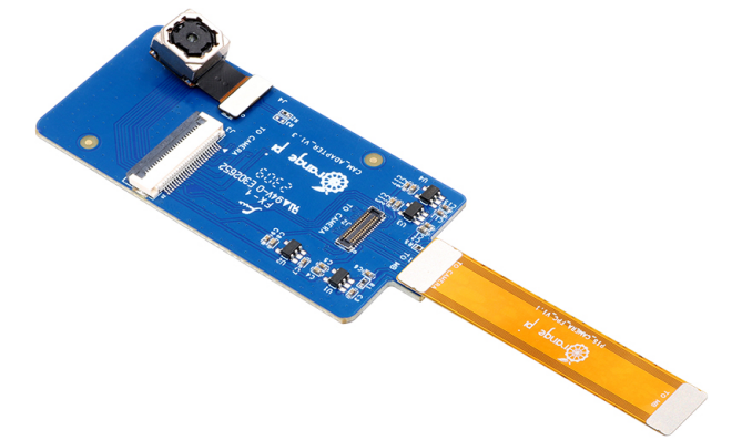
| Camera | 1 x MIPI CSI 4 Lane |
| Audio | • 1 x 3.5mm headphone jack audio input/output
• 1 x onboard MIC input • 2 x HDMI output • 1 x HDMI input • 1 x DP output • 1 x speaker output (2pin, 1.25mm specification) |
| Ethernet | 2 x PCIe 2.5G Ethernet ports (RTL8125BG ) |
| 40pin expansion port | Used to expand UART, I2C, SPI, CAN, PWM, GPIO interfaces |
| PCIe M.2 M-KEY | PCIe 3.0 x 4 lanes, used to connect 2280 NVMe SSD solid state drive |
| PCIe M.2 E-KEY | Contains PCIe 2.0 x 1/PCM/UART/USB2.0 interface, supports 2230 Wi-Fi6 /BT module |
| Button | 1 MaskROM key, 1 RECOVERY key, 1 power on/off key |
| Powered supply | Support Type-C power supply, 5V@4A |
| Infrared receiver | 1 x infrared receiver |
| LED | RGB LED three-color indicator light |
| Fan interface | 2pin, 1.25mm specification, used to connect 5V fan, support PWM control switch and speed |
| RTC battery interface | 2pin, 1.25mm specification, used to power the RTC module |
| Debugging | 3pin debug serial port (UART) |
| Supported OS | Orangepi OS(Droid)、Orangepi OS(Arch)、Orangepi OS(OH)、Ub untu20.04、Ubuntu22.04、Debian11、Debian12、OpenWRT and Android12 |
Introduction of Appearance Specifications
| |
| Product Size | 100mm*75mm |
| Weight | 86.5g |
Top view and bottom view of Orange Pi 5 Plus
Top view:

Bottom view:

Interface details of Orange Pi 5 Plus


Introduction to the use of the development board
Prepare the required accessories
- TF card, a class 10 or above high-speed SanDisk card with a minimum capacity of 16GB (32GB or above is recommended)

- TF card reader, used to burn the image into the TF card

- Display with HDMI interface

- HDMI to HDMI cable, used to connect the development board to an HDMI monitor or TV for display

|
Note, if you want to connect a 4K or 8K display, please make sure that the HDMI cable supports 4K or 8K video display. |
- Type-C to HDMI cable, connect the development board to an HDMI monitor or TV for display through the Type-C interface

- Type-C to USB adapter, used to connect USB devices such as USB storage devices or mouse keyboards through the Type-C interface (there are 2 USB3.0 HOST interfaces and 2 USB2.0 HOST interfaces on the development board, this accessory generally not used)

- 10.1-inch MIPI screen, used to display the system interface of the development board (this screen is common to OPi5/OPi5B)

- Power adapter, Orange Pi 5 Plus is recommended to use 5V/4A Type-C power supply for power supply

|
There are two Type-C ports that look the same on the development board. The one next to the network port is the power port, and the other Type-C port has no power supply function. Please don't connect it wrong.  The Type-C power interface of the development board does not support the PD negotiation function, and only supports a fixed 5V voltage input. |
- The mouse and keyboard of the USB interface, as long as the mouse and keyboard of the standard USB interface are acceptable, the mouse and keyboard can be used to control the Orange Pi development board

- USB camera

- 5V cooling fan. As shown in the figure below, the development board has an interface for connecting the cooling fan, and the interface specification is 2pin 1.25mm pitch
|
The fan on the development board can adjust the speed and switch through PWM. |

- Network cable, used to connect the development board to the Internet

- The data cable of the Type-C interface, used for burning images, using ADB and other functions

- Infrared remote control

|
Note that the remote control of the air conditioner or the TV cannot control the Orange Pi development board. The operating system provided by Orange Pi can only ensure that the remote control provided by Orange Pi can be used by default. |
OV13850 camera with 13 million MIPI interface (common with OPi5/OPi5B)

OV13855 camera with 13 million MIPI interface (common with OPi5/OPi5B)
M.2 M-KEY 2280 specification NVMe SSD solid state drive, PCIe interface specification is PCIe3.0x4


- eMMC expansion module (to be added physical pictures)
|
The position where the eMMC module is inserted on the development board is shown in the figure below:  |
RTC battery, the interface is 2pin, 1.25mm pitch


|
The location of the RTC battery interface on the development board is shown in the figure below:  |
- Horn, the interface is 2pin, 1.25mm pitch

|
The interface position of the speaker on the development board is shown in the figure below:  |
Matching shell (pictures and assembly methods to be added)
3.3V USB to TTL module and DuPont line, when using serial port debugging function, need USB to TTL module and DuPont line to connect the development board and computer


- Personal computer with Ubuntu and Windows operating systems installed
| 1 | Ubuntu22.04 PC | Optional, used to compile Linux source code |
| 2 | Windows PC | For burning Android and Linux images |
- The website for downloading the English version of materials is:

The information mainly includes
User Manual and Schematic: Saved on Google Cloud Disk
Official tools: mainly include the software that needs to be used during the use of the development board
Android source code: saved on Google Cloud Disk
Linux source code: saved on Github
OpenWRT source code: saved on Github
Android image: saved on Google Cloud Disk
Ubuntu image:saved on Google Cloud Disk
Debian image:saved on Google Cloud Disk
Orange Pi OS image:saved on Google Cloud Disk
OpenWRT image:saved on Google Cloud Disk
Method of burning Linux image to TF card based on Windows PC
|
Note that the Linux image mentioned here specifically refers to the image of Linux distributions such as Debian, Ubuntu, OpenWRT or OPi OS Arch downloaded from the Orange Pi's download page. |
How to use balenaEtcher to burn Linux image
- First prepare a TF card with a capacity of 16GB or more. The transmission speed of the TF card must be class 10 or above. It is recommended to use a TF card of SanDisk and other brands
- Then use the card reader to insert the TF card into the computer
- Download the Linux operating system image file compression package that you want to burn from the Orange Pi's download page, and then use the decompression software to decompress it. Among the decompressed files, the file ending with ".img" is the image file of the operating system. The size is generally above 2GB.
Note, if you download the OpenWRT image, you will see the following two types of images in the download link of the OpenWRT image, please download the image file in the "TF card, eMMC and NVME SSD boot image" folder.
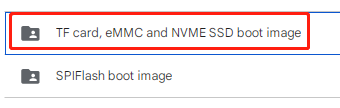
- Then download the burning software of Linux image——balenaEtcher, the download address is:
After entering the balenaEtcher download page, click the green download button to jump to the place where the software is downloaded

Then you can choose to download the Portable version of balenaEtcher software. The Portable version does not need to be installed, and you can use it by double-clicking to open it

- If the downloaded version of balenaEtcher needs to be installed, please install it before using it. If you downloaded the Portable version of balenaEtcher, just double-click to open it. The balenaEtcher interface after opening is shown in the figure below:

|
When opening balenaEtcher, if the following error is prompted:  Please select balenaEtcher, right-click, and select Run as administrator.  |
- The specific steps to use balenaEtcher to burn the Linux image are as follows
a. First select the path of the Linux image file to be burned
b. Then select the drive letter of the TF card
c. Finally click Flash to start burning the Linux image to the TF card

- The interface displayed in the process of burning the Linux image by balenaEtcher is shown in the figure below, and the progress bar displays purple, indicating that the Linux image is being burned into the TF card.

- After burning the Linux image, balenaEtcher will also verify the image burned to the TF card by default to ensure that there is no problem in the burning process. As shown in the figure below, a green progress bar indicates that the image has been burnt, and balenaEtcher is verifying the burnt image.

- After successful burning, the display interface of balenaEtcher is as shown in the figure below. If the green indicator icon is displayed, it means that the image burning is successful. At this time, you can exit balenaEtcher, and then pull out the TF card and insert it into the TF card slot of the development board.

How to use RKDevTool to burn Linux image to TF card
- First, you need to prepare a data cable with a good quality Type-C interface
You also need to prepare a 16GB or larger TF card. The transmission speed of the TF card must be class 10 or above. It is recommended to use a TF card of SanDisk and other brands
Then insert the TF card into the card slot of the development board

Then download Rockchip DriverAssitant_v5.12.zip and MiniLoader and the burning tool RKDevTool_Release_v2.96.zip RKDevTool_Release_v3.15.zip from the Orange Pi's download page, please ensure that the version of the downloaded RKDevTool tool is v2.96
- On the Orange Pi's download page, first select the official tool, and then enter the following folder.
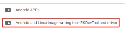
- Then download all the files below
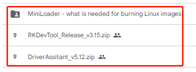
Note that the "MiniLoader-things needed to burn the Linux image" folder is hereinafter referred to as the MiniLoader folder.


- Then download the Linux operating system image file compression package that you want to burn from the Orange Pi's download page, and then use the decompression software to decompress it. Among the decompressed files, the file ending with ".img" is the image file of the operating system , the size is generally more than 2GB
|
Note, if you download the OpenWRT image, you will see the following two types of images in the download link of the OpenWRT image, please download the image file in the "TF card, eMMC and NVME SSD boot image" folder.  |
- Then use decompression software to decompress DriverAssitant_v5.12.zip, and then find the DriverInstall.exe executable file in the decompressed folder and open it

After opening DriverInstall.exe, the steps to install the Rockchip driver are as follows
- Click the "Driver Installation" button
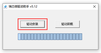
- After waiting for a period of time, a pop-up window will prompt "driver installed successfully", and then click the "OK" button.
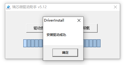


- Then decompress RKDevTool_Release_v2.96.zipRKDevTool_Release_v3.15.zip, this software does not need to be installed, just find RKDevTool in the decompressed folder and open it

- After opening the RKDevTool burning tool, because the computer has not been connected to the development board through the Type-C cable at this time, the lower left corner will prompt "No device found"

Then start burning the Linux image to the TF card
- First, connect the development board to the Windows computer through the Type-C data cable. The position of the Type-C interface on the development board is shown in the figure below

Make sure the development board is not connected to the Type-C power supply
Then press and hold the MaskROM button on the development board, the position of the MaskROM button on the development board is shown in the figure below:
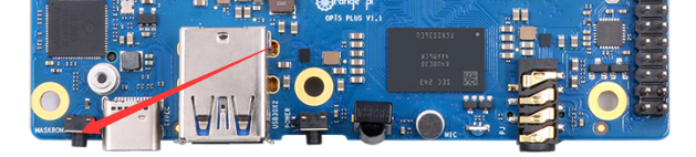
- Finally, connect the power supply of the Type-C interface to the development board, and power on, and then release the MaskROM button. The location of the Type-C power interface is as follows:
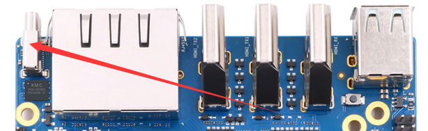
- If the previous steps are successful, the development board will enter the MASKROM mode at this time, and the interface of the burning tool will prompt "found a MASKROM device"
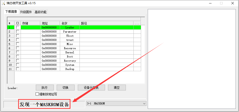
- Then place the mouse cursor in the area below
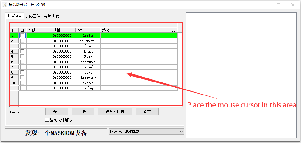
- Then click the right mouse button and the selection interface shown in the figure below will pop up
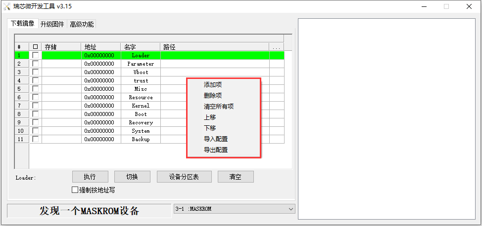
- Then select the import configuration option
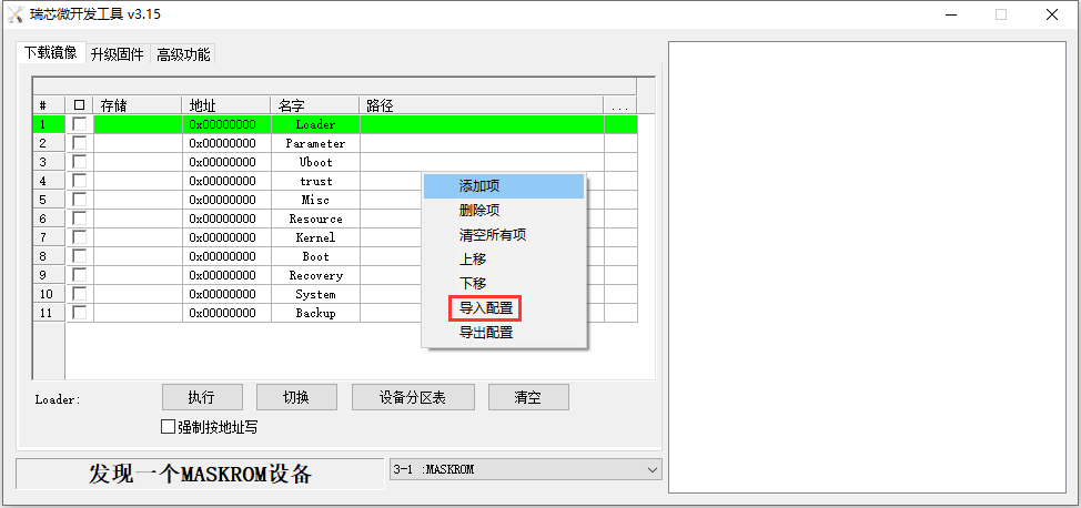
- Then select the rk3588_linux_tfcard.cfg configuration file in the MiniLoader folder downloaded earlier, and click Open
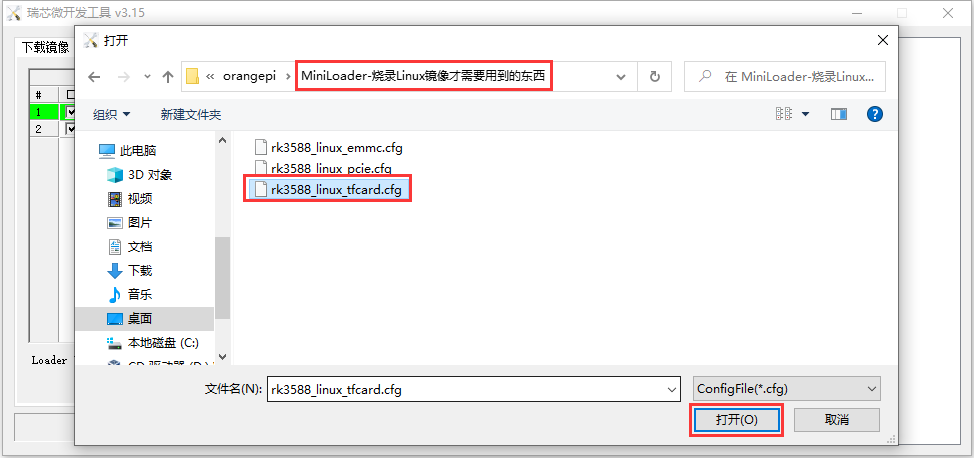
- Then click OK
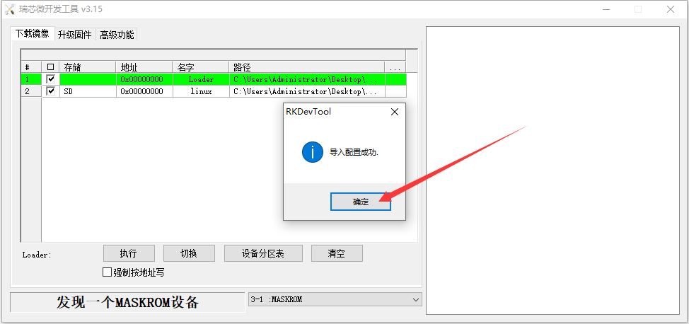
- Then click the position shown in the figure below
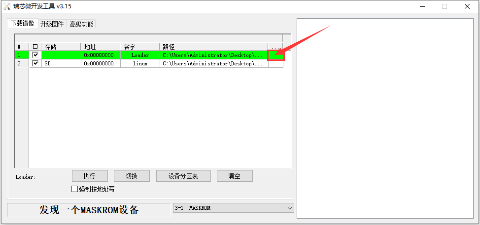
- Then select MiniLoaderAll.bin in the MiniLoader folder downloaded earlier, and then click to open
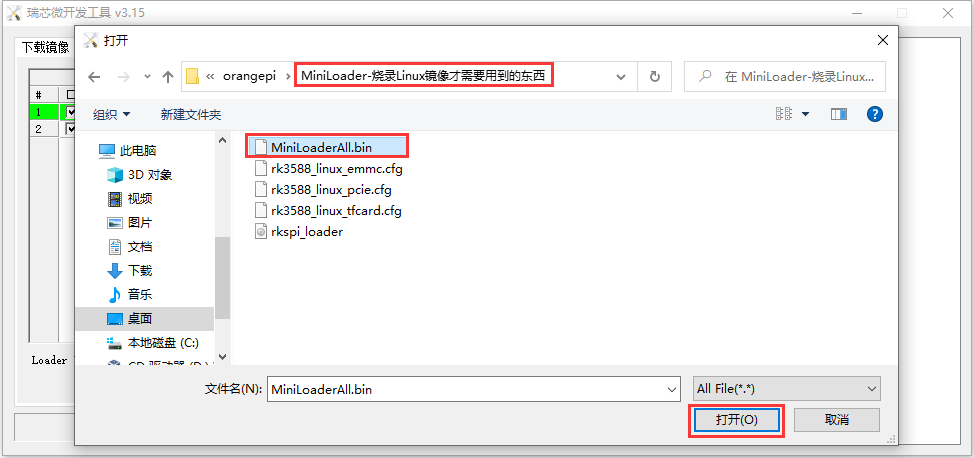
- Then click the position shown in the figure below
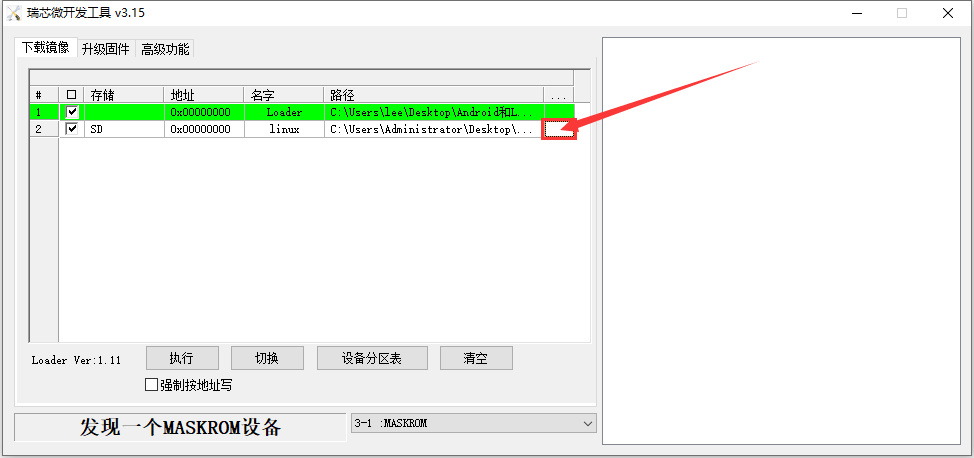
- Then select the path of the linux image you want to burn, and click Open
Before burning the image, it is recommended to rename the linux image to be burned to orangepi.img or other shorter names, so that you can see the percentage value of the burning progress when burning the image.
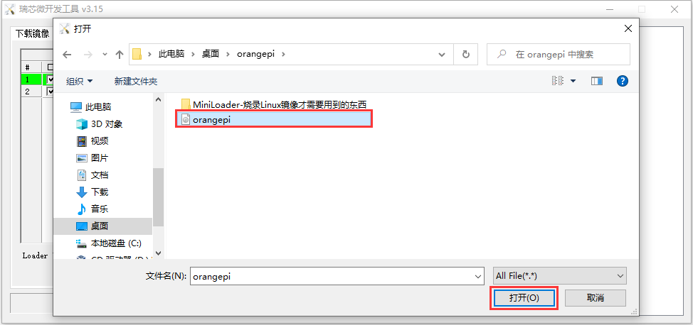
- Then please check the option to force writing by address
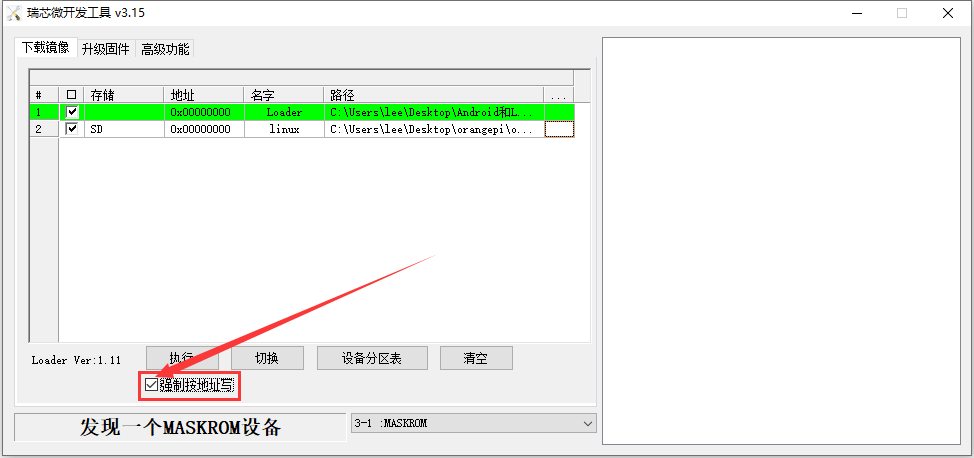
- Then click the execute button to start burning the linux image to the tf card of the development board

- The log displayed after burning the linux image is shown in the figure below
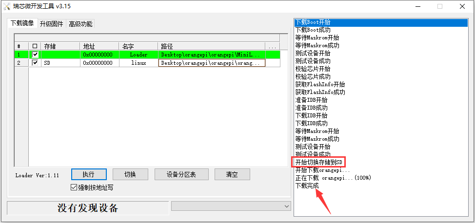
- After burning the linux image to the TF card, the linux system will start automatically.


How to use Win32Diskimager to burn Linux image
First prepare a TF card with a capacity of 16GB or more. The transmission speed of the TF card must be class 10 or above. It is recommended to use a TF card of SanDisk and other brands
Then use the card reader to insert the TF card into the computer
Then format the TF card
- SD Card Formatter can be used to format the TF card. The download link is
https://www.sdcard.org/downloads/formatter/eula_windows/SDCardFormatterv5_WinEN.zip
After downloading, unzip and install directly, and then open the software
If only a TF card is inserted into the computer, the drive letter of the TF card will be displayed in the "Select card" column. If multiple USB storage devices are inserted into the computer, you can select the corresponding drive letter of the TF card through the drop-down box
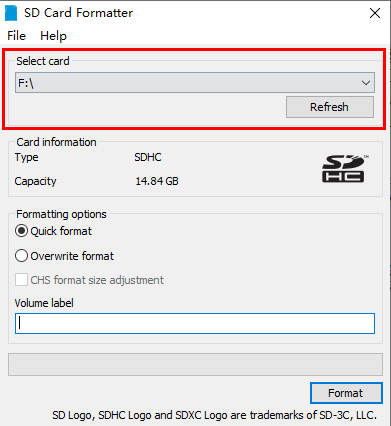
- Then click "Format", a warning box will pop up before formatting, and formatting will start after selecting "Yes (Y)"
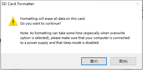
- After formatting the TF card, the message shown in the figure below will pop up, click OK
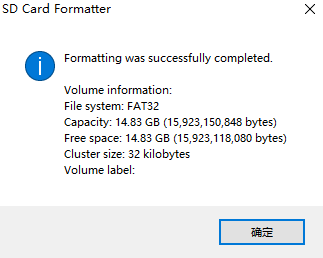


- Download the image file compression package of the Linux operating system that you want to burn from the Orange Pi's download page, and then use the decompression software to decompress it. Among the decompressed files, the file ending with ".img" is the image file of the operating system. The size is generally more than 2GB
|
Note, if you download the OpenWRT image, you will see the following two types of images in the download link of the OpenWRT image, please download the image file in the "TF card, eMMC and NVME SSD boot image" folder. |
- Use Win32Diskimager to burn the Linux image to the TF card
- The download page of Win32Diskimager is
- After downloading, install it directly. The interface of Win32Diskimager is as follows
After the image writing is completed, click the " Exit " button to exit, and then you can pull out the TF card and insert it into the development board to start
|
http://sourceforge.net/projects/win32diskimager/files/Archive/ |
a) First select the path of the image file
b) Then confirm that the drive letter of the TF card is consistent with that
displayed in the "Device" column
c) Finally click "Write" to start burning

Method of burning Linux image to TF card based on Ubuntu PC
|
Note that the Linux image mentioned here specifically refers to the image of Linux distributions such as Debian, Ubuntu, OpenWRT or OPi OS Arch downloaded from the Orange Pi's download page, and the Ubuntu PC refers to the personal computer with the Ubuntu system installed. |
- First prepare a TF card with a capacity of 16GB or more. The transmission speed of the TF card must be class 10 or above. It is recommended to use a TF card of SanDisk and other brands
- Then use the card reader to insert the TF card into the computer
- Download the balenaEtcher software, the download address is
- After entering the balenaEtcher download page, click the green download button to jump to the place where the software is downloaded

- Then choose to download the Linux version of the software

- Download the Linux operating system image file compression package that you want to burn from the Orange Pi's download page, and then use the decompression software to decompress it. Among the decompressed files, the file ending with ".img" is the image file of the operating system. The size is generally more than 2GB
|
Note, if you download the OpenWRT image, you will see the following two types of images in the download link of the OpenWRT image, please download the image file in the "TF card, eMMC and NVME SSD boot image" folder.  |
The decompression command for the compressed package ending in 7z is as follows:
|
test@test:~$ 7z x orangepi5plus_1.0.0_debian_bullseye_desktop_xfce_linux5.10.110.7z test@test:~$ ls orangepi5plus_1.0.0_debian_bullseye_desktop_xfce_linux5.10.110.* orangepi5plus_1.0.0_debian_bullseye_desktop_xfce_linux5.10.110.7z orangepi5plus_1.0.0_debian_bullseye_desktop_xfce_linux5.10.110.sha # checksum file orangepi5plus_1.0.0_debian_bullseye_desktop_xfce_linux5.10.110.img # mirror file |
If you download the OpenWRT image, the compressed package ends with gz, and the decompression command is as follows:
|
test@test:~$ gunzip openwrt-aarch64-opi5plus-23.05-linux-5.10.110-ext4.img.gz test@test:~$ ls openwrt-aarch64-opi5plus-23.05-linux-5.10.110-ext4.img openwrt-aarch64-opi5plus-23.05-linux-5.10.110-ext4.img # mirror file |
- After decompressing the image, you can first use the sha256sum -c *.sha.sha command to calculate whether the checksum is correct. If the prompt is successful, it means that the downloaded image is correct, and you can safely burn it to the TF card. If it prompts that the checksum does not match, it means There is a problem with the downloaded image, please try to download again
|
test@test:~$ sha256sum -c *.sha orangepi5plus_1.0.0_debian_bullseye_desktop_xfce_linux5.10.110.img: OK |
If you download the OpenWRT image, you need to verify the compressed package, do not decompress it and then verify it
|
test@test:~$ sha256sum -c openwrt-aarch64-opi5plus-23.04-linux-5.10.110-ext4.img.gz.sha openwrt-aarch64-opi5plus-23.04-linux-5.10.110-ext4.img.gz: OK |
- Then double-click balenaEtcher-1.14.3-x64.AppImage on the graphical interface of Ubuntu PC to open balenaEtcher (no installation required), and the interface after balenaEtcher is opened is shown in the figure below

- The specific steps to use balenaEtcher to burn the Linux image are as follows
a. First select the path of the Linux image file to be burned
b. Then select the drive letter of the TF card
c. Finally click Flash to start burning the Linux image to the TF card
- The interface displayed in the process of burning the Linux image by balenaEtcher is shown in the figure below, and the progress bar displays purple, indicating that the Linux image is being burned into the TF card

- After burning the Linux image, balenaEtcher will also verify the image burned into the TF card by default to ensure that there is no problem in the burning process. As shown in the figure below, a green progress bar indicates that the image has been burnt, and balenaEtcher is verifying the burnt image

After successful burning, the display interface of balenaEtcher is as shown in the figure below. If a green indicator icon is displayed, it means that the image burning is successful. At this time, you can exit balenaEtcher, and then pull out the TF card and insert it into the TF card slot of the development board for use.
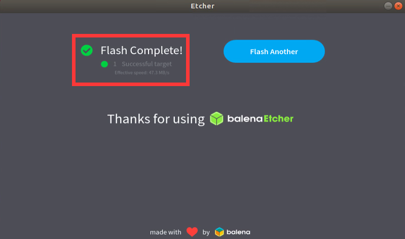

How to burn Linux image to eMMC
|
Note, after burning the image into eMMC, if the test finds that it cannot be started, please clear the SPIFlash and try again. For the method of clearing SPIFlash, please refer to the method of using RKDevTool to clear SPIFlash. |
How to use RKDevTool to burn Linux image into eMMC
|
Note that all the following operations are performed on a Windows computer. |
|
Note that the Linux image mentioned here specifically refers to the image of Linux distributions such as Debian, Ubuntu, OpenWRT or OPi OS Arch downloaded from the Orange Pi's download page |
- The development board reserves the expansion interface of the eMMC module. Before programming the system to the eMMC, you first need to purchase an eMMC module that matches the eMMC interface of the development board. Then install the eMMC module to the development board. The location of the eMMC interface is as follows:


- It is also necessary to prepare a data cable with a good quality Type-C interface
Then download Rockchip DriverAssitant_v5.12.zip and MiniLoader and the burning tool RKDevTool_Release_v2.96.zipRKDevTool_Release_v3.15.zip from the Orange Pi's download page, please make sure that the version of the downloaded RKDevTool tool is v2.96.
- On the download page of Orange Pi, first select the official tool, and then enter the following folder
- Then download all the files below
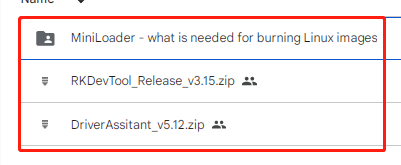
Note that the "MiniLoader-things needed to burn the Linux image" folder is hereinafter referred to as the MiniLoader folder.


- Then download the Linux operating system image file compression package that you want to burn from the Orange Pi's download page, and then use the decompression software to decompress it. Among the decompressed files, the file ending with ".img" is the image file of the operating system , the size is generally more than 2GB
|
Note, if you download the OpenWRT image, you will see the following two types of images in the download link of the OpenWRT image, please download the image file in the "TF card, eMMC and NVME SSD boot image" folder. |
- Then use decompression software to decompress DriverAssitant_v5.12.zip, and then find the DriverInstall.exe executable file in the decompressed folder and open it
After opening DriverInstall.exe, the steps to install the Rockchip driver are as follows
- Click the "Driver Installation" button
- After waiting for a period of time, a pop-up window will prompt "driver installed successfully", and then click the "OK" button.
- Then decompress RKDevTool_Release_v3.15.zip, this software does not need to be installed, just find RKDevTool in the decompressed folder and open it
- After opening the RKDevTool burning tool, because the computer has not been connected to the development board through the Type-C cable at this time, the lower left corner will prompt "No device found"
Then start burning the Linux image into eMMC
- First, connect the development board to the Windows computer through the Type-C data cable. The position of the Type-C interface on the development board is shown in the figure below
Make sure that the development board is not inserted into the TF card and not connected to the power supply
Then press and hold the MaskROM button on the development board, the position of the MaskROM button on the development board is shown in the figure below:
- Then connect the power supply of the Type-C interface to the development board, and power on, and then release the MaskROM button
- If the previous steps are successful, the development board will enter the MASKROM mode at this time, and the interface of the burning tool will prompt "found a MASKROM device"
- Then place the mouse cursor in the area below
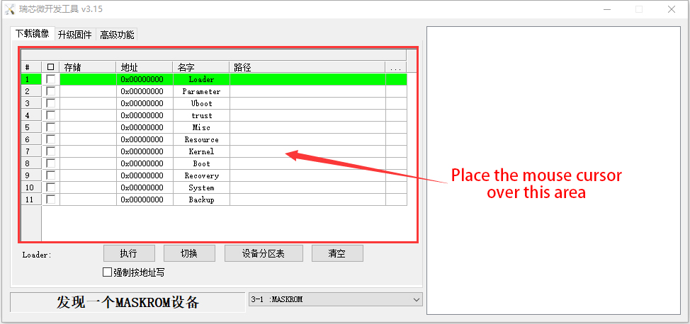
- Then click the right mouse button and the selection interface shown in the figure below will pop up
- Then select the import configuration option
- Then select the rk3588_linux_emmc.cfg configuration file in the MiniLoader folder downloaded earlier, and click Open
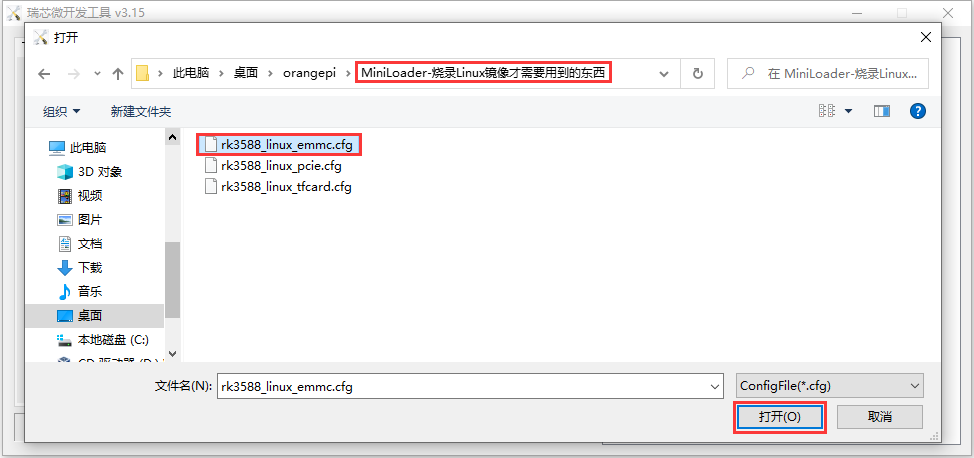
- Then click OK
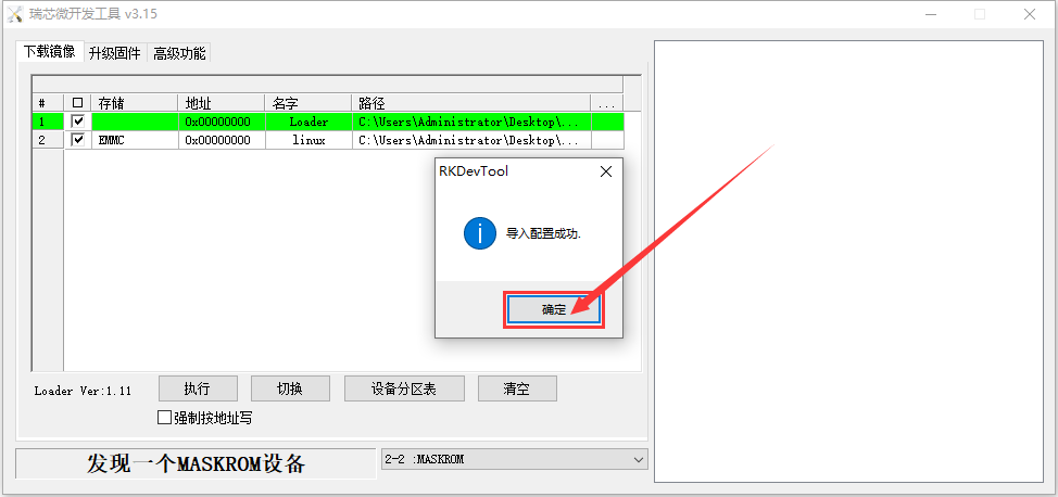
- Then click the position shown in the figure below
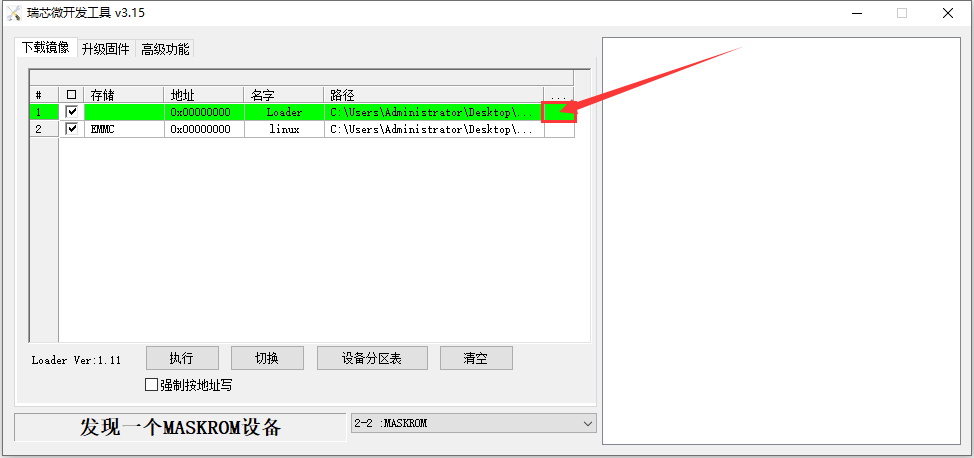
- Then select MiniLoaderAll.bin in the MiniLoader folder downloaded earlier, and then click to open
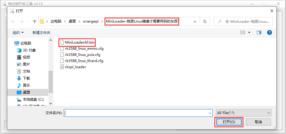
- Then click the position shown in the figure below
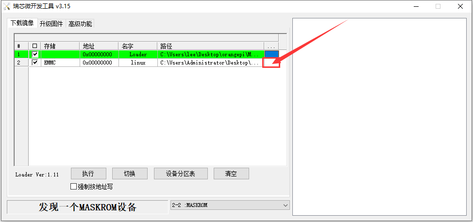
- Then select the path of the linux image you want to burn, and click Open
Before burning the image, it is recommended to rename the linux image to be burned to orangepi.img or other shorter names, so that you can see the percentage value of the burning progress when burning the image.
- Then please check the option to force writing by address
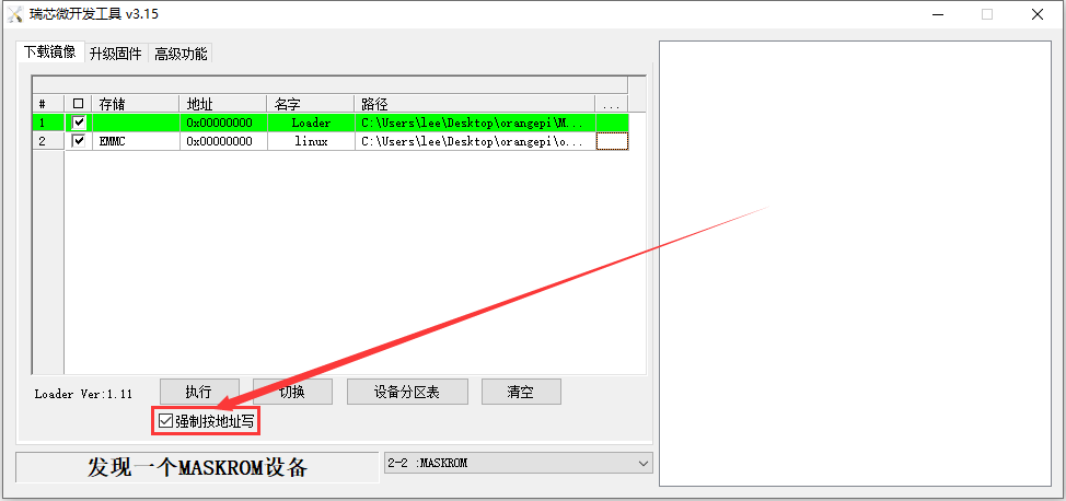
- Then click the execute button to start burning the linux image to the eMMC of the development board
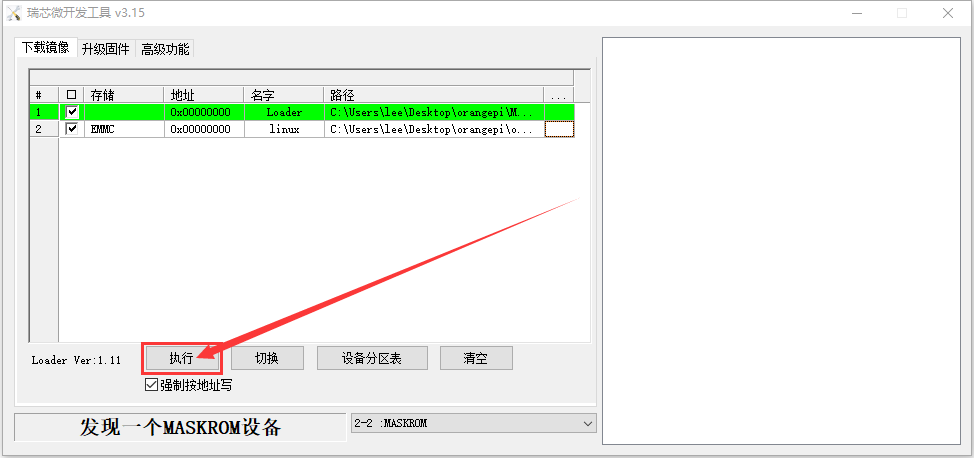
- The log displayed after burning the linux image is shown in the figure below
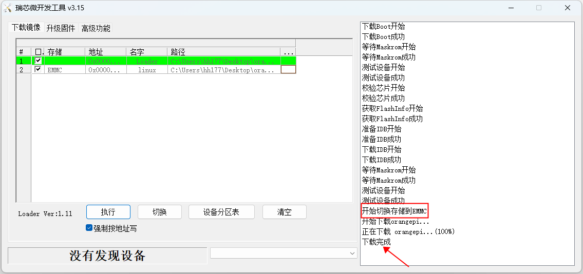
- After burning the linux image into the eMMC, the linux system will start automatically.
Note, after burning the image into eMMC, if the test finds that it cannot be started, please clear the SPIFlash and try again. For the method of clearing SPIFlash, please refer to the method of using RKDevTool to clear SPIFlash.


Using the dd command to burn the Linux image into eMMC
|
Note that the Linux image mentioned here specifically refers to the image of Linux distributions such as Debian, Ubuntu, OpenWRT or OPi OS Arch downloaded from the Orange Pi's download page. |
- The development board reserves the expansion interface of the eMMC module. Before programming the system to the eMMC, you first need to purchase an eMMC module that matches the eMMC interface of the development board. Then install the eMMC module to the development board. The location of the eMMC interface is as follows:
Using the dd command to burn the linux image to eMMC needs to be done with a TF card, so first you need to burn the linux image to the TF card, and then use the TF card to start the development board to enter the linux system. For the method of burning the Linux image to the TF card, please refer to the instructions in the two sections of the method of burning the Linux image to the TF card based on the Windows PC and the method of burning the Linux image to the TF card based on the Ubuntu PC.
After using the TF card to start the linux system, we first upload the decompressed linux image file (Debian, Ubuntu image or OPi Arch image downloaded from the official website) to the TF card. For the method of uploading the linux image file to the development board, please refer to the description in the section of the method of uploading files to the development board Linux system.
After uploading the image to the linux system of the development board, we enter the storage path of the image file in the command line of the linux system of the development board. For example, I store the linux image of the development board in the /home/orangepi/Desktop directory Download it, and then enter the /home/orangepi/Desktop directory to see the uploaded image file.
|
orangepi@orangepi:~$ cd /home/orangepi/Desktop orangepi@orangepi:~/Desktop$ ls Orangepi5plus_x.x.x_debian_bullseye_desktop_xfce_linux5.10.110.img |
|
How to enter the command line of the development board linux system? 1. For the method of using the serial port to log in to the terminal, please refer to the instructions in the section on how to use the debugging serial port. 2. Use ssh to remotely log in to the Linux system, please refer to the instructions in the section of SSH remote login to the development board. 3. If a display screen such as HDMI or LCD is connected, you can open a command line terminal on the desktop. |
- Next, we first use the following command to confirm the device node of eMMC
|
orangepi@orangepi:~/Desktop$ ls /dev/mmcblk*boot0 | cut -c1-12 /dev/mmcblk1 |
- Then we can use the dd command to clear the eMMC. Note that after the of= parameter, please fill in the output result of the above command
|
orangepi@orangepi:~/Desktop$ sudo dd bs=1M if=/dev/zero of=/dev/mmcblk1 count=1000 status=progress orangepi@orangepi:~/Desktop$ sudo sync |
Then you can use the dd command to burn the linux image of the development board into the eMMC
In the following command, the if= parameter is followed by the full path where the linux image is stored + the name of the Linux image (such as the name of /home/orangepi/Desktop/Linux image). Because we have entered the path of the linux image above, we only need to fill in the name of the Linux image.
Please do not copy the linux image name in the following command, but replace it with the actual image name (because the version number of the image may be updated).
sudo dd bs=1M if=Orangepi5plus_x.x.x_debian_bullseye_desktop_xfce_linux5.10.110.img of=/dev/mmcblk1 status=progress
sudo sync
Note, if you upload a .7z or .xz linux image compressed file, please remember to decompress it before using the dd command to burn.
The detailed description of all parameters of the dd command and more usage can be viewed by executing the man dd command in the linux system.
- After successfully burning the linux image of the development board to the eMMC, you can use the poweroff command to shut down. Then please pull out the TF card, and then short press the power button to turn on, and then the linux system in the eMMC will be started.
How to burn Linux image to SPIFlash+NVMe SSD
|
Note that the Linux image mentioned here specifically refers to the image of Linux distributions such as Debian, Ubuntu, OpenWRT or OPi OS Arch downloaded from the Orange Pi's download page. |
|
Note that all the following operations are performed on a Windows computer. |
The method of using the dd command to burn
- First, you need to prepare an M-Key 2280 specification NVMe SSD solid state drive, and the specification of the PCIe interface in the M.2 slot of the development board is PCIe3.0x4.
- Then insert the NVMe SSD into the M.2 PCIe interface of the development board shown in the figure below, and fix it

- The position of the SPI Flash on the development board is shown in the figure below, no other settings are required before starting the programming

Burning the linux image to SPIFlash+NVMe SSD needs to be done with a TF card, so first you need to burn the linux image to the TF card, and then use the TF card to start the development board to enter the linux system. For the method of burning the Linux image to the TF card, please refer to the instructions in the two sections of the method of burning the Linux image to the TF card based on the Windows PC and the method of burning the Linux image to the TF card based on the Ubuntu PC
After using the TF card to start the Linux system, we first burn the u-boot image into the SPI Flash
- Run nand-sata-install first, ordinary users remember to add sudo permission.
orangepi@orangepi:~$ sudo nand-sata-install
- Then select 7 Install/Update ther bootloader on SPI Flash
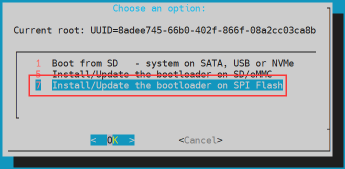
- Then select <Yes>
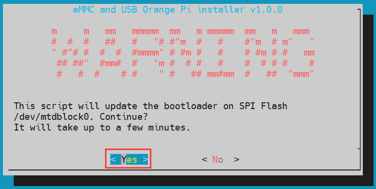
- Then please wait patiently for the burning to complete. After the burning is completed, the display will be as follows (a Done will be displayed in the lower left corner):
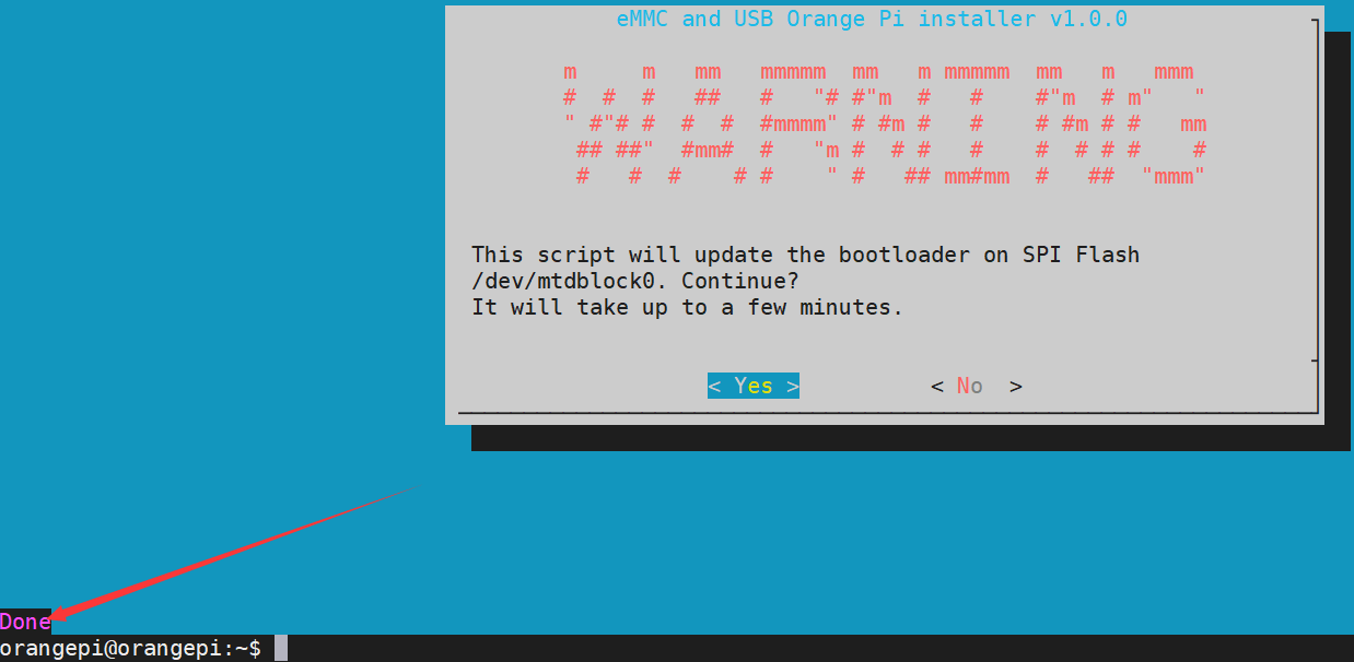
There is no nand-sata-install script in OPi OS Arch system, please use the following command to mirror u-boot to SPI Flash:
[orangepi@orangepi ~]$ sudo dd if=/boot/rkspi_loader.img of=/dev/mtdblock0


- Then upload the linux image file (Debian, Ubuntu or OpenWRT image downloaded from the official website) to the TF card. For the method of uploading the linux image file to the development board, please refer to the description in the section of the method of uploading files to the development board Linux system.
|
Note, if you download the OpenWRT image, you will see the following two types of images in the download link of the OpenWRT image, please download the image file in the "TF card, eMMC and NVME SSD boot image" folder. |
- After uploading the image to the linux system of the development board, we enter the storage path of the image file in the command line of the linux system of the development board. For example, I store the linux image of the development board in the /home/orangepi/Desktop directory Download it, and then enter the /home/orangepi/Desktop directory to see the uploaded image file.
|
orangepi@orangepi:~$ cd /home/orangepi/Desktop orangepi@orangepi:~/Desktop$ ls orangepi5plus_x.x.x_debian_bullseye_desktop_xfce_linux5.10.110.img |
|
How to enter the command line of the development board linux system? 1. For the method of using the serial port to log in to the terminal, please refer to the instructions in the section on how to use the debugging serial port. 2. Use ssh to remotely log in to the Linux system, please refer to the instructions in the section of SSH remote login to the development board. 3. If HDMI, LCD and other display screens are connected, you can open a command line terminal on the desktop. |
- Next, let's confirm that the NVMe SSD has been recognized by the development board's linux. If the NVMe SSD is recognized normally, use the sudo fdisk -l command to see nvme-related information
|
orangepi@orangepi:~/Desktop$ sudo fdisk -l | grep "nvme0n1" Disk /dev/nvme0n1: 1.86 TiB, 2048408248320 bytes, 4000797360 sectors |
Use the lspci command to see an NVMe-related PCI device
|
orangepi@orangepi:~$ lspci 0000:00:00.0 PCI bridge: Rockchip Electronics Co., Ltd Device 3588 (rev 01) 0000:01:00.0 Non-Volatile memory controller: SK hynix BC501 NVMe Solid State Drive .… |
- Then we can use the dd command to clear the NVMe SSD (optional)
|
orangepi@orangepi5plus:~/Desktop$ sudo dd bs=1M if=/dev/zero of=/dev/nvme0n1 count=2000 status=progress orangepi@orangepi5plus:~/Desktop$ sudo sync |
Then you can use the dd command to burn the linux image of the development board to the NVMe SSD
In the following command, the if= parameter is followed by the full path where the linux image is stored + the name of the Linux image (such as the name of /home/orangepi/Desktop/Linux image). Because we have entered the path of the linux image above, we only need to fill in the name of the Linux image.
Please do not copy the linux image name in the following command, but replace it with the actual image name (because the version number of the image may be updated).
sudo dd bs=1M if=orangepi5plus_x.x.x_debian_bullseye_desktop_xfce_linux5.10.110.img of=/dev/nvme0n1 status=progress
sudo sync
Note, if you upload a .7z or .xz or .gz linux image compressed file, please remember to decompress it before using the dd command to burn.
The detailed description of all parameters of the dd command and more usage can be viewed by executing the man dd command in the linux system.
- After successfully burning the linux image of the development board to the NVMe SSD, you can use the poweroff command to shut down. Then please pull out the TF card, and then short press the power button to turn on, then the linux system in SPIFlash+NVMe SSD will be started.
How to use balenaEtcher software to program
|
Please do not use this method for OPi OS Arch system and OpenWRT system. |
- First, you need to prepare an M-Key 2280 specification NVMe SSD solid state drive, and the specification of the PCIe interface in the M.2 slot of the development board is PCIe3.0x4.
- Then insert the NVMe SSD into the M.2 PCIe interface of the development board shown in the figure below, and fix it
- The position of the SPI Flash on the development board is shown in the figure below, no other settings are required before starting the programming
Burning the linux image to SPIFlash+NVMe SSD needs to be done with a TF card, so first you need to burn the linux image to the TF card, and then use the TF card to start the development board to enter the linux system. For the method of burning the Linux image to the TF card, please refer to the instructions in the two sections of the method of burning the Linux image to the TF card based on the Windows PC and the method of burning the Linux image to the TF card based on the Ubuntu PC.
After booting into the linux system in the TF card, please confirm that the NVMe SSD has been recognized by the linux system of the development board. If the NVMe SSD is recognized normally, use the sudo fdisk -l command to see nvme-related information
|
orangepi@orangepi:~/Desktop$ sudo fdisk -l | grep "nvme0n1" Disk /dev/nvme0n1: 1.86 TiB, 2048408248320 bytes, 4000797360 sectors |
Use the lspci command to see an NVMe-related PCI device
|
orangepi@orangepi:~$ lspci 0000:00:00.0 PCI bridge: Rockchip Electronics Co., Ltd Device 3588 (rev 01) 0000:01:00.0 Non-Volatile memory controller: SK hynix BC501 NVMe Solid State Drive .… |
- The balenaEtcher has been pre-installed in the linux image, and the opening method is as follows:

|
If it is not pre-installed, for how to download and install the arm64 version of balenaEtcher, please refer to the instructions in the section on how to download and install the arm64 version of balenaEtcher. |
- The interface after opening balenaEtcher is as follows:

The method of using balenaEtcher to burn u-boot to the SPI Flash of the development board is as follows:
- First click Flash from file
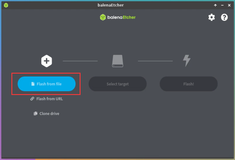
- Then enter the /usr/lib/linux-u-boot-legacy-orangepi5plus_1.x.x_arm64 directory, select rkspi_loader.img, and click Open to open
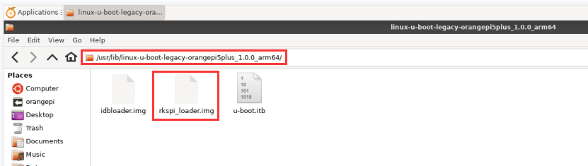
- The interface after opening rkspi_loader.img is as follows:
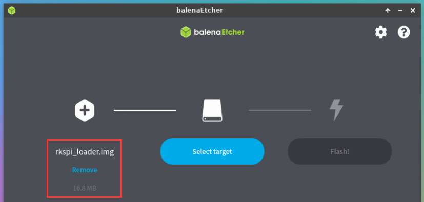
- Then click Select target
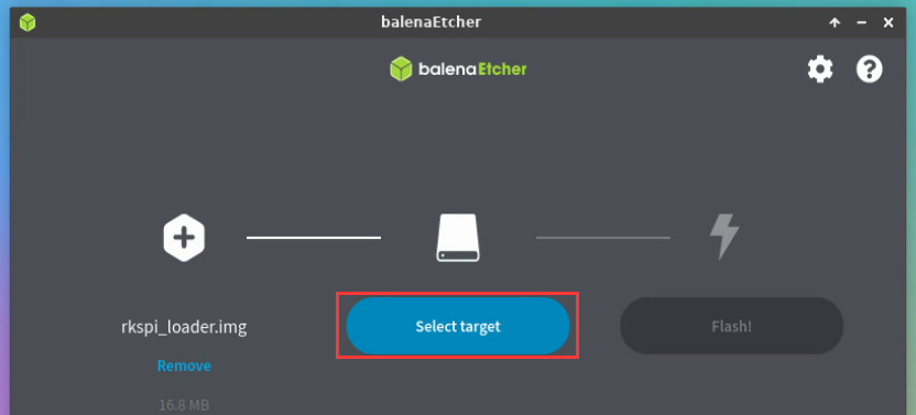
- Then click Show 2 hidden to open more options for storage devices
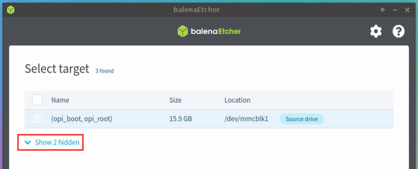
- Then select the device name of SPI Flash /dev/mtdblock0, and click Select
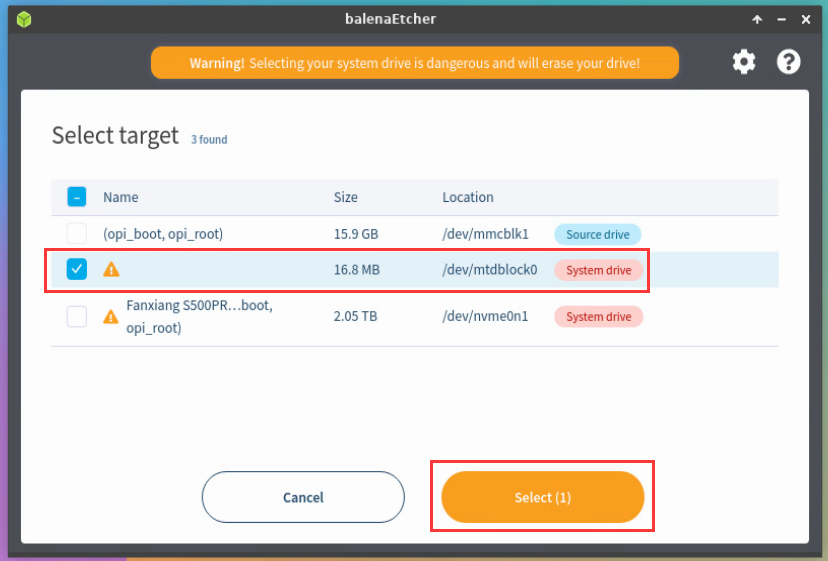
- Then click Flash
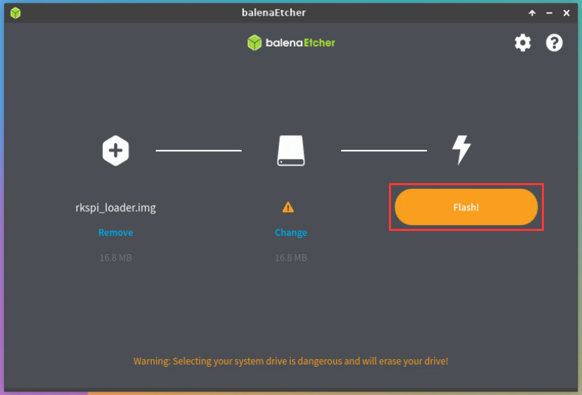
- Then click Yes, I’m sure
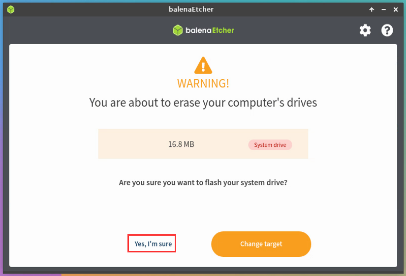
- Then enter the password orangepi of the development board linux system, and it will start burning the u-boot image into the SPI Flash
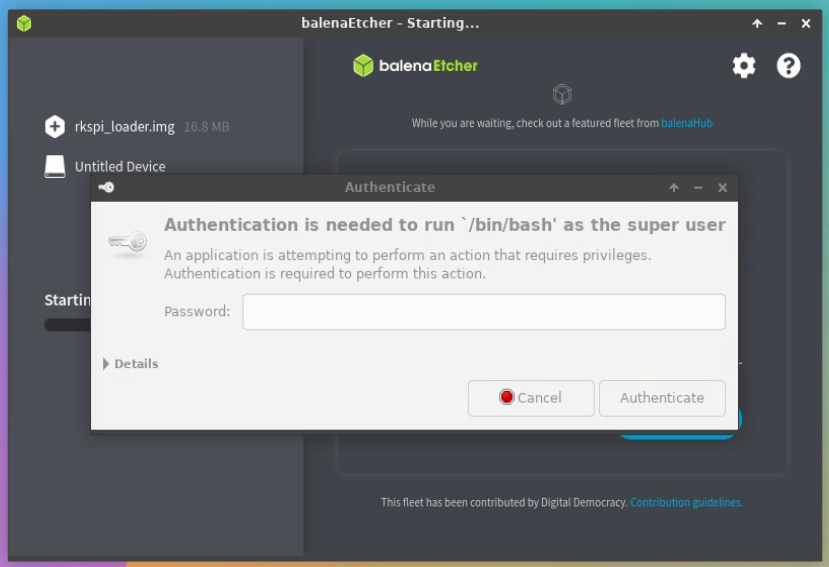
- The display of the burning process is as follows:
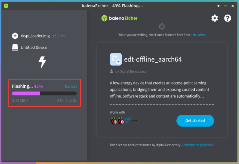
- After the burning is completed, the display is as follows:
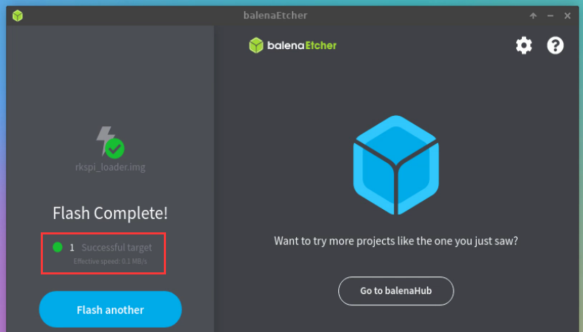


The method of burning the linux system in the TF card to the NVMe SSD (this method is equivalent to cloning the system in the TF card to the NVMe SSD)
- First click Clone drive
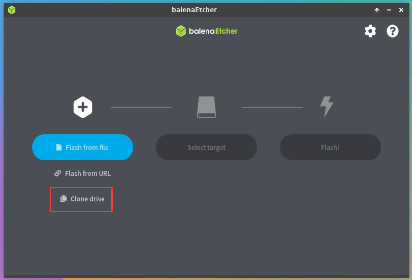
- Then select the device name of the TF card /dev/mmcblk1
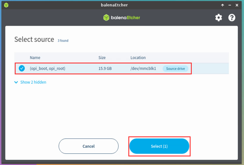
- The interface after opening the TF card is as follows:
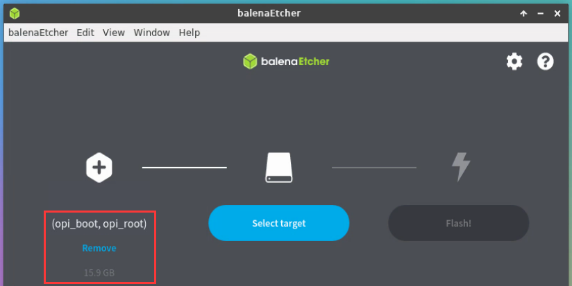
- Then click Select target
- Then click Show 2 hidden Option to open more storage devices
- Then select the device name of the NVMe SSD /dev/nvme0n1, and click Select
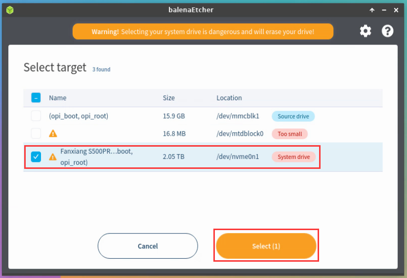
- Then click Flash
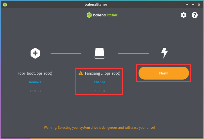
- Then click Yes, I’m sure
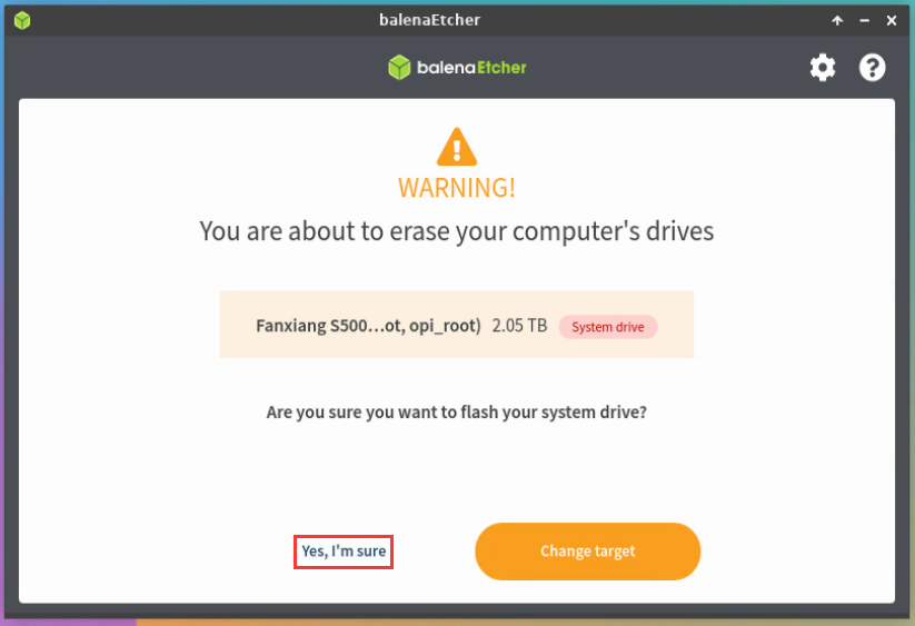
- Then enter the password orangepi of the linux system on the development board, and it will start burning the linux image to the SSD
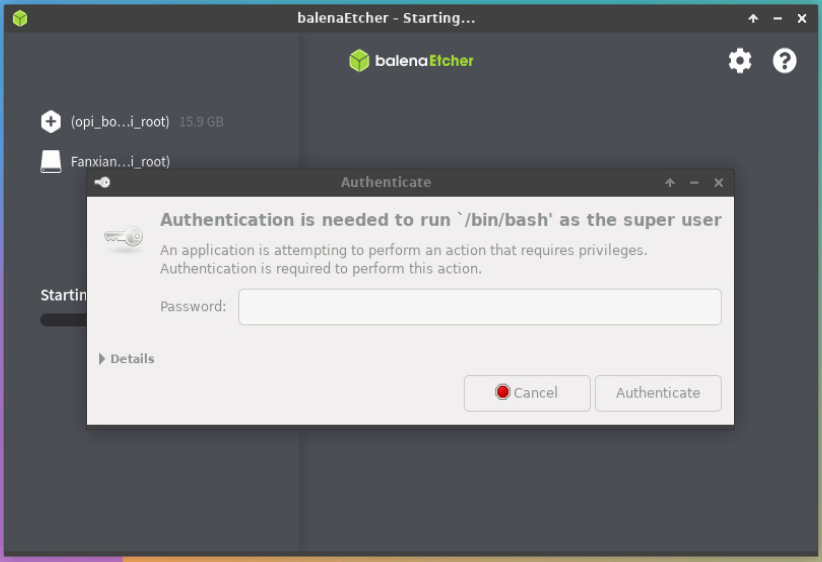
- The display of the burning process is as follows:
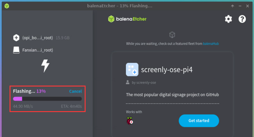
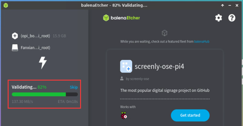
- After the burning is completed, the display is as follows:
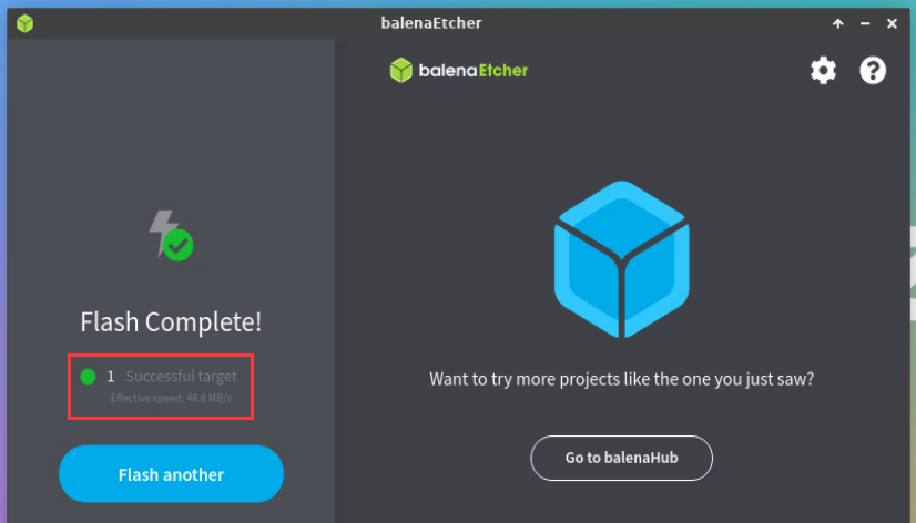
Then you need to expand the capacity of the rootfs partition in the NVMe SSD. The steps are as follows:
- a) open first GParted, if the system does not have Gparted pre-installed, please use the apt command to install it
orangepi@orangepi:~$ sudo apt-get install -y gparted

- b) Then enter the password orangepi of the linux system, and then click Authenticate
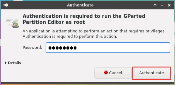
- c) Then click Fix
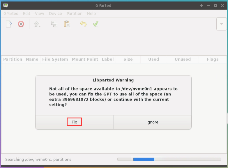
- d) Then select NVMe SSD
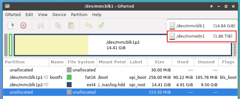
- e) The display interface after selecting NVMe SSD is as follows:
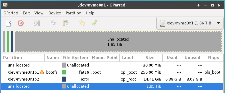
- f) Then select the /dev/nvme0n1p2 partition, then right-click, and then select Resize/Move
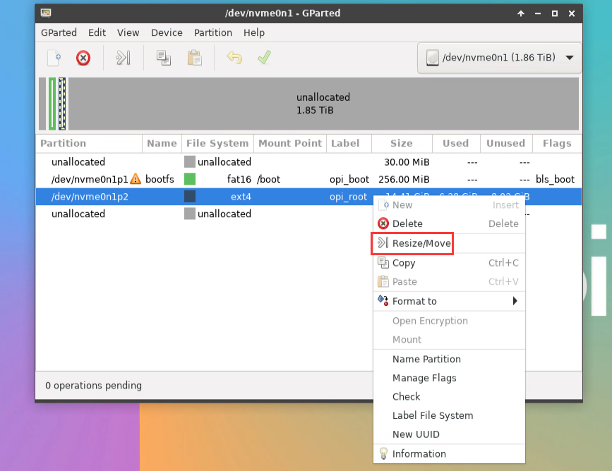
- g) Then drag the capacity to the maximum at the position shown in the figure below
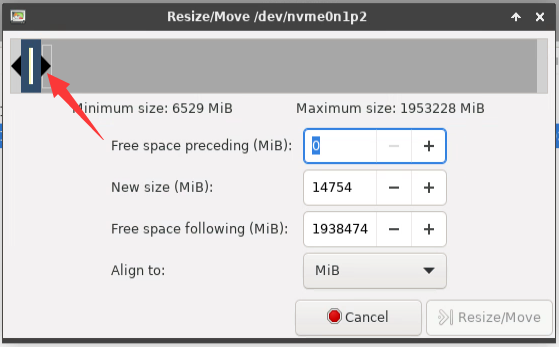
- h) and click Resize/Move
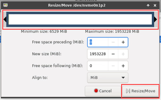
- i) Then click the green one in the picture below √
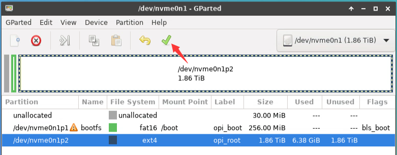
- j) Click again Apply
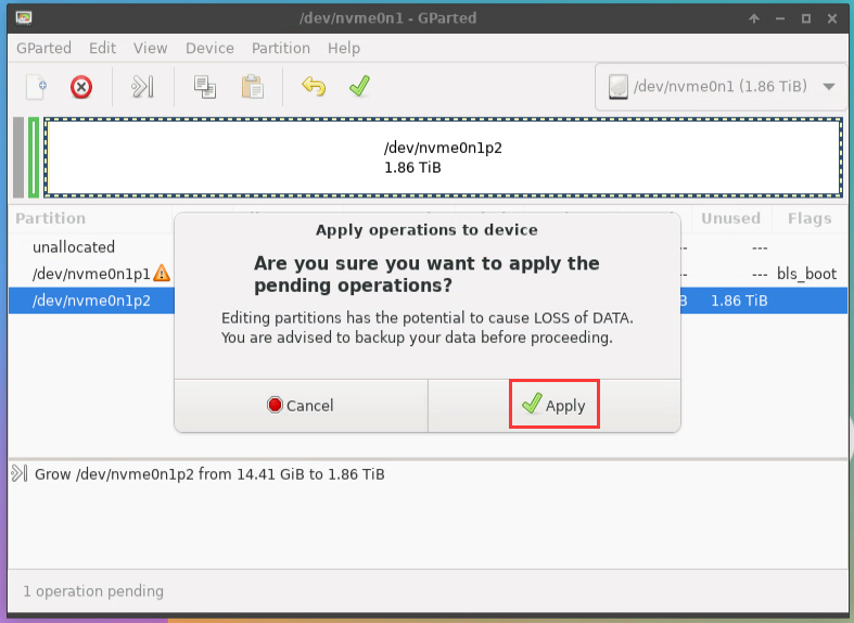
- k) Then click Close to close
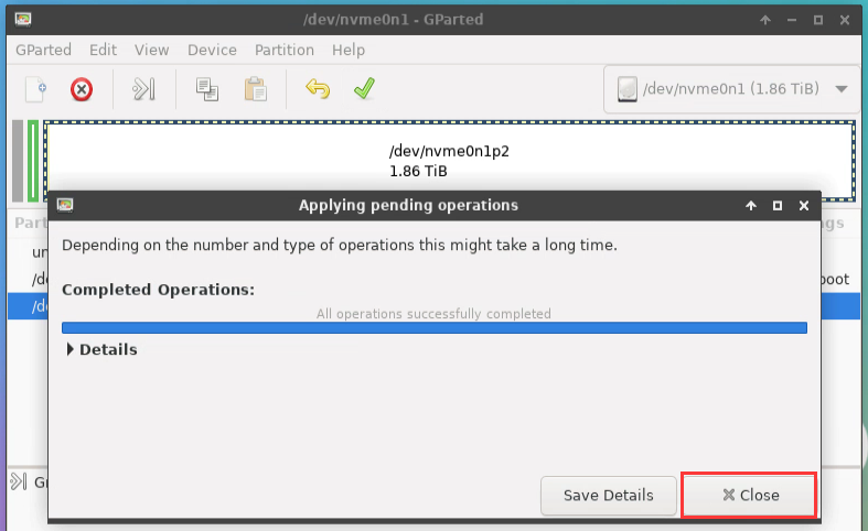
- At this point, you can use the sudo poweroff command to shut down. Then please pull out the TF card, and then short press the power button to turn on, then the linux system in SPIFlash+NVMe SSD will be started.


Step 9 is to clone the system in the TF card to the NMVe SSD. We can also directly burn the linux image file to the NVMe SSD. Here are the steps:
Upload the linux image file to the linux system of the development board
Then use balenaEtcher to burn
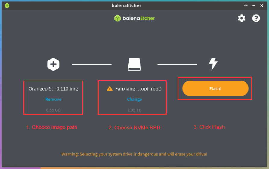
- c. After using this method to burn the image, there is no need to manually expand the capacity, and it will automatically expand the capacity at the first startup.

Using RKDevTool to burn
- First, you need to prepare an M-Key 2280 specification NVMe SSD solid state drive, and the specification of the PCIe interface in the M.2 slot of the development board is PCIe3.0x4.
- Then insert the NVMe SSD into the M.2 PCIe interface of the development board shown in the figure below, and fix it
- The position of the SPI Flash on the development board is shown in the figure below, no other settings are required before starting the programming
- Then you need to prepare a data cable with good quality Type-C interface
Then download the Rockchip driver DriverAssitant_v5.12.zip and MiniLoader and the burning tool RKDevTool_Release_v3.15.zip from the Orange Pi's download page
- On the download page of Orange Pi, first select the official tool, and then enter the following folder
- Then download all the files below
Note that the "MiniLoader-things needed to burn the Linux image" folder is hereinafter referred to as the MiniLoader folder.
- Then download the Linux operating system image file compression package that you want to burn from the Orange Pi's download page, and then use the decompression software to decompress it. Among the decompressed files, the file ending with ".img" is the image file of the operating system , the size is generally more than 2GB
|
Note, if you download the OpenWRT image, you will see the following two types of images in the download link of the OpenWRT image, please download the image file in the "TF card, eMMC and NVME SSD boot image" folder. |
- Then use decompression software to decompress DriverAssitant_v5.12.zip, then find DriverInstall.exe executable file in the decompressed folder and open it
After opening DriverInstall.exe, the steps to install the Rockchip driver are as follows
- Click the "Driver Installation" button
- After waiting for a period of time, a pop-up window will prompt "driver installed successfully", and then click the "OK" button.
- Then decompress RKDevTool_Release_v3.15.zip, this software does not need to be installed, just find RKDevTool in the decompressed folder and open it
- After opening the RKDevTool burning tool, because the computer is not connected to the development board through the Type-C cable at this time, the lower left corner will prompt "No device found"
Then start burning the Linux image to the SSD
- First, connect the development board to the Windows computer through the Type-C data cable. The position of the Type-C interface on the development board is shown in the figure below
Make sure the development board is not connected to the power supply, and no TF card or eMMC module is inserted
Then press and hold the MaskROM button on the development board. The position of the MaskROM button on the development board is shown in the figure below:
- Then connect the power supply of the Type-C interface to the development board, and power on, and then release the MaskROM button. The location of the Type-C power interface is as follows:
- If the previous steps are successful, the development board will enter the MASKROM mode at this time, and the interface of the burning tool will prompt "Found a MASKROM device"
- Then place the mouse cursor in the area below

- Then click the right mouse button and the selection interface shown in the figure below will pop up
- Then select the Import configuration option
- Then enter the MiniLoader folder downloaded earlier, then select the rk3588_linux_pcie.cfg configuration file, and click Open
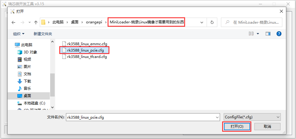
- Then click OK
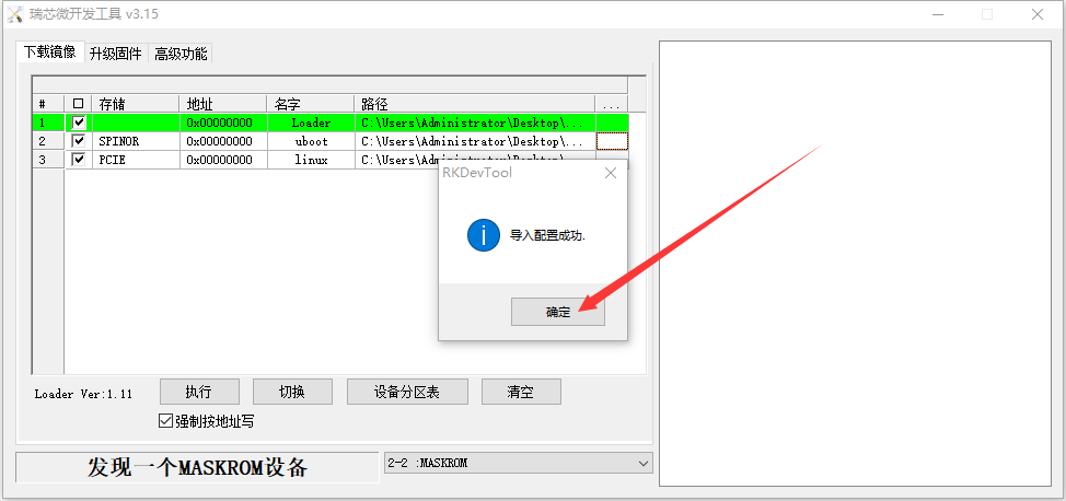
- Then click the location shown in the figure below
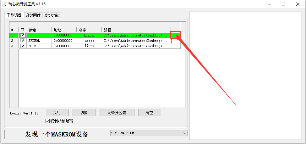
- Then select MiniLoaderAll.bin in the MiniLoader folder downloaded earlier, and then click to open
- Then click the position shown in the figure below
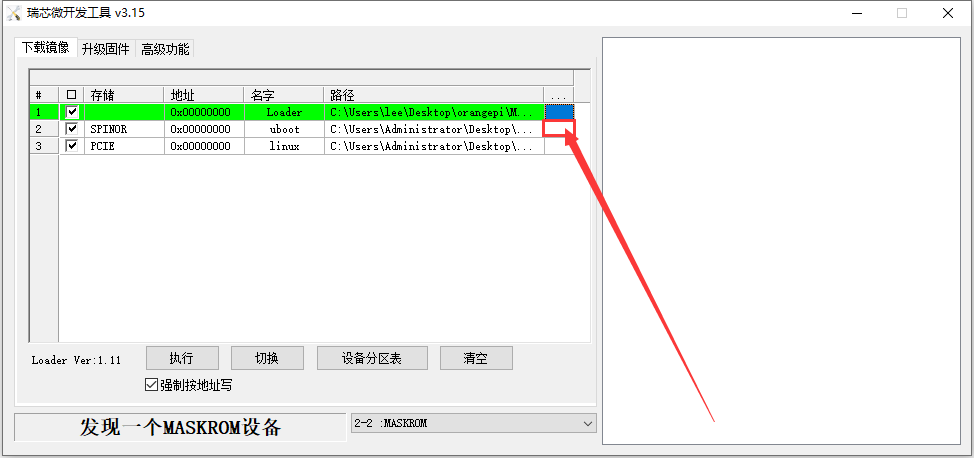
- Then enter the MiniLoader folder downloaded earlier, select rkspi_loader.img, and click Open
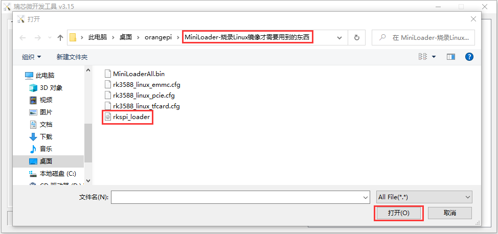
- Then click the location shown in the figure below
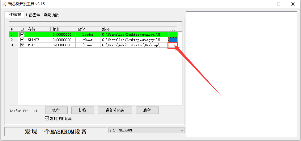
- Then select the path of the linux image you want to burn, and click Open
Before burning the image, it is recommended to rename the linux image to be burned to orangepi.img or other shorter names, so that you can see the percentage value of the burning progress when burning the image.
- Then please check the option to force write by address
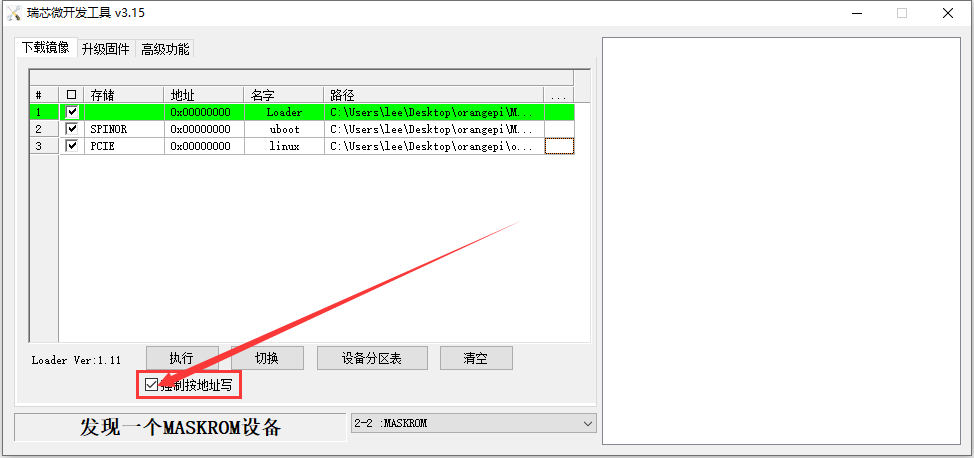
- Click the Execute button again to start burning the u-boot+linux image to SPIFlash+SSD
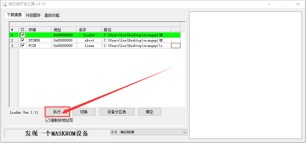
- The display log after burning the image is shown in the figure below
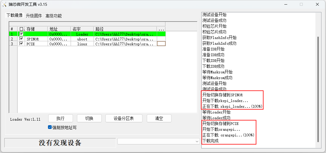
If there is a problem with burning, please clear the SPIFlash first and then try burning again. For the method of clearing SPIFlash, please refer to the instructions in the section of using RKDevTool to clear SPIFlash.
- After the image is burnt, it will automatically start the linux system in SPIFlash+PCIe SSD. If it does not start normally, please power on and try again.


How to burn OpenWRT image to SPI FLASH
|
The method introduced in this section is to burn the entire OpenWRT image to spi flash, no nvme ssd is required. In other words, u-boot, kernel and rootfs are all stored in spi flash. Since the spi flash on the development board is only 16MB, this system basically cannot install much software, and currently only some basic functions can be realized. |
The method of using the dd command to burn
- Burning the OpenWRT image to SPIFlash needs to be completed with the help of a TF card, so first you need to burn the OpenWRT image that supports TF card startup to the TF card, and then use the TF card to start the development board to enter the OpenWRT system. For the method of burning the OpenWRT image to the TF card, please refer to the instructions in the two sections of the method of burning the Linux image to the TF card based on the Windows PC and the method of burning the Linux image to the TF card based on the Ubuntu PC.
- Then download the OpenWRT image that can boot from SPIFlash from Orange Pi's download page. After opening the download link, you can see the following two types of OpenWRT images, please select the image in the SPIFlash boot image folder to download
Then upload the image downloaded from the official website to the TF card.
Then execute the following command to burn the OpenWRT image into SPIFlash. Note that after if=, you need to specify the actual path where the image is stored
|
root@OpenWrt:~# dd if=openwrt-rockchip-armv8-xunlong_orangepi-5-plus-spi-squashfs-sysupgrade.bin of=/dev/mtdblock0 |
- Then you can use the poweroff command to shut down. Then please pull out the TF card, and then short press the power button to turn on, and then the OpenWRT system in SPIFlash will be started.
Using RKDevTool to burn
- The position of the SPI Flash on the development board is shown in the figure below, no other settings are required before starting the programming
- Then you need to prepare a data cable with good quality Type-C interface
Then download the Rockchip driver DriverAssitant_v5.12.zip and MiniLoader and the burning tool RKDevTool_Release_v3.15.zip from the Orange Pi's download page
- On the download page of Orange Pi, first select the official tool, and then enter the following folder

- Then download all the files below
Note that the "MiniLoader-things needed to burn the Linux image" folder is hereinafter referred to as the MiniLoader folder.
- Then download the OpenWRT image that can be booted from SPIFlash from the download page of Orange Pi. Limited by the capacity of SPIFlash, the image size is less than 16MB. After opening the download link, you can see the following two types of OpenWRT images, please select the image in the SPIFlash boot image folder

- Then use decompression software to decompress DriverAssitant_v5.12.zip, and then find the DriverInstall.exe executable file in the decompressed folder and open it
After opening DriverInstall.exe, the steps to install the Rockchip driver are as follows
- Click the "Driver Installation" button
- After waiting for a period of time, a pop-up window will prompt "driver installed successfully", and then click the "OK" button.
- Then decompress RKDevTool_Release_v3.15.zip, this software does not need to be installed, just find RKDevTool in the decompressed folder and open it
- After opening the RKDevTool burning tool, because the computer has not been connected to the development board through the Type-C cable at this time, the lower left corner will prompt "No device found"
Then start burning the OpenWRT image into SPI FLASH
- First, connect the development board to the Windows computer through the Type-C data cable. The position of the Type-C interface on the development board is shown in the figure below
Make sure the development board is not connected to the power supply, and the TF card and eMMC module are not inserted
Then press and hold the MaskROM button on the development board. The position of the MaskROM button on the development board is shown in the figure below:
- Then connect the power supply of the Type-C interface to the development board, and power on, and then release the MaskROM button
- If the previous steps are successful, the development board will enter the MASKROM mode at this time, and the interface of the burning tool will prompt "Found a MASKROM device"
- Then place the mouse cursor in the area below
- Then click the right mouse button and the selection interface shown in the figure below will pop up
- Then select the Import configuration option
- Then select the rk3588_linux_spiflash.cfg configuration file in the MiniLoader folder downloaded earlier, and click Open
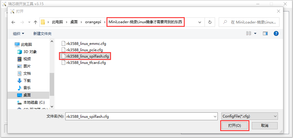
- Then click OK
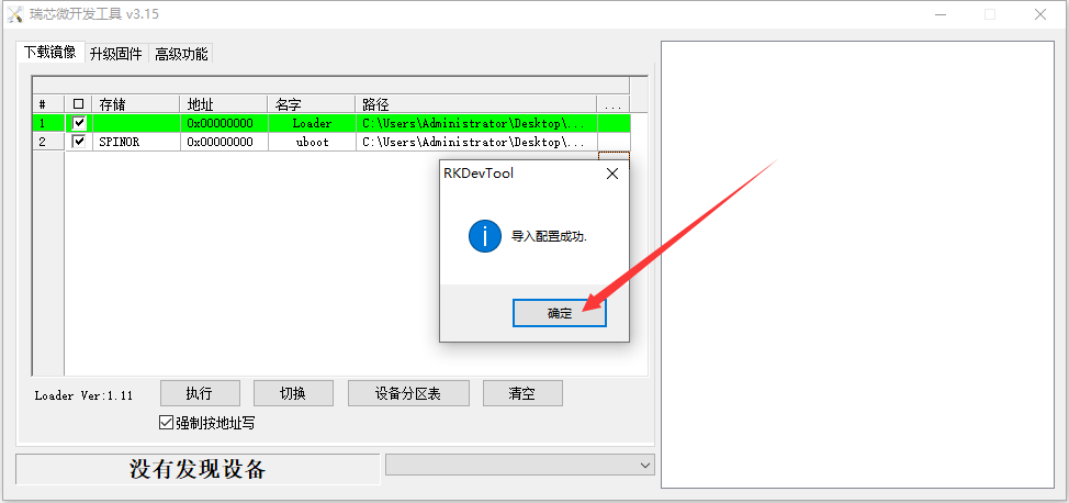
- Then click the location shown in the figure below
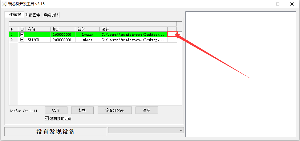
- Then select MiniLoaderAll.bin in the MiniLoader folder downloaded earlier, and click Open
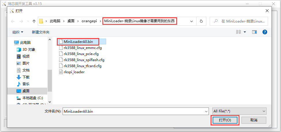
- Then click the location shown in the figure below
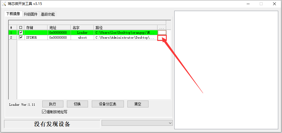
Then select the path of the OpenWRT image you want to burn, and click Open
Before burning the image, it is recommended to rename the OpenWRT image to be burned to orangepi.img or other shorter names, so that you can see the percentage value of the burning progress when burning the image.
- Then please make sure that the option to force writing by address is ticked

- Click the Execute button again to start burning the OpenWRT image into SPIFlash
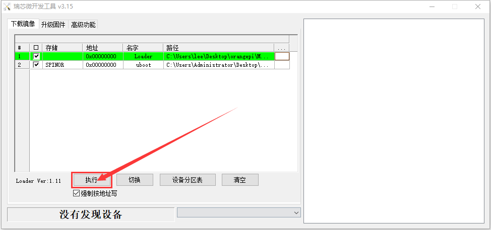
- The display log after burning the OpenWRT image is shown in the figure below
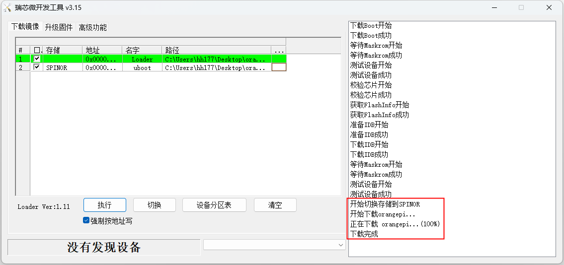
If there is a problem with burning, please clear the SPIFlash first and then try burning again. For the method of clearing SPIFlash, please refer to the instructions in the section of using RKDevTool to clear SPIFlash.
- The OpenWRT image will start automatically after burning, if it does not start normally, please try again with power on.


How to burn Android image to TF card
First prepare a TF card with a capacity of 16GB or greater. The transmission speed of the TF card must be class10 or above. It is recommended to use a TF card of SanDisk and other brands
Then use the card reader to insert the TF card into the computer
Then download the SDDiskTool programming tool from the Orange Pi's download page, please make sure that the version of the SDDiskTool tool is the latest v1.72
Then download the Android12 image from the Orange Pi download page
- After opening the download link of the Android image, you can see the following two types of Android images, please select the image in the TF card and eMMC boot image folder to download
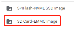
- After entering the TF card and eMMC boot image folder, you can see the following three images, the difference between them is:
a) The first image is dedicated to HDMI display and supports 8K display. If you don’t use LCD screen, please download the image without lcd
b) If you want to use lcd screen, please choose image with lcd
c) The image with box is a image dedicated to the TV box
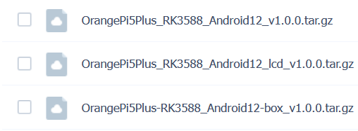

Then use decompression software to decompress the compressed package of the downloaded Android image. Among the decompressed files, the file ending with ".img" is the Android image file, and the size is more than 1GB
Then use decompression software to decompress SDDiskTool_v1.72.zip, this software does not need to be installed, just find SD_Firmware_Tool.exe in the decompressed folder and open it

- After opening SDDiskTool, if the TF card is recognized normally, the inserted disk device will be displayed in the "Select Removable Disk Device" column. Please make sure that the displayed disk device is consistent with the drive letter of the TF card you want to burn If there is no display, you can try to unplug the TF card

- After confirming the drive letter, you can format the TF card first, click the restore disk button in SDDiskTool, or use the SD Card Formatter mentioned above to format the TF card

- Then start to write the Android image to the TF card
a. First check "SD Boot" in "Select Function Mode"
b. Then select the path of the Android image in the "Select to upgrade firmware" column
c. Finally click the "Start Create" button to start burning the Android image to the TF card

- After burning, you can exit the SDDiskTool software, and then you can pull out the TF card from the computer and insert it into the development board to start

How to burn Android image into eMMC
|
Note, after burning the image into eMMC, if the test finds that it cannot be started, please clear the SPIFlash and try again. For the method of clearing SPIFlash, please refer to the method of using RKDevTool to clear SPIFlash. |
How to burn Android image into eMMC via Type-C cable
|
Note that all the following operations are performed on a Windows computer. |
- The development board reserves an eMMC expansion interface. Before programming the system to eMMC, you first need to purchase an eMMC module that matches the eMMC interface of the development board. Then install the eMMC module to the development board. The location of the eMMC interface is as follows:
It is also necessary to prepare a data cable with a good quality Type-C interface
Then download Rockchip driver DriverAssitant_v5.12.zip and burning tool RKDevTool_Release_v3.15.zip from Orange Pi's download page
Then download the Android image from Orange Pi's download page.
- After opening the download link of the Android image, you can see the following two types of Android images, please select the image in the TF card and eMMC startup image folder to download
- After entering the TF card and eMMC boot image folder, you can see the following three images, the difference between them is:
The first image is dedicated to HDMI display and supports 8K display. If you don’t use LCD screen, please download the image without lcd
If you want to use lcd screen, please choose image with lcd
The image with box is a image dedicated to the TV box


Then use the decompression software to decompress the compressed package of the downloaded Android image. Among the decompressed files, the file ending with ".img" is the Android image file, and the size is more than 1GB
Then use decompression software to decompress DriverAssitant_v5.12.zip, and then find the DriverInstall.exe executable file in the decompressed folder and open it
After opening DriverInstall.exe, the steps to install the Rockchip driver are as follows
- Click the "Driver Installation" button
- After waiting for a period of time, a pop-up window will prompt "driver installed successfully", then click "OK"
- Then decompress RKDevTool_Release_v3.15.zip, this software does not need to be installed, just find RKDevTool in the decompressed folder and open it
- After opening the RKDevTool burning tool, because the computer has not been connected to the development board through the Type-C cable at this time, the lower left corner will prompt "No device found"
Then start burning the Android image into eMMC
- First, connect the development board to the Windows computer through the Type-C data cable. The position of the Type-C interface on the development board is shown in the figure below
Then make sure that the development board is not inserted into the TF card and not connected to the power supply
Then press and hold the MaskROM button on the development board, the position of the MaskROM button on the development board is shown in the figure below:
- Then connect the power supply of the Type-C interface to the development board, and power on
- If the previous steps are successful, the development board will enter the MASKROM mode at this time, and the interface of the burning tool will prompt "found a MASKROM device"
- Then click the "Upgrade Firmware" column of the burning tool
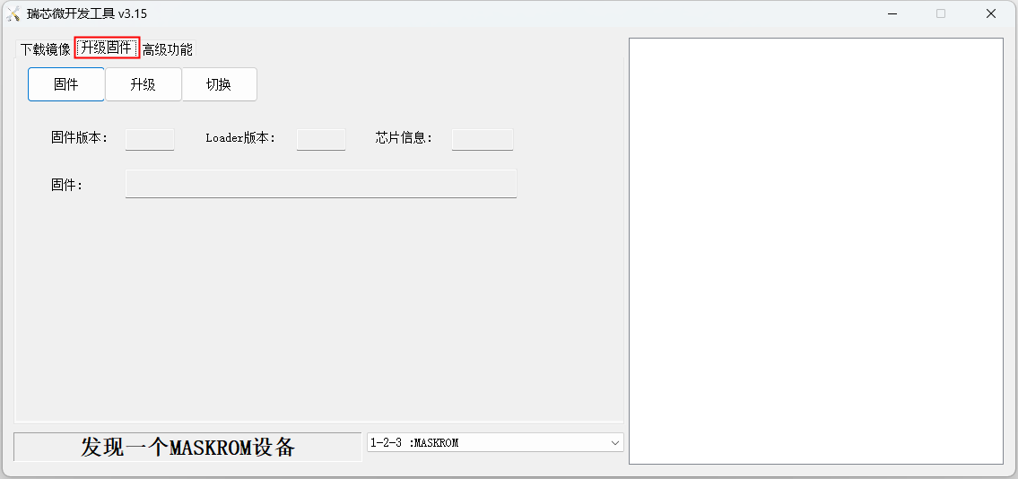
- Then click the "Firmware" button to select the path of the Android image that needs to be burned
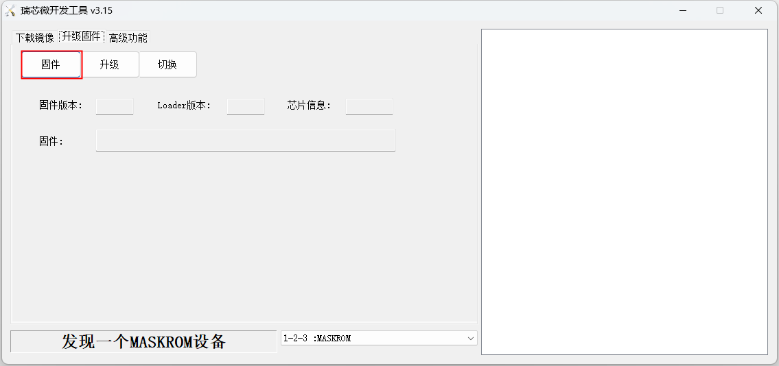
Finally, click the "Upgrade" button to start burning, and the log during the burning process is shown in the figure below. After burning is completed, the Android system will start automatically.
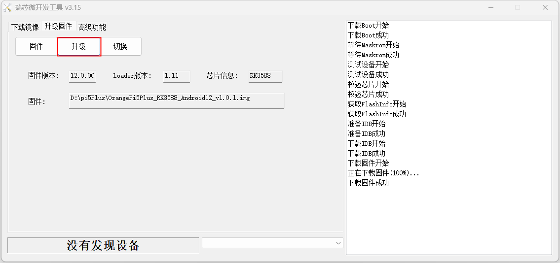


How to burn Android 12 image into eMMC via TF card
|
Note that all the following operations are performed on a Windows computer. |
- The development board reserves an eMMC expansion interface. Before programming the system to eMMC, you first need to purchase an eMMC module that matches the eMMC interface of the development board. Then install the eMMC module to the development board. The location of the eMMC interface is as follows:
You also need to prepare a TF card with 8GB or larger capacity. The transmission speed of the TF card must be class10 or above. It is recommended to use a TF card of SanDisk and other brands
Then use the card reader to insert the TF card into the computer
Then download the SDDiskTool programming tool from the Orange Pi's download page, please ensure that the version of the SDDiskTool tool is the latest v1.72
Then download the Android image from the Orange Pi's download page
- After opening the download link of the Android image, you can see the following two types of Android images, please select the image in the TF card and eMMC startup image folder to download

After entering the TF card and eMMC boot image folder, you can see the following three images, the difference between them is:
The first image is dedicated to HDMI display and supports 8K display. If you don’t use LCD screen, please download the image without lcd
If you want to use lcd screen, please choose mirror with lcd
The mirror with box is a mirror dedicated to the TV box
Then use decompression software to decompress the compressed package of the downloaded Android image. Among the decompressed files, the file ending with ".img" is the Android image file, and the size is more than 1GB
Then use decompression software to decompress SDDiskTool_v1.72.zip, this software does not need to be installed, just find SD_Firmware_Tool.ex in the decompressed folder and open it
- After opening SDDiskTool, if the TF card is recognized normally, the inserted disk device will be displayed in the "Select Removable Disk Device" column. Please make sure that the displayed disk device is consistent with the drive letter of the TF card you want to burn, if there is no display, you can try to unplug the TF card
- After confirming the drive letter, you can format the TF card first, click the restore disk button in SDDiskTool, or use the SD Card Formatter mentioned above to format the TF card
Then start to write the Android image into the TF card
First confirm that the displayed drive letter is the drive letter corresponding to the TF card under "Select Removable Disk Device"
Then select "Firmware Upgrade" in "Select Function Mode"
Then select the path of the Android firmware in the "Select Upgrade Firmware" column
Finally click the "Start Create" button to start burning
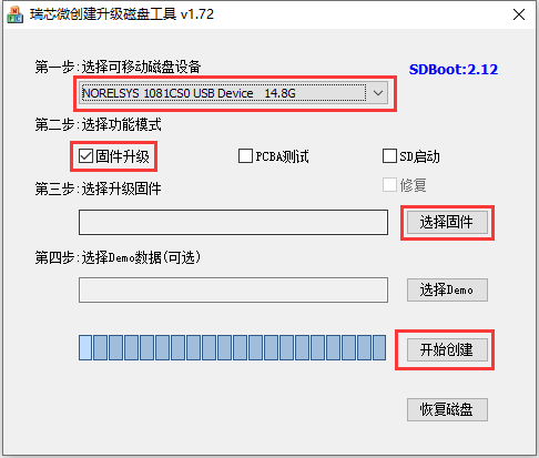
After the burning is completed, the display is as shown in the figure below, and then you can exit SDDiskTool

Then pull out the TF card from the computer and insert it into the development board. After the development board is powered on, it will automatically start burning the Android image in the TF card to the eMMC of the development board.
If the development board is connected to an HDMI display, you can also see the progress bar of burning the Android image to eMMC from the HDMI display

When the HDMI monitor displays the following information, it means that the burning of the Android image into the eMMC has been completed. At this time, the TF card can be pulled out, and then the Android system in the eMMC will start.
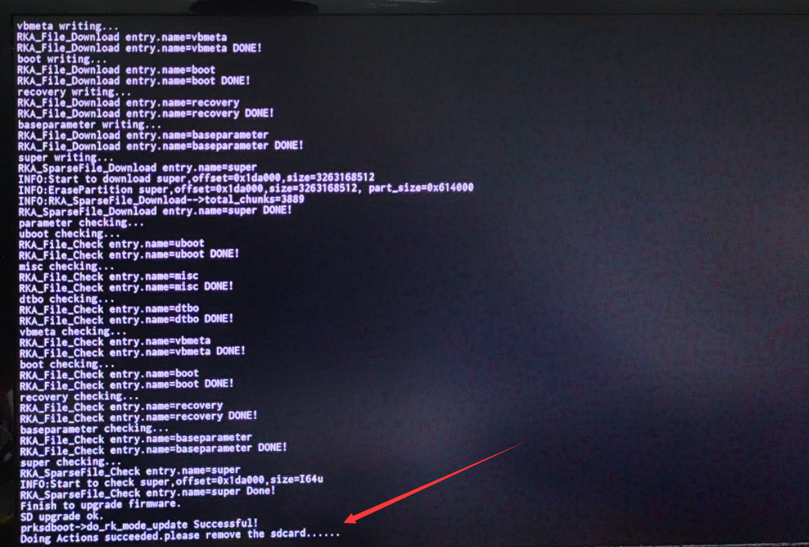
How to burn Android image to SPIFlash+NVMe SSD
|
Note that all the following operations are performed on a Windows computer. |
- First, you need to prepare an M-Key 2280 specification NVMe SSD solid state drive, and the specification of the PCIe interface in the M.2 slot of the development board is PCIe3.0x4.
- Then insert the NVMe SSD into the M.2 PCIe interface of the development board and fix it
- The position of the SPI Flash on the development board is shown in the figure below, no other settings are required before starting the programming
- It is also necessary to prepare a data cable with a good quality Type-C interface
Then download Rockchip driver DriverAssitant_v5.12.zip and burning tool RKDevTool_Release_v3.15.zip from Orange Pi's download page
Then download the Android12 image from the Orange Pi's download page
- After opening the download link of the Android image, you can see the following two types of Android images, please select the image in the SPIFlash-NVME SSD boot image folder to download
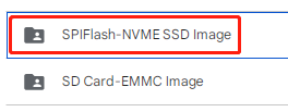
After entering the SPIFlash-NVME SSD boot image folder, you can see the following three images. Their differences are:
The first image is dedicated to HDMI display and supports 8K display. If you don’t use LCD screen, please download the image without lcd
If you want to use lcd screen, please choose image with lcd
The image with box is a image dedicated to the TV box
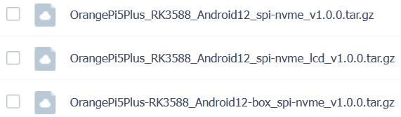


- Then use the decompression software to decompress DriverAssitant_v5.12.zip, and then find the DriverInstall.exe executable file in the decompressed folder and open it
- 8. After opening DriverInstall.exe, the steps to install the Rockchip driver are as followsa. Click the "Driver Install" button
- a. After waiting for a period of time, a pop-up window will prompt "driver installed successfully", then click the "OK" button
- 9. Then decompress RKDevTool_Release_v3.15.zip, this software does not need to be installed, just find RKDevTool in the decompressed folder and open it
- After opening the RKDevTool burning tool, because the computer is not connected to the development board through the Type-C cable at this time, the lower left corner will prompt "No device found"
Then start burning the Android image to SPIFlash+NVMe SSD
- First, connect the development board to the Windows computer through the Type-C data cable. The position of the Type-C interface on the development board is shown in the figure below
Make sure that the development board is not plugged into TF and eMMC modules, and is not connected to the power supply
Then press and hold the MaskROM button on the development board, the position of the MaskROM button on the development board is shown in the figure below:
- Then connect the power supply of the Type-C interface to the development board, and power on, and then release the MaskROM button
- If the previous steps are successful, the development board will enter the MASKROM mode at this time, and the interface of the burning tool will prompt "Found a MASKROM device"
- Then click the "Upgrade Firmware" column of the burning tool
- Then click the "Firmware" button to select the Android image to be burned
- Finally, click the "Upgrade" button to start burning. The burning process is shown in the figure below. After the burning is completed, the Android system will automatically start.
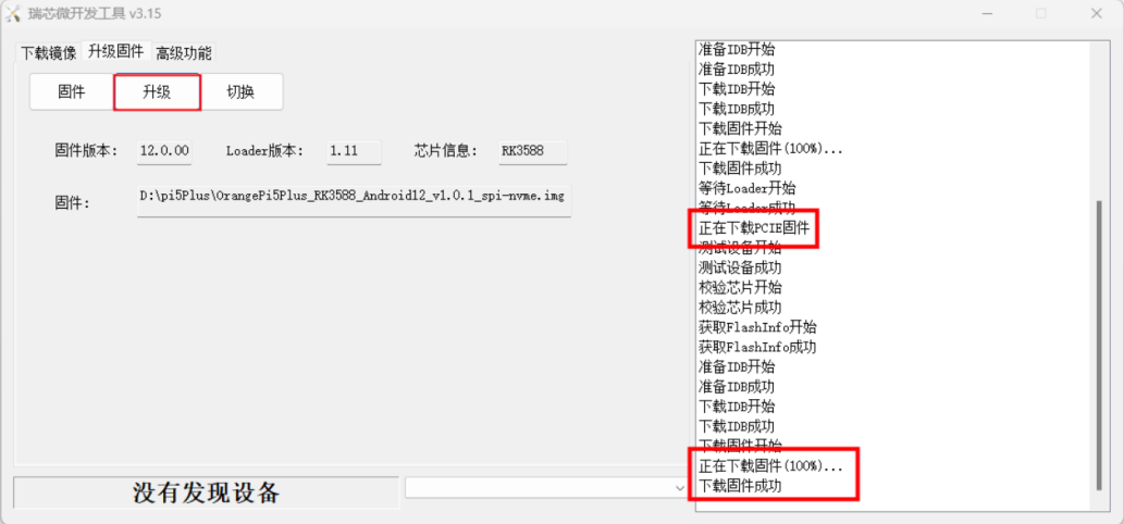

How to burn Orange Pi OS (Droid) image to TF card
|
Note that all the following operations are performed on a Windows computer. |
- First prepare a TF card with 8GB or larger capacity. The transmission speed of the TF card must be class10 or above. It is recommended to use a TF card of SanDisk and other brands
- Then use the card reader to insert the TF card into the computer
- Then download the SDDiskTool programming tool from the Orange Pi's download page, please make sure that the version of the SDDiskTool tool is the latest v1.72.
- Then download the Orange Pi OS (Droid) image from the Orange Pi's download page, open the download link of the Orange Pi OS (Droid) image, and you can see the following two types of images, please select the image below
Then use decompression software to decompress the compressed file of the downloaded Orange Pi OS (Droid) image. Among the decompressed files, the file ending with ".img" is the Orange Pi OS (Droid) image file, and the size is more than 1GB
Then use decompression software to decompress SDDiskTool_v1.72.zip, this software does not need to be installed, just find SD_Firmware_Tool.ex in the decompressed folder and open it
- After opening SDDiskTool, if the TF card is recognized normally, the inserted disk device will be displayed in the "Select Removable Disk Device" column. Please make sure that the displayed disk device is consistent with the drive letter of the TF card you want to burn , if there is no display, you can try to unplug the TF card
- After confirming the drive letter, you can format the TF card first, click the restore disk button in SDDiskTool, or use the SD Card Formatter mentioned above to format the TF card
Then start to write the Orange Pi OS (Droid) image into the TF card
First check "SD Boot" in "Select Function Mode"
Then select the path of the Orange Pi OS (Droid) image in the "Select to upgrade firmware" column
Finally, click the "Start Create" button to start burning the Orange Pi OS (Droid) image to the TF card
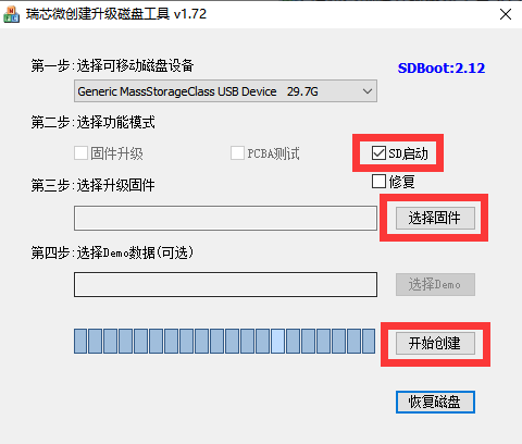
- After burning, you can exit the SDDiskTool software, and then you can pull out the TF card from the computer and insert it into the development board to start
How to burn Orange Pi OS (Droid) image into eMMC
|
Note, after burning the image into eMMC, if the test finds that it cannot be started, please clear the SPIFlash and try again. For the method of clearing SPIFlash, please refer to the method of using RKDevTool to clear SPIFlash. |
Burn Orange Pi OS (Droid) image to eMMC
|
Note that all the following operations are performed on a Windows computer. |
- The development board reserves an eMMC expansion interface. Before programming the system to eMMC, you first need to purchase an eMMC module that matches the eMMC interface of the development board. Then install the eMMC module to the development board. The location of the eMMC interface is as follows:
- It is also necessary to prepare a data cable with a good quality Type-C interface
Then download Rockchip driver DriverAssitant_v5.12.zip and burning tool RKDevTool_Release_v3.15.zip from Orange Pi's download page
Then download the Orange Pi OS (Droid) image from the Orange Pi's download page

Then use decompression software to decompress the compressed file of the downloaded Orange Pi OS (Droid) image. Among the decompressed files, the file ending with ".img" is the Orange Pi OS (Droid) image file, and the size is more than 1GB
Then use decompression software to decompress DriverAssitant_v5.12.zip, then find the DriverInstall.exe executable file in the decompressed folder and open it
After opening DriverInstall.exe, the steps to install the Rockchip driver are as follows
- Click the "Driver Installation" button
- After waiting for a period of time, a pop-up window will prompt "driver installed successfully", and then click the "OK" button.
- Then decompress RKDevTool_Release_v3.15.zip, this software does not need to be installed, just find RKDevTool in the decompressed folder and open it
- After opening the RKDevTool burning tool, because the computer is not connected to the development board through the Type-C cable at this time, the lower left corner will prompt "No device found"
Then start burning Orange Pi OS (Droid) image into eMMC
- First, connect the development board to the Windows computer through the Type-C data cable. The position of the Type-C interface on the development board is shown in the figure below
Make sure that the development board is not inserted into the TF card and not connected to the power supply
Then press and hold the MaskROM button on the development board, the position of the MaskROM button on the development board is shown in the figure below:
- Then connect the power supply of the Type-C interface to the development board, and power on
- If the previous steps are successful, the development board will enter the MASKROM mode at this time, and the interface of the burning tool will prompt "found a MASKROM device"
- Then click the "Upgrade Firmware" column of the burning tool
- Then click the "Firmware" button to select the path of the Orange Pi OS (Droid) image that needs to be burned
- Finally, click the "Upgrade" button to start burning, and the log during the burning process is shown in the figure below. After burning, the Orange Pi OS (Droid) system will start automatically.
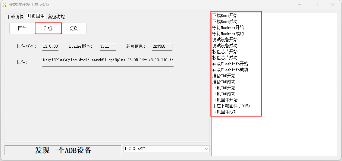

Burn Orange Pi OS (Droid) image to eMMC via TF card
|
Note that all the following operations are performed on a Windows computer. |
- The development board reserves an eMMC expansion interface. Before programming the system to eMMC, you first need to purchase an eMMC module that matches the eMMC interface of the development board. Then install the eMMC module to the development board. The location of the eMMC interface is as follows:

You also need to prepare a TF card with 8GB or larger capacity. The transmission speed of the TF card must be class10 or above. It is recommended to use a TF card of SanDisk and other brands
Then use the card reader to insert the TF card into the computer
Then download the SDDiskTool programming tool from the Orange Pi's download page, please ensure that the version of the SDDiskTool tool is the latest v1.72.
Then download the Orange Pi OS (Droid) image from the Orange Pi's download page
Then use the decompression software to decompress the compressed package of the downloaded Orange Pi OS (Droid) image. Among the decompressed files, the file ending with ".img" is the Orange Pi OS (Droid) image file, and the size is more than 1GB
Then use decompression software to decompress SDDiskTool_v1.72.zip, this software does not need to be installed, just find SD_Firmware_Tool.exe in the decompressed folder and open it
- After opening SDDiskTool, if the TF card is recognized normally, the inserted disk device will be displayed in the "Select Removable Disk Device" column. Please make sure that the displayed disk device is consistent with the drive letter of the TF card you want to burn, if there is no display, you can try to unplug the TF card.
- After confirming the drive letter, you can format the TF card first, click the restore disk button in SDDiskTool, or use the SD Card Formatter mentioned above to format the TF card
- Then start to write the Orange Pi OS (Droid) image into the TF card
a. First confirm that the displayed drive letter is the drive letter corresponding to the TF card under "Select Removable Disk Device"
b. Then select "Firmware Upgrade" in "Select Function Mode"
c. Then select the path of the Orange Pi OS (Droid) firmware in the "Select Upgrade Firmware" column
d. Finally click the "Start Create" button to start burning

- After the burning is completed, the display is as shown in the figure below, and then you can exit SDDiskTool
Then pull out the TF card from the computer and insert it into the development board. After the development board is powered on, it will automatically start burning the Orange Pi OS (Droid) image in the TF card to the eMMC of the development board.
If the development board is connected to an HDMI display, you can also see the progress bar of burning the Orange Pi OS (Droid) image to eMMC from the HDMI display
- When the HDMI monitor displays the following information, it means that the burning of the Orange Pi OS (Droid) image to the eMMC has been completed. At this time, the TF card can be pulled out, and then the Orange Pi OS (Droid) system in the eMMC will start to start .

Burn Orange Pi OS (Droid) image to SPIFlash+NVMe SSD
|
Note that all the following operations are performed on a Windows computer. |
- First, you need to prepare a 2280 specification NVMe SSD solid state drive. The specification of the PCIe interface in the M.2 slot of the development board is PCIe3.0x4.
- Then insert the NVMe SSD into the M.2 PCIe interface of the development board and fix it
- The position of the SPI Flash on the development board is shown in the figure below, no other settings are required before starting the programming
- It is also necessary to prepare a data cable with a good quality Type-C interface
Then download the Rockchip driver DriverAssitant_v5.12.zip and the burning tool RKDevTool_Release_v3.15.zip from the Orange Pi's download page,
Then download the Orange Pi OS (Droid) image, open the download link of the Orange Pi OS (Droid) image and you can see the following two types of images, please select the image with spi-nvme to download

- Then use the decompression software to decompress DriverAssitant_v5.12.zip, and then find the DriverInstall.exe executable file in the decompressed folder and open it
After opening DriverInstall.exe, the steps to install the Rockchip driver are as follows
- Click the "Driver Installation" button
- After waiting for a period of time, a pop-up window will prompt "driver installed successfully", and then click the "OK" button.
- Then decompress RKDevTool_Release_v3.15.zip, this software does not need to be installed, just find RKDevTool in the decompressed folder and open it
- After opening the RKDevTool burning tool, because the computer is not connected to the development board through the Type-C cable at this time, the lower left corner will prompt "No device found"
Then start burning the Android image to SPIFlash+NVMe SSD
- First, connect the development board to the Windows computer through the Type-C data cable. The position of the Type-C interface on the development board is shown in the figure below
Make sure that the development board is not plugged into the TF and eMMC modules, and is not connected to the power supply
Then press and hold the MaskROM button on the development board, the position of the MaskROM button on the development board is shown in the figure below:
- Then connect the power supply of the Type-C interface to the development board, and power on, and then release the MaskROM button
- If the previous steps are successful, the development board will enter the MASKROM mode at this time, and the interface of the burning tool will prompt "found a MASKROM device"
- Then click the "Upgrade Firmware" column of the burning tool
- Then click the "Firmware" button to select the Orange Pi OS (Droid) image to be burned
Finally, click the "Upgrade" button to start burning. The burning process is shown in the figure below. After the burning is completed, the Orange Pi OS (Droid) system will automatically start.
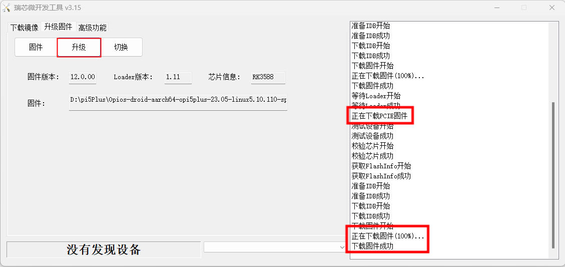

How to use RKDevTool to clear SPIFlash
The position of SPI Flash on the development board is shown in the figure below
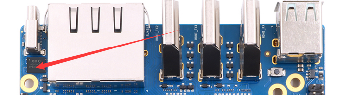
First, you need to prepare a data cable with a good quality Type-C interface
Then download the Rockchip driver DriverAssitant_v5.12.zip and MiniLoader and the burning tool RKDevTool_Release_v3.15.zip from the Orange Pi's download page
On the Orange Pi's download page, first select the official tool, and then enter the following folder
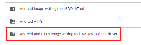
Then download all the files below
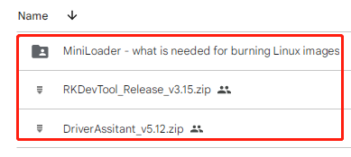
Note that the "MiniLoader-things needed to burn the Linux image" folder is hereinafter referred to as the MiniLoader folder.
Then use the decompression software to decompress DriverAssitant_v5.12.zip, and then find the DriverInstall.exe executable file in the decompressed folder and open it
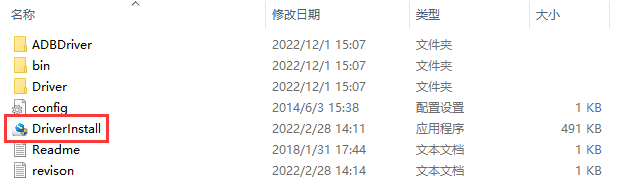
After opening DriverInstall.exe, the steps to install the Rockchip driver are as follows
Click the "Driver Installation" button
After waiting for a period of time, a pop-up window will prompt "The driver is installed successfully", and then click the "OK" button.
Then decompress RKDevTool_Release_v3.15.zip, this software does not need to be installed, just find RKDevTool in the decompressed folder and open it
After opening the RKDevTool burning tool, because the computer has not been connected to the development board through the Type-C cable at this time, the lower left corner will prompt "No device found"
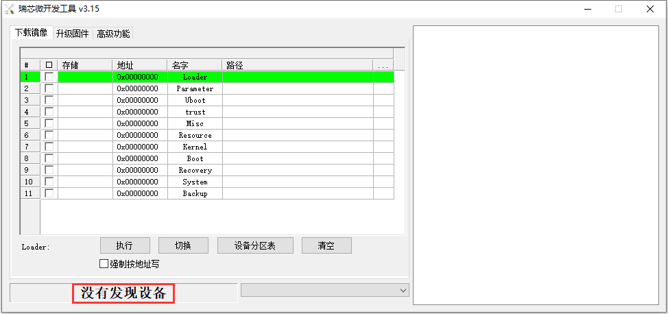
Then you can start to clear the contents of the SPI FLASH
First, connect the development board to the Windows computer through the Type-C data cable. The position of the Type-C interface on the development board is shown in the figure below
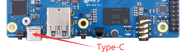
Make sure the development board is not connected to the power supply
Then press and hold the MaskROM button on the development board, the position of the MaskROM button on the development board is shown in the figure below:
Then connect the power supply of the Type-C interface to the development board, and power on, and then release the MaskROM button
If the previous steps are smooth, at this time the development board will enter the Maskrom mode, and it will be prompted "Find a Maskrom device" on the interface of the recording tool
Then please select advanced features
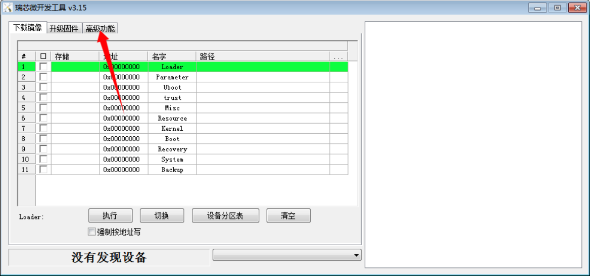
Then click the position shown in the figure below
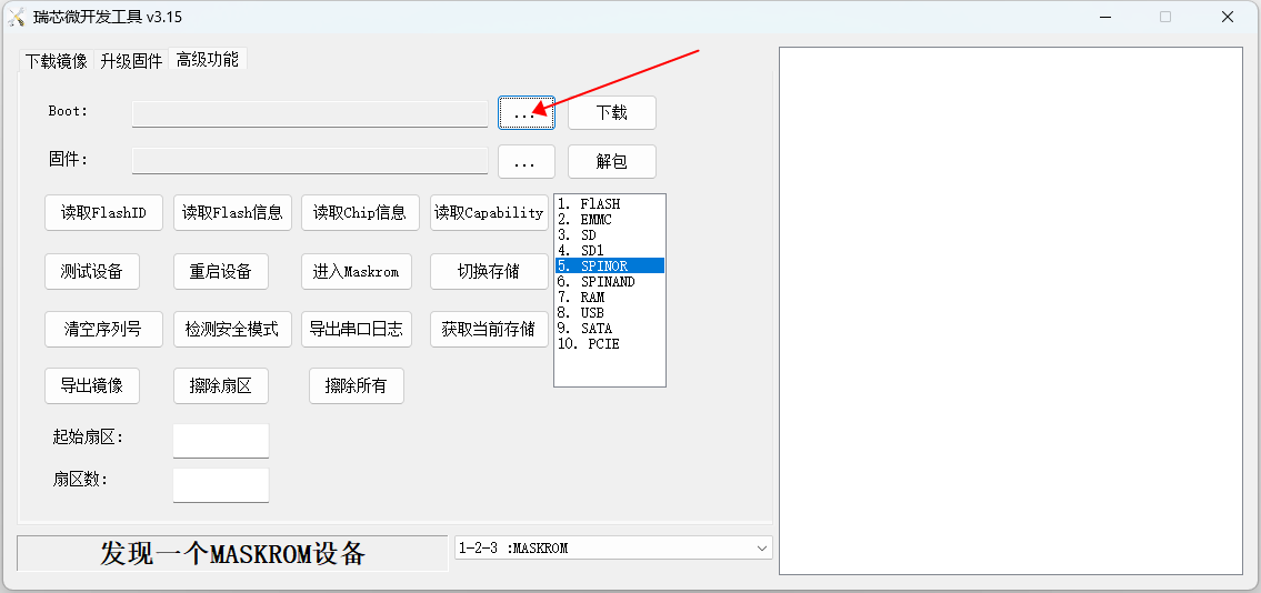
Then select MiniLoaderAll.bin in the MiniLoader folder downloaded earlier, and then click Open
Then click download
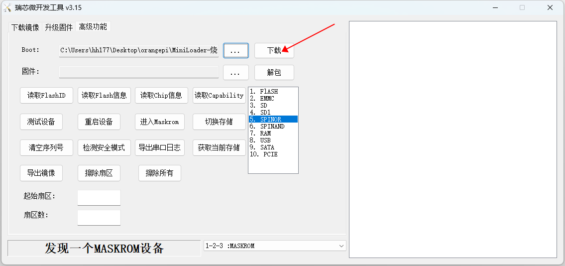
The display after downloading MiniLoaderAll.bin is shown in the figure below
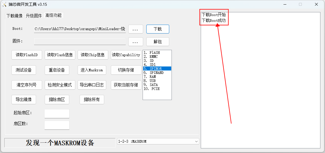
Then select the storage device as SPINOR
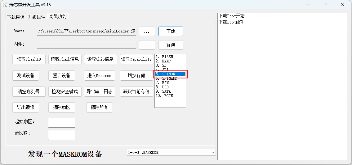
Then click switch storage
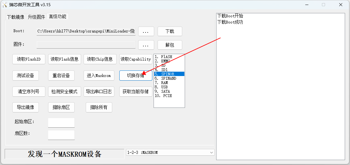
Then click Erase All to start erasing SPIFlash
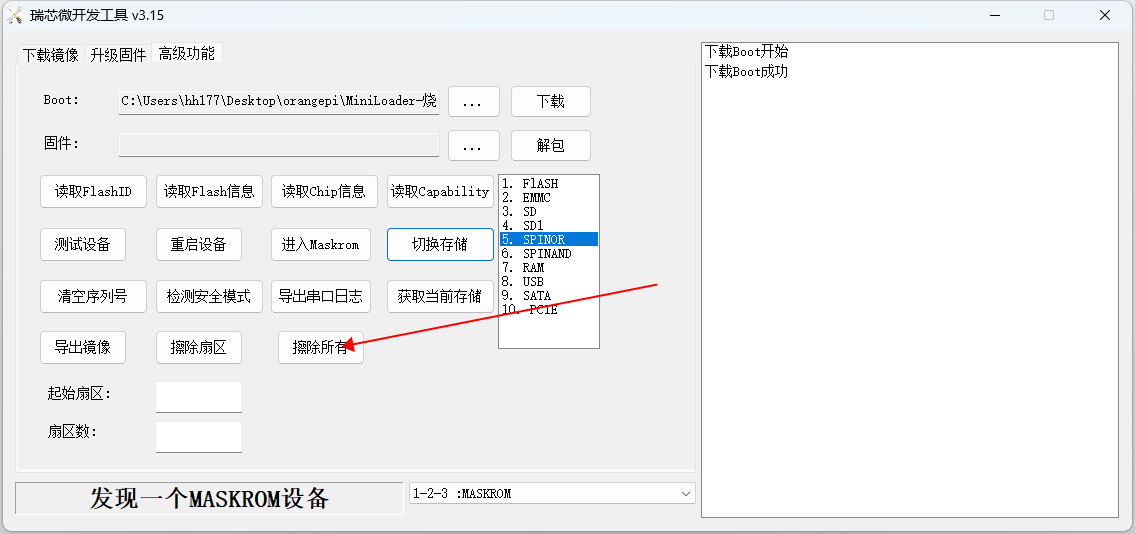
The display log after erasing SPIFlash is shown in the figure below
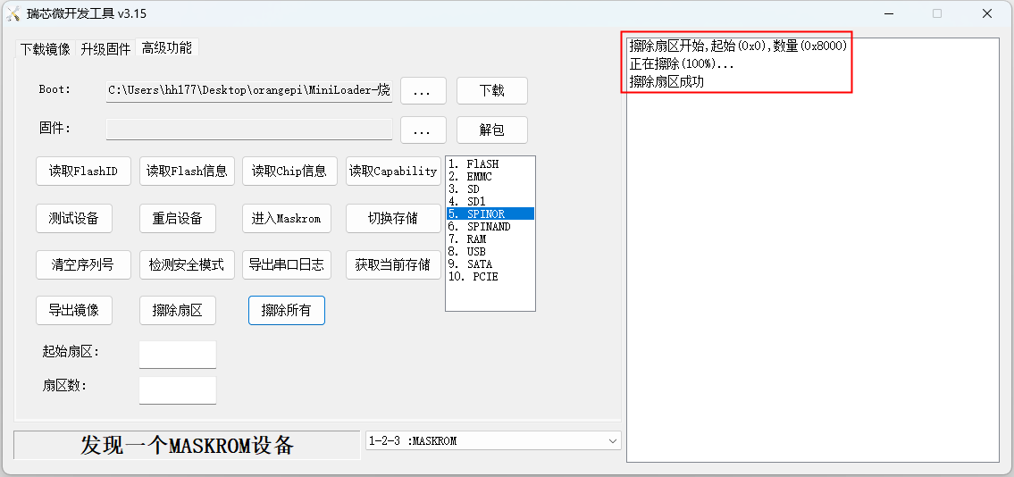


Start the Orange Pi development board
- Insert the burned TF card or eMMC module into the TF card slot of the Orange Pi development board. If the image of SPIFlash+NVMe SSD has been burnt, then there is no need to insert a TF card or eMMC module, just make sure that the NVMe SSD is normally inserted into the development board.
- The development board has an HDMI interface, and the development board can be connected to a TV or HDMI display through an HDMI-to-HDMI cable. If you buy an LCD screen, you can also use the LCD screen to display the system interface of the development board. If there is a Type-C to HDMI cable, the system interface of the development board can also be displayed through the Type-C interface.
- Connect a USB mouse and keyboard to control the Orange Pi development board.
- The development board has an Ethernet port, which can be plugged into a network cable for Internet access.
- Connect a high-quality power adapter with a 5V/4A USB Type-C interface.
Remember not to plug in a power adapter with a voltage output greater than 5V, as this will burn out the development board.
Many unstable phenomena during the power-on and start-up process of the system are basically caused by power supply problems, so a reliable power adapter is very important. If you find that there is a phenomenon of continuous restart during the startup process, please replace the power
supply or the Type-C data cable and try again.
The Type-C power port does not support PD negotiation.
In addition, please do not connect the USB interface of the computer to power the development board.
There are two Type-C ports that look the same on the development board. The one next to the network port is the power port, and the other Type-C port has no power supply function. Please don’t connect it wrong.
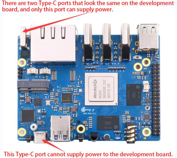

Then turn on the switch of the power adapter. If everything is normal, you can see the startup screen of the system on the HDMI monitor or LCD screen.
If you want to view the output information of the system through the debugging serial port, please use the serial cable to connect the development board to the computer. For the connection method of the serial port, please refer to the section on how to use the debugging serial port.
How to use the debugging serial port
Connection instruction of debugging serial port
- First, you need to prepare a 3.3V USB to TTL module, and then insert the USB interface end of the USB to TTL module into the USB interface of the computer.
For better compatibility, it is recommended to use CH340 USB to TTL module, please do not use CP2102, PL2303 type USB to TTL module.
Before purchasing a USB to TTL module, please confirm that the module supports a baud rate of 1500000.

The corresponding relationship between GND, RXD and TXD pins of the debugging serial port of the development board is shown in the figure below:
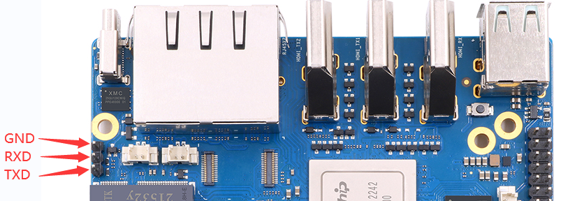
The GND, TXD and RXD pins of the USB to TTL module need to be connected to the debugging serial port of the development board through a DuPont line
The GND of the USB to TTL module is connected to the GND of the development board
The RX of the USB to TTL module is connected to the TX of the development board
The TX of the USB to TTL module is connected to the RX of the development board
The schematic diagram of connecting the USB to TTL module to the computer and the Orange Pi development board is as follows
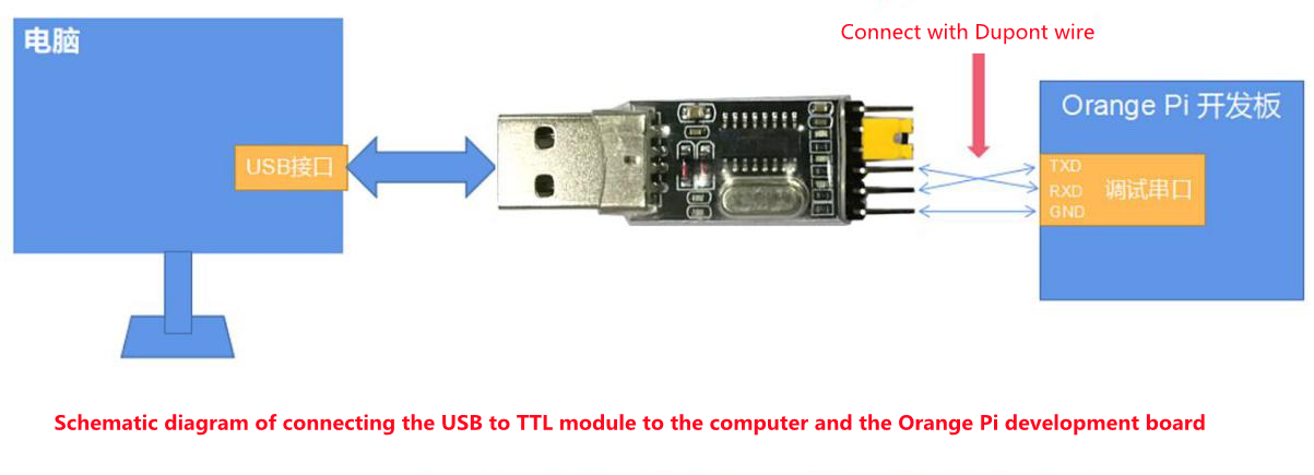
The TX and RX of the serial port need to be cross-connected. If you don’t want to carefully distinguish the order of TX and RX, you can connect the TX and RX of the serial port casually. If there is no output in the test, then exchange the order of TX and RX, so that there is always a This order is correct.


How to use the debugging serial port on the Ubuntu platform
|
There are many serial port debugging software that can be used under Linux, such as putty, minicom, etc. The following demonstrates how to use putty. |
First, insert the USB-to-TTL module into the USB port of the Ubuntu computer. If the connection and recognition of the USB-to-TTL module is normal, you can see the corresponding device node name under /dev on the Ubuntu PC. Remember this node name, and then set the serial port software will be used.
test@test:~$ ls /dev/ttyUSB*
/dev/ttyUSB0
Then use the following command to install putty on Ubuntu PC
test@test:~$ sudo apt-get update
test@test:~$ sudo apt-get install -y putty
Then run putty, remember to add sudo permission
test@test:~$ sudo putty
After executing the putty command, the following interface will pop up
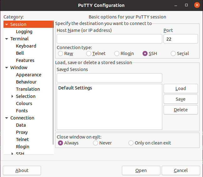
First select the setting interface of the serial port
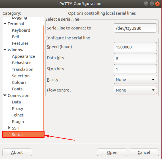
Then set the parameters of the serial port
Set the Serial line to connect to as /dev/ttyUSB0 (modify to the corresponding node name, generally /dev/ttyUSB0)
Set Speed(baud) to 1500000 (the baud rate of the serial port)
Set Flow control to None
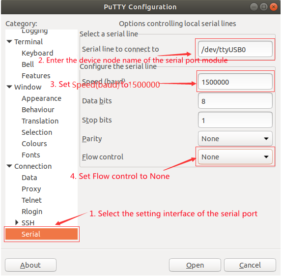
After setting the serial port setting interface, return to the Session interface
First select the Connection type as Serial
Then click the Open button to connect to the serial port
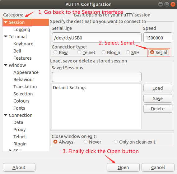
After starting the development board, you can see the Log information output by the system from the opened serial port terminal


How to use the debugging serial port on Windows platform
|
There are many serial port debugging software that can be used under Windows, such as SecureCRT, MobaXterm, etc. The following demonstrates how to use MobaXterm. This software has a free version and can be used without buying a serial number. |
Download MobaXterm
Download MobaXterm website as follows
After entering the MobaXterm download page, click GET XOBATERM NOW!
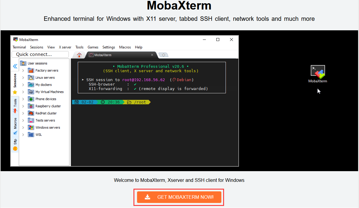
Then choose to download the Home version
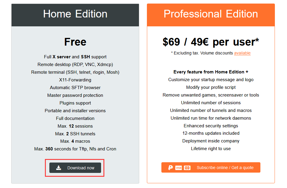
Then select Portable portable version, no need to install after downloading, just open it and use it
After downloading, use decompression software to decompress the downloaded compressed package, you can get the executable software of MobaXterm, and then double-click to open
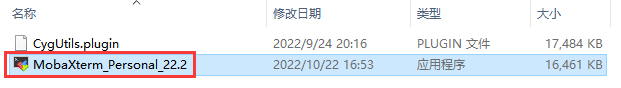
After opening the software, the steps to set up the serial port connection are as follows
Open the session settings interface
Select the serial port type
Select the port number of the serial port (select the corresponding port number according to the actual situation), if you cannot see the port number, please use 360 Driver Master to scan and install the driver for the USB to TTL serial port chip
Select the baud rate of the serial port as 1500000
Finally click the "OK" button to complete the settings


After clicking the "OK" button, you will enter the following interface. At this time, start the development board and you can see the output information of the serial port
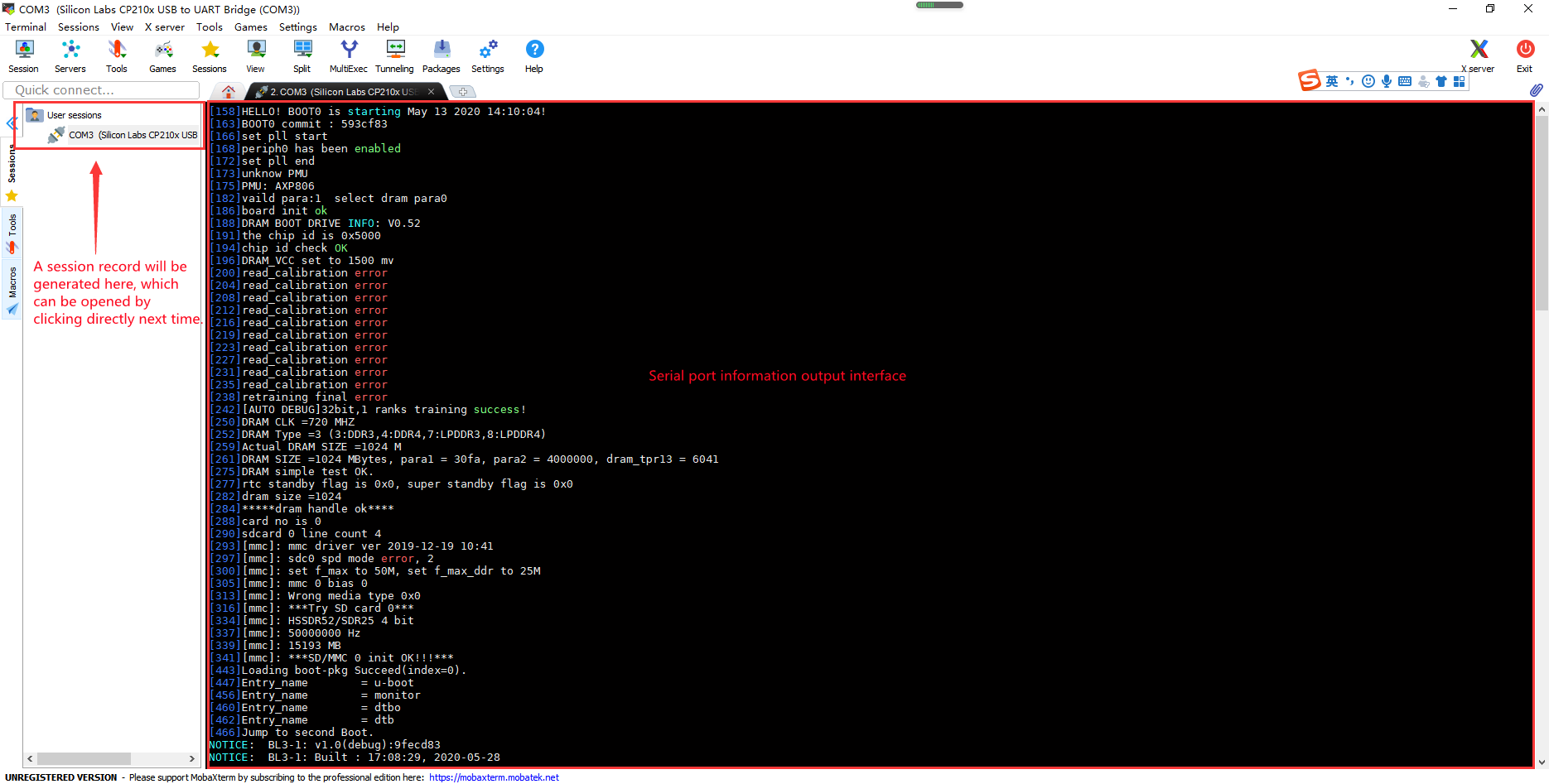

Instructions for using the 5v pin in the 40pin interface of the development board to supply power
|
The power supply method we recommend for the development board is to use the 5V/4A or 5V/5A Type-C interface power cord to plug into the Type-C power interface of the development board for power supply. If you need to use the 5V pin in the 40pin interface to power the development board, please make sure that the power cable and power adapter used can meet the power supply requirements of the development board. If the use is unstable, please switch back to the Type-C power supply. |
First, you need to prepare a power cord as shown in the figure below

The power cord shown in the picture above can be bought on Taobao, please search and buy by yourself.
Use the 5V pin in the 40pin interface to supply power to the development board. The connection method of the power line is as follows
The USB A port of the power cord shown in the above picture needs to be plugged into the 5V/4A or 5V/5A power adapter connector (please do not plug into the USB port of the computer for power supply, nor can the general mobile phone charging head, because the development board Without the PD function, the general mobile phone charging head can only output the lowest 5V/2A)
The red DuPont line needs to be plugged into the 5V pin of the development board 40pin
The black DuPont line needs to be inserted into the GND pin of the 40pin interface
The positions of the 5V pin and the GND pin of the 40pin interface in the development board are shown in the figure below, remember not to reverse the connection
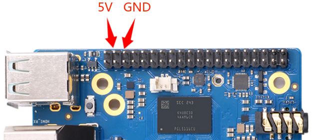


Ubuntu/Debian Server and Xfce desktop system instructions
|
The content of this chapter is written based on the Ubuntu/Debian server version image and the xfce desktop version image. If you are using the Ubuntu22.04 Gnome image, please first check the instructions in the chapter Ubuntu22.04 Gnome Wayland Desktop System Instructions. You can refer to the instructions in this chapter for the content that does not exist in the chapter of Ubuntu22.04 Gnome Wayland Desktop System User Manual, but some details may be different, please pay special attention to this point. If you are using the OPi OS Arch image, please refer to the chapter Orange Pi OS Arch System Instructions. |
Supported Ubuntu/Debian image types and kernel versions
| Linux image type | kernel version | server version | desktop version |
| Debian 11 - Bullseye | Linux5.10 | support | support |
| Debian 12 - Bookworm | Linux5.10 | plan support | plan support |
| Ubuntu 20.04 - Focal | Linux5.10 | support | support |
| Ubuntu 22.04 - Jammy | Linux5.10 | support | support |
Linux system adaptation
| Function | Linux5.10 driver | Debian11 | Ubuntu20.04 | Ubuntu22.04 |
| HDMI TX1 Video | OK | OK | OK | OK |
| HDMI TX1 Audio | OK | OK | OK | OK |
| HDMI TX2 Video | OK | OK | OK | OK |
| HDMI TX2 Audio | OK | OK | OK | OK |
| HDMI RX Video | OK | OK | OK | OK |
| HDMI RX Audio | OK | OK | OK | OK |
| USB2.0X2 | OK | OK | OK | OK |
| USB3.0X2 | OK | OK | OK | OK |
| 2.5G PCIe network port X2 | OK | OK | OK | OK |
| 2.5G PCIe network port light | OK | OK | OK | OK |
| Debug serial port | OK | OK | OK | OK |
| RTC Chip | OK | OK | OK | OK |
| FAN interface | OK | OK | OK | OK |
| eMMC Extension ports | OK | OK | OK | OK |
| AP6275P-WIFI | OK | OK | OK | OK |
| AP6275P-BT | OK | OK | OK | OK |
| AX200-WIFI | OK | OK | OK | OK |
| AX200-BT | OK | OK | OK | OK |
| AX210-WIFI | OK | OK | OK | OK |
| AX210-BT | OK | OK | OK | OK |
| RTL8852BE-WIFI | OK | OK | OK | OK |
| RTL8852BE-BT | OK | OK | OK | OK |
| MaskROM button | OK | OK | OK | OK |
| Type-C转USB3.0 | OK | OK | OK | OK |
| Type-C ADB Function | OK | OK | OK | OK |
| Type-C DP Video | OK | OK | OK | OK |
| Type-C DP Audio | OK | OK | OK | OK |
| switch button | OK | OK | OK | OK |
| infrared function | OK | OK | OK | OK |
| Three-color LED light | OK | OK | OK | OK |
| Onboard MIC | OK | OK | OK | OK |
| headphone playback | OK | OK | OK | OK |
| headphone recording | OK | OK | OK | OK |
| SPK Horn | OK | OK | OK | OK |
| 40PIN GPIO | OK | OK | OK | OK |
| 40PIN I2C | OK | OK | OK | OK |
| 40PIN SPI | OK | OK | OK | OK |
| 40PIN UART | OK | OK | OK | OK |
| 40PIN CAN | OK | OK | OK | OK |
| 40PIN PWM | OK | OK | OK | OK |
| TF card start | OK | OK | OK | OK |
| SPI+NVME start | OK | OK | OK | OK |
| OV13850 camera | OK | OK | OK | OK |
| OV13855 camera | OK | OK | OK | OK |
| GPU | OK | OK | OK | OK |
| VPU | OK | OK | OK | OK |
| NPU | OK | OK | OK | OK |
| REBOOT command restarts | OK | OK | OK | OK |
| Poweroff command shutdown | OK | OK | OK | OK |
| MIPI LCD display | OK | OK | OK | OK |
| MIPI LCD Touch | OK | OK | OK | OK |
| Chromium hard solution video | OK | OK | OK | OK |
The format of linux commands in this manual
In this manual, all commands that need to be entered in the Linux system will be framed in the following box
As shown below, the content in the yellow box indicates the content that needs special attention, except for the commands in it.
Description of the prompt type in front of the command
The prompt in front of the command refers to the content of the red part in the box below, which is not part of the linux command, so when entering the command in the linux system, please do not enter the content of the red font part.
orangepi@orangepi:~$ sudo apt update
root@orangepi:~# vim /boot/boot.cmd
test@test:~$ ssh root@192.168.1.xxx
root@test:~# ls
root@orangepi:~$ prompt indicates that this command is entered in the linux system of the development board, and the last $ of the prompt indicates that the current user of the system is an ordinary user. When executing a privileged command, you need to add sudo
root@orangepi:~# The prompt indicates that this command is entered in the linux system of the development board, and the # at the end of the prompt indicates that the current user of the system is the root user, who can execute any desired command
test@test:~$ prompt indicates that this command is entered in the Ubuntu PC or Ubuntu virtual machine, not in the linux system of the development board. The $ at the end of the prompt indicates that the current user of the system is an ordinary user. When executing privileged commands, you need to add sudo
root@test:~# prompt indicates that this command is entered in the Ubuntu PC or Ubuntu virtual machine, not in the linux system of the development board. The # at the end of the prompt indicates that the current user of the system is the root user and can execute any command you want
What are the commands that need to be entered?
As shown below, the black bold part is the command that needs to be input, and the content below the command is the output content (some commands have output, some may not have output), this part of the content does not need to be input
root@orangepi:~# cat /boot/orangepiEnv.txt
verbosity=7
bootlogo=false
console=serial
As shown below, some commands cannot be written in one line and will be placed on the next line. As long as the black and bold parts are all commands that need to be input. When these commands are entered into one line, the last "\" of each line needs to be removed, this is not part of the command. In addition, there are spaces in different parts of the command, please don't miss it
orangepi@orangepi:~$ echo \
"deb [arch=$(dpkg --print-architecture) \
signed-by=/usr/share/keyrings/docker-archive-keyring.gpg] \
https://download.docker.com/linux/debian \
$(lsb_release -cs) stable" | sudo tee /etc/apt/sources.list.d/docker.list > /dev/null
Linux system login instructions
Linux system default login account and password
| Account | Password |
| root | orangepi |
| orangepi | orangepi |
|
Note that when entering the password, the specific content of the entered password will not be displayed on the screen, please do not think that there is any fault, just press Enter after inputting. |
|
When the wrong password is prompted, or there is a problem with the ssh connection, please note that as long as you are using the Linux image provided by Orange Pi, please do not suspect that the above password is wrong, but look for other reasons. |
How to set automatic terminal login in linux system
By default, the Linux system automatically logs in to the terminal, and the default login user name is orangepi
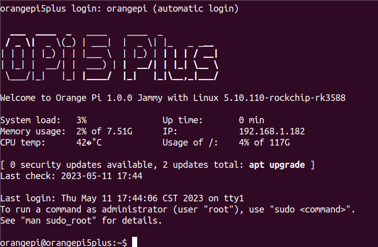
Use the following command to set the root user to automatically log in to the terminal
orangepi@orangepi:~$ sudo auto_login_cli.sh root
Use the following command to disable automatic login terminal
orangepi@orangepi:~$ sudo auto_login_cli.sh -d
Use the following command to set the orangepi user to automatically log in to the terminal again
orangepi@orangepi:~$ sudo auto_login_cli.sh orangepi

Instructions for automatic login of Linux desktop version system
After the desktop version system is started, it will automatically log in to the desktop without entering a password
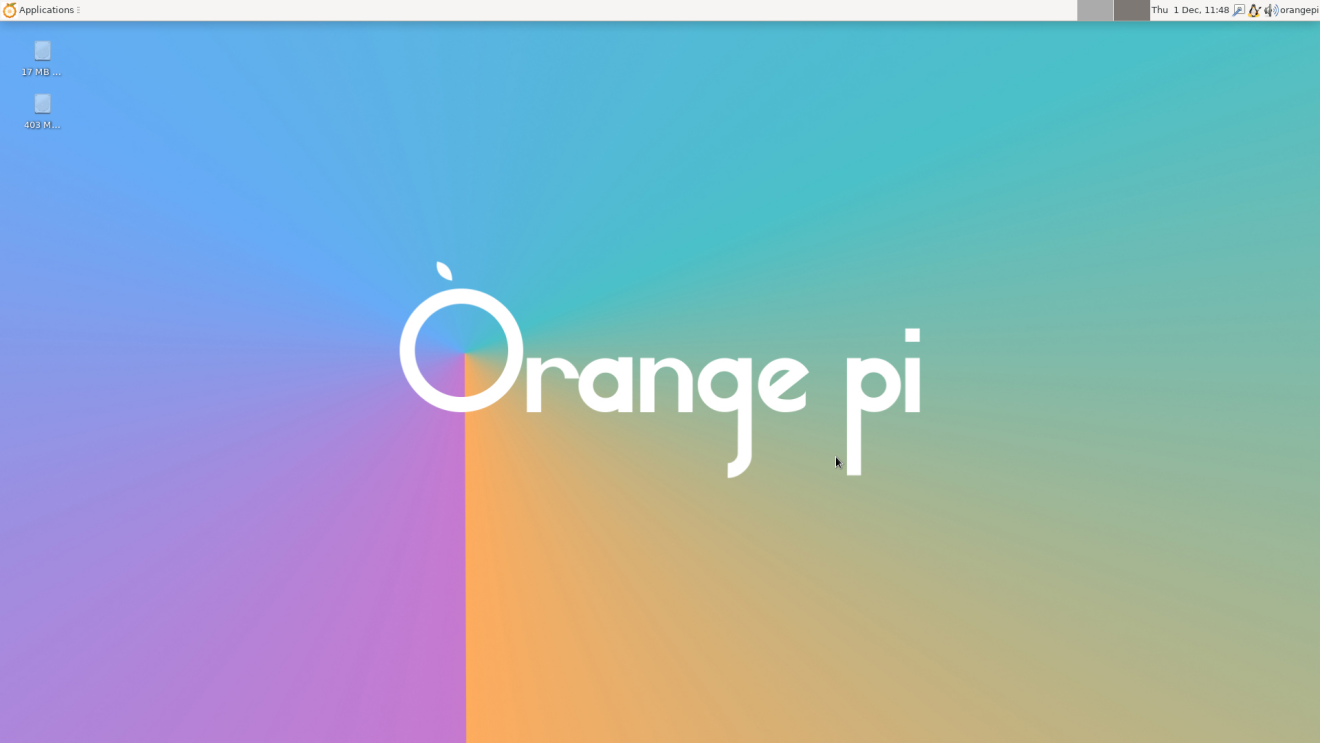
Run the following command to prohibit the desktop system from automatically logging into the desktop
orangepi@orangepi:~$ sudo disable_desktop_autologin.sh
Then restart the system and a login dialog box will appear, at which point a password is required to enter the system


The setting method of root user automatic login in Linux desktop version system
Execute the following command to set the desktop system to automatically log in as the root user
orangepi@orangepi:~$ sudo desktop_login.sh root
Then restart the system, it will automatically use the root user to log in to the desktop
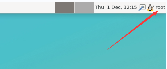
Note that if you log in to the desktop system as the root user, you cannot use pulseaudio in the upper right corner to manage audio devices.
Also note that this is not a bug, since pulseaudio is not allowed to run as root.
Execute the following command to set the desktop system to log in automatically with the orangepi user again
orangepi@orangepi:~$ sudo desktop_login.sh orangepi

The method of disabling the desktop in the Linux desktop version system
First enter the following command in the command line, please remember to add sudo permission
orangepi@orangepi:~$ sudo systemctl disable lightdm.service
Then restart the Linux system and you will find that the desktop will not be displayed
orangepi@orangepi:~$ sudo reboot
The steps to reopen the desktop are as follows:
First enter the following command in the command line, please remember to add sudo permission
orangepi@orangepi:~$ sudo systemctl start lightdm.service
orangepi@orangepi:~$ sudo systemctl enable lightdm.service
After selection, the monitor will display the desktop
Onboard LED Light Test Instructions
There is a red, green and blue three-color light on the development board, and its location is shown in the figure below:
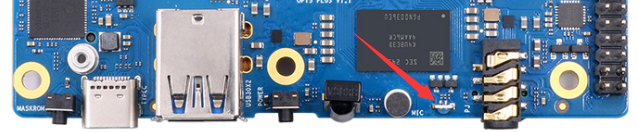
As long as the development board is powered on, the red LED light will always be on, which is controlled by the hardware and cannot be turned off by the software. The red LED light can be used to determine whether the power supply of the development board is turned on normally.
The green and blue LED lights will keep blinking after the kernel boots, which is controlled by software.
The method of setting the green light on and off and flashing is as follows:
Note that the following operations should be performed under the root user.
First enter the setting directory of the green light
root@orangepi:~# cd /sys/class/leds/green_led
The command to set the green light to stop flashing is as follows
root@orangepi:/sys/class/leds/green_led# echo none > trigger
The command to set the green light to be on is as follows
root@orangepi:/sys/class/leds/green_led# echo default-on > trigger
The command to set the green light to flash is as follows
root@orangepi:/sys/class/leds/green_led# echo heartbeat > trigger
The method of setting the blue light on and off and flashing is as follows:
Note that the following operations should be performed under the root user.
First enter the setting directory of the blue light
root@orangepi:~# cd /sys/class/leds/blue_led
The command to set the blue light to stop flashing is as follows
root@orangepi:/sys/class/leds/blue_led# echo none > trigger
The command to set the blue light to be on is as follows
root@orangepi:/sys/class/leds/blue_led# echo default-on > trigger
The command to set the blue light to flash is as follows
root@orangepi:/sys/class/leds/blue_led# echo heartbeat > trigger
If you don't want the LED light to flash after booting, you can use the following method to turn off the green light and blue light
First run orangepi-config, normal users remember to add sudo permission
orangepi@orangepi:~$ sudo orangepi-config
Then select System
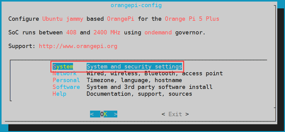
Then select Hardware

Then use the arrow keys of the keyboard to navigate to the position shown in the figure below, and then use the space to select the opi5plus-disable-leds configuration

Then select <Save> to save
Then select <Back>
Then select <Reboot> to restart the system to make the configuration take effect
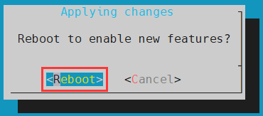
After restarting, you can see that only the red light on the development board is always on, and the green and blue lights will not flash


Network connection test
2.5G Ethernet port test
The development board has two 2.5G Ethernet ports, and the test methods for the two ports are the same. First, insert one end of the network cable into the Ethernet interface of the development board, and connect the other end of the network cable to the router, and ensure that the network is unimpeded.
After the system starts, it will automatically assign an IP address to the Ethernet card through DHCP without any other configuration.
The command to view the IP address in the Linux system of the development board is as follows:
orangepi@orangepi:~$ ip addr show
1: lo: <LOOPBACK,UP,LOWER_UP> mtu 65536 qdisc noqueue state UNKNOWN group default qlen 1000
link/loopback 00:00:00:00:00:00 brd 00:00:00:00:00:00
inet 127.0.0.1/8 scope host lo
valid_lft forever preferred_lft forever
inet6 ::1/128 scope host
valid_lft forever preferred_lft forever
2: enP3p49s0: <BROADCAST,MULTICAST,UP,LOWER_UP> mtu 1500 qdisc mq state UP group default qlen 1000
link/ether 00:e0:4c:68:00:26 brd ff:ff:ff:ff:ff:ff
inet 192.168.1.245/24 brd 192.168.1.255 scope global dynamic noprefixroute enP3p49s0
valid_lft 42537sec preferred_lft 42537sec
inet6 fe80::9005:95ac:b9c0:2beb/64 scope link noprefixroute
valid_lft forever preferred_lft forever
3: enP4p65s0: <BROADCAST,MULTICAST,UP,LOWER_UP> mtu 1500 qdisc mq state UP group default qlen 1000
link/ether 00:e0:4c:68:00:27 brd ff:ff:ff:ff:ff:ff
inet 192.168.1.247/24 brd 192.168.1.255 scope global dynamic noprefixroute enP4p65s0
valid_lft 43179sec preferred_lft 43179sec
inet6 fe80::62b5:dc5e:728e:39a3/64 scope link noprefixroute
valid_lft forever preferred_lft forever
When using ifconfig to view the IP address, if the following information is prompted, it is because sudo is not added. The correct command is: sudo ifconfig
orangepi@orangepi:~$ ifconfig
Command 'ifconfig' is available in the following places
* /sbin/ifconfig
* /usr/sbin/ifconfig
The command could not be located because '/sbin:/usr/sbin' is not included in the PATH environment variable.
This is most likely caused by the lack of administrative privileges associated with your user account.
ifconfig: command not found
There are three ways to check the IP address after the development board starts:
- Connect the HDMI display, then log in to the system and use the ip addr show command to view the IP address
- Enter the ip addr show command in the debugging serial terminal to view the IP address
- If there is no debugging serial port and no HDMI display, you can also check the IP address of the development board's network port through the router's management interface. However, in this method, some people often cannot see the IP address of the development board normally. If you can't see it, the debug method looks like this:
First check whether the Linux system has started normally. If the three-color light on the development board is flashing, it is generally started normally. If only the red light is on, it means that the system has not started normally;
Check whether the network cable is plugged in tightly, or try another network cable;
Try another router (I have encountered many problems with the router, such as the router cannot assign the IP address normally, or the IP address has been
assigned normally but cannot be seen in the router);
If there is no router to replace, you can only connect to an HDMI display or use the debugging serial port to check the IP address.
In addition, it should be noted that the development board DHCP automatically assigns an IP address without any settings.
The command to test the network connectivity is as follows, the ping command can be interrupted through the shortcut key of Ctrl+C
orangepi@orangepi:~$ ping www.baidu.com -I enP4p65s0 #Test command for one of the network ports
orangepi@orangepi:~$ ping www.baidu.com -I enP3p49s0 #Test command of another network port
PING www.a.shifen.com (14.119.104.254) from 192.168.1.182 enP3p49s0: 56(84) bytes of data.
64 bytes from 14.119.104.254 (14.119.104.254): icmp_seq=1 ttl=56 time=6.26 ms
64 bytes from 14.119.104.254 (14.119.104.254): icmp_seq=6 ttl=56 time=5.69 ms
^C
--- www.a.shifen.com ping statistics ---
6 packets transmitted, 6 received, 0% packet loss, time 5008ms
rtt min/avg/max/mdev = 5.671/5.859/6.264/0.202 ms
WIFI connection test
|
First of all, please note that there is no WIFI module on the Orange Pi 5 Plus development board, and an external PCIe network card or USB network card is required to use the WIFI function. For instructions on using the external PCIe network card, please refer to the section on how to use the PCIe WIFI6+Bluetooth module. For instructions on using the external USB network card, please refer to the USB wireless network card test section. Please do not connect to WIFI by modifying the /etc/network/interfaces configuration file. There will be problems connecting to the WIFI network in this way. |
|
Please do not connect to WIFI by modifying the /etc/network/interfaces configuration file. There will be problems connecting to the WIFI network in this way. |
The server image connects to WIFI through commands
|
When the development board is not connected to Ethernet, not connected to HDMI display, but only connected to the serial port, it is recommended to use the commands demonstrated in this section to connect to the WIFI network. Because nmtui can only display characters in some serial port software (such as minicom), and cannot display the graphical interface normally. Of course, if the development board is connected to an Ethernet or HDMI display, you can also use the commands demonstrated in this section to connect to the WIFI network.
|
First log in to the linux system, there are the following three ways
If the development board is connected with a network cable, you can remotely log in to the Linux system through ssh
If the development board is connected to the debugging serial port, you can use the serial port terminal to log in to the Linux system
If the development board is connected to the HDMI display, you can log in to the linux system through the HDMI display terminal
First use the nmcli dev wifi command to scan the surrounding WIFI hotspots
orangepi@orangepi:~$ nmcli dev wifi
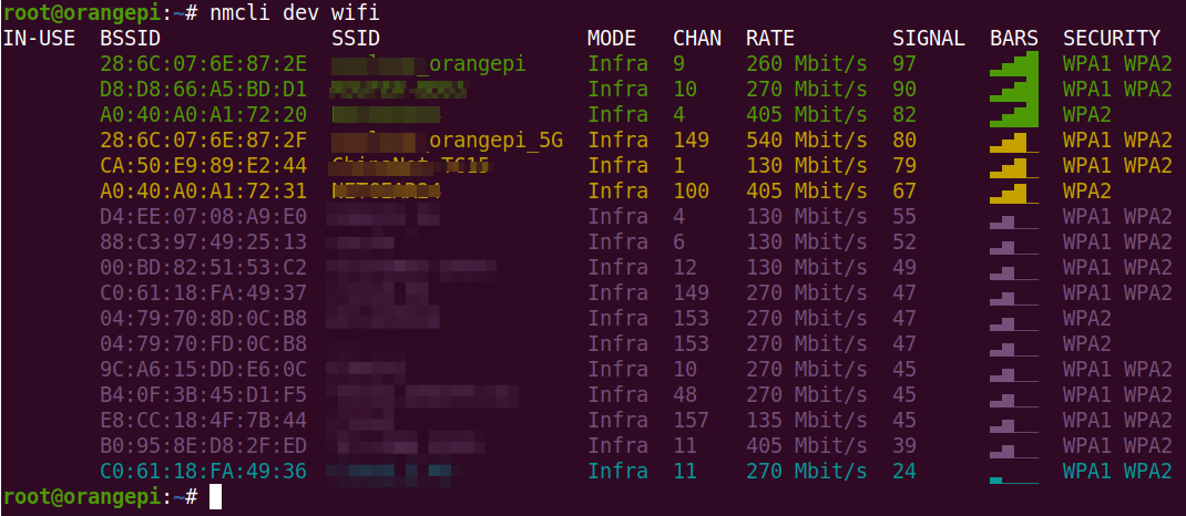
Then use the nmcli command to connect to the scanned WIFI hotspot, where:
wifi_name needs to be replaced with the
wifi_passwd needs to be replaced with the password of the WIFI hotspot you want to connect to
orangepi@orangepi:~$ nmcli dev wifi connect wifi_name password wifi_passwd
Device 'wlan0' successfully activated with 'cf937f88-ca1e-4411-bb50-61f402eef293'.
Through the ip addr show wlan0 command, you can view the IP address of wifi
The device node names of WIFI are not necessarily all wlan0, please refer to what you actually see.
orangepi@orangepi:~$ ip addr show wlan0
11: wlan0: <BROADCAST,MULTICAST,UP,LOWER_UP> mtu 1500 qdisc pfifo_fast state UP group default qlen 1000
link/ether 23:8c:d6:ae:76:bb brd ff:ff:ff:ff:ff:ff
inet 192.168.1.11/24 brd 192.168.1.255 scope global dynamic noprefixroute wlan0
valid_lft 259192sec preferred_lft 259192sec
inet6 240e:3b7:3240:c3a0:c401:a445:5002:ccdd/64 scope global dynamic noprefixroute
valid_lft 259192sec preferred_lft 172792sec
inet6 fe80::42f1:6019:a80e:4c31/64 scope link noprefixroute
valid_lft forever preferred_lft forever
Use the ping command to test the connectivity of the wifi network, and the ping command can be interrupted through the shortcut key Ctrl+C
The device node names of WIFI are not necessarily all wlan0, please refer to what you actually see.
orangepi@orangepi:~$ ping www.orangepi.org -I wlan0
PING www.orangepi.org (182.92.236.130) from 192.168.1.49 wlan0: 56(84) bytes of data.
64 bytes from 182.92.236.130 (182.92.236.130): icmp_seq=1 ttl=52 time=43.5 ms
64 bytes from 182.92.236.130 (182.92.236.130): icmp_seq=2 ttl=52 time=41.3 ms
64 bytes from 182.92.236.130 (182.92.236.130): icmp_seq=3 ttl=52 time=44.9 ms
64 bytes from 182.92.236.130 (182.92.236.130): icmp_seq=4 ttl=52 time=45.6 ms
64 bytes from 182.92.236.130 (182.92.236.130): icmp_seq=5 ttl=52 time=48.8 ms
^C
--- www.orangepi.org ping statistics ---
5 packets transmitted, 5 received, 0% packet loss, time 4006ms
rtt min/avg/max/mdev = 41.321/44.864/48.834/2.484 ms

The server image connects to WIFI in a graphical way
First log in to the linux system, there are the following three ways
If the development board is connected with a network cable, you can remotely log in to the Linux system through ssh
If the development board is connected to the debugging serial port, you can use the serial port terminal to log in to the linux system (please use MobaXterm for the serial port software, and minicom cannot display the graphical interface)
If the development board is connected to the HDMI display, you can log in to the linux system through the terminal displayed on the HDMI
Then enter the nmtui command in the command line to open the wifi connection interface
orangepi@orangepi:~$ nmtui
Enter the nmtui command to open the interface as shown below
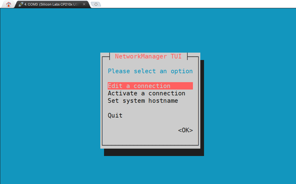
Select Activate a connect and press Enter
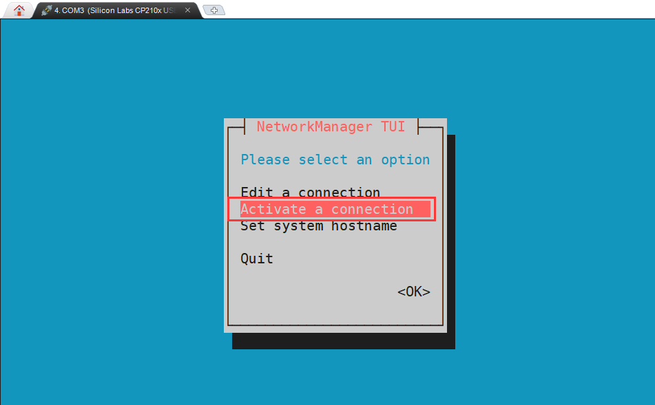
Then you can see all the searched WIFI hotspots
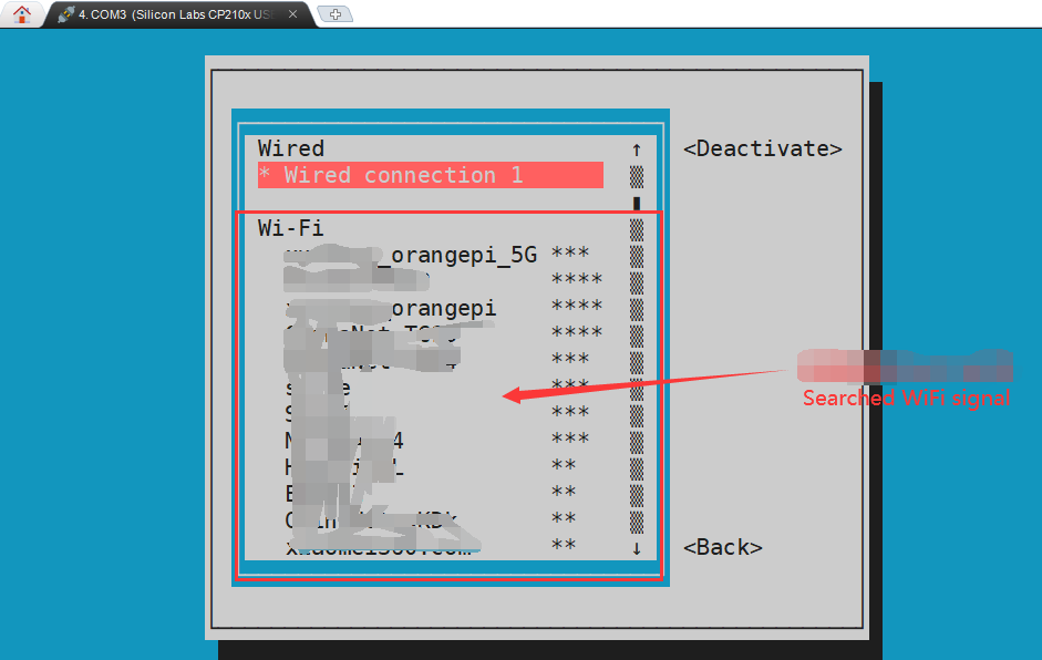
Select the WIFI hotspot you want to connect to, then use the Tab key to position the cursor on Activate and press Enter
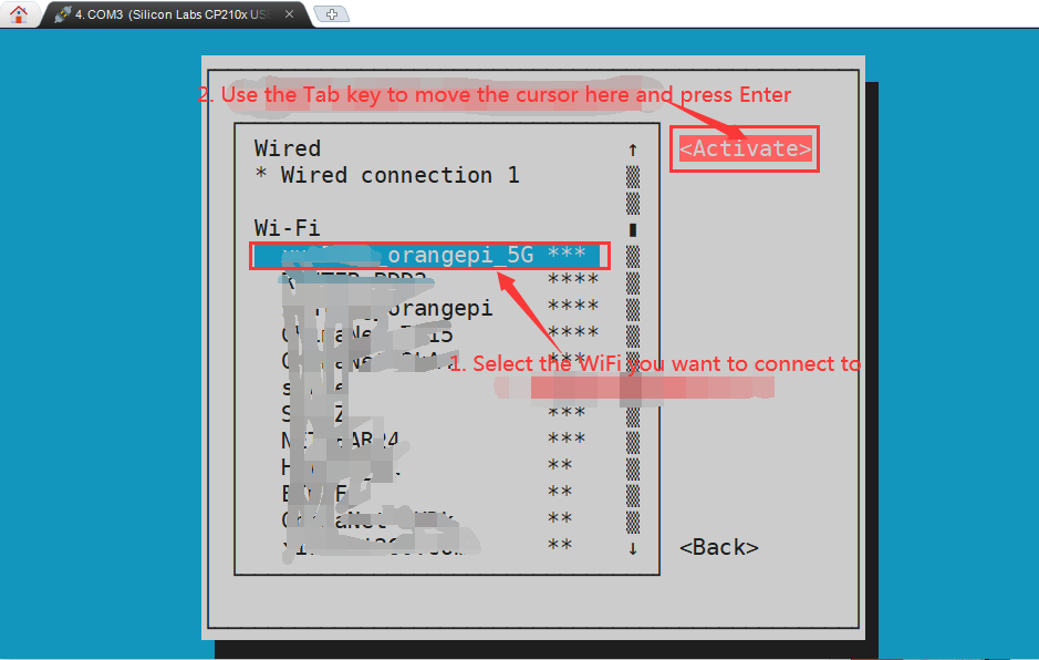
Then a dialog box for entering a password will pop up, enter the corresponding password in Password and press Enter to start connecting to WIFI
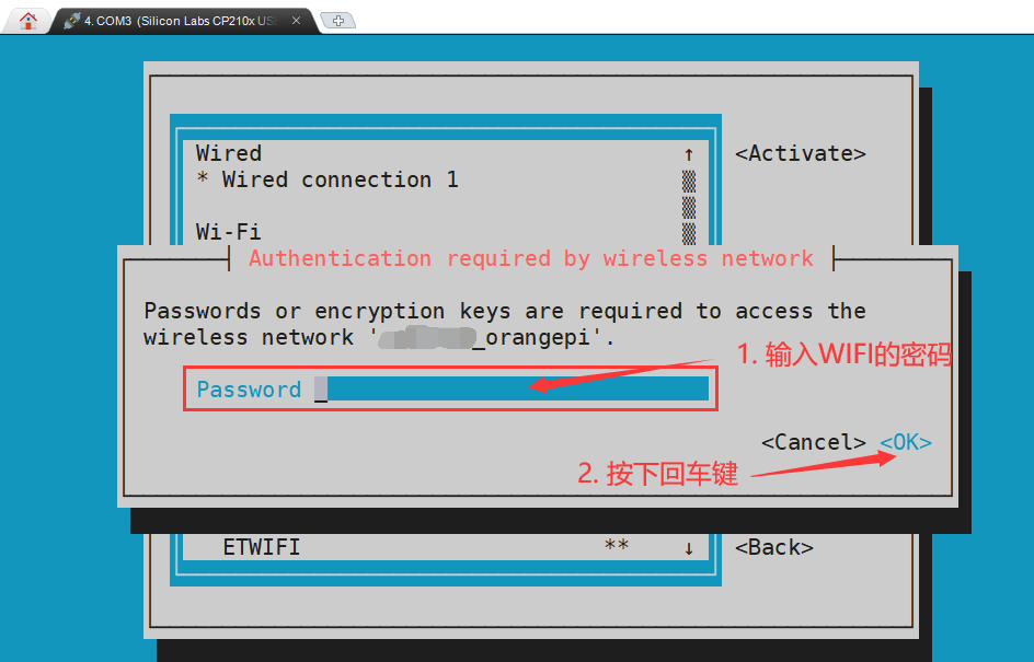
After the WIFI connection is successful, a "*" will be displayed in front of the connected WIFI name
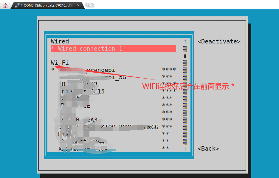
You can view the IP address of wifi through the ip addr show wlan0 command
The device node names of WIFI are not necessarily all wlan0, please refer to what you actually see.
orangepi@orangepi:~$ ip addr show wlan0
11: wlan0: <BROADCAST,MULTICAST,UP,LOWER_UP> mtu 1500 qdisc pfifo_fast state UP group default qlen 1000
link/ether 24:8c:d3:aa:76:bb brd ff:ff:ff:ff:ff:ff
inet 192.168.1.11/24 brd 192.168.1.255 scope global dynamic noprefixroute wlan0
valid_lft 259069sec preferred_lft 259069sec
inet6 240e:3b7:3240:c4a0:c401:a445:5002:ccdd/64 scope global dynamic noprefixroute
valid_lft 259071sec preferred_lft 172671sec
inet6 fe80::42f1:6019:a80e:4c31/64 scope link noprefixroute
valid_lft forever preferred_lft forever
Use the ping command to test the connectivity of the wifi network, and the ping command can be interrupted through the shortcut key Ctrl+C
The device node names of WIFI are not necessarily all wlan0, please refer to what you actually see.
orangepi@orangepi:~$ ping www.orangepi.org -I wlan0
PING www.orangepi.org (182.92.236.130) from 192.168.1.49 wlan0: 56(84) bytes of data.
64 bytes from 182.92.236.130 (182.92.236.130): icmp_seq=1 ttl=52 time=43.5 ms
64 bytes from 182.92.236.130 (182.92.236.130): icmp_seq=2 ttl=52 time=41.3 ms
64 bytes from 182.92.236.130 (182.92.236.130): icmp_seq=3 ttl=52 time=44.9 ms
64 bytes from 182.92.236.130 (182.92.236.130): icmp_seq=4 ttl=52 time=45.6 ms
64 bytes from 182.92.236.130 (182.92.236.130): icmp_seq=5 ttl=52 time=48.8 ms
^C
--- www.orangepi.org ping statistics ---
5 packets transmitted, 5 received, 0% packet loss, time 4006ms
rtt min/avg/max/mdev = 41.321/44.864/48.834/2.484 ms


Test method of desktop image
Click the network configuration icon in the upper right corner of the desktop (please do not connect the network cable when testing WIFI)
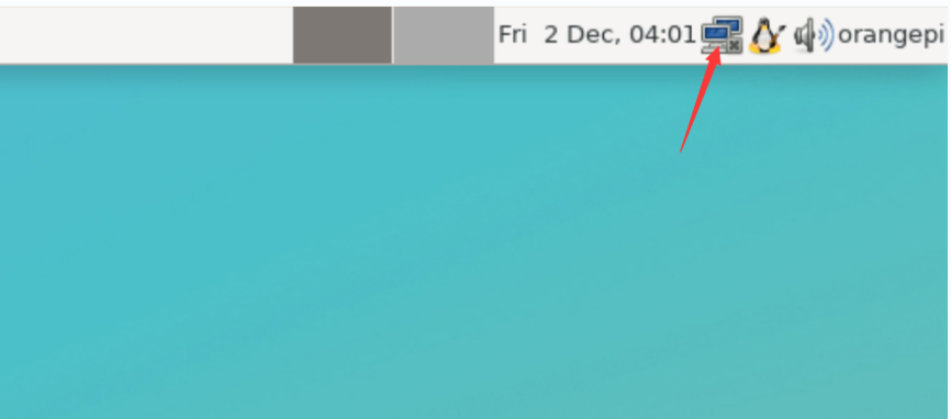
Click More networks in the pop-up drop-down box to see all scanned WIFI hotspots, and then select the WIFI hotspot you want to connect to

Then enter the password of the WIFI hotspot, and then click Connect to start connecting to WIFI
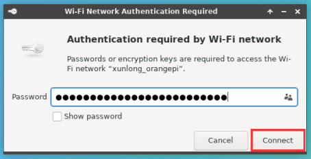
After connecting to WIFI, you can open the browser to check whether you can access the Internet. The entrance of the browser is shown in the figure below
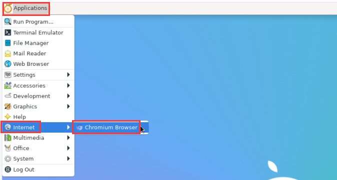
If you can open other web pages after opening the browser, it means that the WIFI connection is normal
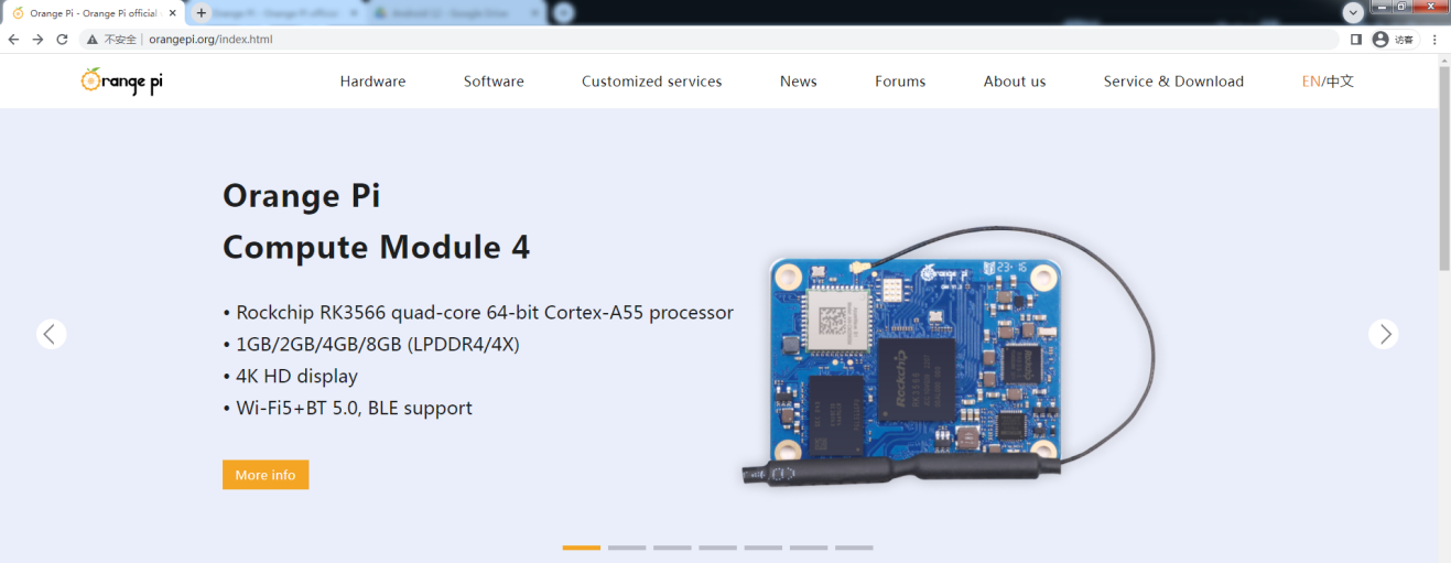


How to set a static IP address
|
Please do not set a static IP address by modifying the /etc/network/interfaces configuration file. |
Use the nmtui command to set a static IP address
First run the nmtui command
orangepi@orangepi:~$ nmtui
Then select Edit a connection and press Enter
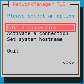
Then select the network interface that needs to set a static IP address, such as setting the static IP address of the Ethernet interface to select Wired connection 1 or Wired connection 2
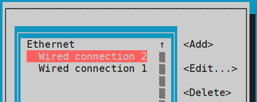
Then select Edit via the Tab key and press the Enter key
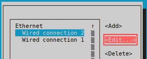
Then use the Tab key to move the cursor to the <Automatic> position shown in the figure below to configure IPv4
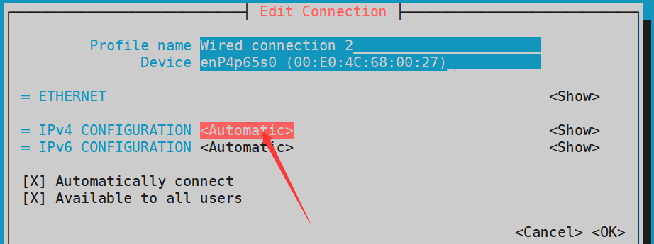
Then press Enter, select Manual through the up and down arrow keys, and press Enter to confirm
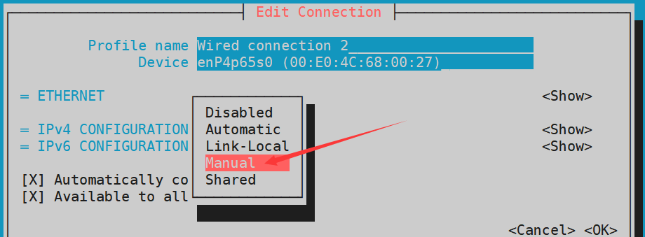
The display after selection is shown in the figure below
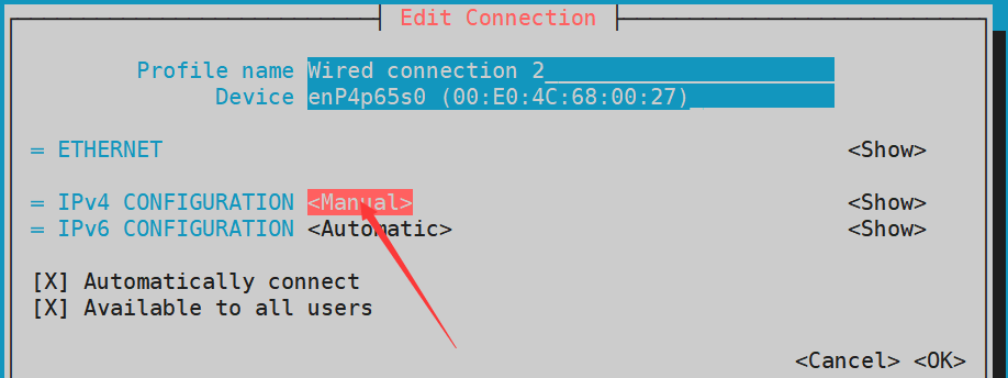
Then move the cursor to <Show> via the Tab key
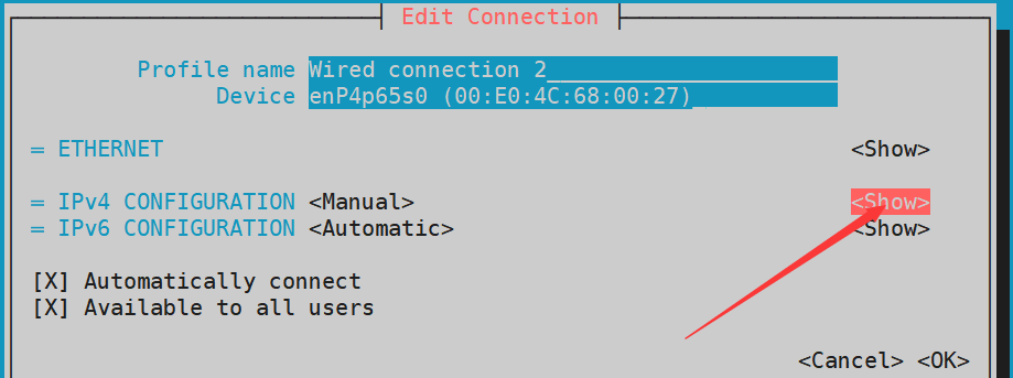
Then press Enter, and the following setting interface will pop up after entering
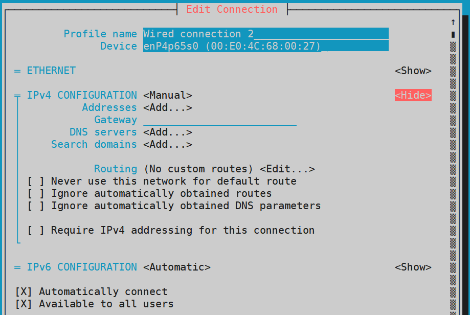
Then you can set the IP address (Addresses), gateway (Gateway) and DNS server address in the position shown in the figure below (there are many other setting options in it, please explore by yourself), please set according to your specific needs, The values set in the image below are just an example
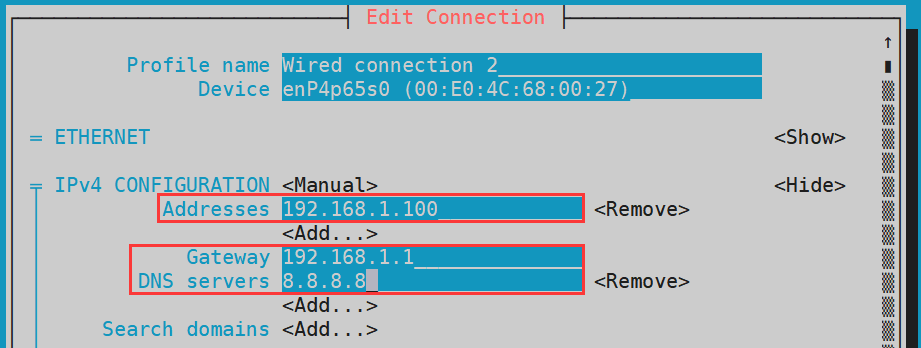
After setting, move the cursor to <OK> in the lower right corner, and press Enter to confirm
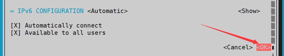
Then click <Back> to return to the previous selection interface
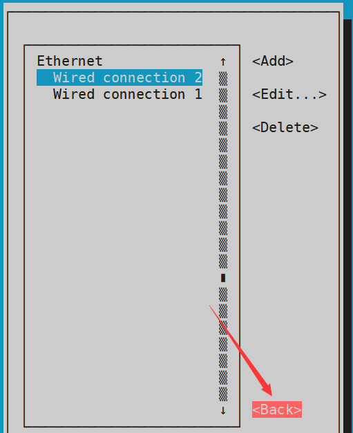
Then select Activate a connection, then move the cursor to <OK>, and finally click Enter
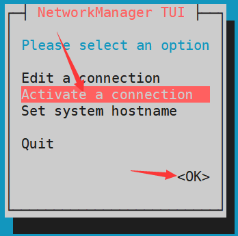
Then select the network interface that needs to be set, such as Wired connection 2, then move the cursor to <Deactivate>, and press the Enter key to disable Wired connection 2
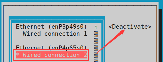
Then re-select and enable Wired connection 2, so that the static IP set earlier will take effect
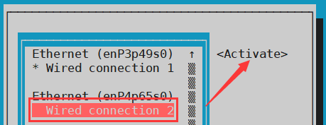
Then you can exit nmtui through the <Back> and Quit buttons
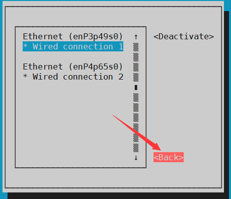
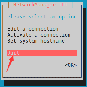
Then through ip addr show, you can see that the IP address of the network port has changed to the static IP address set earlier
orangepi@orangepi:~$ ip addr show enP4p65s0
3: eth0: <BROADCAST,MULTICAST,UP,LOWER_UP> mtu 1500 qdisc pfifo_fast state UP group default qlen 1000
link/ether 5e:ac:14:a5:92:b3 brd ff:ff:ff:ff:ff:ff
inet 192.168.1.100/24 brd 192.168.1.255 scope global noprefixroute enP4p65s0
valid_lft forever preferred_lft forever
inet6 241e:3b8:3240:c3a0:e269:8305:dc08:135e/64 scope global dynamic noprefixroute
valid_lft 259149sec preferred_lft 172749sec
inet6 fe80::957d:bbbe:4928:3604/64 scope link noprefixroute
valid_lft forever preferred_lft forever
Then you can test the connectivity of the network to check whether the IP address is configured OK, and the ping command can be interrupted through the shortcut key Ctrl+C
orangepi@orangepi:~$ ping 192.168.1.47 -I enP4p65s0
PING 192.168.1.47 (192.168.1.47) from 192.168.1.188 enP4p65s0: 56(84) bytes of data.
64 bytes from 192.168.1.47: icmp_seq=1 ttl=64 time=0.233 ms
64 bytes from 192.168.1.47: icmp_seq=2 ttl=64 time=0.263 ms
^C
--- 192.168.1.47 ping statistics ---
5 packets transmitted, 5 received, 0% packet loss, time 4042ms
rtt min/avg/max/mdev = 0.233/0.262/0.275/0.015 ms


Use the nmcli command to set a static IP address
If you want to set the static IP address of the network port, please insert the network cable into the development board first. If you need to set the static IP address of WIFI, please connect the WIFI first, and then start to set the static IP address
Then use the nmcli con show command to view the name of the network device, as shown below, Wired connection 1 and Wired connection 2 are the names of the Ethernet interfaces
orangepi@orangepi:~$ nmcli con show
NAME UUID TYPE DEVICE
Wired connection 1 c043c817-1156-3b72-a559-9a8cd642bf70 ethernet enP3p49s0
Wired connection 2 6f74598a-ccc6-358b-be05-87eaf34df930 ethernet enP4p65s0
Then enter the following command, where
"Wired connection 1" means to set the static IP address of the Ethernet port. If you need to set the static IP address of other network ports, please modify it to the name corresponding to the corresponding network interface (you can get it through the nmcli con show command)
ipv4.addresses is followed by the static IP address to be set, which can be modified to the value you want to set
ipv4.gateway represents the address of the gateway
orangepi@orangepi:~$ nmcli con mod "Wired connection 1" \
ipv4.addresses "192.168.1.110" \
ipv4.gateway "192.168.1.1" \
ipv4.dns "8.8.8.8" \
ipv4.method "manual"
Then restart the linux system
orangepi@orangepi:~$ sudo reboot
Then re-enter the linux system and use the ip addr show command to see that the IP address has been set to the desired value
orangepi@orangepi:~$ ip addr show
2: enP3p49s0: <BROADCAST,MULTICAST,UP,LOWER_UP> mtu 1500 qdisc mq state UP group default qlen 1000
link/ether 00:e0:4c:68:00:26 brd ff:ff:ff:ff:ff:ff
inet 192.168.1.110/32 scope global noprefixroute enP3p49s0
valid_lft forever preferred_lft forever
inet6 fe80::9005:95ac:b9c0:2beb/64 scope link noprefixroute
valid_lft forever preferred_lft forever
How to use E-Key PCIe WIFI6+Bluetooth module
- First you need to buy a PCIe WIFI6+Bluetooth module
S/N Model Physical picture Supported OS 1 AX200 (PCIE+USB port)
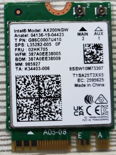
Debian Ubuntu
OpenWRT
OPi OS Arch
2 AX210 (PCIE+USB port)
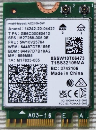
Debian Ubuntu
OpenWRT
OPi OS Arch
3 RTL8852BE (PCIE+USB port)
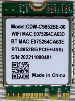
Debian Ubuntu
Android12
OPi OS Arch
OPi OS Droid


Then insert the module into the M.2 E-Key interface of the development board and fix it. The position is shown in the figure below:
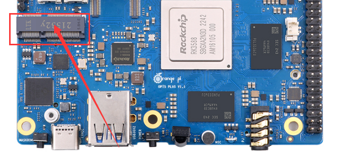
Then use the lspci command, if you can see the information of the WIFI module, it means that the module is in good contact
AX200 displays as follows
orangepi@orangepi:~$ lspci | grep "Network"
0002:21:00.0 Network controller: Intel Corporation Wi-Fi 6 AX200 (rev 1a)
AX210 displays as follows
orangepi@orangepi:~$ lspci | grep "Network"
0002:21:00.0 Network controller: Intel Corporation Wi-Fi 6 AX210/AX211/AX411 160MHz (rev 1a)
RTL8852 display as shown below
orangepi@orangepi:~$ lspci | grep "Network"
0002:21:00.0 Network controller: Intel Corporation Wi-Fi 6 AX200 (rev 1a)
Then use the following command to see that there will be an additional WIFI device node
[orangepi@orangepi ~]$ ip a
For the WIFI connection and test method, please refer to the WIFI connection test section, and will not repeat them here.
For the test method of Bluetooth, please refer to the section on Bluetooth usage, so I won’t go into details here.

SSH remote login development board
|
Linux systems enable ssh remote login by default and allow the root user to log in to the system. Before logging in with ssh, you first need to ensure that the Ethernet or wifi network is connected, and then use the ip addr command or check the router to obtain the IP address of the development board. |
SSH remote login development board under Ubuntu
- Obtain the IP address of the development board
- Then you can remotely log in to the linux system through the ssh command
test@test:~$ ssh root@192.168.1.xxx (Need to be replaced with the IP address of the development board)
root@192.168.1.xx's password: (Enter the password here, the default password is orangepi)
Note that when entering the password, the specific content of the entered password will not be displayed on the screen, please do not think that there is any fault, just press Enter after inputting.
If you are prompted to refuse the connection, as long as you are using the image provided by Orange Pi, please do not suspect that the password orangepi is wrong, but look for other reasons.
After successfully logging in to the system, the display is as shown in the figure below
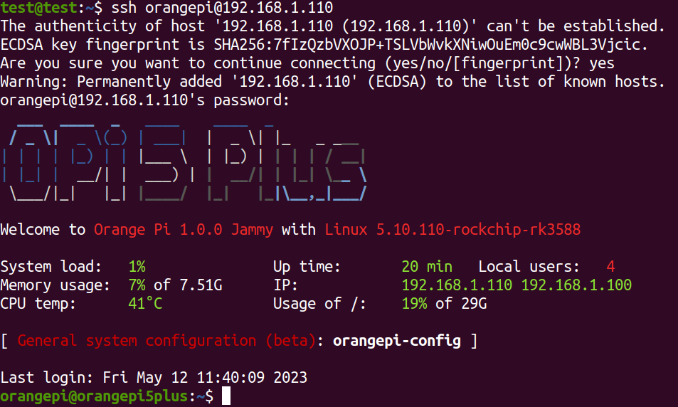
If ssh fails to log in to the linux system normally, first check whether the IP address of the development board can be pinged. If the ping is ok, you can log in to the linux system through the serial port or HDMI display and then enter the following command on the development board and try again. Is it possible to connect:
root@orangepi:~# reset_ssh.sh
If it still doesn't work, try to reset the system.

SSH remote login development board under Windows
First obtain the IP address of the development board
Under Windows, you can use MobaXterm to remotely log in to the development board, first create a new ssh session
Open Session
Then select SSH in Session Setting
Then enter the IP address of the development board in the Remote host
Then enter the user name root or orangepi of the linux system in Specify username
Finally click OK
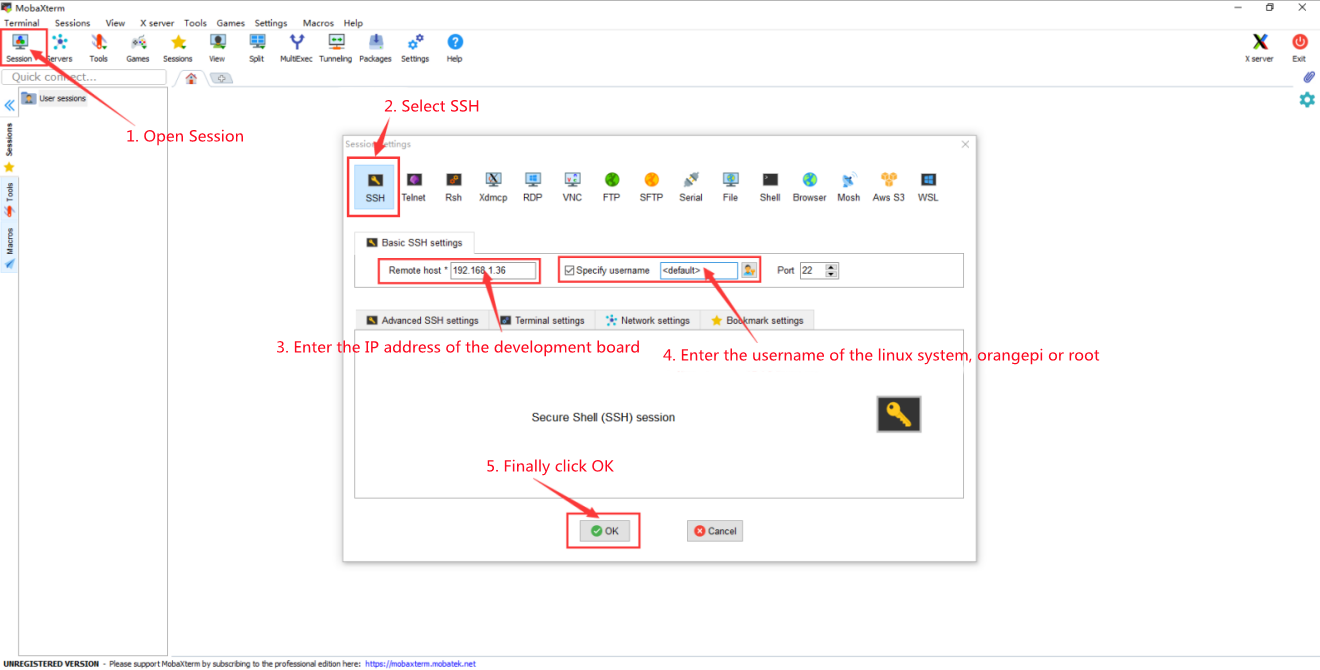
Then you will be prompted to enter a password. The default passwords for root and orangepi users are orangepi
Note that when entering the password, the specific content of the entered password will not be displayed on the screen, please do not think that there is any fault, just press Enter after inputting.
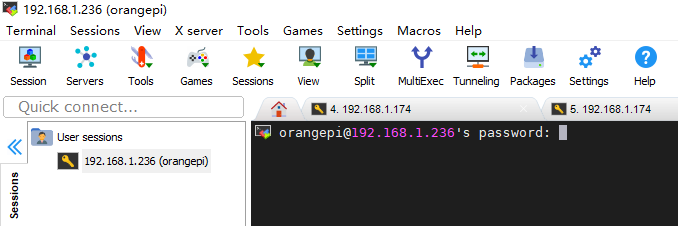


- After successfully logging in to the system, the display is as shown in the figure below

How to use ADB
How to use network adb
After the system starts, please confirm that adbd has been started
orangepi@orangepi:~$ ps -ax | grep "adbd"
808 ? Sl 0:00 /usr/bin/adbd
3707 ttyFIQ0 S+ 0:00 grep --color=auto adbd
Then check the IP address of the development board and write it down
Then install the adb tool on the Ubuntu PC
test@test:~$ sudo apt-get update
test@test:~$ sudo apt-get install -y adb
Then use the following command to connect to the network adb
- daemon not running; starting now at tcp:5037
- daemon started successfully
|
test@test:~$ adb connect 192.168.1.xx:5555 #Please replace the IP address with the IP address of the development board connected to 192.168.1.xx:5555 test@test:~$ adb devices List of devices attached 192.168.1.xx:5555 device |
- Then use the following command to log in to the linux system of the development board
|
test@test:~$ adb shell root@orangepi5plus:/# <--- After seeing this prompt, it means that you have successfully logged in to the development board |
The command to upload files to the development board using adb is as follows
test@test:~$ adb push filename /root
filename: 1 file pushed. 3.7 MB/s (1075091 bytes in 0.277s)
The command to restart the development board using adb is as follows
test@test:~$ adb reboot
If there is no adb tool in your Windows system, you can use the adb program in the RKDevTool software (this software is useful in the section on how to use RKDevTool to burn the Linux image to the TF card).
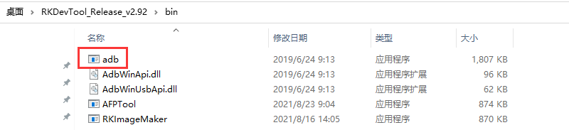
An example using adb in Windows looks like this:
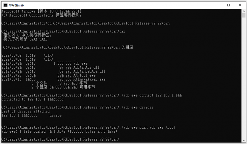


adb3.9.2. Use type-c data cable to connect to adb
First prepare a good quality Type-C data cable
Then connect the development board and Ubuntu PC through the Type-C data cable. The position of the Type-C interface of the development board is shown in the figure below:
Then run the following command to set the Type-C interface to device mode
orangepi@orangepi:~$ sudo set_device.sh
If the set_device.sh script does not exist in the Linux system, please use the following command directly:
orangepi@orangepi:~$ sudo bash -c "echo device > /sys/kernel/debug/usb/fc000000.usb/mode"
orangepi@orangepi:~$ sudo systemctl restart usbdevice
Then please confirm that adbd has been started
orangepi@orangepi:~$ ps -ax | grep "adbd"
808 ? Sl 0:00 /usr/bin/adbd
3707 ttyFIQ0 S+ 0:00 grep --color=auto adbd
Then install the adb tool on the Ubuntu PC
test@test:~$ sudo apt-get update
test@test:~$ sudo apt-get install -y adb
Then use the following command to check whether the adb device is recognized
|
test@test:~$ adb devices List of devices attached e0f9f71bc343c305 device |
- Then use the following command to log in to the linux system of the development board
|
test@test:~$ adb shell root@orangepi5plus:/# <--- After seeing this prompt, it means that you have successfully logged in to the development board |
The command to upload files to the development board using adb is as follows
test@test:~$ adb push filename /root
filename: 1 file pushed. 3.7 MB/s (1075091 bytes in 0.277s)
|
If there is no adb tool in your Windows system, you can use the adb program in the RKDevTool software (this software is useful in the section on how to use RKDevTool to burn the Linux image to the TF card).
An example using adb in Windows looks like this:
|

The method of uploading files to the Linux system of the development board
How to upload files to the development board Linux system in Ubuntu PC
How to upload files using the scp command
Use the scp command to upload files from the Ubuntu PC to the Linux system on the development board. The specific commands are as follows
file_path: need to be replaced with the path of the file to be uploaded
orangepi: It is the user name of the Linux system of the development board, and it can also be replaced with other ones, such as root
192.168.xx.xx: It is the IP address of the development board, please modify it according to the actual situation
/home/orangepi: The path in the Linux system of the development board, which can also be modified to other paths
test@test:~$ scp file_path orangepi@192.168.xx.xx:/home/orangepi/
If you want to upload a folder, you need to add the -r parameter
test@test:~$ scp -r dir_path orangepi@192.168.xx.xx:/home/orangepi/
There are more usages of scp, please use the following command to view the man manual
|
test@test:~$ man scp |
How to upload files using filezilla
First install filezilla in Ubuntu PC
test@test:~$ sudo apt install -y filezilla
Then use the following command to open filezilla
test@test:~$ filezilla
The interface after filezilla is opened is as follows, at this time, the display under the remote site on the right is empty
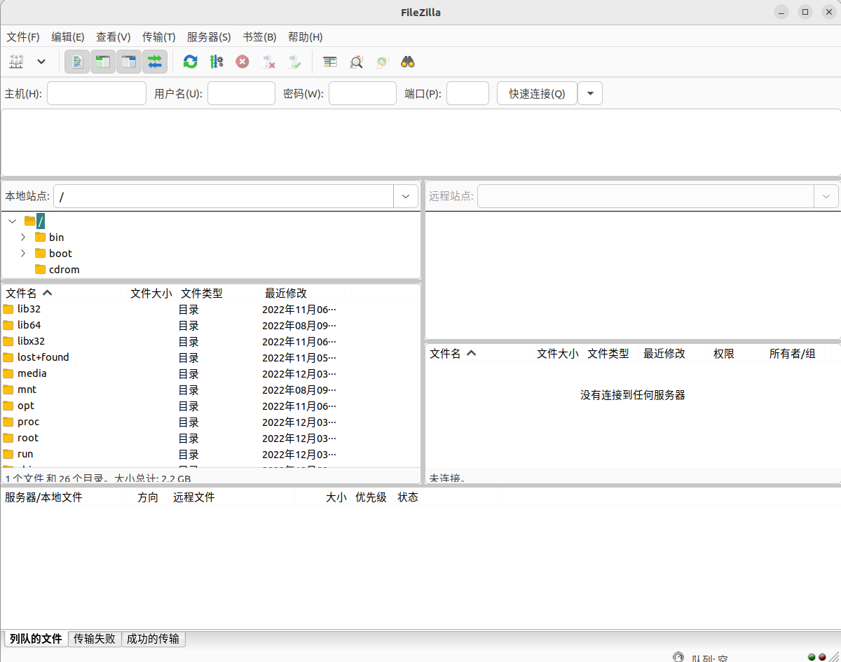
The method of connecting the development board is shown in the figure below


Then choose to save the password, and then click OK
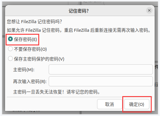
Then choose to always trust this host, and then click OK


- After the connection is successful, you can see the directory structure of the development board linux file system on the right side of the filezilla software

- Then select the path to be uploaded to the development board on the right side of the filezilla software, and then select the file to be uploaded on the Ubuntu PC on the left side of the filezilla software, then click the right mouse button, and then click the upload option to start uploading the file to the development board bingo.

After the upload is complete, you can go to the corresponding path in the Linux system of the development board to view the uploaded file
The method of uploading a folder is the same as that of uploading a file, so I won't go into details here
The method of uploading files to the development board Linux system in Windows PC
How to upload files using filezilla
First download the installation file of the Windows version of the filezilla software, the download link is as follows
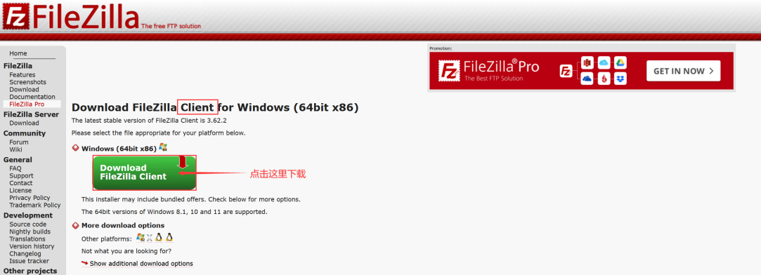
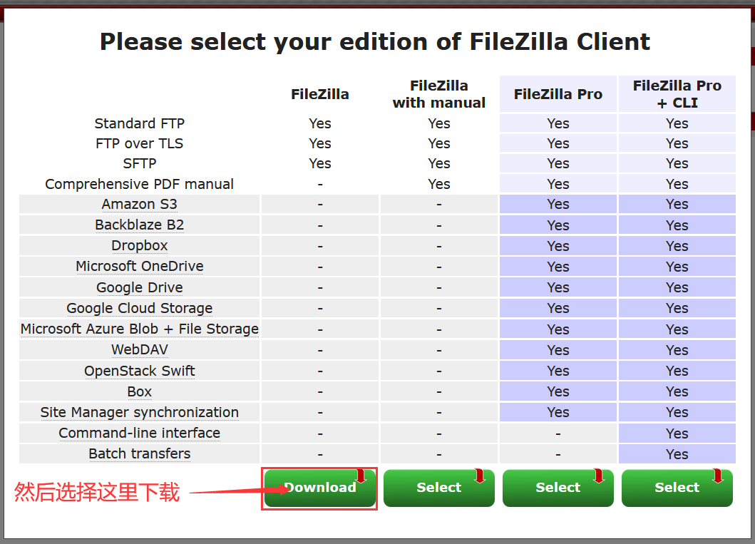


The downloaded installation package is as follows, and then double-click to install directly
FileZilla_Server_1.5.1_win64-setup.exe
During the installation process, please select Decline on the following installation interface, and then select Next>
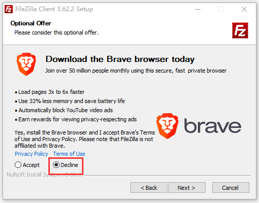

- The interface after filezilla is opened is as follows, at this time, the display under the remote site on the right is empty

- The method of connecting the development board is shown in the figure below:
- Then choose to save the password, and then click OK

- Then choose to always trust this host, and then click OK

- After the connection is successful, you can see the directory structure of the development board linux file system on the right side of the filezilla software

- Then select the path to be uploaded to the development board on the right side of the filezilla software, and then select the file to be uploaded on the Windows PC on the left side of the filezilla software, then click the right mouse button, and then click the upload option to start uploading the file to the development board bingo

After the upload is complete, you can go to the corresponding path in the Linux system of the development board to view the uploaded file
The method of uploading folders is the same as that of uploading files, so I won’t go into details here.
HDMI test
HDMI test
There are two HDMI output interfaces on the development board, and their locations are shown in the figure below:
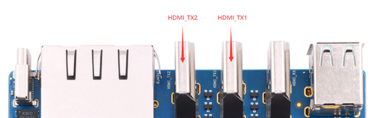
By default, the Linux system configures HDMI_TX1 to support 8K display, and HDMI_TX2 supports only 4K display by default (only one HDMI_TX interface can support 8K display at a time). If you want to set HDMI_TX2 to support 8K display, please follow the steps below:
First run orangepi-config, normal users remember to add > sudo permission
orangepi@orangepi:~$ sudo orangepi-config
Then select System

Then select Hardware
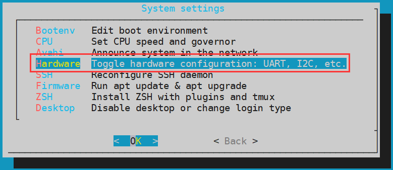
Then use the arrow keys of the keyboard to navigate to the > position shown in the figure below, and then use the space > to select hdmi2-8k configuration

Then select <Save> to save

Then select <Back>

Then select <Reboot> to restart the system to make the > configuration take effect

Then use HDMI to HDMI cable to connect Orange Pi development board and HDMI display
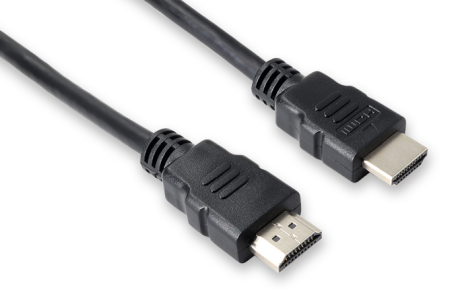
Note, if you want to connect a 4K or 8K display, please make sure that the HDMI cable supports 4K or 8K video display.
After starting the linux system, if the HDMI display has image output, it means that the HDMI interface is in normal use


|
Note that although many laptops have an HDMI interface, the HDMI interface of the notebook generally only has the output function, and does not have the function of HDMI in, that is to say, the HDMI output of the development board cannot be displayed on the screen of the notebook. When you want to connect the HDMI of the development board to the HDMI port of the laptop, please make sure that your laptop supports the HDMI in function. |
|
When the HDMI is not displayed, please check whether the HDMI cable is plugged in tightly. After confirming that there is no problem with the connection, you can change a different screen and try to see if it is displayed. |
HDMI IN test method
The location of the HDMI In interface on the development board is as follows:
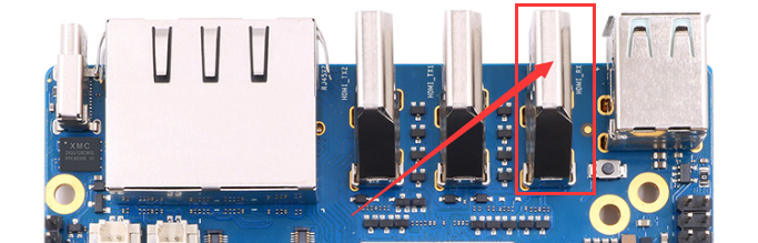
First use the HDMI to HDMI cable shown in the figure below to connect the HDMI output of other devices to the HDMI In interface of the development board
The HDMI In function of the Linux system is disabled by default, and the opening method is as follows:
First run orangepi-config, normal users remember to add sudo permission
orangepi@orangepi:~$ sudo orangepi-config
Then select System
Then select Hardware
Then use the arrow keys of the keyboard to navigate to the position shown in the figure below, and then use the space to select the hdmirx configuration

Then select <Save> to save
Then select <Back>
Then select <Reboot> to restart the system to make the configuration take effect
Restart the system and open a terminal on the desktop, then run the test_hdmiin.sh script
[orangepi@orangepi ~]$ test_hdmiin.sh
Then you can see the input screen of HDMI In (the HDMI In in the figure below shows the HDMI output screen of the opi5 development board, and a video is being played at this time). The test_hdmiin.sh script will play the audio input from HDMI In to HDMI_TX1, HDMI_TX2 and ES8388 (representing speakers or headphones) of the development board by default.
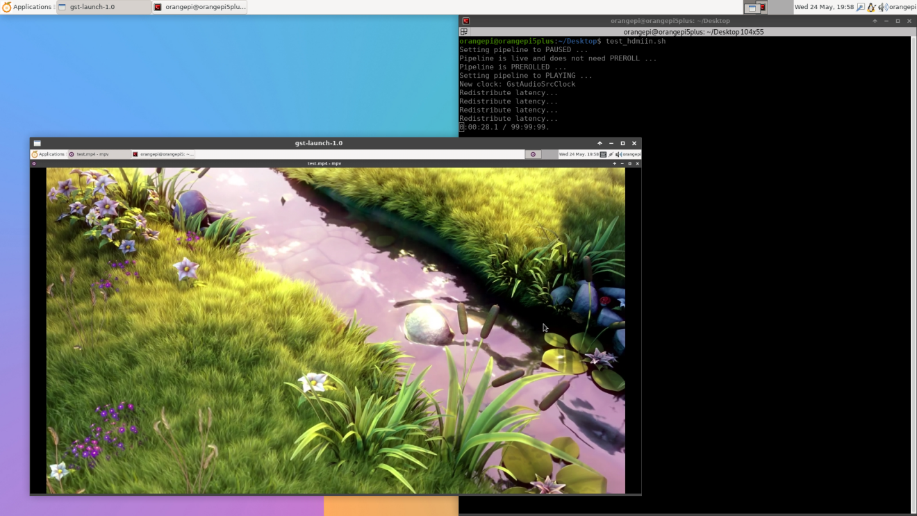


HDMI to VGA display test
First, you need to prepare the following accessories
HDMI to VGA Converter
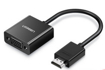
A VGA cable
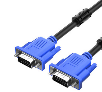
A monitor or TV that supports VGA interface
The HDMI to VGA display test is as follows:
When using HDMI to VGA display, the development board and the Linux system of the development board do not need to make any settings, only the HDMI interface of the development board can display normally. So if there is a problem with the test, please check whether there is a problem with the HDMI to VGA converter, VGA cable and monitor.


HDMI resolution setting method
First open Display in Settings

Then you can see the current resolution of the system
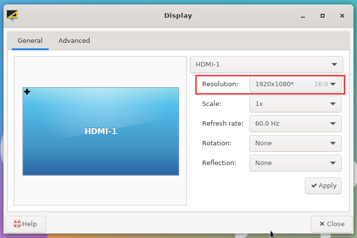
Click the drop-down box of Resolution to see all resolutions currently supported by the monitor
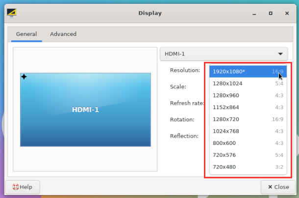
Then select the resolution you want to set, and click Apply
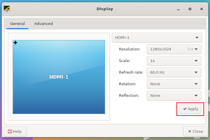
After the new resolution is set, select Keep the configuration


How to use Bluetooth
|
Please note that there is no Bluetooth module on the Orange Pi 5 Plus development board, and an external PCIe network card with Bluetooth or a USB network card with Bluetooth is required to use the Bluetooth function. For instructions on using the external PCIe network card, please refer to the section on how to use the PCIe WIFI6+Bluetooth module. For instructions on using the external USB network card, please refer to the USB wireless network card test section. |
Test method of desktop image
Click on the Bluetooth icon in the upper right corner of the desktop
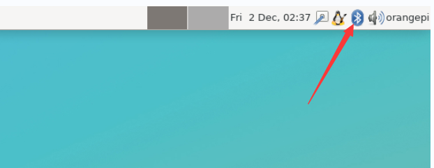
Then select the adapter
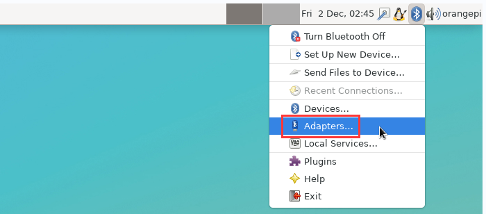
If there is a prompt on the following interface, please select Yes
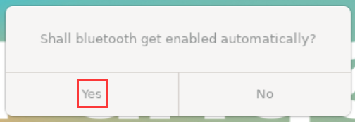
Then set the Visibility Setting to Always visible in the Bluetooth adapter setting interface, and then close it
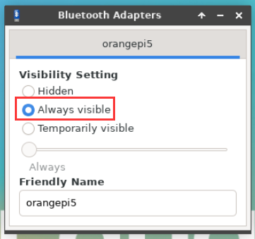
Then open the configuration interface of the Bluetooth device
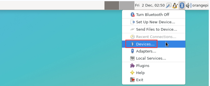
Click Search to start scanning the surrounding Bluetooth devices
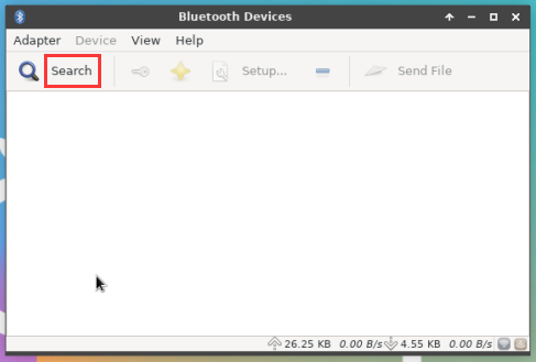


Then select the Bluetooth device you want to connect to, and then click the right mouse button to pop up the operation interface for this Bluetooth device, select Pair to start pairing, and the demonstration here is to pair with an Android phone

When pairing, a pairing confirmation box will pop up in the upper right corner of the desktop, just select Confirm to confirm, and the phone also needs to confirm at this time
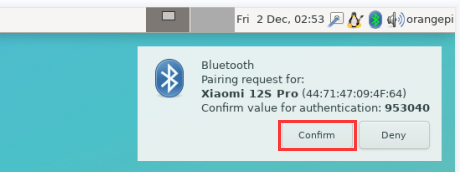
After pairing with the mobile phone, you can select the paired Bluetooth device, then right-click and select Send a File to start sending a picture to the mobile phone
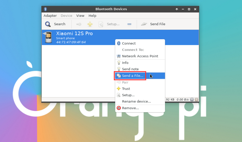
The interface for sending pictures is as follows
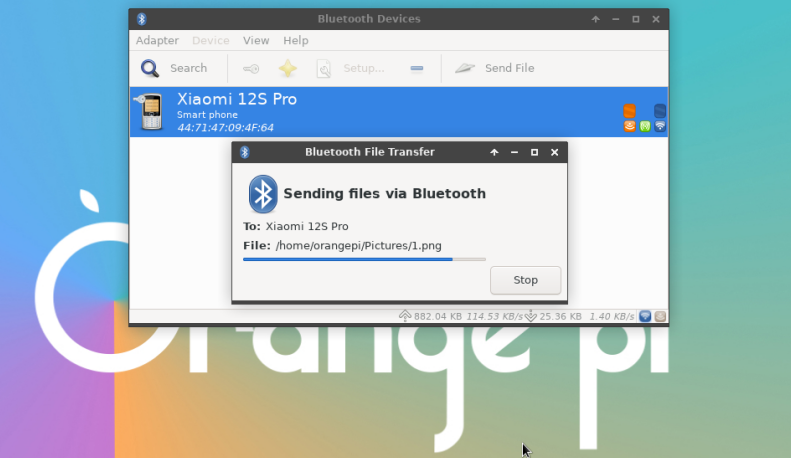


USB interface test
|
The USB interface can be connected to a USB hub to expand the number of USB interfaces. |
Connect USB mouse or keyboard to test
- Insert the keyboard with USB interface into the USB interface of Orange Pi development board
- Connect the Orange Pi development board to the HDMI display
- If the mouse or keyboard can operate normally, it means that the USB interface is working normally (the mouse can only be used in the desktop version of the system)
Connect USB storage device test
- First insert the U disk or USB mobile hard disk into the USB interface of the Orange Pi development board
- Execute the following command, if you can see the output of sdX, it means that the U disk is recognized successfully
orangepi@orangepi:~$ cat /proc/partitions | grep "sd*"
major minor #blocksname
8030044160 sda
8130043119 sda1
- Use the mount command to mount the U disk to /mnt, and then you can view the files in the U disk
|
orangepi@orangepi:~$ sudo mount /dev/sda1 /mnt/ orangepi@orangepi:~$ ls /mnt/ test.txt |
- After mounting, you can view the capacity usage and mount point of the U disk through the df -h command
|
orangepi@orangepi:~$ df -h | grep "sd" /dev/sda1 29G 208K 29G 1% /mnt |
USB wireless network card test
The usable USB wireless network cards that have been tested so far are as follows. For other types of USB wireless network cards, please test them yourself. If they cannot be used, you need to transplant the corresponding USB wireless network card driver.
| S/N | model | Physical picture |
| 1 | RTL8723BU
Support 2.4G WIFI+BT4.0 |

|
| 2 | RTL8811
Support 2.4G +5G WIFI |

|
| 3 | RTL8821CU
Support 2.4G +5G WIFI Support BitTorrent 4.2 |

|
RTL8723BU test
First insert the RTL8723BU wireless network card module into the USB interface of the development board
Then the linux system will automatically load the RTL8723BU bluetooth and WIFI-related kernel modules, through the lsmod command, you can see that the following kernel modules have been automatically loaded
orangepi@orangepi:~$ lsmod
Module Size Used by
rfcomm 5734416
rtl8xxxu 1064960
rtk_btusb 614400
Through the dmesg command, you can see the loading information of the RTL8723BU module
orangepi@orangepi:~$ dmesg
......
[ 83.438901] usb 2-1: new high-speed USB device number 2 using ehci-platform
[ 83.588375] usb 2-1: New USB device found, idVendor=0bda, idProduct=b720, bcdDevice= 2.00
[ 83.588403] usb 2-1: New USB device strings: Mfr=1, Product=2, SerialNumber=3
[ 83.588422] usb 2-1: Product: 802.11n WLAN Adapter
[ 83.588443] usb 2-1: Manufacturer: Realtek
[ 83.588460] usb 2-1: SerialNumber: 00e04c000001
[ 83.601974] Bluetooth: hci0: RTL: examining hci_ver=06 hci_rev=000b lmp_ver=06 lmp_subver=8723
[ 83.603894] Bluetooth: hci0: RTL: rom_version status=0 version=1
[ 83.603920] Bluetooth: hci0: RTL: loading rtl_bt/rtl8723b_fw.bin
[ 83.610108] Bluetooth: hci0: RTL: loading rtl_bt/rtl8723b_config.bin
[ 83.611274] Bluetooth: hci0: RTL: cfg_sz 68, total sz 22564
[ 83.658494] rtk_btusb: Realtek Bluetooth USB driver ver 3.1.6d45ddf.20220519-142432
[ 83.658651] usbcore: registered new interface driver rtk_btusb
[ 83.667124] usb 2-1: This Realtek USB WiFi dongle (0x0bda:0xb720) is untested!
[ 83.667137] usb 2-1: Please report results to Jes.Sorensen@gmail.com
[ 83.890140] usb 2-1: Vendor: Realtek
[ 83.890153] usb 2-1: Product: 802.11n WLAN Adapter
[ 83.890159] usb 2-1: rtl8723bu_parse_efuse: dumping efuse (0x200 bytes):
......
[ 83.890412] usb 2-1: RTL8723BU rev E (SMIC) 1T1R, TX queues 3, WiFi=1, BT=1, GPS=0, HI PA=0
[ 83.890417] usb 2-1: RTL8723BU MAC: 00:13:ef:f4:58:ae
[ 83.890421] usb 2-1: rtl8xxxu: Loading firmware rtlwifi/rtl8723bu_nic.bin
[ 83.895289] usb 2-1: Firmware revision 35.0 (signature 0x5301)
[ 84.050893] Bluetooth: hci0: RTL: fw version 0x0e2f9f73
[ 84.266905] Bluetooth: RFCOMM TTY layer initialized
[ 84.266949] Bluetooth: RFCOMM socket layer initialized
[ 84.266999] Bluetooth: RFCOMM ver 1.11
[ 84.884270] usbcore: registered new interface driver rtl8xxxu
[ 84.912046] rtl8xxxu 2-1:1.2 wlx0013eff458ae: renamed from wlan0
Then through the sudo ifconfig command, you can see the device node of RTL8723BU WIFI. For the connection and test method of WIFI, please refer to the section of WIFI connection test, which will not be repeated here
orangepi@orangepi:~$ sudo ifconfig wlx0013eff458ae
wlx0013eff458ae: flags=4099<UP,BROADCAST,MULTICAST> mtu 1500
ether 00:13:ef:f4:58:ae txqueuelen 1000 (Ethernet)
RX packets 0 bytes 0 (0.0 B)
RX errors 0 dropped 0 overruns 0 frame 0
TX packets 0 bytes 0 (0.0 B)
TX errors 0 dropped 0 overruns 0 carrier 0 collisions 0
Then you can see the USB Bluetooth device through the hciconfig command
orangepi@orangepi:~$ sudo apt update && sudo apt install bluez
orangepi@orangepi:~$ hciconfig
hci0: Type: Primary Bus: USB
BD Address: 00:13:EF:F4:58:AE ACL MTU: 820:8 SCO MTU: 255:16
DOWN
RX bytes:1252 acl:0 sco:0 events:125 errors:0
TX bytes:23307 acl:0 sco:0 commands:125 errors:0
You can also see the bluetooth icon on the desktop. At this time, the bluetooth is not turned on, so a red x will be displayed
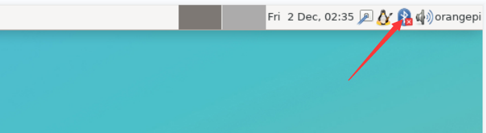
Click Turn Bluetooth On to turn on Bluetooth
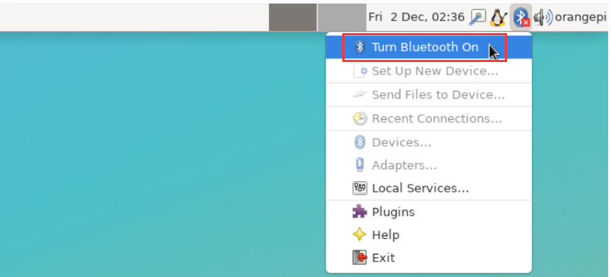
The display after turning on Bluetooth is as follows
For the test method of Bluetooth, please refer to the section on Bluetooth usage, so I won't go into details here


RTL8811 test
First insert the RTL8811 wireless network card module into the USB interface of the development board
Then the linux system will automatically load the kernel module related to RTL8811 WIFI, through the lsmod command, you can see that the following kernel module has been automatically loaded
orangepi@orangepi:~$ lsmod
Module Size Used by
8821cu 1839104 0
Through the dmesg command, you can see the loading information of the RTL8811 module
orangepi@orangepi:~$ dmesg
[ 118.618194] usb 2-1: new high-speed USB device number 2 using ehci-platform
[ 118.767152] usb 2-1: New USB device found, idVendor=0bda, idProduct=c811, bcdDevice= 2.00
[ 118.767181] usb 2-1: New USB device strings: Mfr=1, Product=2, SerialNumber=3
[ 118.767199] usb 2-1: Product: 802.11ac NIC
[ 118.767219] usb 2-1: Manufacturer: Realtek
[ 118.767235] usb 2-1: SerialNumber: 123456
[ 119.500530] usbcore: registered new interface driver rtl8821cu
[ 119.525498] rtl8821cu 2-1:1.0 wlx1cbfced9d260: renamed from wlan0
Then, you can see the WIFI device node through the sudo ifconfig command. For the WIFI connection and test method, please refer to the section of WIFI connection test, which will not be repeated here
orangepi@orangepi:~$ sudo ifconfig wlx1cbfced9d260
wlx1cbfced9d260: flags=4099<UP,BROADCAST,MULTICAST> mtu 1500
ether 1c:bf:ce:d9:d2:60 txqueuelen 1000 (Ethernet)
RX packets 0 bytes 0 (0.0 B)
RX errors 0 dropped 0 overruns 0 frame 0
TX packets 0 bytes 0 (0.0 B)
TX errors 0 dropped 0 overruns 0 carrier 0 collisions 0
USB camera test
First, you need to prepare a USB camera that supports the UVC protocol as shown in the figure below or similar, and then insert the USB camera into the USB port of the Orange Pi development board

Through the v4l2-ctl command, you can see that the device node information of the USB camera is /dev/video0
orangepi@orangepi:~$ v4l2-ctl --list-devices
Q8 HD Webcam: Q8 HD Webcam (usb-fc880000.usb-1):
/dev/video0
/dev/video1
/dev/media0
Note that the l in v4l2 is a lowercase letter l, not the number 1.
In addition, the serial number of the video is not necessarily video0, please refer to what you actually see.
In the desktop system, Cheese can be used to directly open the USB camera. The method of opening Cheese is shown in the figure below:
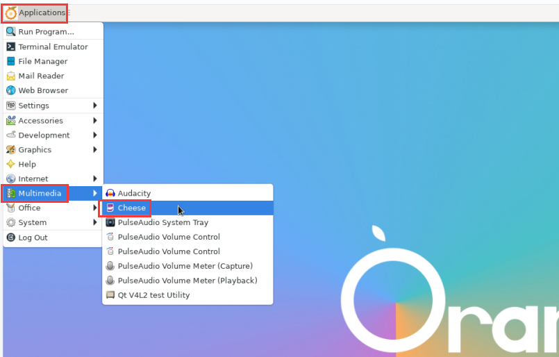
The interface after Cheese turns on the USB camera is shown in the figure below:
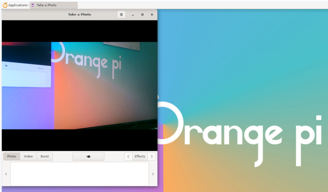
Method of using fswebcam to test USB camera
Install fswebcam
orangepi@orangepi:~$ sudo apt update
orangepi@orangepi:~$ sudo apt-get install -y fswebcam
After installing fswebcam, you can use the following command to take pictures
a) -d option is used to specify the device node of the USB camera
b) --no-banner is used to remove the watermark of the photo
c) -r option is used to specify the resolution of the photo
d) -S option is used to set the number of previous frames to skip
e) ./image.jpg is used to set the name and path of the generated photo
orangepi@orangepi:~$ sudo fswebcam -d /dev/video0 \
--no-banner -r 1280x720 -S 5 ./image.jpg
In the server version of the linux system, you can use the scp command to transfer the taken pictures to the Ubuntu PC for image viewing after taking pictures
orangepi@orangepi:~$ scp image.jpg test@192.168.1.55:/home/test (Modify the IP address and path according to the actual situation)
In the desktop version of the linux system, you can directly view the captured pictures through the HDMI display d. In the desktop version of the linux system, you can directly view the captured pictures through the HDMI display


Audio Test
Testing audio methods on desktop systems
First open the file manager
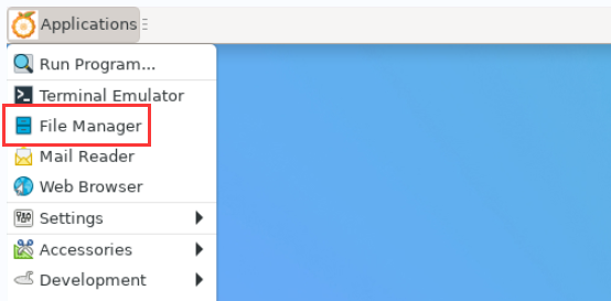
Then find the following file (if there is no audio file in the system, you can upload an audio file to the system yourself)
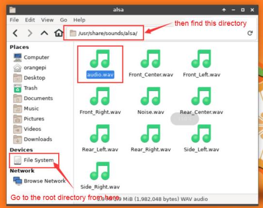
Then select the audio.wav file, right click and select open with vlc to start playing
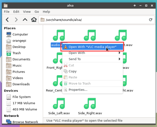
How to switch between different audio devices such as HDMI playback and headphone playback
First open the volume control interface
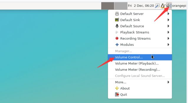
When playing audio, the audio device options that the playback software can use will be displayed in Playback, as shown in the figure below, where you can set which audio device to play to
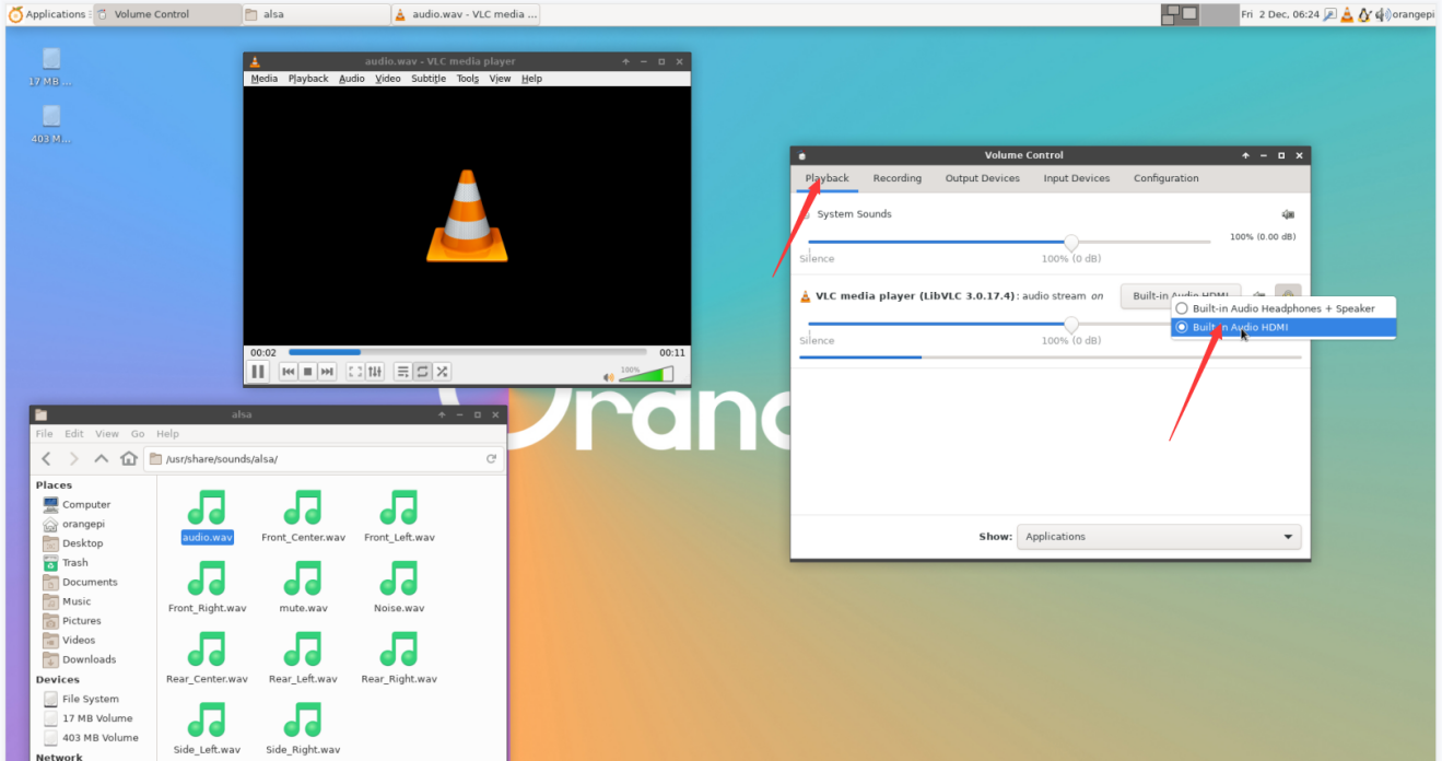


The method of using commands to play audio
Headphone interface playback audio test
First insert the earphone into the earphone jack of the development board
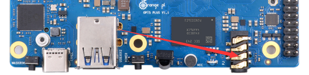
Then you can use the aplay -l command to view the sound card devices supported by the linux system. From the output below, you can see that card 3 is the sound card device of es8388, that is, the sound card device of the headset
orangepi@orangepi:~$ aplay -l
**** List of PLAYBACK Hardware Devices ****
card 0: rockchipdp0 [rockchip,dp0], device 0: rockchip,dp0 spdif-hifi-0 [rockchip,dp0 spdif-hifi-0]
Subdevices: 0/1
Subdevice #0: subdevice #0
card 1: rockchiphdmi0 [rockchip-hdmi0], device 0: rockchip-hdmi0 i2s-hifi-0 [rockchip-hdmi0 i2s-hifi-0]
Subdevices: 0/1
Subdevice #0: subdevice #0
card 2: rockchiphdmi1 [rockchip-hdmi1], device 0: rockchip-hdmi1 i2s-hifi-0 [rockchip-hdmi1 i2s-hifi-0]
Subdevices: 1/1
Subdevice #0: subdevice #0
card 3: rockchipes8388 [rockchip,es8388], device 0: dailink-multicodecs ES8323.7-0011-0 [dailink-multicodecs ES8323.7-0011-0]
Subdevices: 0/1
Subdevice #0: subdevice #0
Then use the aplay command to play the audio file that comes with the system. If the earphone can hear the sound, it means that the hardware can be used normally.
orangepi@orangepi:~$ aplay -D hw:3,0 /usr/share/sounds/alsa/audio.wav
Playing WAVE 'audio.wav' : Signed 16 bit Little Endian, Rate 44100 Hz, Stereo

Speaker interface playback audio test
First, you need to prepare a speaker as shown in the figure below. The specification of the speaker seat on the development board is 2pin 1.25mm pitch

The position of the speaker interface on the development board is as follows. After preparing the speaker, please insert it into the speaker interface of the development board
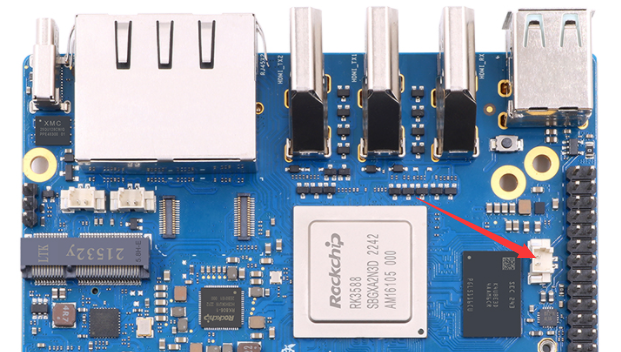
The speaker and earphone use the same sound card. Before using the speaker, please make sure that the earphone jack is not plugged into the earphone (if the earphone is plugged in, the audio will be played to the earphone). Then use the aplay command to play the audio file that comes with the system. If the speaker can hear the sound, it means that the hardware can be used normally.
orangepi@orangepi:~$ aplay -D hw:3,0 /usr/share/sounds/alsa/audio.wav
Playing WAVE 'audio.wav' : Signed 16 bit Little Endian, Rate 44100 Hz, Stereo

HDMI audio playback test
First use the HDMI to HDMI cable to connect the Orange Pi development board to the TV (other HDMI monitors need to ensure that they can play audio)
Then check the serial number of the HDMI sound card. From the output below, you can know that the sound card of HDMI_TX1 is card 1, and the sound card of HDMI_TX2 is card 2
orangepi@orangepi:~$ aplay -l
**** List of PLAYBACK Hardware Devices ****
card 0: rockchipdp0 [rockchip,dp0], device 0: rockchip,dp0 spdif-hifi-0 [rockchip,dp0 spdif-hifi-0]
Subdevices: 1/1
Subdevice #0: subdevice #0
card 1: rockchiphdmi0 [rockchip-hdmi0], device 0: rockchip-hdmi0 i2s-hifi-0 [rockchip-hdmi0 i2s-hifi-0]
Subdevices: 1/1
Subdevice #0: subdevice #0
card 2: rockchiphdmi1 [rockchip-hdmi1], device 0: rockchip-hdmi1 i2s-hifi-0 [rockchip-hdmi1 i2s-hifi-0]
Subdevices: 1/1
Subdevice #0: subdevice #0
Then use the aplay command to play the audio file that comes with the system. If the HDMI monitor or TV can hear the sound, it means that the hardware can be used normally.
The command to play audio to HDMI_TX1 is as follows:
orangepi@orangepi:~$ aplay -D hw:1,0 /usr/share/sounds/alsa/audio.wav
The command to play audio to HDMI_TX2 is as follows:
orangepi@orangepi:~$ aplay -D hw:2,0 /usr/share/sounds/alsa/audio.wav
Method of using commands to test recording
There is an onboard MIC on the development board, the location is as follows:
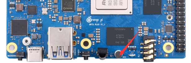
Running the test_record.sh main command will record a piece of audio through the onboard MIC, and then play it to HDMI_TX1 and the headset.
orangepi@orangepi:~$ test_record.sh main
Start recording: /tmp/test.wav
Recording WAVE '/tmp/test.wav' : Signed 16 bit Little Endian, Rate 44100 Hz, Stereo
Start playing
Playing WAVE '/tmp/test.wav' : Signed 16 bit Little Endian, Rate 44100 Hz, Stereo
Playing WAVE '/tmp/test.wav' : Signed 16 bit Little Endian, Rate 44100 Hz, Stereo
In addition to the onboard MIC, we can also record audio through headphones with MIC function. After inserting the headset with MIC function into the development board, run the test_record.sh headset command to record a piece of audio through the headset, and then play it to HDMI_TX1 and the headset.
orangepi@orangepi:~$ test_record.sh headset
Start recording: /tmp/test.wav
Recording WAVE '/tmp/test.wav' : Signed 16 bit Little Endian, Rate 44100 Hz, Stereo
Start playing
Playing WAVE '/tmp/test.wav' : Signed 16 bit Little Endian, Rate 44100 Hz, Stereo
Playing WAVE '/tmp/test.wav' : Signed 16 bit Little Endian, Rate 44100 Hz, Stereo

Temperature sensor
The command to view the system temperature sensor is:
|
orangepi@orangepi:~$ sensors gpu_thermal-virtual-0 Adapter: Virtual device temp1: +47.2°C
Adapter: Virtual device temp1: +47.2°C
Adapter: Virtual device temp1: +47.2°C
Adapter: rk3x-i2c in0: 0.00 V (min = +0.00 V, max = +0.00 V) curr1: 0.00 A (max = +0.00 A)
Adapter: Virtual device temp1: +47.2°C
Adapter: Virtual device temp1: +47.2°C
Adapter: Virtual device temp1: +47.2°C
Adapter: Virtual device temp1: +47.2°C (crit = +115.0°C) |
40 Pin Expansion Interface Pin Instructions

Please refer to the figure below for the order of the 40 pin expansion interface pins on the Orange Pi 5 Plus development board:
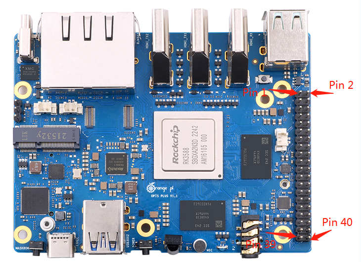
The functions of the 40 pin interface pins on the Orange Pi 5 Plus development board are shown in the table below
The following is the complete pin diagram of 40 pin
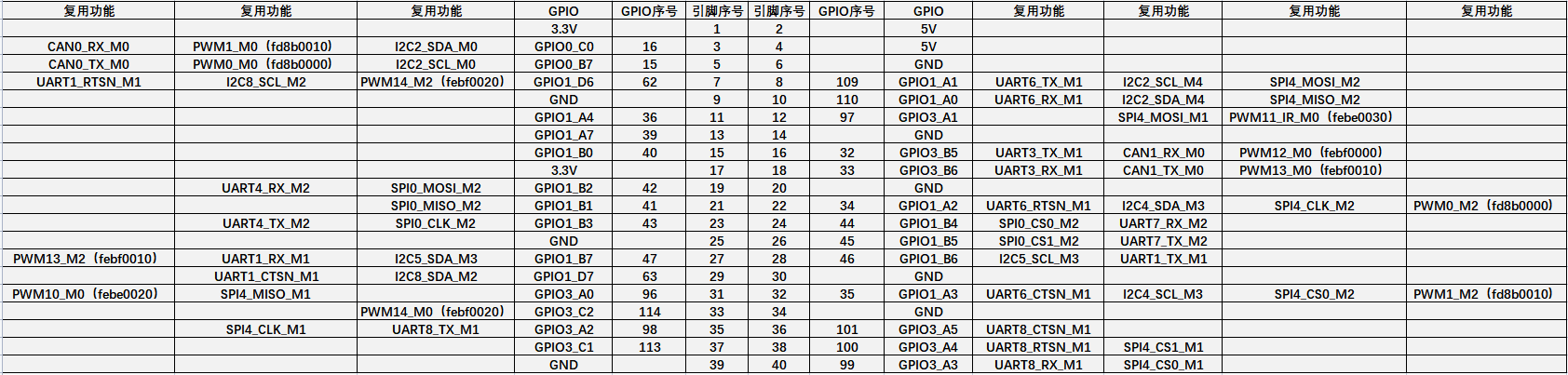
The following is a color map containing some of the content in the above table:
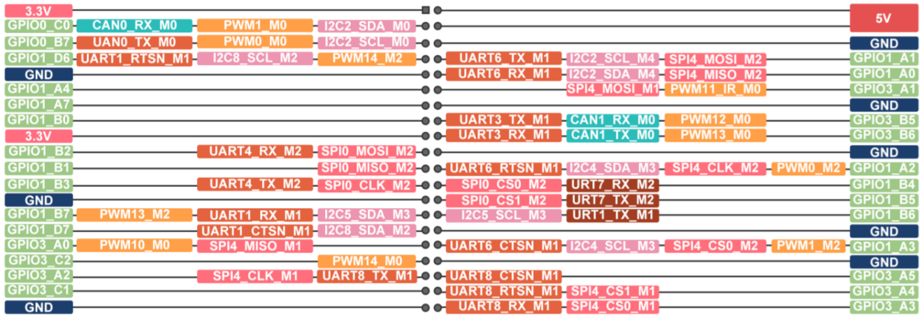
The table below is the picture of the left half of the complete > table above, so you can see it clearly
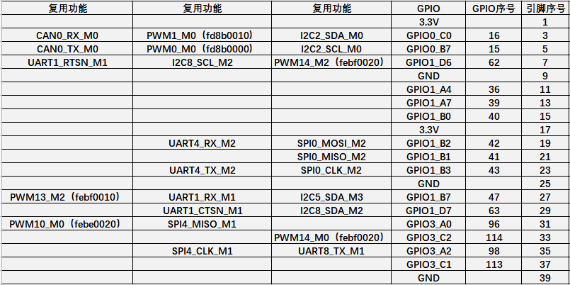
The table below is the picture of the right half of the complete > table above, so you can see it clearly
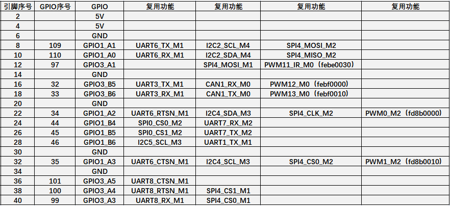
The pwm in the above table has marked the base address of the corresponding register, which is useful when checking which pwmchip in /sys/class/pwm/ corresponds to which pwm pin in the 40 pin header.
There are a total of 28 GPIO ports in the 40 pin interface, and the voltage of all GPIO ports is 3.3v.


How to install wiringOP
|
Note that wiringOP has been pre-installed in the linux image released by Orange Pi. Unless the code of wiringOP is updated, there is no need to re-download, compile and install, just use it directly. The storage path of the compiled wiringOP deb package in orangepi-build is: orangepi-build/external/cache/debs/arm64/wiringpi_x.xx.deb After entering the system, you can run the gpio readall command. If you can see the following output, it means that wiringOP has been pre-installed and can be used normally.
wiringOP is currently mainly adapted to the functions of setting GPIO port input and output, setting GPIO port output high and low levels, and setting up and down pull-down resistors. Functions such as hardware PWM are not available. |

Download the code of wiringOP
orangepi@orangepi:~$ sudo apt update
orangepi@orangepi:~$ sudo apt install -y git
orangepi@orangepi:~$ git clone https://github.com/orangepi-xunlong/wiringOP.git -b next
Note that Orange Pi 5 Plus needs to download the code of the wiringOP next branch, please don't miss the -b next parameter.
If you have problems downloading the code from GitHub, you can directly use the wiringOP source code that comes with the Linux image, and the storage location is: /usr/src/wiringOP
Compile and install wiringOP
orangepi@orangepi:~$ cd wiringOP
orangepi@orangepi:~/wiringOP$ sudo ./build clean
orangepi@orangepi:~/wiringOP$ sudo ./build
Test the output of the gpio readall command as follows
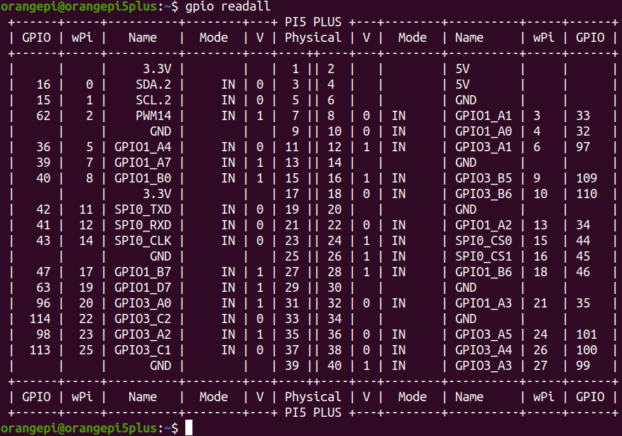
40 pin interface GPIO, I2C, UART, SPI, CAN and PWM test
40 pin GPIO port test
|
The linux system released by Orange Pi has a pre-installed blink_all_gpio program, which will set all 28 GPIO ports in the 40 pins to switch between high and low levels continuously. After running the blink_all_gpio program, when using a multimeter to measure the level of the GPIO port, you will find that the GPIO pin will switch between 0 and 3.3v continuously. Using this program we can test whether the GPIO port is working properly. The way to run the blink_all_gpio program is as follows: orangepi@orangepi5plus:~$ sudo blink_all_gpio #Remember to add sudo permission [sudo] password for orangepi: #A password is required here |
There are a total of 28 GPIO ports in the 40 pins of the development board that can be used. The following uses pin 7—the corresponding GPIO is GPIO1_D6——the corresponding wPi number is 2—as an example to demonstrate how to set the high and low levels of the GPIO port
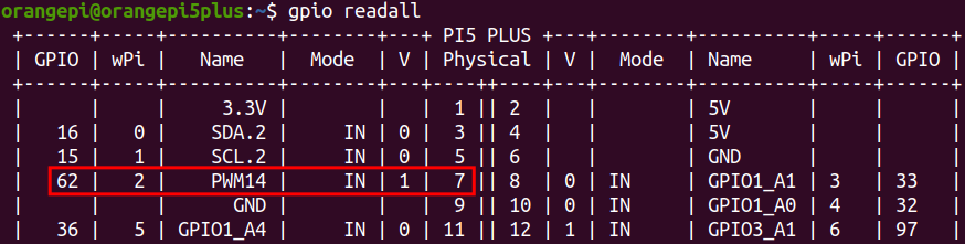
First set the GPIO port to output mode, where the third parameter needs to input the serial number of wPi corresponding to the pin
root@orangepi:~/wiringOP# gpio mode 2 out
Then set the GPIO port to output a low level. After setting, you can use a multimeter to measure the voltage value of the pin. If it is 0v, it means that the low level is set successfully.
root@orangepi:~/wiringOP# gpio write 2 0
Use gpio readall to see that the value (V) of pin 7 has changed to 0
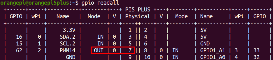
Then set the GPIO port to output a high level. After setting, you can use a multimeter to measure the voltage value of the pin. If it is 3.3v, it means that the high level is set successfully.
root@orangepi:~/wiringOP# gpio write 2 1
Use gpio readall to see that the value (V) of pin 7 has changed to 1
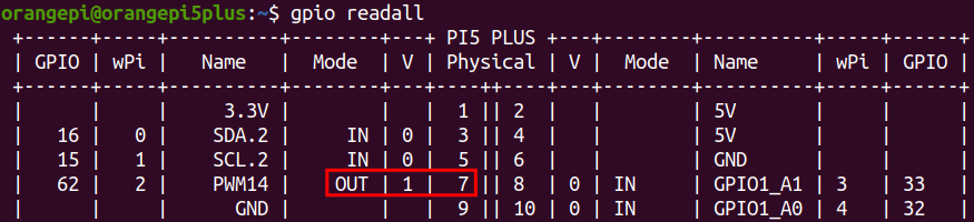
The setting method of other pins is similar, just modify the serial number of wPi to the corresponding serial number of the pin


How to set the pull-down resistance of pin GPIO port
The following takes pin No. 7—the corresponding GPIO is GPIO1_D6—the corresponding wPi number is 2—as an example to demonstrate how to set the pull-up and pull-down resistance of the GPIO port
First, you need to set the GPIO port to the input mode, and the third parameter needs to be the serial number of the wPi corresponding to the input pin
root@orangepi:~/wiringOP# gpio mode 2 in
After setting to input mode, execute the following command to set the GPIO port to pull-up mode
root@orangepi:~/wiringOP# gpio mode 2 up
Then enter the following command to read the level of the GPIO port, if the level is 1, it means that the pull-up mode is set successfully
root@orangepi:~/wiringOP# gpio read 2
1
Then execute the following command to set the GPIO port to pull-down mode
root@orangepi:~/wiringOP# gpio mode 2 down
Then enter the following command to read the level of the GPIO port, if the level is 0, the pull-down mode is set successfully
root@orangepi:~/wiringOP# gpio read 2
0
40 pin SPI test
As can be seen from the figure below, the SPIs available for Orange Pi 5 Plus are SPI0 and SPI4
The corresponding pins of SPI0 and SPI4 in 40pin are shown in the table below. SPI4_M1 and SPI4_M2 can only use one of them at the same time, and they cannot be used at the same time. They are all the same SPI4, but they are connected to different pins. Please don't think that they are two different sets of SPI buses.
| SPI0_M2 corresponds to 40pin | SPI4_M1 corresponds to 40pin | SPI4_M2 corresponds to 40pin | |
| MOSI | Pin 19 | Pin 12 | Pin 8 |
| MISO | Pin 21 | Pin 31 | Pin 10 |
| CLK | Pin 23 | Pin 35 | Pin 22 |
| CS0 | Pin 24 | Pin 40 | Pin 31 |
| CS1 | Pin 26 | Pin 38 | none |
| dtbo configuration | spi0-m2-cs0-spidev
spi0-m2-cs1-spidev spi0-m2 -cs0-cs1-spidev |
spi4-m1-cs0-spidev
spi4-m1-cs1-spidev spi4-m1 -cs0-cs1-spidev |
spi4-m2-cs0-spidev |
In the linux system, the SPI in the 40 pin is closed by default, and it needs to be opened manually before it can be used. The detailed steps are as follows:
First run orangepi-config, normal users remember to add sudo permission
orangepi@orangepi:~$ sudo orangepi-config
Then select System
Then select Hardware
Then use the arrow keys on the keyboard to navigate to the position shown in the figure below, and then use the space to select the SPI configuration you want to open
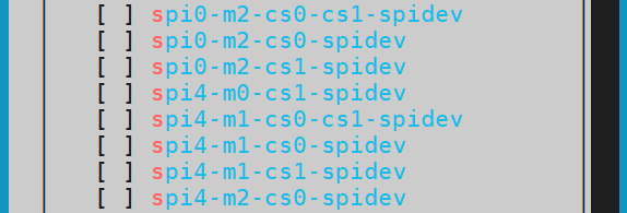
Then select <Save> to save
Then select <Back>
Then select <Reboot> to restart the system to make the configuration take effect
After restarting, enter the system and first check whether there is a spidevx.x device node in the linux system. If it exists, it means that the SPI has been set up and can be used directly.
orangepi@orangepi:~$ ls /dev/spidev*
/dev/spidev0.0 /dev/spidev0.1 /dev/spidev4.0 /dev/spidev4.1
The above is the result displayed after turning on spi0-m2-cs0-cs1-spidev and spi4-m1-cs0-cs1-spidev.
Then do not short-circuit the MOSI and MISO pins of SPI0 or SPI4, the output result of running spidev_test is as follows, you can see that the data of TX and RX are inconsistent
orangepi@orangepi:~$ sudo spidev_test -v -D /dev/spidev4.0
or
orangepi@orangepi:~$ sudo spidev_test -v -D /dev/spidev0.0
spi mode: 0x0
bits per word: 8
max speed: 500000 Hz (500 KHz)
TX | FF FF FF FF FF FF 40 00 00 00 00 95 FF FF FF FF FF FF FF FF FF FF FF FF FF FF FF FF FF FF F0 0D | ......@.…▒..................▒.
RX | FF FF FF FF FF FF FF FF FF FF FF FF FF FF FF FF FF FF FF FF FF FF FF FF FF FF FF FF FF FF FF FF | ............................….
Then short-circuit the MOSI and MISO pins of SPI0 or SPI4, and then run the output of spidev_test as follows. You can see that the sent and received data are the same, indicating that the SPI loopback test is normal.
orangepi@orangepi:~$ sudo spidev_test -v -D /dev/spidev4.0
or
orangepi@orangepi:~$ sudo spidev_test -v -D /dev/spidev0.0
spi mode: 0x0
bits per word: 8
max speed: 500000 Hz (500 KHz)
TX | FF FF FF FF FF FF 40 00 00 00 00 95 FF FF FF FF FF FF FF FF FF FF FF FF FF FF FF FF FF FF F0 0D | ......@.…▒..................▒.
RX | FF FF FF FF FF FF 40 00 00 00 00 95 FF FF FF FF FF FF FF FF FF FF FF FF FF FF FF FF FF FF F0 0D | ......@.…▒..................▒.

40 pin I2C test
As can be seen from the table below, the available i2c for Orange Pi 5 Plus is i2c2, i2c4, i2c5 and i2c8, a total of four sets of i2c buses.
The corresponding pins of the 4 groups of I2C buses in 40pin are shown in the table below. I2C2_M0 and I2C2_M4 can only use one of them at the same time, and they cannot be used at the same time. They are all the same I2C2, but they are connected to different pins. Please don’t think that they are two different sets of I2C2 buses.
| I2C bus | SDA corresponds to 40pin | SCL corresponds to 40pin | dtbo corresponding configuration |
| I2C2_M0 | Pin 3 | Pin 5 | i2c2-m0 |
| I2C2_M4 | Pin 10 | Pin 8 | i2c2-m4 |
| I2C4_M3 | Pin 22 | Pin 32 | i2c4-m3 |
| I2C5_M3 | Pin 27 | Pin 28 | i2c5-m3 |
| I2C8_M2 | Pin 29 | Pin 7 | i2c8-m2 |
In the linux system, the I2C bus in the 40 pin is closed by default, and it needs to be opened manually to use it. The detailed steps are as follows:
First run orangepi-config, normal users remember to add sudo permission
orangepi@orangepi:~$ sudo orangepi-config
Then select System
Then select Hardware
Then use the arrow keys on the keyboard to navigate to the position shown in the figure below, and then use the space to select the I2C configuration you want to open

Then select <Save> to save
Then select <Back>
Then select <Reboot> to restart the system to make the configuration take effect
After starting the linux system, first confirm that there are device nodes that need to use I2C under /dev
orangepi@orangepi:~$ ls /dev/i2c-*
Then connect an I2C device to the I2C pin corresponding to the 40 pin interface
Then use the i2cdetect -y command, if the address of the connected i2c device can be detected, it means that i2c can be used normally
orangepi@orangepi:~$ sudo i2cdetect -y 2 #i2c2 command
orangepi@orangepi:~$ sudo i2cdetect -y 4 #i2c4 command
orangepi@orangepi:~$ sudo i2cdetect -y 5 #i2c8 command
orangepi@orangepi:~$ sudo i2cdetect -y 8 #i2c8 command
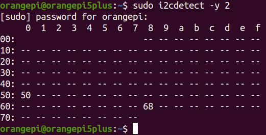


40 pin UART test
As can be seen from the table below, the uarts available for Orange Pi 5 Plus are uart1, uart3, uart4, uart6, uart7 and uart8, a total of 6 sets of uart buses
The corresponding pins of the 6 groups of UART buses in 40pin are shown in the following table:
| UART bus | RX corresponds to 40pin | TX corresponds to 40pin | dtbo corresponding configuration |
| UART1_M1 | Pin 27 | Pin 28 | uart1-m1 |
| UART3_M1 | Pin 18 | Pin 16 | uart3-m1 |
| UART4_M2 | Pin 19 | Pin 23 | uart4-m2 |
| UART6_M1 | Pin 10 | Pin 8 | uart6-m1 |
| UART7_M2 | Pin 24 | Pin 26 | uart7-m2 |
| UART8_M1 | Pin 40 | Pin 35 | uart8-m1 |
In the linux system, the UART in the 40 pin is closed by default, and it needs to be opened manually to use it. The detailed steps are as follows:
First run orangepi-config, normal users remember to add sudo permission
orangepi@orangepi:~$ sudo orangepi-config
Then select System
Then select Hardware
Then use the arrow keys on the keyboard to navigate to the position shown in the figure below, and then use the space to select the UART configuration you want to open

Then select <Save> to save
Then select <Back>
Then select <Reboot> to restart the system to make the configuration take effect
After entering the linux system, first confirm whether there is a device node corresponding to uart under /dev
orangepi@orangepi:~$ ls /dev/ttyS*
Then start to test the uart interface, first use the DuPont line to short the rx and tx pins of the uart interface to be tested
Use the gpio serial command to test the loopback function of the serial port as shown below. If you can see the following print, it means that the serial port communication is normal (ttySX needs to be replaced with the node name corresponding to uart, please do not copy it)
orangepi@orangepi:~$ sudo gpio serial /dev/ttySX
[sudo] password for orangepi: #enter password here
Out: 0: -> 0
Out: 1: -> 1
Out: 2: -> 2
Out: 3: -> 3
Out: 4: -> 4
Out: 5: -> 5^C

PWM test method
As can be seen from the table below, the available PWM for Orange Pi 5 Plus includes six channels of PWM: pwm0, pwm1, pwm11, pwm12, pwm13 and pwm14
The corresponding pins of PWM in 40pin are shown in the table below. Only one of PWM0_M0 and PWM0_M2, PWM1_M0 and PWM1_M2, PWM14_M0 and PWM14_M2 can be used at the same time, and they cannot be used at the same time. They are all the same PWM, but they are connected to different pins. Please don’t think that they are two different PWM bus.
| PWM总线 | Corresponding to 40pin | dtbo corresponding configuration |
| PWM0_M0 | Pin 5 | pwm0-m0 |
| PWM0_M2 | Pin 22 | pwm0-m2 |
| PWM1_M0 | Pin 3 | pwm1-m0 |
| PWM1_M2 | Pin 32 | pwm1-m2 |
| PWM11_M0 | Pin 12 | pwm11-m0 |
| PWM12_M0 | Pin 14 | pwm12-m0 |
| PWM13_M0 | Pin 16 | pwm13-m0 |
| PWM14_M0 | Pin 33 | pwm14-m0 |
| PWM14_M2 | Pin 7 | pwm14-m0 |
In the linux system, the PWM in the 40 pin is turned off by default, and it needs to be turned on manually before it can be used. The detailed steps are as follows:
First run orangepi-config, normal users remember to add sudo permission
orangepi@orangepi:~$ sudo orangepi-config
Then select System
Then select Hardware
Then use the arrow keys on the keyboard to navigate to the position shown in the figure below, and then use the space to select the PWM configuration you want to open
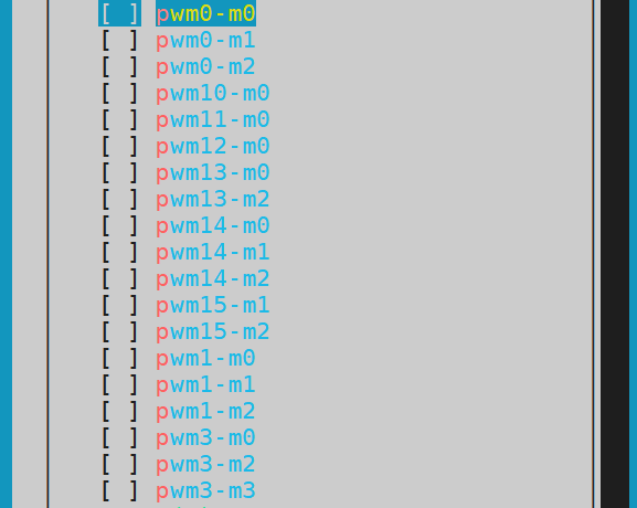
Then select <Save> to save
Then select <Back>
Then select <Reboot> to restart the system to make the configuration take effect
After opening a pwm, there will be an extra pwmchipX in /sys/class/pwm/ (X is a specific number), for example, after opening pwm14, check the pwmchipX under /sys/class/pwm/ two became three
orangepi@orangepi:~$ ls /sys/class/pwm/
pwmchip0 pwmchip1 pwmchip2
Which pwmchip above corresponds to pwm14? Let’s check the output of the ls /sys/class/pwm/ -l command first, as shown below:
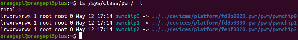
Then it can be known from the table below that the base address of the pwm14 register is febf0020, and then look at the output of the ls /sys/class/pwm/ -l command, you can see that pwmchip2 is linked to febf0020.pwm, so pwm14 corresponds to pwmchip as pwmchip2
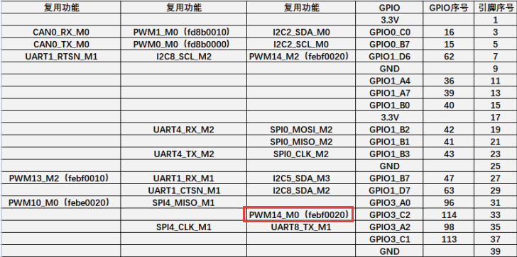
Then use the following command to make pwm14 output a 50Hz square wave (please switch to the root user first, and then execute the following command)


|
root@orangepi:~# echo 0 > /sys/class/pwm/pwmchip2/export root@orangepi:~# echo 20000000 > /sys/class/pwm/pwmchip2/pwm0/period root@orangepi:~# echo 1000000 > /sys/class/pwm/pwmchip2/pwm0/duty_cycle root@orangepi:~# echo 1 > /sys/class/pwm/pwmchip2/pwm0/enable
|
- The test method of pwm14 demonstrated above is similar to other pwm test methods.
CAN test method
How to open CAN
As can be seen from the table below, the available CAN bus for Orange Pi 5 Plus is CAN0 and CAN1, a total of two CAN buses
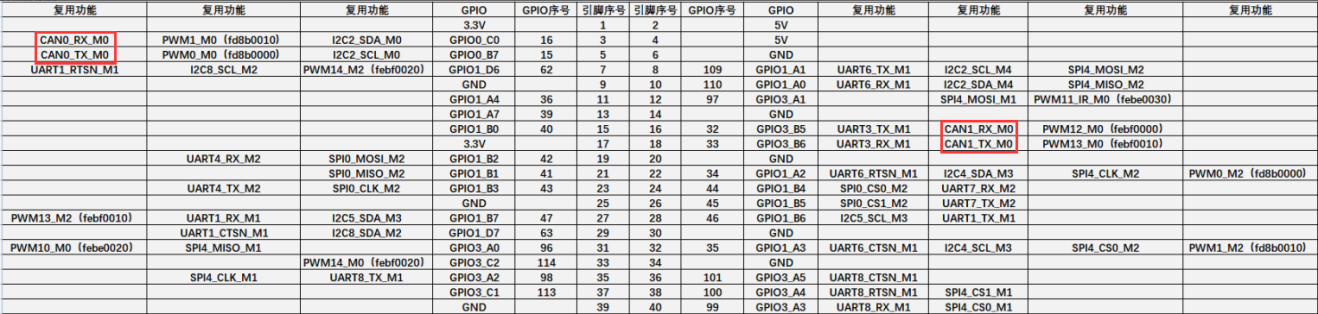
In the linux system, the CAN in the 40 pin is closed by default, and it needs to be opened manually before it can be used. The detailed steps are as follows:
First run orangepi-config, normal users remember to add > sudo permission
orangepi@orangepi:~$ sudo orangepi-config
Then select System
Then select Hardware
Then use the arrow keys on the keyboard to navigate to the > position shown in the figure below, and then use the space to > select the CAN configuration you want to open (can0-m0 and > cam1-m0 are optional for OPi 5 Plus)

Then select <Save> to save
Then select <Back>
Then select <Reboot> to restart the system to make the > configuration take effect
After entering the Linux system, use the sudo ifconfig -a command, if you can see the CAN device node, it means that the CAN has been opened correctly
orangepi@orangepi:~$ sudo ifconfig -a
can0: flags=128<NOARP> mtu 16
unspec 00-00-00-00-00-00-00-00-00-00-00-00-00-00-00-00 txqueuelen 10 (UNSPEC)
RX packets 0 bytes 0 (0.0 B)
RX errors 0 dropped 0 overruns 0 frame 0
TX packets 0 bytes 0 (0.0 B)
TX errors 0 dropped 0 overruns 0 carrier 0 collisions 0
device interrupt 94
can1: flags=128<NOARP> mtu 16
unspec 00-00-00-00-00-00-00-00-00-00-00-00-00-00-00-00 txqueuelen 10 (UNSPEC)
RX packets 0 bytes 0 (0.0 B)
RX errors 0 dropped 0 overruns 0 frame 0
TX packets 0 bytes 0 (0.0 B)
TX errors 0 dropped 0 overruns 0 carrier 0 collisions 0
device interrupt 95
The corresponding pins of CAN0 and CAN1 are


| CAN0 | CAN1 | |
| TX pin | Corresponding to pin 5 of 40pin | Corresponding to pin 18 of 40pin |
| RX pin | Corresponding to pin 3 of 40pin | Corresponding to pin 16 of 40pin |
Use the CANalyst-II analyzer to test sending and receiving messages
The CANalyst-II analyzer used in the test is shown in the figure below

CANalyst-II analyzer data download link
First install the software USBCANToolSetup
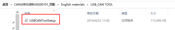
The shortcut after installation of USBCANToolSetup is

In addition, you need to install the USB driver
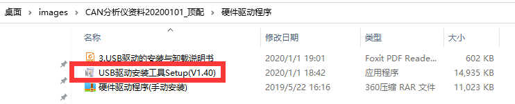
The end of the USB interface of the CANalyst-II analyzer needs to be connected to the USB interface of the computer
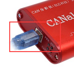
To test the CAN function, you need to prepare a CAN transceiver as shown in the figure below. The main function of the CAN transceiver is to convert the TTL signal of the CAN controller into the differential signal of the CAN bus
The 3.3V pin of the CAN transceiver needs to be connected to the 3.3V pin in the 40 pins of the development board
The GND pin of the CAN transceiver needs to be connected to the GND pin in the 40 pin of the development board
The CAN TX pin of the CAN transceiver needs to be connected to the TX pin of the CAN bus in the 40 pin of the development board
The CAN RX pin of the CAN transceiver needs to be connected to the RX pin of the CAN bus in the 40 pin of the development board
The CANL pin of the CAN transceiver needs to be connected to the H interface of the analyzer
The CANL pin of the CAN transceiver needs to be connected to the L interface of the analyzer

Then you can open the USB-CAN software
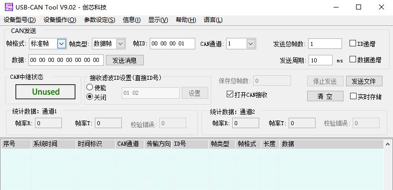
Then click to start the device
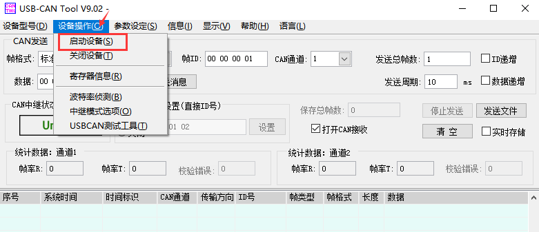
Then click OK
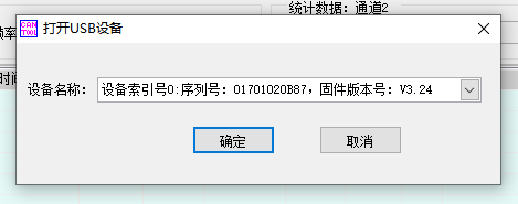
Set the baud rate to 1000k bps
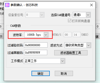
After successful opening, the USB-CAN software will display the serial number and other information
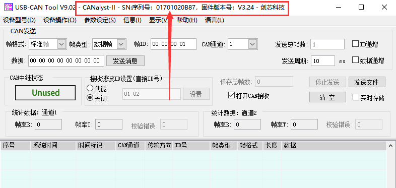
Development board receives CAN message test
a. First set the baud rate of the CAN bus to 1000kbps in the Linux system of the development board
orangepi@orangepi:~$ sudo ip link set can0 down
orangepi@orangepi:~$ sudo ip link set can0 type can bitrate 1000000
orangepi@orangepi:~$ sudo ip link set can0 up
Then run the candump can0 command to prepare to receive messages
orangepi@orangepi:~$ sudo candump can0
Then send a message to the development board in the USB-CAN software
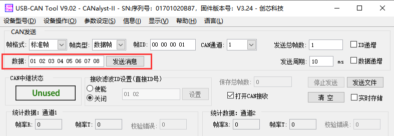
If the message sent by the analyzer can be received in the development board, it means that the CAN bus can be used normally
orangepi@orangepi5plus:~$ sudo candump can0
can0 001 [8] 01 02 03 04 05 06 07 08
Development board sends CAN message test
First set the CAN baud rate to 1000kbps in the Linux system
orangepi@orangepi:~$ sudo ip link set can0 down
orangepi@orangepi:~$ sudo ip link set can0 type can bitrate 1000000
orangepi@orangepi:~$ sudo ip link set can0 up
Execute the cansend command on the development board and send a message
orangepi@orangepi:~$ sudo cansend can0 123#1122334455667788
If the USB-CAN software can receive the message from the development board, the communication is successful
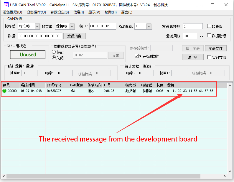


How to install and use wiringOP-Python
|
wiringOP-Python is the Python language version of wiringOP, which is used to operate the hardware resources of the development board, such as GPIO, I2C, SPI and UART, in the Python program. In addition, please note that all the following commands are operated under the root user. |
How to install wiringOP-Python
First install the dependency package
root@orangepi:~# sudo apt-get update
root@orangepi:~# sudo apt-get -y install git swig python3-dev python3-setuptools
Then use the following command to download the source code of wiringOP-Python
Note that the following git clone --recursive command will automatically download the source code of wiringOP, because wiringOP-Python depends on wiringOP. Please make sure that the download process does not report errors due to network problems.
If you have problems downloading the code from GitHub, you can directly use the wiringOP-Python source code that comes with the Linux image, and the storage location is: /usr/src/wiringOP-Python.
root@orangepi:~# git clone --recursive https://github.com/orangepi-xunlong/wiringOP-Python -b next
root@orangepi:~# cd wiringOP-Python
root@orangepi:~/wiringOP-Python# git submodule update --init --remote
Then use the following command to compile wiringOP-Python and install it into the Linux system of the development board
root@orangepi:~# cd wiringOP-Python
root@orangepi:~/wiringOP-Python# python3 generate-bindings.py > bindings.i
root@orangepi:~/wiringOP-Python# sudo python3 setup.py install
Then enter the following command, if there is help information output, it means that wiringOP-Python is installed successfully, press the q key to exit the help information interface
- wiringpi
- # This file was automatically generated by SWIG (http://www.swig.org).
- # Version 4.0.2
- #
- # Do not make changes to this file unless you know what you are doing--modify
- # the SWIG interface file instead.
|
root@orangepi:~/wiringOP-Python# python3 -c "import wiringpi; help(wiringpi)" Help on module wiringpi:
|
The steps to test whether wiringOP-Python is successfully installed under the python command line are as follows:
- First use the python3 command to enter the command line mode of python3
root@orangepi:~# python3
- Then import the python module of wiringpi
>>> import wiringpi;
- Finally, enter the following command to view the help information of wiringOP-Python, and press the q key to exit the help information interface
- wiringpi
- # This file was automatically generated by SWIG (http://www.swig.org).
- # Version 4.0.2
- #
- # Do not make changes to this file unless you know what you are doing--modify
- # the SWIG interface file instead.
- builtins.object
- GPIO
- I2C
- Serial
- nes
- class GPIO(builtins.object)
- | GPIO(pinmode=0)
- |
>>> help(wiringpi)
Help on module wiringpi:
NAME
DESCRIPTION
CLASSES
>>>
40 pin GPIO port test
|
wiringOP-Python is the same as wiringOP, you can also determine which GPIO pin to operate by specifying the wPi number, because there is no command to check the wPi number in wiringOP-Python, so you can only check the board wPi number and physical Correspondence between pins.
|
The following takes pin No. 7—the corresponding GPIO is GPIO1_D6—the corresponding wPi number is 2—as an example to demonstrate how to set the high and low levels of the GPIO port
The steps to test directly with the command are as follows:
First set the GPIO port to output mode, where the first > parameter of the pinMode function is the serial number of > the wPi corresponding to the pin, and the second parameter is > the GPIO mode
root@orangepi:~/wiringOP-Python# python3 -c "import wiringpi; \
from wiringpi import GPIO; wiringpi.wiringPiSetup() ; \
wiringpi.pinMode(2, GPIO.OUTPUT) ; "
Then set the GPIO port to output a low level. After setting, you > can use a multimeter to measure the voltage value of the pin. > If it is 0v, it means that the low level is set successfully.
root@orangepi:~/wiringOP-Python# python3 -c "import wiringpi; \
from wiringpi import GPIO; wiringpi.wiringPiSetup() ;\
wiringpi.digitalWrite(2, GPIO.LOW)"
Then set the GPIO port to output a high level. After setting, > you can use a multimeter to measure the voltage value of the > pin. If it is 3.3v, it means that the high level is set > successfully.
root@orangepi:~/wiringOP-Python# python3 -c "import wiringpi; \
from wiringpi import GPIO; wiringpi.wiringPiSetup() ;\
wiringpi.digitalWrite(2, GPIO.HIGH)"
The steps to test in the command line of python3 are as follows:
First use the python3 command to enter the command line mode of > python3
root@orangepi:~# python3
Then import the python module of wiringpi
>>> import wiringpi
>>> from wiringpi import GPIO
Then set the GPIO port to output mode, where the first parameter > of the pinMode function is the serial number of the wPi > corresponding to the pin, and the second parameter is the GPIO > mode
>>> wiringpi.wiringPiSetup()
0
>>> wiringpi.pinMode(2, GPIO.OUTPUT)
Then set the GPIO port to output low level. After setting, you > can use a multimeter to measure the voltage value of the pin. > If it is 0v, it means that the low level is set successfully.
>>> wiringpi.digitalWrite(2, GPIO.LOW)
Then set the GPIO port to output a high level. After setting, > you can use a multimeter to measure the voltage value of the > pin. If it is 3.3v, it means that the high level is set > successfully.
>>> wiringpi.digitalWrite(2, GPIO.HIGH)
The method of wiringOP-Python setting GPIO high and low levels in python code can refer to the blink.py test program in the examples below. The blink.py test program will set the voltage of all GPIO ports in the 40 pins of the development board to change continuously.
root@orangepi:~/wiringOP-Python# cd examples
root@orangepi:~/wiringOP-Python/examples# ls blink.py
blink.py
root@orangepi:~/wiringOP-Python/examples# python3 blink.py
40 pin SPI test
As can be seen from the figure below, the SPIs available for Orange Pi 5 Plus are SPI0 and SPI4
The corresponding pins of SPI0 and SPI4 in 40pin are shown in the table below. SPI4_M1 and SPI4_M2 can only use one of them at the same time, and they cannot be used at the same time. They are all the same SPI4, but they are connected to different pins. Please don't think that they are two different sets of SPI buses.
| SPI0_M2 corresponds to 40pin | SPI4_M1 corresponds to 40pin | SPI4_M2 corresponds to 40pin | |
| MOSI | Pin 19 | Pin 12 | Pin 8 |
| MISO | Pin 21 | Pin 31 | Pin 10 |
| CLK | Pin 23 | Pin 35 | Pin 22 |
| CS0 | Pin 24 | Pin 40 | Pin 31 |
| CS1 | Pin 26 | Pin 38 | none |
| dtbo configuration | spi0-m2-cs0-spidev
spi0-m2-cs1-spidev spi0-m2-cs0-cs1-spidev |
spi4-m1-cs0-spidev
spi4-m1-cs1-spidev spi4-m1-cs0-cs1-spidev |
spi4-m2-cs0-spidev |
In the linux system, the SPI in the 40 pin is closed by default, and it needs to be opened manually before it can be used. The detailed steps are as follows:
First run orangepi-config, normal users remember to add > sudo permission
orangepi@orangepi:~$ sudo orangepi-config
Then select System
Then select Hardware
Then use the arrow keys on the keyboard to navigate to the > position shown in the figure below, and then use the space to > select the SPI configuration you want to open
Then select <Save> to save
Then select <Back>
Then select <Reboot> to restart the system to make the > configuration take effect
After restarting, enter the system and first check whether there is a spidevx.x device node in the linux system. If it exists, it means that the SPI has been set up and can be used directly.
orangepi@orangepi:~$ ls /dev/spidev*
/dev/spidev0.0 /dev/spidev0.1 /dev/spidev4.0 /dev/spidev4.1
The above is the result displayed after turning on spi0-m2-cs0-cs1-spidev and spi4-m1-cs0-cs1-spidev.
Then you can use the spidev_test.py program in the examples to test the loopback function of the SPI. The spidev_test.py program needs to specify the following two parameters:
--channel: Specify the channel number of SPI
--port: specify the port number of SPI
Do not short-circuit the MOSI and MISO pins of the SPI, the output of running spidev_test.py is as follows, you can see that the data of TX and RX are inconsistent
The x after the --channel and --port parameters needs to be replaced with the channel number of the specific SPI and the port number of the SPI.
root@orangepi:~/wiringOP-Python# cd examples
root@orangepi:~/wiringOP-Python/examples# python3 spidev_test.py --channel x --port x
spi mode: 0x0
max speed: 500000 Hz (500 KHz)
Opening device /dev/spidev4.1
TX | FF FF FF FF FF FF 40 00 00 00 00 95 FF FF FF FF FF FF FF FF FF FF FF FF FF FF FF FF FF FF F0 0D |......@.......…|
RX | FF FF FF FF FF FF FF FF FF FF FF FF FF FF FF FF FF FF FF FF FF FF FF FF FF FF FF FF FF FF FF FF |.............….|
Then use the Dupont wire to short-circuit the MOSI and MISO pins of the SPI, and then run the output of spidev_test.py as follows, you can see that the data sent and received are the same, indicating that the SPI loopback test is normal
The x after the --channel and --port parameters needs to be replaced with the channel number of the specific SPI and the port number of the SPI.
root@orangepi:~/wiringOP-Python# cd examples
root@orangepi:~/wiringOP-Python/examples# python3 spidev_test.py --channel x --port x
spi mode: 0x0
max speed: 500000 Hz (500 KHz)
Opening device /dev/spidev4.1
TX | FF FF FF FF FF FF 40 00 00 00 00 95 FF FF FF FF FF FF FF FF FF FF FF FF FF FF FF FF FF FF F0 0D |......@.......…|
RX | FF FF FF FF FF FF 40 00 00 00 00 95 FF FF FF FF FF FF FF FF FF FF FF FF FF FF FF FF FF FF F0 0D |......@.......…|
40 pin I2C test
As can be seen from the table below, the available i2c for Orange Pi 5 Plus is i2c2, i2c4, i2c5 and i2c8, a total of four sets of i2c buses.
The corresponding pins of the 4 groups of I2C buses in 40pin are shown in the table below. I2C2_M0 and I2C2_M4 can only use one of them at the same time, and they cannot be used at the same time. They are all the same I2C2, but they are connected to different pins. Please don’t think that they are two different sets of I2C2 buses.
| I2C bus | SDA corresponds to 40pin | SCL corresponds to 40pin | dtbo corresponding configuration |
| I2C2_M0 | Pin 3 | Pin 5 | i2c2-m0 |
| I2C2_M4 | Pin 10 | Pin 8 | i2c2-m4 |
| I2C4_M3 | Pin 22 | Pin 32 | i2c4-m3 |
| I2C5_M3 | Pin 27 | Pin 28 | i2c5-m3 |
| I2C8_M2 | Pin 29 | Pin 7 | i2c8-m2 |
In the linux system, the I2C bus in the 40 pin is closed by default, and it needs to be opened manually before it can be used. The detailed steps are as follows:
First run orangepi-config, normal users remember to add > sudo permission
orangepi@orangepi:~$ sudo orangepi-config
Then select System
Then select Hardware
Then use the arrow keys on the keyboard to navigate to the > position shown in the figure below, and then use the space to > select the I2C configuration you want to open
Then select <Save> to save
Then select <Back>
Then select <Reboot> to restart the system to make the > configuration take effect
After starting the linux system, first confirm that there is a device node corresponding to i2c under /dev
orangepi@orangepi:~$ ls /dev/i2c-*
Then connect an i2c device to the i2c pin of the 40 pin connector, here we take the ds1307 RTC module as an example

Then use the i2cdetect -y command, if the address of the connected i2c device can be detected, it means that i2c can be recognized normally.
orangepi@orangepi:~$ sudo i2cdetect -y 2 #i2c2 command
orangepi@orangepi:~$ sudo i2cdetect -y 4 #i2c4 command
orangepi@orangepi:~$ sudo i2cdetect -y 5 #i2c5 command
orangepi@orangepi:~$ sudo i2cdetect -y 8 #i2c8 command
Then you can run the ds1307.py test program in the wiringOP-Python/examples file to read the time of RTC
/dev/i2c-x needs to be replaced with the serial number of the specific i2c device node.
root@orangepi:~/wiringOP-Python# cd examples
root@orangepi:~/wiringOP-Python/examples# python3 ds1307.py --device "/dev/i2c-x"
Thu 2023-01-05 14:57:55
Thu 2023-01-05 14:57:56
Thu 2023-01-05 14:57:57
^C
exit

40 pin UART test
As can be seen from the table below, the uarts available for Orange Pi 5 Plus are uart1, uart3, uart4, uart6, uart7 and uart8, a total of 6 sets of uart buses
The corresponding pins of the 6 groups of UART buses in 40pin are shown in the following table:
| UART bus | RX` corresponds to 40pin | TX corresponds to 40pin | dtbo corresponding configuration |
| UART1_M1 | Pin 27 | Pin 28 | uart1-m1 |
| UART3_M1 | Pin 18 | Pin 16 | uart3-m1 |
| UART4_M2 | Pin 19 | Pin 23 | uart4-m2 |
| UART6_M1 | Pin 10 | Pin 8 | uart6-m1 |
| UART7_M2 | Pin 24 | Pin 26 | uart7-m2 |
| UART8_M1 | Pin 40 | Pin 35 | uart8-m1 |
In the linux system, the UART in the 40 pins is closed by default, and it needs to be opened manually before it can be used. The detailed steps are as follows:
First run orangepi-config, normal users remember to add sudo permission
orangepi@orangepi:~$ sudo orangepi-config
Then select System
Then select Hardware
Then use the arrow keys on the keyboard to navigate to the position shown in the figure below, and then use the space to select the UART configuration you want to open
Then select <Save> to save
Then select <Back>
Then select <Reboot> to restart the system to make the configuration take effect
After entering the linux system, first confirm whether there is a device node corresponding to uart under /dev
orangepi@orangepi:~$ ls /dev/ttyS*
Then start to test the uart interface, first use the DuPont line to short the rx and tx pins of the uart interface to be tested
Then use the serialTest.py program in wiringOP-Python/examples to test the loopback function of the serial port. As shown below, if you can see the print below, it means the serial port communication is normal.
/dev/ttySX needs to be replaced with the serial number of the specific uart device node.
root@orangepi:~/wiringOP-Python/examples# python3 serialTest.py --device "/dev/ttySX"
Out: 0: -> 0
Out: 1: -> 1
Out: 2: -> 2
Out: 3: -> 3
Out: 4:^C
exit
Hardware watchdog test
The watchdog_test program is pre-installed in the linux system released by Orange Pi, which can be tested directly.
The method to run the watchdog_test program is as follows:
The second parameter 10 indicates the counting time of the watchdog. If the dog is not fed within this time, the system will restart
We can feed the dog by pressing any key on the keyboard (except ESC). After feeding the dog, the program will print a line of keep alive to indicate that the dog is fed successfully
orangepi@orangepi:~$ sudo watchdog_test 10
open success
options is 33152,identity is sunxi-wdt
put_usr return,if 0,success:0
The old reset time is: 16
return ENOTTY,if -1,success:0
return ENOTTY,if -1,success:0
put_user return,if 0,success:0
put_usr return,if 0,success:0
keep alive
keep alive
keep alive
Check the serial number of RK3588 chip
The command to view the serial number of the RK3588 chip is as follows. The serial number of each chip is different, so the serial number can be used to distinguish multiple development boards.
|
orangepi@orangepi:~$ cat_serial.sh Serial : 1404a7682e86830c |
How to install Docker
The linux image provided by Orange Pi has pre-installed Docker, but the Docker service is not enabled by default
Use the enable_docker.sh script to enable the docker service, and then you can start using the docker command, and the docker service will be automatically started when the system is started next time
orangepi@orangepi:~$ enable_docker.sh
Then you can use the following command to test docker, if you can run hello-world, it means that docker can be used normally
orangepi@orangepi:~$ docker run hello-world
Unable to find image 'hello-world:latest' locally
latest: Pulling from library/hello-world
256ab8fe8778: Pull complete
Digest: sha256:7f0a9f93b4aa3022c3a4c147a449ef11e0941a1fd0bf4a8e6c9408b2600777c5
Status: Downloaded newer image for hello-world:latest
Hello from Docker!
This message shows that your installation appears to be working correctly.
.….
How to download and install arm64 version balenaEtcher
The download address of balenaEtcher arm64 version is:
The download address of the a.deb installation package is as follows, it needs to be installed before it can be used
The download address of the AppImage version that does not need to be installed is as follows: b. The download address of the AppImage version that does not need to be installed is as follows:
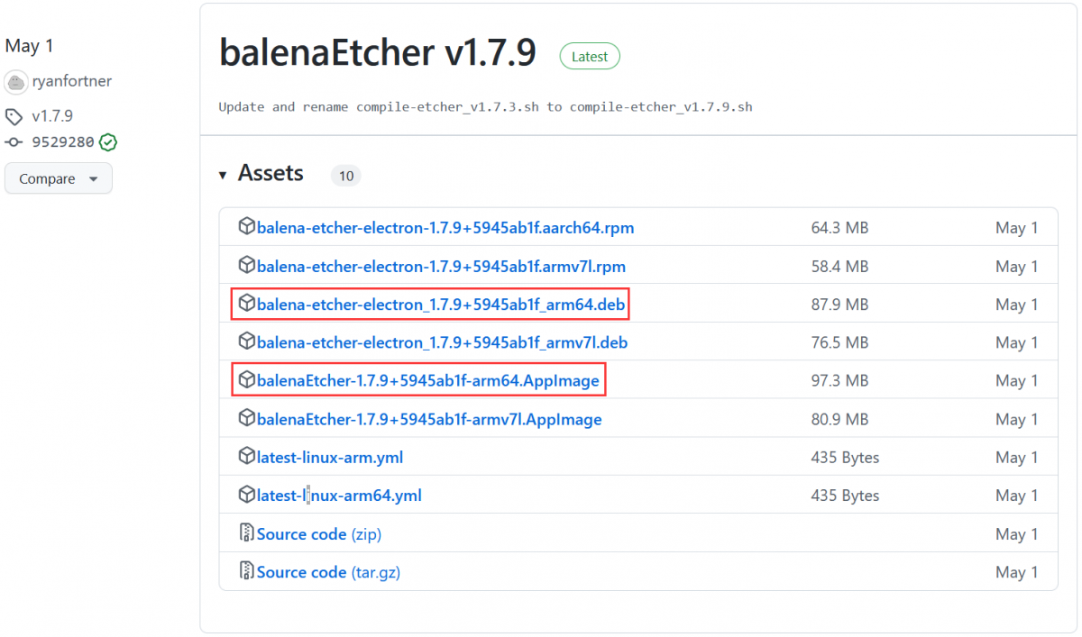

How to install and use deb version balenaEtcher:
The deb version of balenaEtcher installation command is as follows:
orangepi@orangepi:~$ sudo apt install -y \
--fix-broken ./balena-etcher-electron_1.7.9+5945ab1f_arm64.deb
After the deb version of balenaEtcher is installed, it can be opened in the Application

The interface after balenaEtcher is opened is as follows:
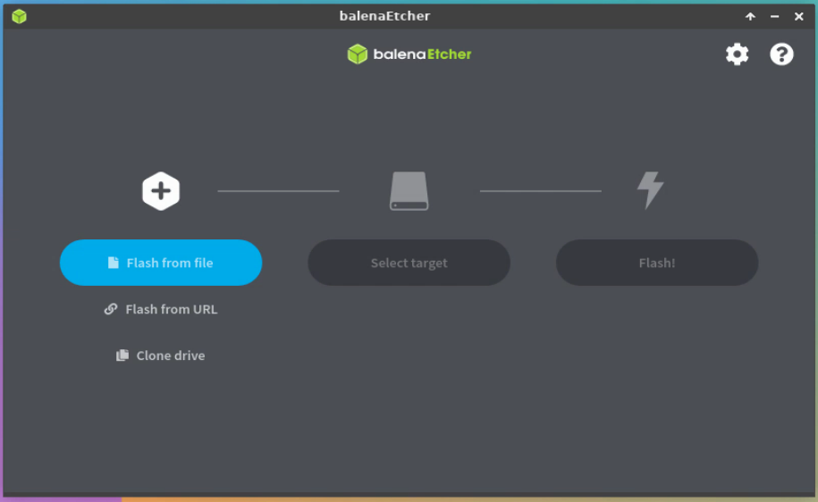

How to use the AppImage version of balenaEtcher:
First add permissions to balenaEtcher
orangepi@orangepi:~/Desktop$ chmod +x balenaEtcher-1.7.9+5945ab1f-arm64.AppImage
Then select the AppImage version balenaEtcher, click the right mouse button, and then click Execute to open balenaEtcher
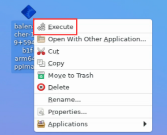

The installation method of the pagoda linux panel
|
Pagoda Linux panel is a server management software that improves operation and maintenance efficiency. It supports more than 100 server management functions such as one -click LAMP/LNMP/cluster/monitoring/website/FTP/database/Java (extracted from the official website of the pagoda) |
The order of compatibility recommendation of the pagoda Linux system is
Debian11 > Ubuntu 22.04 > Debian12
Then enter the following command in the Linux system to start the installation of the pagoda
orangepi@orangepi:~$ sudo install_bt_panel.sh
Then the pagoda installation program reminds whether to install the BT-Panel to the /www folder, and enter Y at this time
+----------------------------------------------------------------------
| Bt-WebPanel FOR CentOS/Ubuntu/Debian
+----------------------------------------------------------------------
| Copyright © 2015-2099 BT-SOFT(http://www.bt.cn) All rights reserved.
+----------------------------------------------------------------------
| The WebPanel URL will be http://SERVER_IP:8888 when installed.
+----------------------------------------------------------------------
Do you want to install Bt-Panel to the /www directory now?(y/n): y
Then what to do is to wait patiently. When you see the printing information below the terminal output, it means that the pagoda has been installed. The entire installation process takes about 9 minutes. There may be some differences according to the difference in network speed
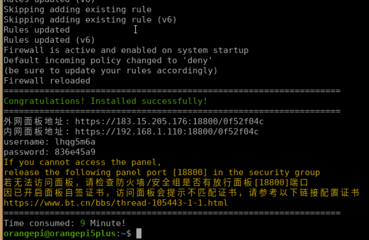
At this time, enter the panel address displayed above in the browser to open the login interface of the pagoda Linux panel, and then enter the username and password displayed above in the corresponding position to log in to the pagoda.
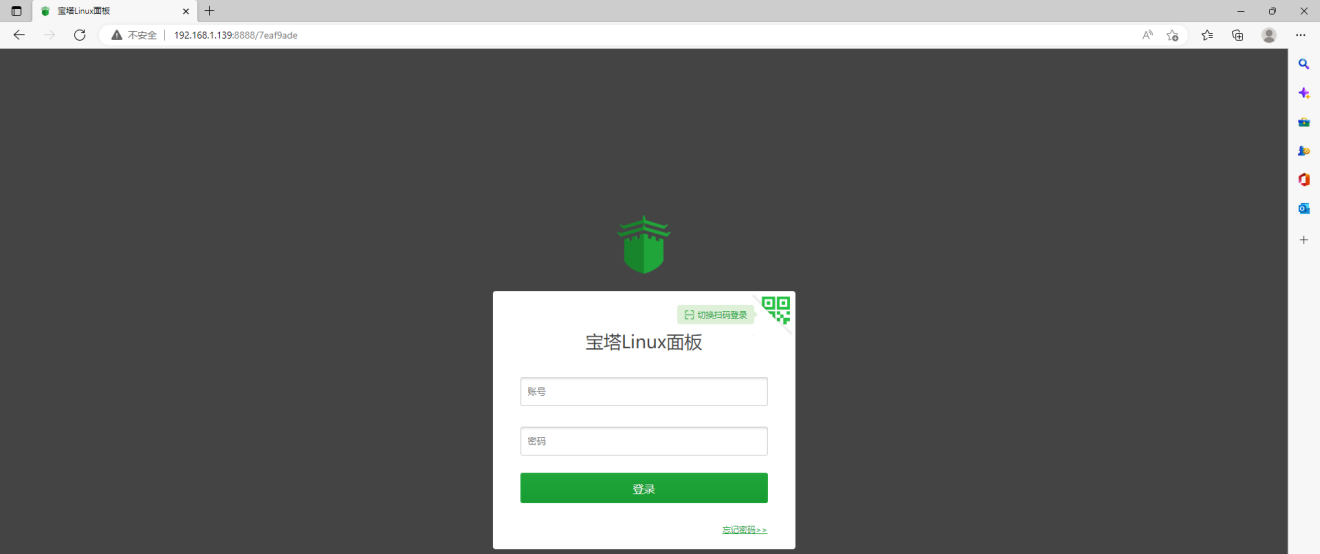
After successfully logging in to the pagoda, the following welcome interface will pop up. First, please take the intermediate user notice to read to the bottom, and then you can choose "I have agreed and read" User Agreement ", and then click" Enter the panel " You can enter the pagoda
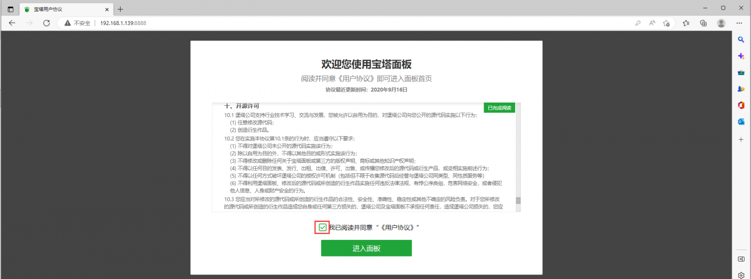
After entering the pagoda, you will first prompt that you need to bind the account of the pagoda official website. If you do n’t have an account, you can go to the official website of the pagoda (https://www.bt.cn) to register one
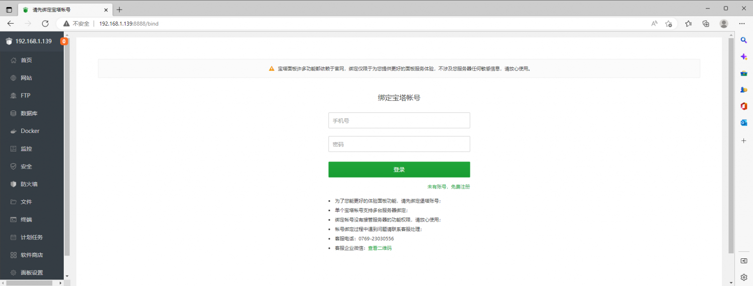
The final display interface is shown in the figure below. You can intuitively see some status information of the development board Linux system, such as load status, CPU usage, memory usage, and storage space usage
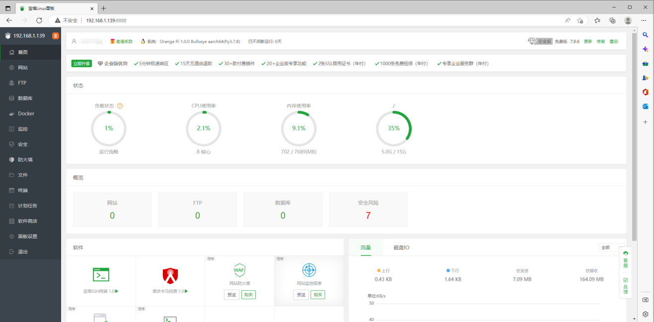
Test the SSH terminal login of the pagoda
After opening the SSH terminal of the pagoda, you will first prompt that you need to enter the password of the development board system. At this time, enter orangepi in the password box (the default password, if you have modification, please fill in the modified one).
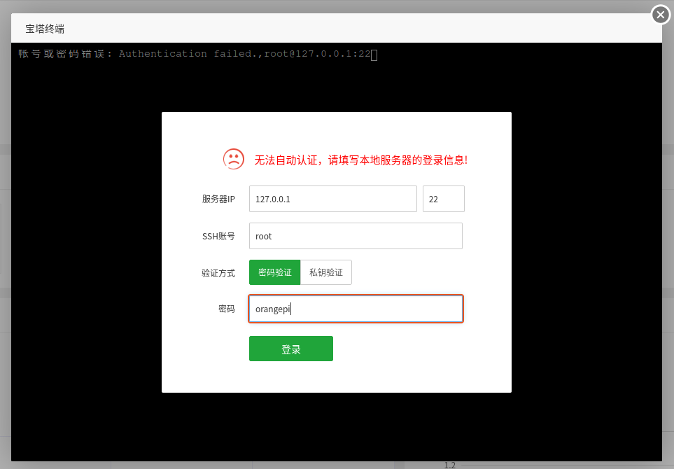
The display after successful login is shown in the figure below
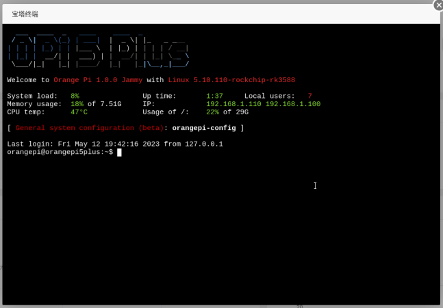
Software such as Apache, MySQL, and PHP can be installed in the software store of the pagoda. You can also deploy various applications in one click. Please explore it yourself
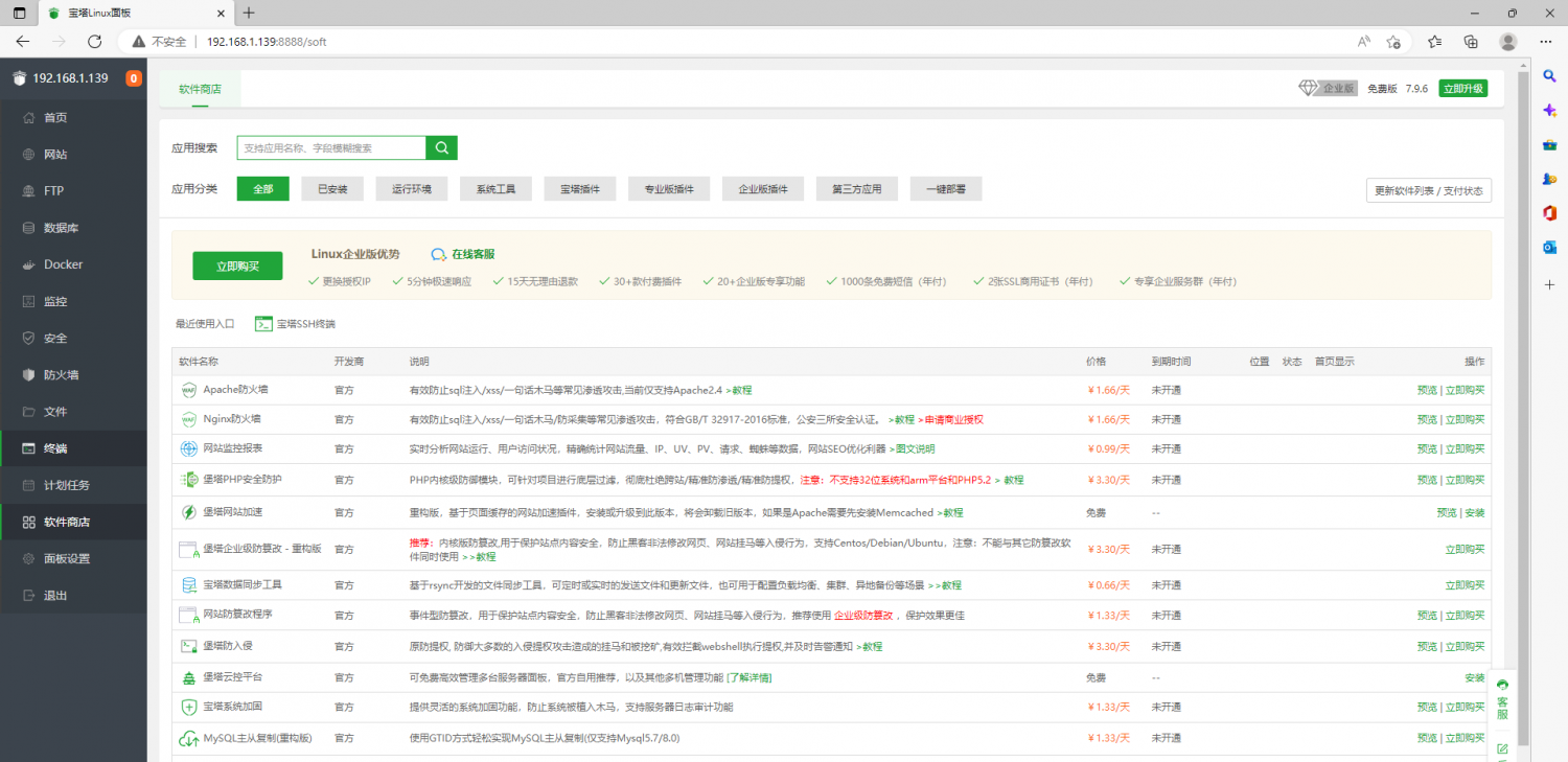
Pagoda command line tool test
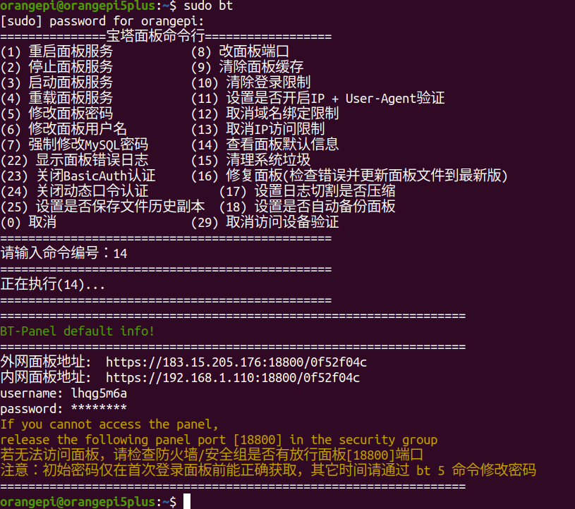
For more functions of the pagoda, please refer to the following information to explore by yourself
manual:http://docs.bt.cn
Forum address:https://www.bt.cn/bbs
GitHub Link:https://github.com/aaPanel/BaoTa


Set the Chinese environment and install Chinese input method
|
Note that before installing the Chinese input method, please make sure that the Linux system used in the development board is the desktop version system. |
Debian 11 system installation method
First set the default locale as Chinese
Enter the command below to start configured locale
orangepi@orangepi:~$ sudo dpkg-reconfigure locales
Then select zh_CN.UTF-8 UTF-8 in the pop-up interface (through the upper and lower direction keys on the keyboard to move up and down, select it through the space key, and finally move the cursor to <OK> through the Tab key, and then press Enter key.)
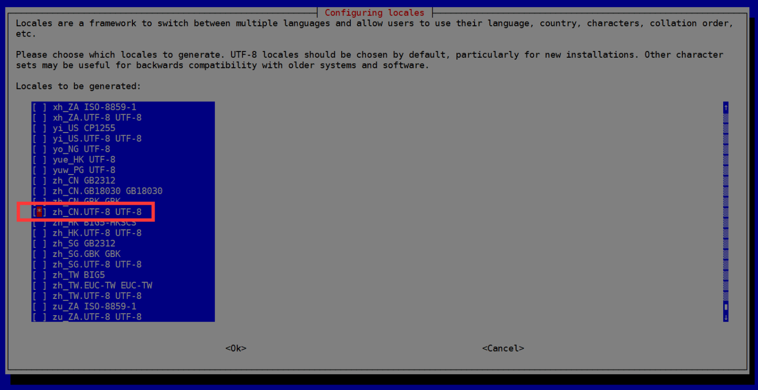
Then set the default locale as zh_CN.UTF-8
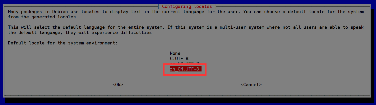
After exiting the interface,locale will be set. The output displayed by the command line is shown below
orangepi@orangepi:~$ sudo dpkg-reconfigure locales
Generating locales (this might take a while)...
en_US.UTF-8... done
zh_CN.UTF-8... done
Generation complete.
Then open Input Method

Then choose OK
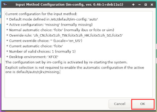
Then choose Yes
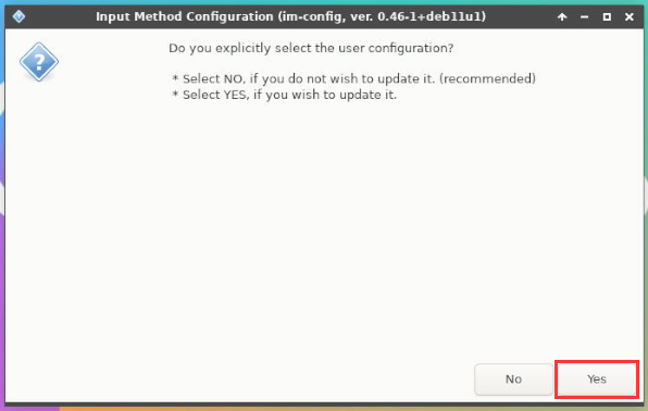
Then choose fcitx
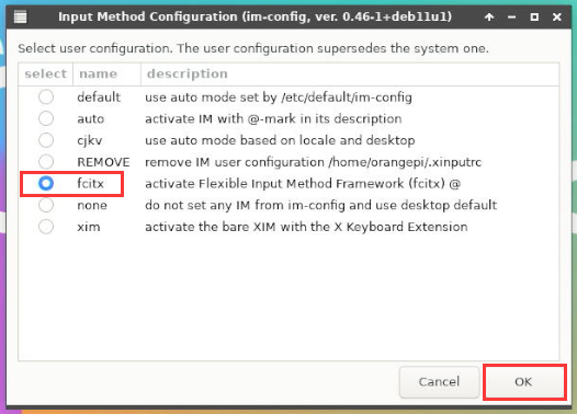
Then choose OK
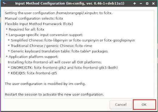
Then restart the Linux system to make the configuration effective
Then Open Fcitx configuration

Then click the “+” of the position shown in the figure below
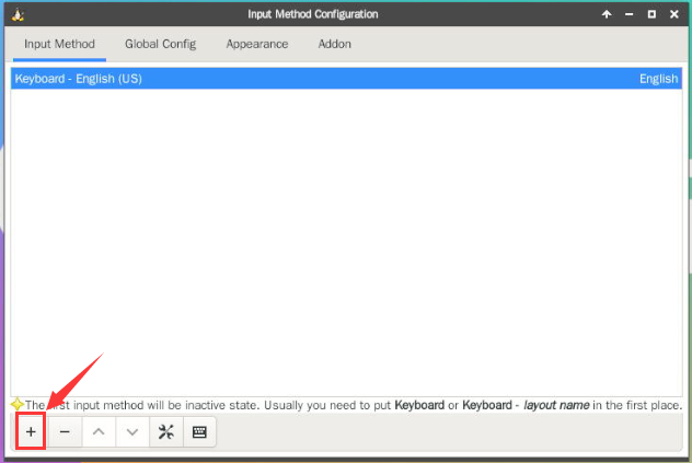
Then search Google Pinyin and click OK
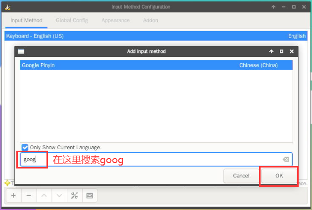
Then put Google Pinyin to the forefront
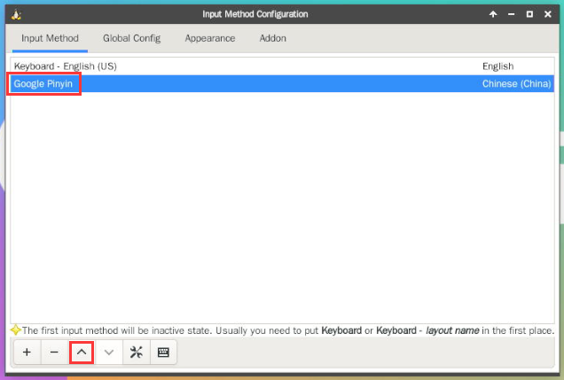
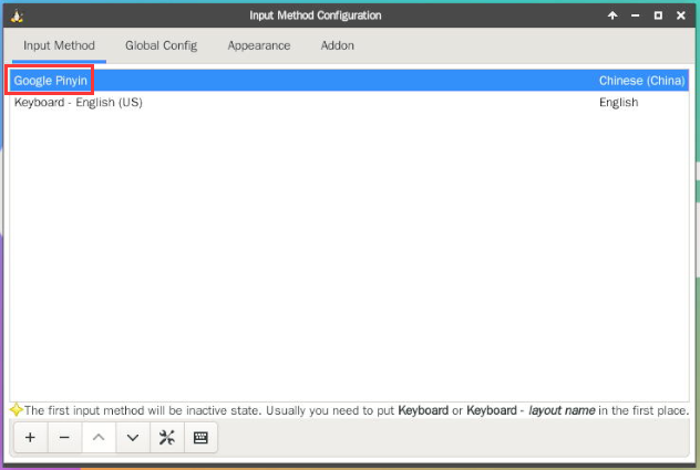
Then open the Geany Editor and test the Chinese input method.
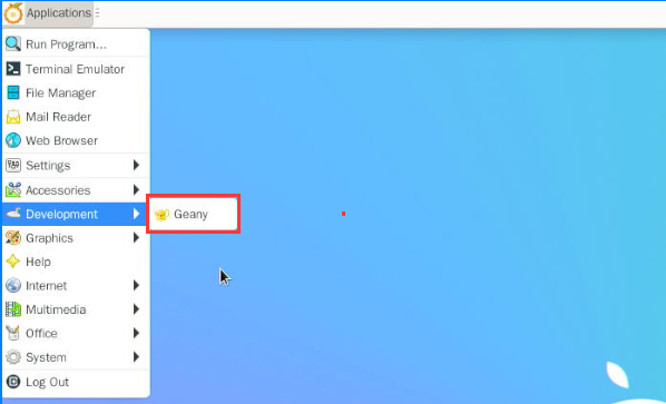
Chinese input method test is shown below
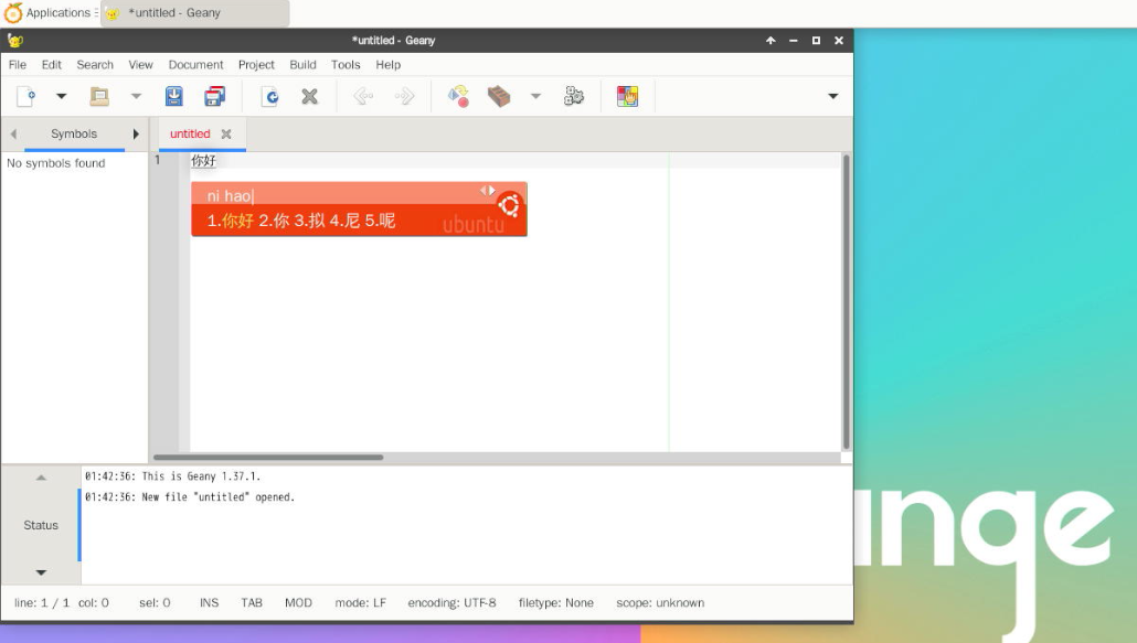
You can switch between Chinese and English input methods through Ctrl+Space shortcut
If the entire system is required as Chinese, the variables in /etc/default/locale can be set to zh_CN.UTF-8
orangepi@orangepi:~$ sudo vim /etc/default/locale
# File generated by update-locale
LC_MESSAGES=zh_CN.UTF-8
LANG=zh_CN.UTF-8
LANGUAGE=zh_CN.UTF-8
Then restart the system to see the system display as Chinese


ubuntu 20.04 system installation method
First open Language Support

Then find the Chinese (China) option
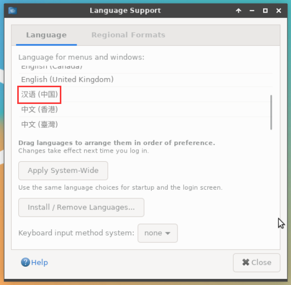
Then use the left mouse button to select Chinese (China) and hold it down, and then drag it up to the beginning. The display after dragging is shown in the figure below:
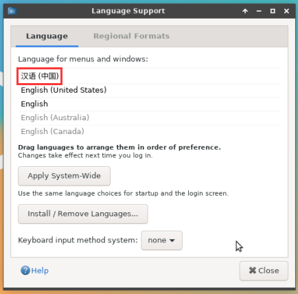


|
Note that this step is not very easy to drag, please try a few more times. |
Then select the Apply System-Wide to apply the Chinese settings to the entire system
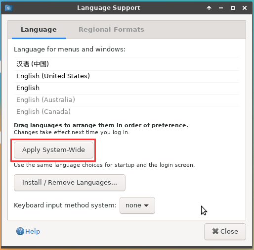
Then set the Keyboard input method system as fcitx
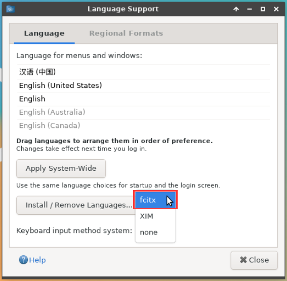
Then restart the linux system to make the configuration effective
After re -entering the system, please choose not to ask me again at the interface below, and then determine whether the standard folder should be updated in Chinese according to your preference
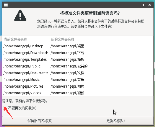
Then you can see that the desktop is displayed as Chinese

Then we can open the Geany test in the Chinese input method. The way to open the way is shown in the figure below

After opening Geany, the default is an English input method. We can switch into Chinese input method through the Ctrl+Space shortcut keys, and then we can enter Chinese
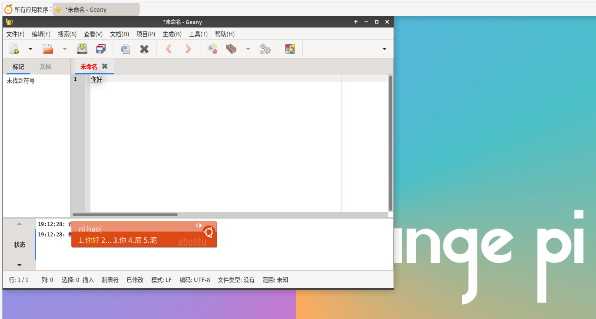


Ubuntu 22.04 installation method
First open Language Support
Then find the Chinese (China) option
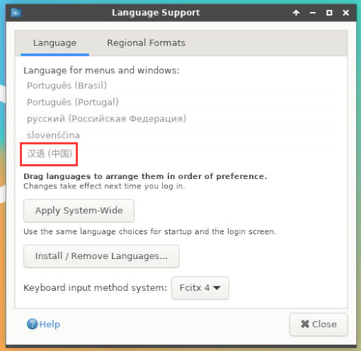
Then please use the mouse to select Chinese (China) and hold it down, and then drag it up to the beginning. The display after the dragging is shown in the figure below:
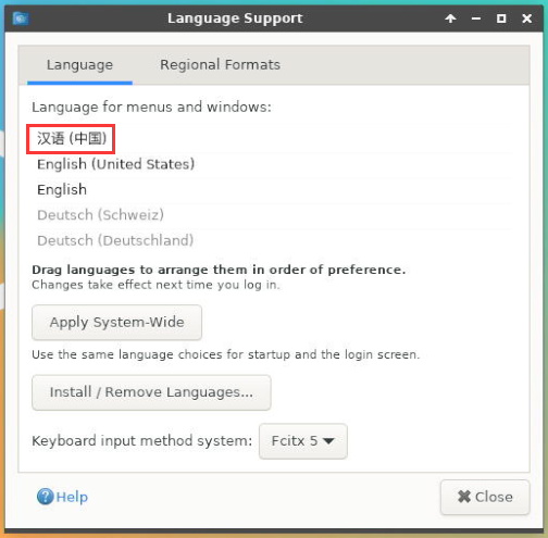


|
Note that this step is not very easy to drag, please try a few more times. |
Then select the Apply System-Wide to apply the Chinese settings to the entire system
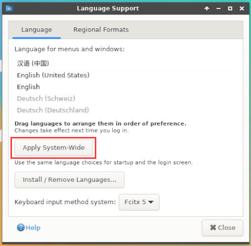
Then restart the linux system to make the configuration effective
After re-entering the system, please choose not to ask me again at the interface below, and then determine whether the standard folder should be updated to Chinese according to your preference
Then you can see that the desktop is displayed as Chinese
Then open the Fcitx5 configuration program

Then choose to use Pinyin input method
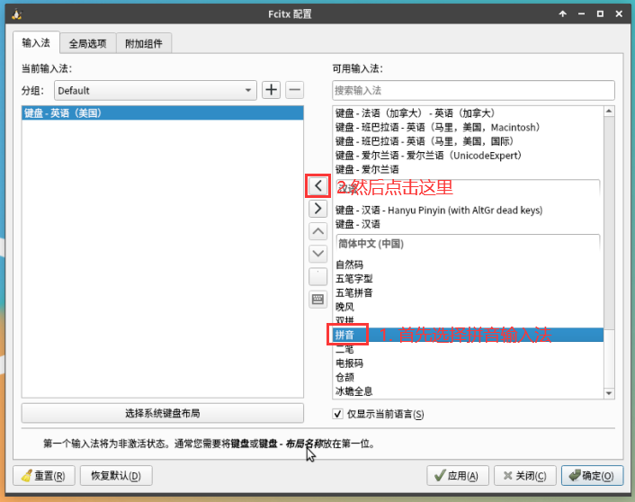
The interface after selecting is shown below, then click OK
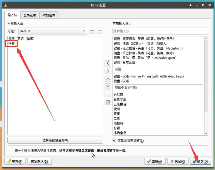
Then we can open the Geany to test Chinese input method.The way to open is shown in the figure below
After opening Geany, the default is an English input method. We can switch into Chinese input method through the Ctrl+Space shortcut keys, and then we can enter Chinese
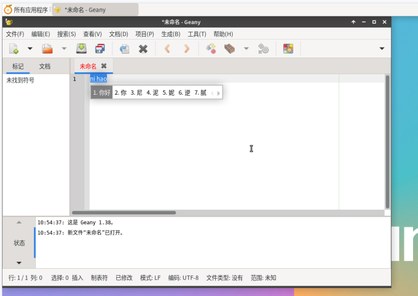


How to remotely log in to the Linux system desktop method
|
Ubuntu Gnome Wayland image does not support NoMachine and VNC described here to remotely log in to the desktop. |
Use NoMachine remote login
|
Make sure the Ubuntu or Debian system installed on the development board is a desktop version. In addition, NoMachine also provides detailed documents. It is strongly recommended to read this document to be familiar with the use of NoMachine. The document links are shown below: |
|
NoMachine supports Windows, Mac, Linux, iOS, and Android platforms, so we can remotely log in to control Orange PI development boards through NoMachine on multiple devices. The following demonstrates the Linux system desktop of the Orange PI development board through NoMachine in Windows. For installation methods for other platforms, please refer to the official documentation of NoMachine. |
|
Before operation, please ensure that the Windows computer and the development board are in the same local area network, and can log in to the Ubuntu or Debian system that can log in to the development board normally |
First download the NoMachine software Linux arm64 DEB version of the installation package, and then install it in the Linux system of the development board.
- Since RK3588 is a SOC of the ARMV8 architecture, the system we use is Ubuntu or Debian, so you need to download NoMachine for ARM ARMv8 DEB installation package here. The download link is shown below:
Note that this download link may change, please recognize the deb package of the Armv8/Arm64 version.
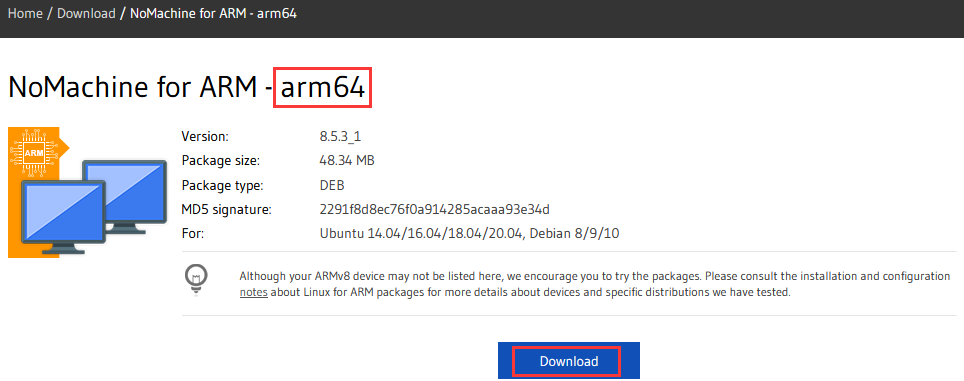
In addition, you can also download the installation package of NoMachine in the official tools

First Enter the remote login software-Nomachine Folder

Then download the arm64 version of the deb installation package
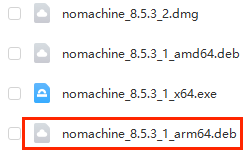
Then upload the downloaded nomachine_x.x.x_x_arm64.deb to the Linux system of the development board
Then use the following command to install NoMachine in the Linux system in the development board
orangepi@orangepi:~$ sudo dpkg -i nomachine_x.x.x_x_arm64_arm64.deb


- Then download the NoMachine software Windows version of the installation package, the download address is shown below
|
Note that this download link may change |

Then install nomachine in Windows. Please restart the computer after installation
Then open NoMachine in Window

After Nomachine is started, it will automatically scan other devices installed in the local area network. After entering the main interface of Nomachine, you can see that the development board is already in the connected device list, and then click the location shown in the red box below in the figure below. You can start logging in to the Linux system desktop of the development board
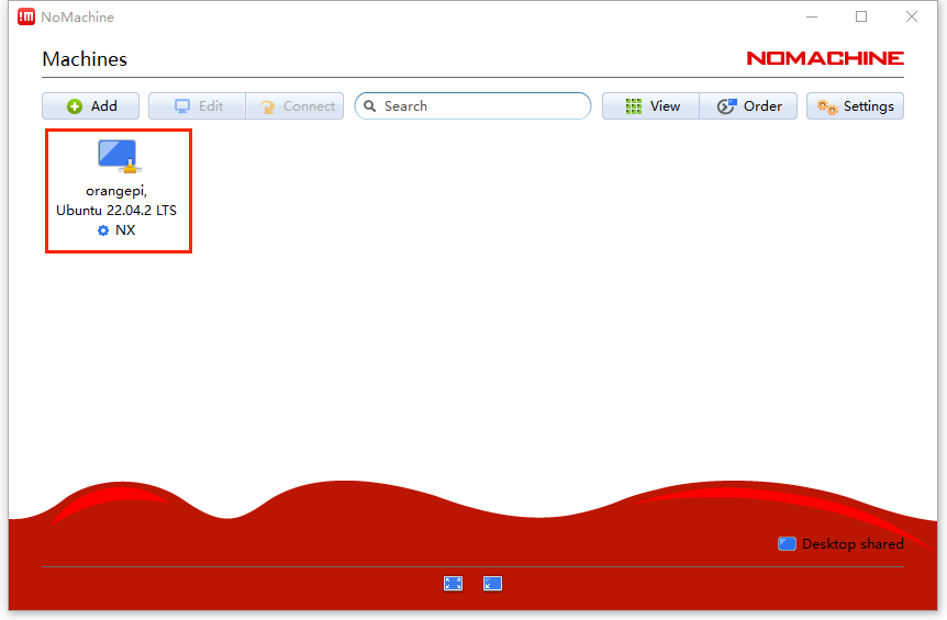
Then click OK
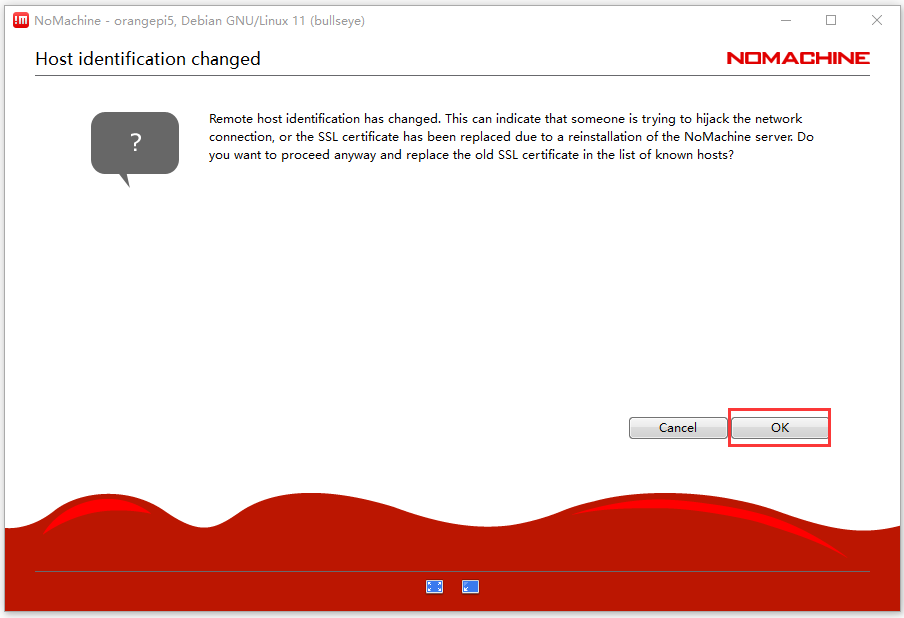
Then enter the username and password of the linux system in the corresponding position in the figure below, and then click OK to start logging in
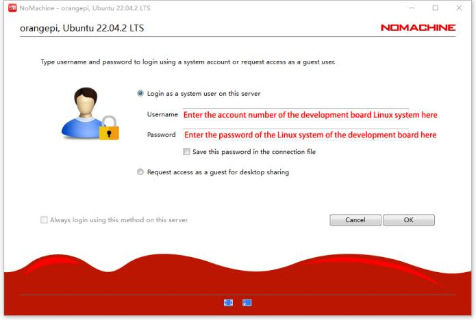
Then click OK in the next interface
Finally, you can see the desktop of the development board Linux system
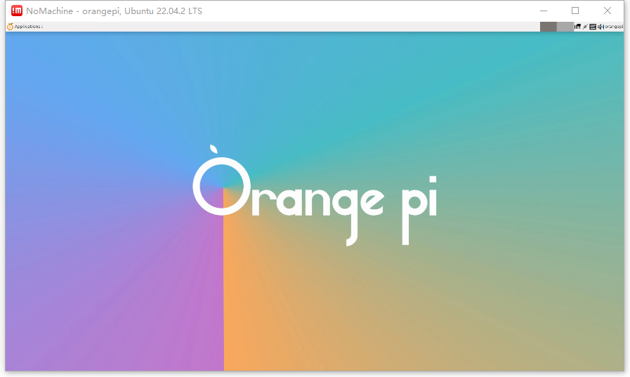


Use VNC remote login
|
Before operation, please ensure that the Windwos computer and the development board are in the same local area network, and you can log in to the Ubuntu or Debian system of the development board normally. Ubuntu 20.04 tests many problems with VNC, please do not use this method. |
First run the set_vnc.sh script settings vnc, and remember to add Sudo permissions
orangepi@orangepi:~$ sudo set_vnc.sh
You will require a password to access your desktops.
Password: #Set the VNC password here, 8 -bit characters
Verify: #Set the VNC password here, 8 -bit characters
Would you like to enter a view-only password (y/n)? n
xauth: file /root/.Xauthority does not exist
New 'X' desktop is orangepi:1
Creating default startup script /root/.vnc/xstartup
Starting applications specified in /root/.vnc/xstartup
Log file is /root/.vnc/orangepi:1.log
Killing Xtightvnc process ID 3047
New 'X' desktop is orangepi:1
Starting applications specified in /root/.vnc/xstartup
Log file is /root/.vnc/orangepi:1.log
The steps of using MobaxTerm software to connect the development board Linux system desktop are shown below:
- First click the session, then select VNC, then fill in the IP address and port of the development board, and finally click OK to confirm
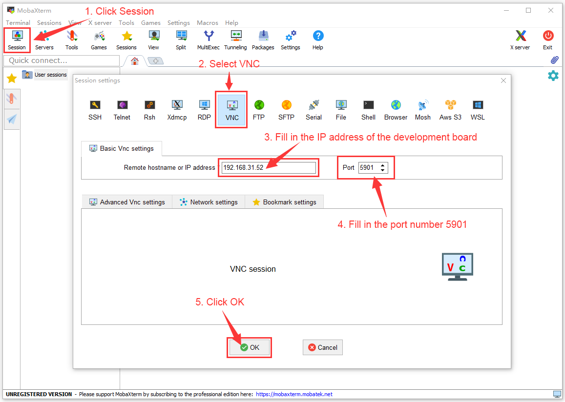
Then enter the password of the previously set VNC
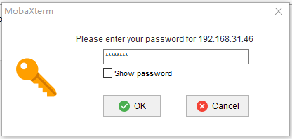
The interface after the login is successfully displayed as shown in the figure below, and then you can remotely operate the desktop of the linux system remotely


Some programming language test supported by thelinux system
Debian Bullseye system
Debian Bullseye is installed with the gcc compilation tool chain by default, which can compile the C language program directly in the Linux system of the development board
The version of the gcc is shown below
orangepi@orangepi:~$ gcc --version
gcc (Debian 10.2.1-6) 10.2.1 20210110
Copyright (C) 2020 Free Software Foundation, Inc.
This is free software; see the source for copying conditions. There is NO
warranty; not even for MERCHANTABILITY or FITNESS FOR A PARTICULAR PURPOSE.
hello_world.c program to write c language
orangepi@orangepi:~$ vim hello_world.c
#include <stdio.h>
int main(void)
{
printf("Hello World!\n");
return 0;
}
Then compile and run hello_world.c
orangepi@orangepi:~$ gcc -o hello_world hello_world.c
orangepi@orangepi:~$ ./hello_world
Hello World!
Debian Bullseye Default with Python3
The specific version of Python is shown below
orangepi@orangepi:~$ python3
Python 3.9.2 (default, Feb 28 2021, 17:03:44)
[GCC 10.2.1 20210110] on linux
Type "help", "copyright", "credits" or "license" for more information.
>>>
Use CTRL+D shortcut key to exit Python's interactive mode.
hello_world.py program in Python language
orangepi@orangepi:~$ vim hello_world.py
print('Hello World!')
The results of running hello_world.py are shown below
orangepi@orangepi:~$ python3 hello_world.py
Hello World!
Debian Bullseye's compilation tool and operating environment without Java default
You can use the following command to install openjdk. The latest version in Debian Bullseye is openjdk-17
orangepi@orangepi:~$ sudo apt install -y openjdk-17-jdk
After installation, you can check the version of Java
orangepi@orangepi:~$ java --version
Edit the hello_world.java of Java version
orangepi@orangepi:~$ vim hello_world.java
public class hello_world
{
public static void main(String[] args)
{
System.out.println("Hello World!");
}
}
Then compile and run hello_world.java
orangepi@orangepi:~$ javac hello_world.java
orangepi@orangepi:~$ java hello_world
Hello World!
Ubuntu Focal system
Ubuntu Focal has a gcc compilation tool chain by default, which can compile the C language program directly in the Linux system of the development board
The version of gcc is shown below
orangepi@orangepi:~$ gcc --version
gcc (Ubuntu 9.4.0-1ubuntu1~20.04.1) 9.4.0
Copyright (C) 2019 Free Software Foundation, Inc.
This is free software; see the source for copying conditions. There is NO
warranty; not even for MERCHANTABILITY or FITNESS FOR A PARTICULAR PURPOSE.
The hello_world.c program that writes c language
orangepi@orangepi:~$ vim hello_world.c
#include <stdio.h>
int main(void)
{
printf("Hello World!\n");
return 0;
}
Then compile and run hello_world.c
orangepi@orangepi:~$ gcc -o hello_world hello_world.c
orangepi@orangepi:~$ ./hello_world
Hello World!
Ubuntu Focal's default installation with Python3
Python3 specific version is shown below
orangepi@orangepi:~$ python3
Python 3.8.10 (default, Nov 14 2022, 12:59:47)
[GCC 9.4.0] on linux
Type "help", "copyright", "credits" or "license" for more information.
>>>
Use CTRL+D shortcut key to exit Python's interactive mode.
The hello_world.py program that writes python language
orangepi@orangepi:~$ vim hello_world.py
print('Hello World!')
The results of running hello_world.py are shown below
orangepi@orangepi:~$ python3 hello_world.py
Hello World!
Ubuntu Focal's compilation tools and operating environment without Java default
You can use the following command to install openjdk-17
orangepi@orangepi:~$ sudo apt install -y openjdk-17-jdk
After installation, you can check the version of the java
orangepi@orangepi:~$ java --version
openjdk 17.0.2 2022-01-18
OpenJDK Runtime Environment (build 17.0.2+8-Ubuntu-120.04)
OpenJDK 64-Bit Server VM (build 17.0.2+8-Ubuntu-120.04, mixed mode, sharing)
Edit the hello_world.java of Java version
orangepi@orangepi:~$ vim hello_world.java
public class hello_world
{
public static void main(String[] args)
{
System.out.println("Hello World!");
}
}
Then compile and run hello_world.java
orangepi@orangepi:~$ javac hello_world.java
orangepi@orangepi:~$ java hello_world
Hello World!
Ubuntu Jammy system
Ubuntu Jammy is equipped with a gcc compilation tool chain by default, which can directly compile the C language program in the Linux system of the development board
The version of gcc is shown below
orangepi@orangepi:~$ gcc --version
gcc (Ubuntu 11.2.0-19ubuntu1) 11.2.0
Copyright (C) 2021 Free Software Foundation, Inc.
This is free software; see the source for copying conditions. There is NO
warranty; not even for MERCHANTABILITY or FITNESS FOR A PARTICULAR PURPOSE.
The hello_world.c program that writes c language
orangepi@orangepi:~$ vim hello_world.c
#include <stdio.h>
int main(void)
{
printf("Hello World!\n");
return 0;
}
Then compile and run hello_world.c
orangepi@orangepi:~$ gcc -o hello_world hello_world.c
orangepi@orangepi:~$ ./hello_world
Hello World!
Ubuntu jammy is installed with Python3 by default
python3 specific version is shown below
orangepi@orangepi:~$ python3
Python 3.10.4 (main, Apr 2 2022, 09:04:19) [GCC 11.2.0] on linux
Type "help", "copyright", "credits" or "license" for more information.
>>>
Use CTRL+D shortcut key to exit Python's interactive mode.
The hello_world.py program that writes python language
orangepi@orangepi:~$ vim hello_world.py
print('Hello World!')
The results of running hello_world.py are shown below
orangepi@orangepi:~$ python3 hello_world.py
Hello World!
Ubuntu Jammy defaults to compile tools and operating environments that are not installed in Java
You can use the following command to install openjdk-18
orangepi@orangepi:~$ sudo apt install -y openjdk-18-jdk
After installation, you can check the version of the java
orangepi@orangepi:~$ java --version
openjdk 18-ea 2022-03-22
OpenJDK Runtime Environment (build 18-ea+36-Ubuntu-1)
OpenJDK 64-Bit Server VM (build 18-ea+36-Ubuntu-1, mixed mode, sharing)
Edit the hello_world.java of Java version
orangepi@orangepi:~$ vim hello_world.java
public class hello_world
{
public static void main(String[] args)
{
System.out.println("Hello World!");
}
}
Then compile and run hello_world.java
orangepi@orangepi:~$ javac hello_world.java
orangepi@orangepi:~$ java hello_world
Hello World!
QT installation method
You can install QT5 and QT Creator with the following scripts
orangepi@orangepi:~$ install_qt.sh
After installation, it will automatically print the QT version number
Ubuntu20.04's own QT version is 5.12.8
orangepi@orangepi:~$ install_qt.sh
......
QMake version 3.1
Using Qt version 5.12.8 in /usr/lib/aarch64-linux-gnu
Ubuntu22.04's own QT version is 5.15.3
orangepi@orangepi:~$ install_qt.sh
......
QMake version 3.1
Using Qt version 5.15.3 in /usr/lib/aarch64-linux-gnu
The QT version comes with Debian11 is 5.15.2
orangepi@orangepi:~$ install_qt.sh
......
QMake version 3.1
Using Qt version 5.15.2 in /usr/lib/aarch64-linux-gnu
The QT version that comes with Debian12 is 5.15.8
orangepi@orangepi:~$ install_qt.sh
......
QMake version 3.1
Using Qt version 5.15.8 in /usr/lib/aarch64-linux-gnu
Then you can see the lax icon of QT Creator in Applications

You can also use the following command to open QT Creator
orangepi@orangepi:~$ qtcreator
During the startup process of QT and QT applications, if the error below is prompted, please ignore it directly. This error will not affect the operation of the application.
libGL error: failed to create dri screen
libGL error: failed to load driver: rockchip
libGL error: failed to create dri screen
libGL error: failed to load driver: rockchip
The interface after the QT Creator is opened is shown below
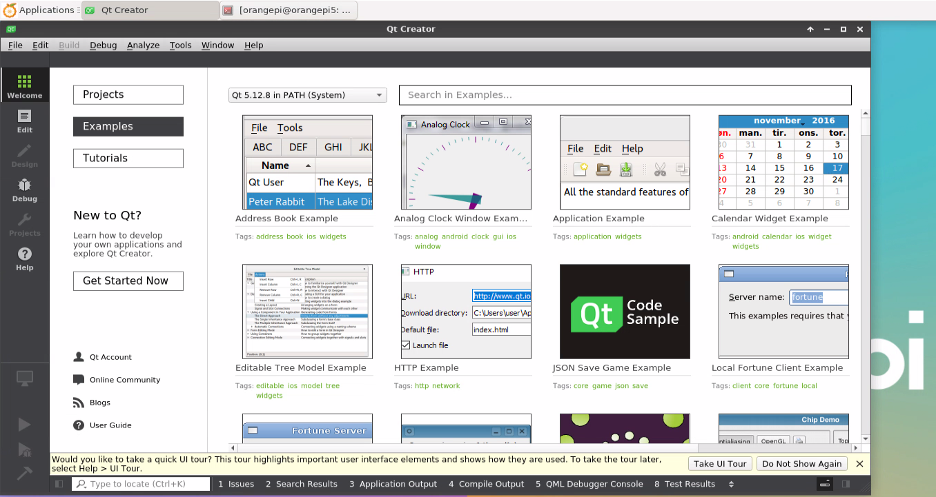
The version of QT Creator is shown below
The default version of QT Creator in Ubuntu20.04 is shown below
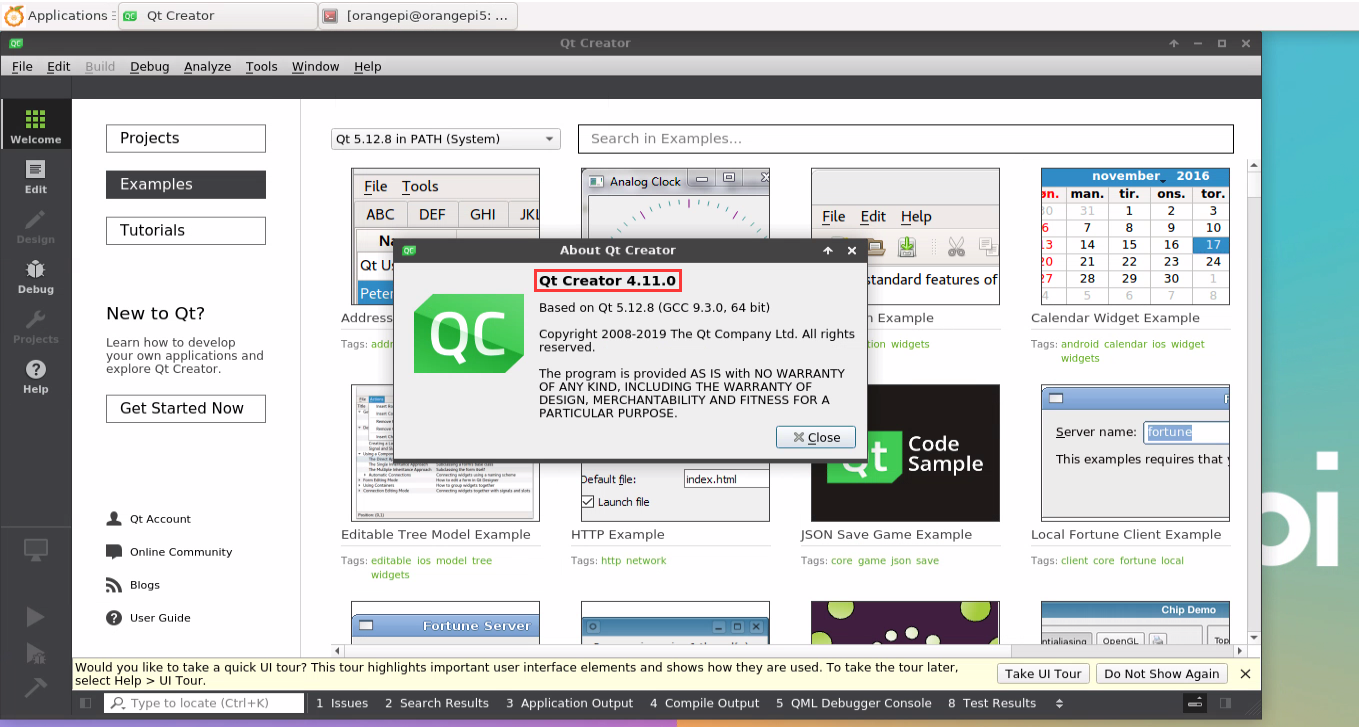
The default version of QT Creator in Ubuntu22.04 is shown below
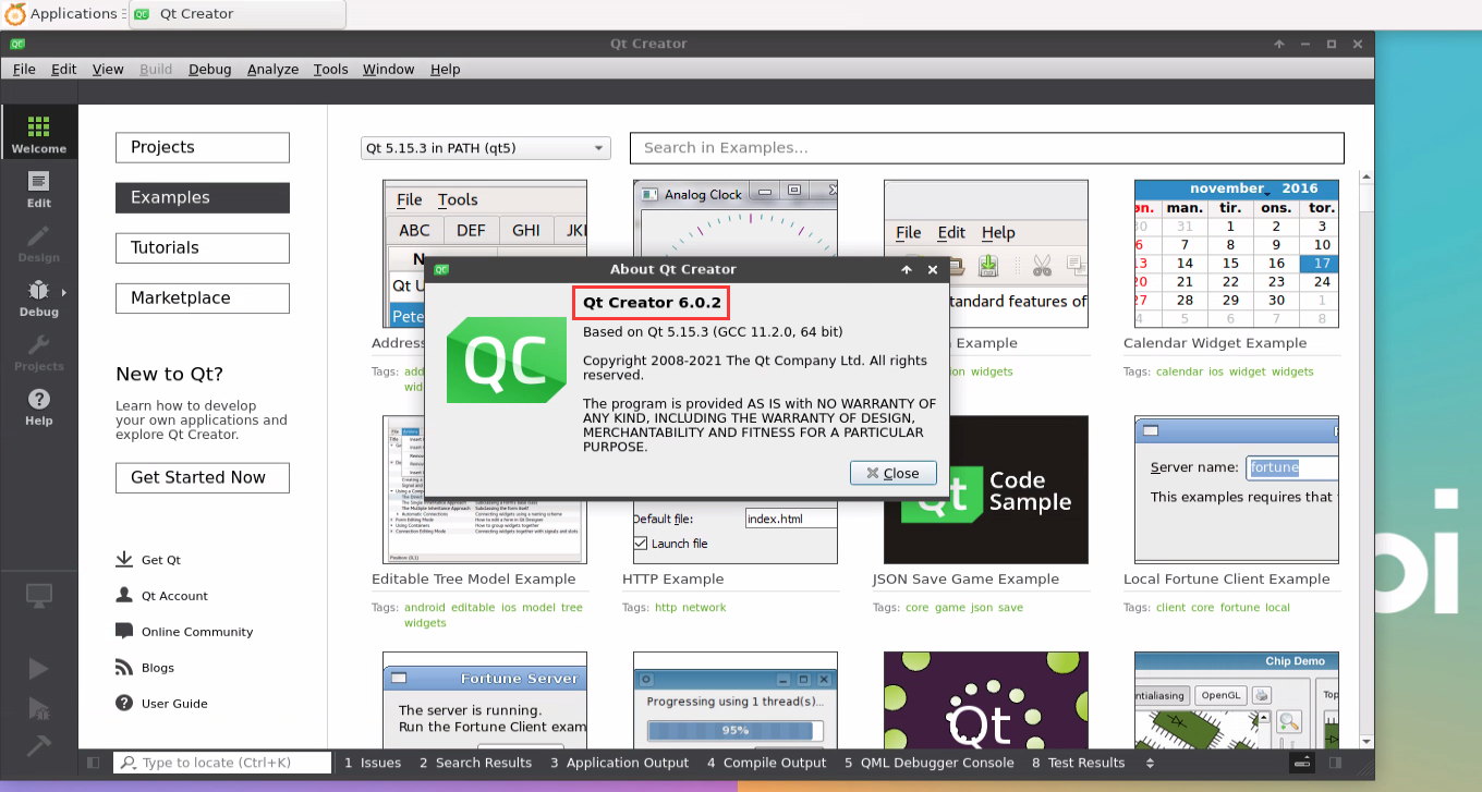
The default version of QT Creator in Debian11 is shown below
The default version of QT Creator in Debian12 is as follows
Then set the QT
First open Help->About Plugins...
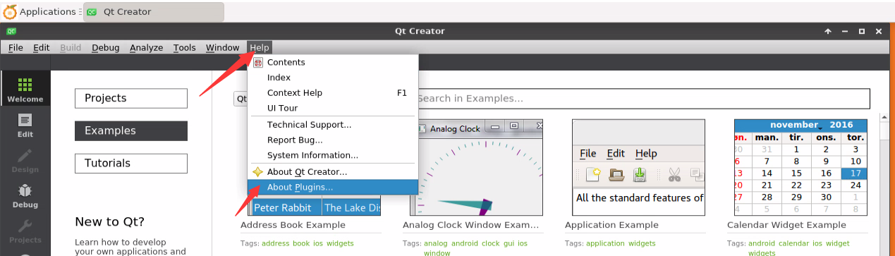
Then remove the hook of ClangCodeModel
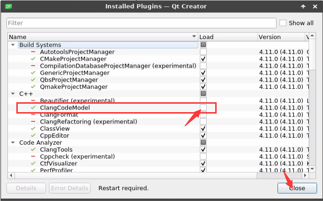
After setting, you need to restart Qt Creator
Then make sure the GCC compiler used by QT Creator, if the default is Clang, please modify it to GCC
Debian12 please skip this step.
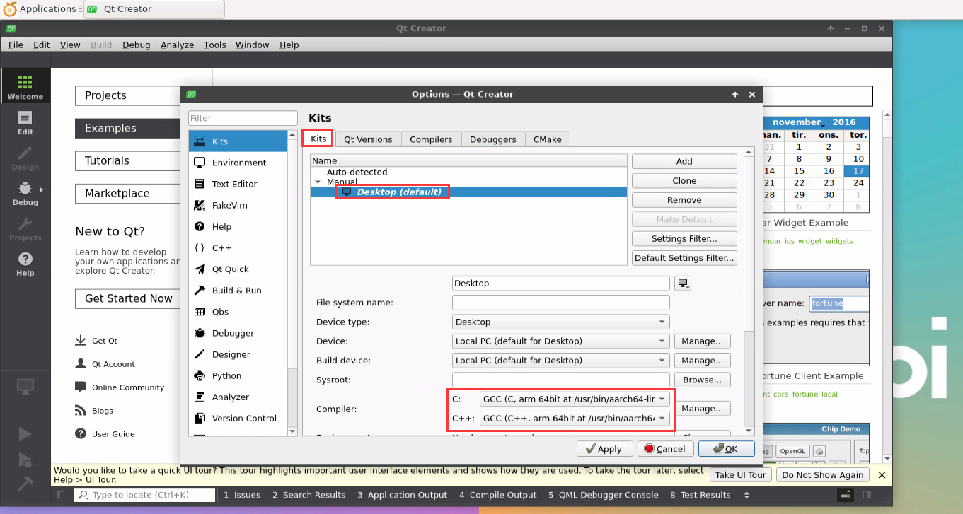
Then you can open an example code
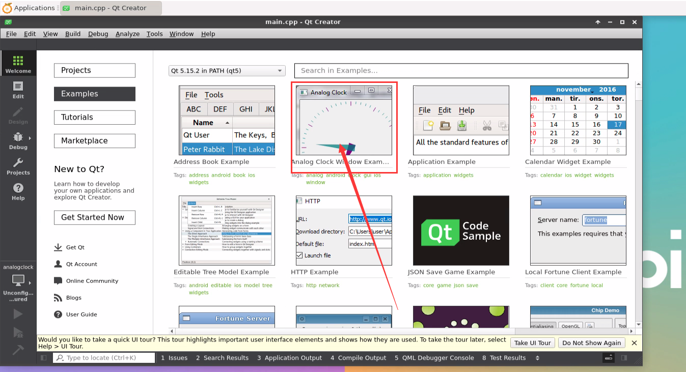
After clicking the example code, you will automatically open the corresponding description document. You can carefully look at the instructions for the use
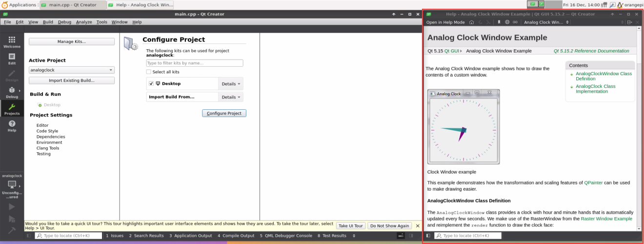
Then click Configure Project
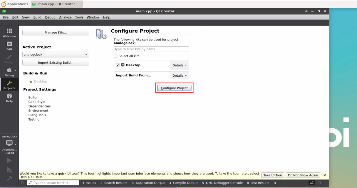
Then click the sample code under the green triangle compilation and run in the lower left corner
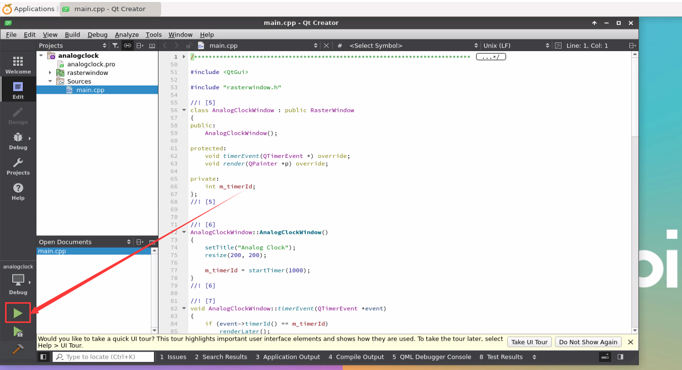
After waiting for a while, the interface shown in the figure below will pop up. At this time, it means that QT can compile and run normally
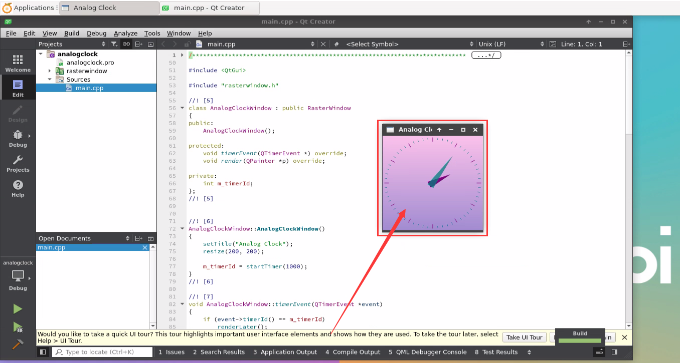
Reference information
https://wiki.qt.io/Install_Qt_5_on_Ubuntu


ROS installation method
Ubuntu 20.04 method of installing ROS 1 Noetic
- The current active version of ROS 1 is shown below. The recommended version is Noetic Ninjemys


ROS 1 Noetic Ninjemys' official installation document links are shown below:
Ubuntu 20.04 is recommended in the official installation document of ROS Noetic Ninjemys, so please make sure that the system used in the development board is Ubuntu20.04 desktop version system
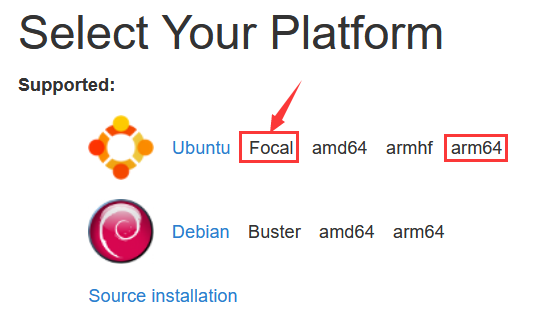
Then install Ros1 with the following script
orangepi@orangepi5plus:~$ install_ros.sh ros1
Before using the ROS tool, you need to initialize ROSDEP first, and then install some system dependencies and core components in some ROS when compiling the source code
- The read operation timed out
- rosdep update

|
Note that the following commands need to ensure that the development board can access GitHub normally, otherwise it will report an error due to network problems.
Hit https://raw.githubusercontent.com/ros/rosdistro/master/rosdep/base.yaml ERROR: error loading sources list: |
|
orangepi@orangepi:~$ source /opt/ros/noetic/setup.bash orangepi@orangepi:~$ sudo rosdep init Wrote /etc/ros/rosdep/sources.list.d/20-default.list Recommended: please run
orangepi@orangepi:~$ rosdep update reading in sources list data from /etc/ros/rosdep/sources.list.d Hit https://raw.githubusercontent.com/ros/rosdistro/master/rosdep/osx-homebrew.yaml Hit https://raw.githubusercontent.com/ros/rosdistro/master/rosdep/base.yaml Hit https://raw.githubusercontent.com/ros/rosdistro/master/rosdep/python.yaml Hit https://raw.githubusercontent.com/ros/rosdistro/master/rosdep/ruby.yaml Hit https://raw.githubusercontent.com/ros/rosdistro/master/releases/fuerte.yaml Query rosdistro index https://raw.githubusercontent.com/ros/rosdistro/master/index-v4.yaml Skip end-of-life distro "ardent" Skip end-of-life distro "bouncy" Skip end-of-life distro "crystal" Skip end-of-life distro "dashing" Skip end-of-life distro "eloquent" Add distro "foxy" Add distro "galactic" Skip end-of-life distro "groovy" Add distro "humble" Skip end-of-life distro "hydro" Skip end-of-life distro "indigo" Skip end-of-life distro "jade" Skip end-of-life distro "kinetic" Skip end-of-life distro "lunar" Add distro "melodic" Add distro "noetic" Add distro "rolling" updated cache in /home/orangepi/.ros/rosdep/sources.cache |
Then open a command line window on the desktop, and then use the test_ros.sh script to start a small turtle routine to test whether the ROS can be used normally
orangepi@orangepi:~$ test_ros.sh
After running the test_ros.sh script, a small turtle shown in the figure below will pop up
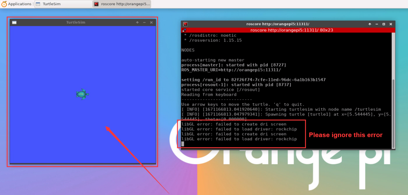
Then please keep the terminal window just open at the top


At this time, press the direction button on the keyboard to control the small turtles up, down, left and right
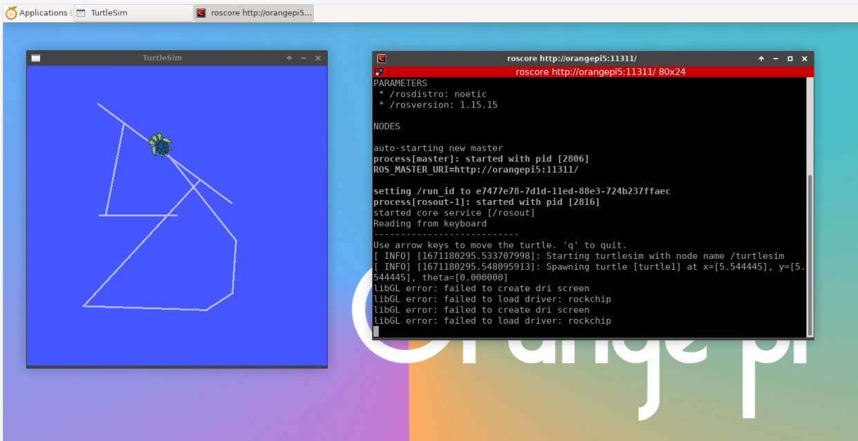

Ubuntu20.04 The method of installing ROS 2 Galactic
The current active version of ROS 2 is shown below. The recommended version is Galactic Geochelone


ROS 2 Galactic Geochelone's official installation document link is shown below:
docs.ros.org/en/galactic/Installation.html
http://docs.ros.org/en/galactic/Installation/Ubuntu-Install-Debians.html
ROS 2 Galactic Geochelone's official installation document is recommended to use Ubuntu 20.04, so please make sure that the system used in the development board is Ubuntu20.04 desktop version system. There are several ways to install ROS 2. The following demonstrates install the Ros 2 Galactic Geochelone by Debian packages
You can install ROS2 with install_ros.sh script
orangepi@orangepi:~$ install_ros.sh ros2
install_ros.sh script will automatically run the ros2 -h command after ros2 is installed. If you can see the printing below, it means that ros2 installation is complete
usage: ros2 [-h] Call `ros2 <command> -h` for more detailed usage. ...
ros2 is an extensible command-line tool for ROS 2.
optional arguments:
-h, --help show this help message and exit
Commands:
action Various action related sub-commands
bag Various rosbag related sub-commands
component Various component related sub-commands
daemon Various daemon related sub-commands
doctor Check ROS setup and other potential issues
interface Show information about ROS interfaces
launch Run a launch file
lifecycle Various lifecycle related sub-commands
multicast Various multicast related sub-commands
node Various node related sub-commands
param Various param related sub-commands
pkg Various package related sub-commands
run Run a package specific executable
security Various security related sub-commands
service Various service related sub-commands
topic Various topic related sub-commands
wtf Use `wtf` as alias to `doctor`
Call `ros2 <command> -h` for more detailed usage.
Then you can use the test_ros.sh script to test whether the ROS 2 is successfully installed. If you can see the printing below, it means that the ROS 2 can run normally
orangepi@orangepi5plus:~$ test_ros.sh
[INFO] [1671174101.200091527] [talker]: Publishing: 'Hello World: 1'
[INFO] [1671174101.235661048] [listener]: I heard: [Hello World: 1]
[INFO] [1671174102.199572327] [talker]: Publishing: 'Hello World: 2'
[INFO] [1671174102.204196299] [listener]: I heard: [Hello World: 2]
[INFO] [1671174103.199580322] [talker]: Publishing: 'Hello World: 3'
[INFO] [1671174103.204019965] [listener]: I heard: [Hello World: 3]
Run the following command to open rviz2
orangepi@orangepi:~$ source /opt/ros/galactic/setup.bash
orangepi@orangepi:~$ ros2 run rviz2 rviz2
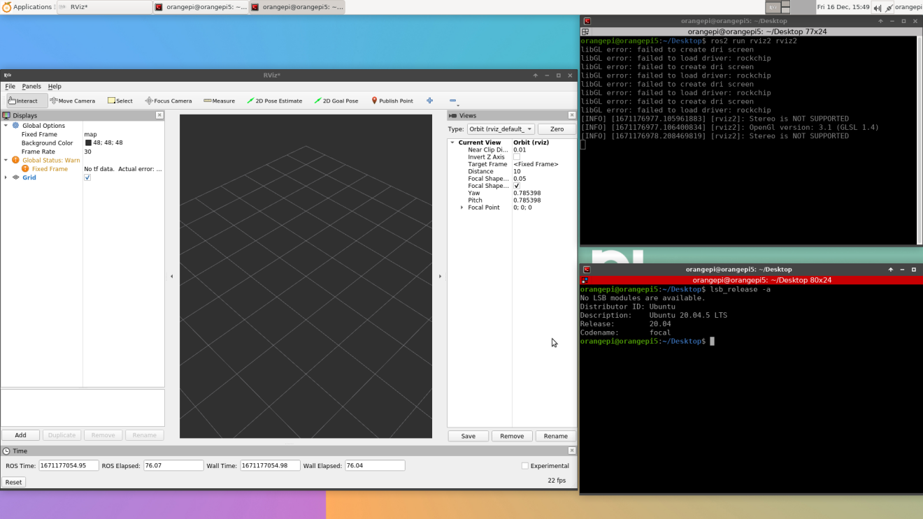
How to use ROS, please refer to the document of ROS 2


Ubuntu22.04 to install ROS 2 Humble
install ROS2 with install_ros.sh script
orangepi@orangepi:~$ install_ros.sh ros2
install_ros.sh script will automatically run the ros2 -h command after ROS2 is installed. If you can see the following printing, it means that ROS2 installation is complete.
usage: ros2 [-h] Call `ros2 <command> -h` for more detailed usage. ...
ros2 is an extensible command-line tool for ROS 2.
optional arguments:
-h, --help show this help message and exit
Commands:
action Various action related sub-commands
bag Various rosbag related sub-commands
component Various component related sub-commands
daemon Various daemon related sub-commands
doctor Check ROS setup and other potential issues
interface Show information about ROS interfaces
launch Run a launch file
lifecycle Various lifecycle related sub-commands
multicast Various multicast related sub-commands
node Various node related sub-commands
param Various param related sub-commands
pkg Various package related sub-commands
run Run a package specific executable
security Various security related sub-commands
service Various service related sub-commands
topic Various topic related sub-commands
wtf Use `wtf` as alias to `doctor`
Call `ros2 <command> -h` for more detailed usage.
Then you can use the test_ros.sh script to test whether the ROS 2 is successfully installed. If you can see the printing below, it means that ROS 2 can run normally
orangepi@orangepi5plus:~$ test_ros.sh
[INFO] [1671174101.200091527] [talker]: Publishing: 'Hello World: 1'
[INFO] [1671174101.235661048] [listener]: I heard: [Hello World: 1]
[INFO] [1671174102.199572327] [talker]: Publishing: 'Hello World: 2'
[INFO] [1671174102.204196299] [listener]: I heard: [Hello World: 2]
[INFO] [1671174103.199580322] [talker]: Publishing: 'Hello World: 3'
[INFO] [1671174103.204019965] [listener]: I heard: [Hello World: 3]
Run the following command to open rviz2
orangepi@orangepi:~$ source /opt/ros/humble/setup.bash
orangepi@orangepi:~$ ros2 run rviz2 rviz2
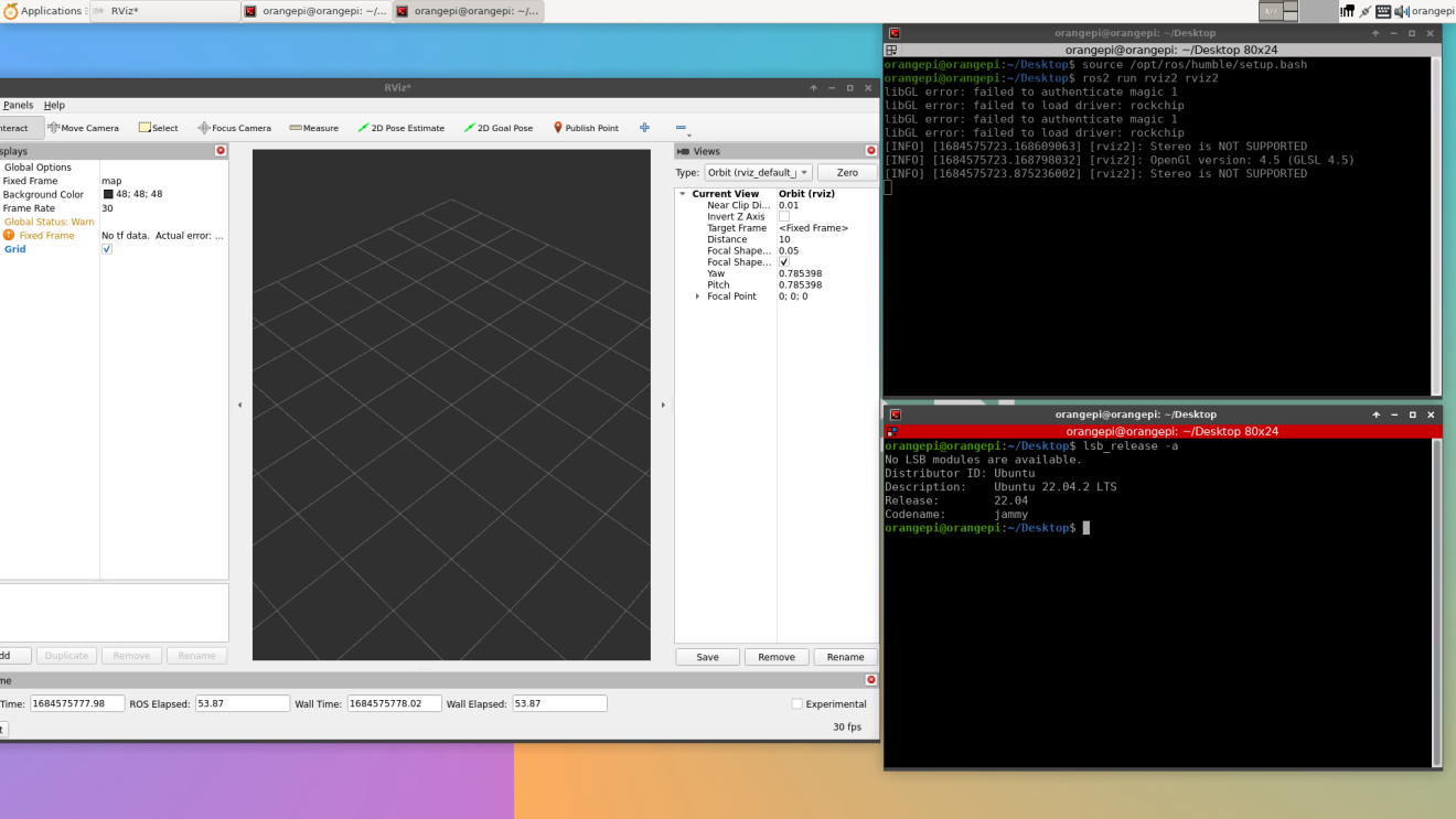
Reference document
http://docs.ros.org/en/humble/index.html
http://docs.ros.org/en/humble/Installation/Ubuntu-Install-Debians.html

The method of installing the kernel header file
The linux image released by OPI defaults to the DEB package of the kernel header file. The location is /opt/
orangepi@orangepi5plus:~$ ls /opt/linux-headers*
/opt/linux-headers-legacy-rockchip-rk3588_x.x.x_arm64.deb
Use the following command to install the deb package of the kernel header file
The name of the kernel file deb package needs to be replaced with the actual name, please don't copy it.
orangepi@orangepi:~$ sudo dpkg -i /opt/linux-headers-legacy-rockchip-rk3588_1.x.x_arm64.deb
After installation, you can see the folder where the kernel header file is located under the/usr/src
orangepi@orangepi:~$ ls /usr/src
linux-headers-5.10.110-rockchip-rk3588
Then you can write a Hello kernel module to test the kernel header file
First write the code of the Hello kernel module, as shown below:
orangepi@orangepi:~$ vim hello.c
#include <linux/init.h>
#include <linux/module.h>
static int hello_init(void)
{
printk("Hello Orange Pi -- init\n");
return 0;
}
static void hello_exit(void)
{
printk("Hello Orange Pi -- exit\n");
return;
}
module_init(hello_init);
module_exit(hello_exit);
MODULE_LICENSE("GPL");
Then write a makefile file that compiles the Hello kernel module, as shown below:
orangepi@orangepi:~$ vim Makefile
ifneq ($(KERNELRELEASE),)
obj-m:=hello.o
else
KDIR :=/lib/modules/$(shell uname -r)/build
PWD :=$(shell pwd)
all:
make -C $(KDIR) M=$(PWD) modules
clean:
rm -f *.ko *.o *.mod.o *.mod *.symvers *.cmd *.mod.c *.order
endif
Then use the make command to compile the Hello kernel module, and the output of the compilation process is shown below:
If you compile the code you copy here, if you have any problems, go to the official tool to download the source code and upload it to the Linux system of the development board for testing

orangepi@orangepi:~$ make
make -C /lib/modules/5.10.110-rockchip-rk3588/build M=/home/orangepi modules
make[1]: Entering directory '/usr/src/linux-headers-5.10.110-rockchip-rk3588'
CC [M] /home/orangepi/hello.o
MODPOST /home/orangepi/Module.symvers
CC [M] /home/orangepi/hello.mod.o
LD [M] /home/orangepi/hello.ko
make[1]: Leaving directory '/usr/src/linux-headers-5.10.110-rockchip-rk3588'
After compiling, the hello.ko kernel module will be generated
orangepi@orangepi:~$ ls *.ko
hello.ko
Use the insmod command to insert the hello.ko kernel module into the kernel
orangepi@orangepi:~$ sudo insmod hello.ko
Then use the demsg command to view the output of the hello.ko kernel module. If you can see the output instructions below, the hello.ko kernel module is loaded correctly
orangepi@orangepi:~$ dmesg | grep "Hello"
[ 2871.893988] Hello Orange Pi -- init
Use the rmmod command to uninstall the hello.ko kernel module
orangepi@orangepi:~$ sudo rmmod hello
orangepi@orangepi:~$ dmesg | grep "Hello"
[ 2871.893988] Hello Orange Pi -- init
[ 3173.800892] Hello Orange Pi -- exit

How to use 10.1 inch MIPI LCD screen
10.1 -inch MIPI screen assembly method
First prepare the required accessories
10.1 -inch MIPI LCD display+touch screen (this screen and OPI5/OPI5B universal)

Screen divert plate+31pin to 40pin line
30pin mipi line

12pin touch screen row line
According to the figure below, the 12PIN touch screen row, 31PIN to 40PIN ducts, and 30pin MIPI cables get on the screen dial board. Pay attention to line of the touch screen the blue insulation face under. If you get an error, it will cause no display or unable to touch

Place the connected rotor connected to the puzzle on the MIPI LCD screen according to the figure below, and connect the MIPI LCD screen and the rotary board through 31PIN to 40Pin row


Then connect the touch screen and the rotor board through the 12PIN touch screen line, pay attention to the orientation of the insulating surface.
Finally connect to the LCD interface of the development board through the 30PIN MIPI duct
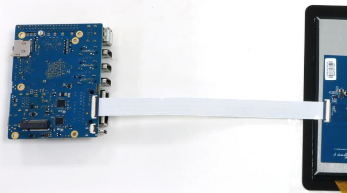
Note that the touch interface below is not used for the LCD MIPI screen. It is currently a spare interface and cannot be used
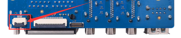


Open the 10.1 -inch MIPI LCD screen configuration
The Linux image defaults to the configuration of the mipi lcd screen by default. If you need to use the mipi lcd screen, you need to open it manually.
The position of the development board MIPI LCD screen interface is shown below:
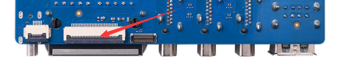
The steps of opening the MIPI LCD configuration are shown below:
First run the orangePi-config. Ordinary users remember to add Sudo permissions
orangepi@orangepi:~$ sudo orangepi-config
Then choose System
Then choos Hardware
Then use the keyboard orientation to position the opi5plus-lcd, and then use the space to select

Then select <Save>
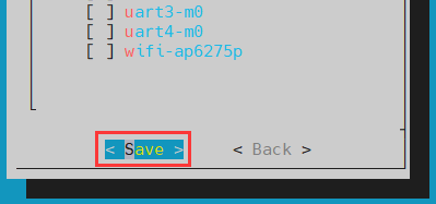
Then sele <Back>
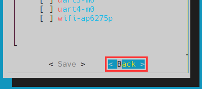
Then select the <Reboot> restart system to make the configuration effective
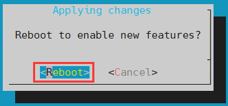
After starting, you can see the display of the LCD screen as shown below (the default is vertical screen):


The server version of the image rotation display direction method
Add extrargs = fbcon = rotate: The direction to rotate is in /boot/orangepiEnv.txt. This configuration can set the direction of the LINUX system of the server version,Among them, fbcon=rotate: The following numbers can be set to be set to
0: Normal screen (default vertical screen)
1: Turn 90 degrees clock
2: Flip 180 degrees
3: Turn to 270 degrees clock
orangepi@orangepi:~$ sudo vim /boot/orangepiEnv.txt
overlays=opi5plus-lcd
extraargs=cma=128M fbcon=rotate:3
Note that if/boot/orangepienv.txt is configured in the default default exiArgs = CMA = 128M, fbcon = rotate: 3 The configuration can be added to the extensraargs = cma = 128m (need to be separated by spaces).
Then restart the Linux system to see that the direction of the LCD screen display has been rotated
The desktop image rotation display and touch direction method
First open Display settings in the Linux system
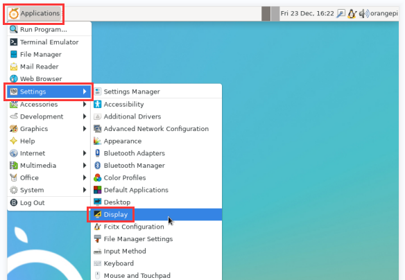
Then select the direction you want to rotate in the Rotation
None: Not rotate
Left: Rotate 90 degrees to the left
Inverted: Flipting up and down is equivalent to rotating 180 > degrees
Right: Rotate 90 degrees to the right
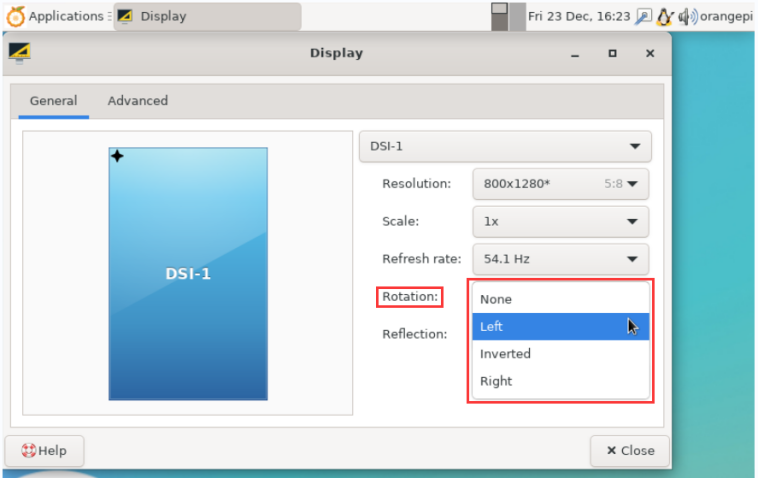
Then click Apply
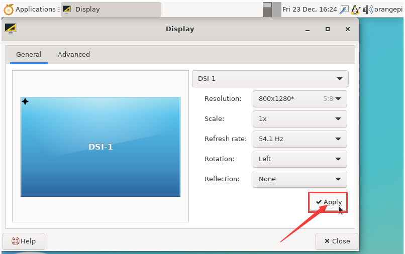
Then click Keep this configuration
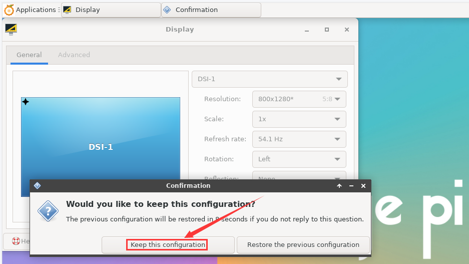
At this time, the screen display has been rotated, and then the Display program is turned off
The above steps will only select the display direction, and it will not rotate the direction of touch. Use set_lcd_rotate.sh script to rotate the direction of touch. After this script is set, it will be automatically restarted, and then you can test whether the touch can be used normally
None: Not rotate
orangepi@orangepi:~$ set_lcd_rotate.sh none
Left: Rotate 90 degrees to the left
orangepi@orangepi:~$ set_lcd_rotate.sh left
Inverted: Flipting up and down, equivalent to rotating 180 > degrees
orangepi@orangepi:~$ set_lcd_rotate.sh inverted
Right: Rotate 90 degrees to the right
orangepi@orangepi:~$ set_lcd_rotate.sh right
set_lcd_rotate.sh The script mainly does four things:
Rotate the direction of Framebuffer displayed
The direction of rotating touch
Close the boot LOGO
Restart the system
The direction of the rotation touch is achieved by adding Option TransformationMatrix""x x x x x x x x x"in /usr/share/X11/xorg.conf.d/40-libinput.conf. Among them, "x x x x x x x x x" is different in different directions.


Touch rotation reference materials
Instructions for opening the logo use instructions
The default LOGO default is displayed in the desktop version of the system
Set the bootlogo variable to false in /boot/orangepiEnv.txt to turn off the switch to the LOGO
orangepi@orangepi:~$ sudo vim /boot/orangepiEnv.txt
verbosity=1
bootlogo=false
Set the bootlogo variable to true in /boot/orangepiEnv.txt to turn the opening and the logo
orangepi@orangepi:~$ sudo vim /boot/orangepiEnv.txt
verbosity=1
bootlogo=true
The position of the LOGO picture in the Linux system is
/usr/share/plymouth/themes/orangepi/watermark.png
After replacing the start -up logo picture, you need to run the command to take effect
orangepi@orangepi:~$ sudo update-initramfs -u
Test methods for OV13850 and OV13855 MIPI camera
At present, the development board supports two MIPI cameras, OV13850 and OV13855. The specific pictures are shown below:
OV13850 camera at 13 million MIPI interface
13 million MIPI interface OV13855 camera
The rotary board used by OV13850 and OV13855 cameras is the same as the FPC cable, but the two cameras are different from the position on the rotary board. The FPC lines are shown in the figure below. Please note that the FPC line is directed. It is marked that the TO MB must be inserted into the camera interface of the development board. It is marked that the end of TO CAMERA needs to be inserted on the camera transfer board.

There are a total of 3 cameras on the camera to connect to the board, which can only be used one at the same time, as shown in the figure below, among which:
No. 1 connect with OV13850 camera
No. 2 interface OV13855 camera
The No. 3 interface is not used, just ignore it.

Orange Pi 5 Plus development board has a total of 1 camera interface, which is shown below:

The method of the camera inserted in the development board interface is shown below:

After connecting the camera to the development board, we can use the following method to test the camera:
First run the orangepi-config. Ordinary users remember to add sudo permissions
orangepi@orangepi:~$ sudo orangepi-config
Then select System
Then choose Hardware
Then use the keyboard to locate the position shown in the figure below, and then use the camera you want to open in the space. Among them, opi5plus-ov13850 means using an OV13850 camera, opi5plus-ov13855 indicates the use of OV13855 camera.

Then choose <Save>
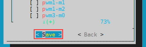
Then choose <Back>

Then select the<Reboot> restart system to make the configuration effective
Then open a terminal in the desktop system and run the script below
orangepi@orangepi:~$ test_camera.sh
Then you can see the preview of the camera
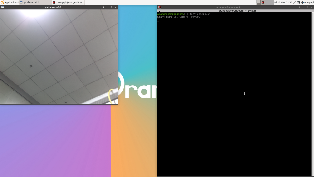


Test method for infrared receiving
There is an infrared receiver on the development board, which is connected to thePWM15_IR_M1 pin. The method of checking the key value received by infrared is shown below:
First run the evtest command in the command line, and then select the device serial number corresponding to the febf0030.pwm
orangepi@orangepi:~$ evtest
No device specified, trying to scan all of /dev/input/event*
Not running as root, no devices may be available.
Available devices:
/dev/input/event0: febf0030.pwm
/dev/input/event1: rk805 pwrkey
/dev/input/event2: rockchip,dp0 rockchip,dp0
/dev/input/event3: rockchip-hdmi0 rockchip-hdmi0
/dev/input/event4: rockchip-hdmi1 rockchip-hdmi1
/dev/input/event5: headset-keys
/dev/input/event6: rockchip,es8388 Headset
/dev/input/event7: adc-keys
/dev/input/event8: SONiX USB Keyboard
/dev/input/event9: SONiX USB Keyboard Consumer Control
/dev/input/event10: SONiX USB Keyboard System Control
/dev/input/event11: PixArt USB Optical Mouse
Select the device event number [0-11]: 0 #Select the serial number corresponding to Febf0030.pwm here
Input driver version is 1.0.1
Input device ID: bus 0x19 vendor 0x524b product 0x6 version 0x100
Input device name: "febf0030.pwm"
Supported events:
Event type 0 (EV_SYN)
Event type 1 (EV_KEY)
Event code 2 (KEY_1)
Event code 3 (KEY_2)
Event code 4 (KEY_3)
Event code 5 (KEY_4)
Event code 6 (KEY_5)
Event code 7 (KEY_6)
Event code 8 (KEY_7)
Event code 9 (KEY_8)
Event code 10 (KEY_9)
Event code 11 (KEY_0)
Event code 28 (KEY_ENTER)
Event code 102 (KEY_HOME)
Event code 103 (KEY_UP)
Event code 105 (KEY_LEFT)
Event code 106 (KEY_RIGHT)
Event code 108 (KEY_DOWN)
Event code 113 (KEY_MUTE)
Event code 114 (KEY_VOLUMEDOWN)
Event code 115 (KEY_VOLUMEUP)
Event code 116 (KEY_POWER)
Event code 139 (KEY_MENU)
Event code 143 (KEY_WAKEUP)
Event code 158 (KEY_BACK)
Event code 217 (KEY_SEARCH)
Event code 388 (KEY_TEXT)
Properties:
Testing ... (interrupt to exit)
Then need to prepare an infrared remote control shown in the figure below
Note: The Linux system provided by the Orange School only supports the remote control provided by the Orange School. The remote control of the TV or air conditioner cannot be used.

Then press the button on the infrared receiver on the development board to press the button on the remote control. The position of the infrared receiver on the development board is as shown in the figure below:
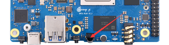
Then you can see that evtest will print the received key value
......
Event code 217 (KEY_SEARCH)
Event code 388 (KEY_TEXT)
Properties:
Testing ... (interrupt to exit)
Event: time 1684152321.834907, type 1 (EV_KEY), code 2 (KEY_1), value 1
Event: time 1684152321.834907, -------------- SYN_REPORT ------------
Event: time 1684152322.017512, type 1 (EV_KEY), code 2 (KEY_1), value 0
Event: time 1684152324.630961, -------------- SYN_REPORT ------------
Event: time 1684152326.482359, type 1 (EV_KEY), code 106 (KEY_RIGHT), value 1
Event: time 1684152326.482359, -------------- SYN_REPORT ------------
Event: time 1684152326.667633, type 1 (EV_KEY), code 106 (KEY_RIGHT), value 0
Event: time 1684152328.427632, -------------- SYN_REPORT ------------
Event: time 1684152330.761986, type 1 (EV_KEY), code 116 (KEY_POWER), value 1
Event: time 1684152330.761986, -------------- SYN_REPORT ------------
Event: time 1684152330.944243, type 1 (EV_KEY), code 116 (KEY_POWER), value 0
Event: time 1684152330.944243, -------------- SYN_REPORT ------------


The method to use RTC
A RTC battery interface is reserved on the development board, which is shown below:
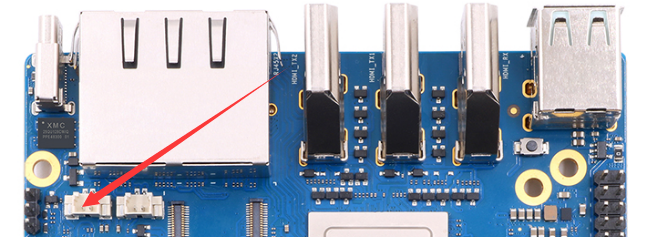
The RTC battery that needs to be purchased is shown below. The interface is 2pin, 1.25mm spacing
The RTC chip used on the development board is Hym8563TS. This chip has the following characteristics:
Wide work voltage range:1.0~5.5v
Low dormant current:Typical value 0.25μA(VDD =3.0V, TA =25°C)
After connecting the RTC battery on the development board, use the following method to test whether the RTC has been working normally:
First turn on the system, then record the current time of the > system
Then use the Poweroff command to turn off the system normally
Then unplug the power supply to ensure that the development > board does not access the network cable and wireless WiFi, and > wait a few minutes
Then start the system again. If you see the time walk forward > for a few minutes after entering the system, it means that the > RTC module and the battery work normally
See the command of the RTC information through the ProcFS interface of the Linux system
orangepi@orangepi:~$ cat /proc/driver/rtc
rtc_time : 06:07:40
rtc_date : 2023-05-22
alrm_time : 03:36:00
alrm_date : 2023-05-23
alarm_IRQ : no
alrm_pending : no
update IRQ enabled : no
periodic IRQ enabled : no
periodic IRQ frequency : 1
max user IRQ frequency : 64
24hr : yes
How to use the cooling PWM fan
The development board is used for interfaces that connect the heat sink fan. The interface specifications are 2pin 1.25mm spacing, 5V voltage driver, and the position of the fan interface is shown in the figure below:
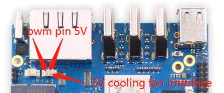
The fan on the development board can adjust the speed and switch through PWM, and the PWM pins used are PWM3_IR_M1
The Linux system uses the pwm-fan driver to control the fan by default. The DTS configuration used is shown below:
orange-pi-5.10-rk3588/arch/arm64/boot/dts/rockchip/rk3588-orangepi-5-plus.dts
fan: pwm-fan {
compatible = "pwm-fan";
#cooling-cells = <2>;
pwms = <&pwm3 0 50000 0>;
cooling-levels = <0 50 100 150 200 255>;
rockchip,temp-trips = <
50000 1
55000 2
60000 3
65000 4
70000 5
>;
status = "okay";
};
Among it:
pwms = <&pwm3 0 50000 0>:The PWM of the control fan is PWM3.
cooling-levels = <0 50 100 150 200 255>:It is used to configure the gear of the speed (PWM duty cycle). The number and size of the gear can be defined by itself. Here are 6 gears. The range of the speed is 0-255.
rockchip,temp-trips:It is used to configure the corresponding relationship between the CPU temperature and the fan speed gear. It can be adjusted according to actual needs. The above configuration 50 degrees corresponding gear 1, 70 degrees to the corresponding gear 5.
It is normal to find that the fan does not turn after turning, because the temperature of the CPU after booting is generally lower than 50 degrees. Only when the temperature of the CPU reaches 50 degrees, the fan will start to turn.
Use the following commands to make all CPUs run, and then you can see that the fan will start working:
orangepi@orangepi:~$ for i in $(seq 0 $(( $(nproc --all) - 1)) ); do (taskset -c $i yes > /dev/null &); done
How to use the ZFS file system
|
The latest version of Ubuntu20.04, Ubuntu22.04, Debian11 and Debian12 desktop version systems have pre-installed zfs, you can use it directly. The pre-installed zfs version in Ubuntu20.04 and Ubuntu22.04 desktop systems is 2.1.6. The pre-installed zfs version in Debian11 and Debian12 desktop systems is 2.1.11. After the system starts, please first confirm whether the zfs kernel module has been loaded. If you can see zfs-related content using the lsmod command, it means that the system has pre-installed zfs. orangepi@orangepi:~$ lsmod | grep "zfs" zfs 2801664 0 zunicode 327680 1 zfs zzstd 471040 1 zfs zlua 139264 1 zfs zcommon 69632 1 zfs znvpair 61440 2 zfs,zcommon zavl 16384 1 zfs icp 221184 1 zfs spl 77824 6 zfs,icp,zzstd,znvpair,zcommon,zavl |
How to install ZFS
|
Before installing zfs, please ensure that the Linux image used is the latest version. In addition, if zfs is already installed in the system, there is no need to install it again. |
Before installing zfs, you need to install the kernel header file first. For the method of installing the kernel header file, please refer to the instructions in the section on the method of installing the kernel header file.
In Ubuntu20.04, Ubuntu22.04 and Debian11 systems, zfs cannot be installed directly through apt, because the default apt source zfs version is lower than 2.1.6, and there is a problem of incompatibility with rk linux5.10 kernel. This problem is fixed in zfs version 2.1.6 and later.
To solve this problem, we provide a zfs deb package that can be installed normally, which can be downloaded from the official tool of the development board. Open the official tool, and then enter the zfs-related deb package folders used by Ubuntu and Debian systems. You can see three types of deb packages: Ubuntu20.04, Ubuntu22.04 and Debian11. Please download the required version.

After downloading the zfs deb packages of the corresponding version, please upload them to the Linux system of the development board. For the upload method, please refer to the description in the section of the method of uploading files to the Linux system of the development board.
After the upload is complete, use the cd command in the command line of the development board linux system to enter the deb package directory, and then use the following command to install the zfs deb package.
|
orangepi@orangepi:~$ sudo apt install ./*.deb |
After the installation is complete, use the following command to see the zfs-related kernel modules:
|
orangepi@orangepi:~$ ls /lib/modules/5.10.110-rockchip-rk3588/updates/dkms/icp.ko spl.ko zavl.ko zcommon.ko zfs.ko zlua.ko znvpair.ko zunicode.ko zzstd.ko |
Then restart the Linux system to see that the zfs kernel module will be automatically loaded:
|
orangepi@orangepi:~$ lsmod | grep "zfs" zfs 2801664 0 zunicode 327680 1 zfs zzstd 471040 1 zfs zlua 139264 1 zfs zcommon 69632 1 zfs znvpair 61440 2 zfs,zcommon zavl 16384 1 zfs icp 221184 1 zfs spl 77824 6 zfs,icp,zzstd,znvpair,zcommon,zavl |
In Debian12, the default version of zfs is 2.1.11, so we can install zfs directly through the following command. Again, please make sure that the system has installed the deb package of the kernel header file before installation.
|
orangepi@orangepi:~$ sudo apt install -y zfsutils-linux zfs-dkms |
Methods of creating ZFS pools
|
ZFS is based on storage pools, we can add multiple physical storage devices to the pool, and then allocate storage space from this pool. The following content is demonstrated based on the development board connected to an NVMe SSD and a USB flash drive. |
1) First, we can use the lsblk command to view all storage devices on the development board. The current development board is connected to an NVMe SSD and a U disk. The output is as follows:

2) Then enter the following command to create a ZFS pool, including two storage devices, NVMe SSD and U disk
|
orangepi@orangepi:~$ sudo zpool create -f pool1 /dev/nvme0n1 /dev/sda |
3) Then use the zpool list command to see that the system has created a ZFS pool named pool1, and the size of the ZFS pool pool1 is the size of the NVME SSD plus the size of the U disk

4) Then execute df -h to see that pool1 is mounted to the /pool1 directory
|
orangepi@orangepi:~$ df -h |
5) Use the following command to see that the file system type of pool1 is zfs
|
orangepi@orangepi:~$ mount | grep pool1 pool1 on /pool1 type zfs (rw,xattr,noacl) |
6) Then we can test copying a file to the ZFS pool
|
orangepi@orangepi:~$ sudo cp -v /usr/local/test.mp4 /pool1/ '/usr/local/test.mp4' -> '/pool1/test.mp4' |
Test the data deduplication function of ZFS
1) The data deduplication function of ZFS is disabled by default, we need to execute the following command to enable it
|
orangepi@orangepi:~$ sudo zfs set dedup=on pool1 |
2) Then do a simple test, first enter pool1, and then execute the following command to generate a random file with a size of 1G
|
orangepi@orangepi:~$ cd /pool1/ |
3) Then use the following command to copy 1000 random files of size 1G
|
root@orangepi:/pool1$ for ((i=0; i<1000; i++)); do sudo cp test.1g $i.test.1g; done |
4) Then use du -lh to see that there are currently 1002G of data in the pool, but in fact the size of the ZFS pool is only 504GB (the total capacity of SSD+U disk), which cannot hold such a large amount of data
|
root@orangepi:/pool1$ du -lh 1002G |
5) Then use the zpool list command to see that only 1.01G is actually occupied, because these 1001 files are all duplicates, indicating that the data deduplication function is effective.

Test the data compression function of ZFS
1) Because the stored data is different, the disk space saved by compression will also be different, so we choose to compress relatively large plain text files for compression testing, and execute the following commands to pack the /var/log/ and /etc/ directories into a tarball
|
orangepi@orangepi:~$ cd /pool1/ root@orangepi:/pool1$ sudo tar -cf text.tar /var/log/ /etc/ |
2) Then the file size that can be seen through the ls -lh command and the space occupied in the ZFS pool are both 27M

3) Then we enable compression in the ZFS pool pool1
|
root@orangepi:/pool1$ sudo zfs set compression=lz4 pool1 |
4) Then execute the following command again to package the /var/log/ and /etc/ directories into a tar package
|
root@orangepi:/pool1$ sudo tar -cf text.tar /var/log/ /etc/ |
5) At this time, you can see that the size of the text.tar file is still 27M, but it only occupies 9.47M in the ZFS pool, indicating that the file is compressed

The method of shutting down and restarting the development board
In the process of running the Linux system, if the Type-C power supply is directly out of power, it may cause the file system to lose certain data or damage. Therefore, please use the poweroff command to turn off the linux system of the development board before power off. Then Unplug the power supply.
orangepi@orangepi:~$ sudo poweroff
In addition, the development board is equipped with a switch button, and you can also short press the switch button on the development board to turn off.
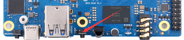

|
Note that the Linux desktop system will pop up the confirmation box shown in the figure below after pressing the buttons. You need to click the Shut Down option to shut down.  |
After shutting down, press the switch button on the development board to turn on.
Restart the command of the Linux system.
orangepi@orangepi:~$ sudo reboot
Ubuntu22.04 Gnome Wayland Desktop system instructions
|
ubuntu22.04 gnome image default pre -installed PanFork Mesa user space library, pre -installed Kodi player and Chromium browser support hard solution video. It should be noted that this image needs to be used under Wayland. If you need to use X11, select the XFCE type image. |
Ubuntu22.04 GNOME desktop system adaptation situation
| Function | Ubuntu22.04 Gnome Wayland |
| HDMI TX1video | OK |
| HDMI TX1 Audio | OK |
| HDMI TX2 video | OK |
| HDMI TX2 Audio | OK |
| HDMI RX video | OK |
| HDMI RX Audio | OK |
| USB2.0X2 | OK |
| USB3.0X2 | OK |
| 2.5G PCIe network port X2 | OK |
| 2.5G PCIe network port light | OK |
| Debug serial port | OK |
| RTC chip | OK |
| FAN Fan interface | OK |
| eMMC Extension ports | OK |
| AP6275P-WIFI | OK |
| AP6275P-BT | OK |
| AX200-WIFI | OK |
| AX200-BT | OK |
| AX210-WIFI | OK |
| AX210-BT | OK |
| RTL8852BE-WIFI | OK |
| RTL8852BE-BT | OK |
| MaskROM button | OK |
| Type-C to USB3.0 | OK |
| Type-C ADB Function | OK |
| Type-C DP video | OK |
| Type-C DP Audio | OK |
| Switch button | OK |
| Infrared function | OK |
| Three -color LED light | OK |
| MIC on board | OK |
| Headphones play | OK |
| Headset recording | OK |
| SPK trumpet | OK |
| 40PIN GPIO | OK |
| 40PIN I2C | OK |
| 40PIN SPI | OK |
| 40PIN UART | OK |
| 40PIN CAN | OK |
| 40PIN PWM | OK |
| TF card startup | OK |
| SPI+NVMe startup | OK |
| OV13850 Camera | OK |
| OV13855 Camera | OK |
| GPU | OK |
| VPU | OK |
| NPU | OK |
| REBOOT Command restart | OK |
| Poweroff Command shutdown | OK |
| MIPI LCD show | OK |
| MIPI LCD touch | OK |
| Watch Dog Test | OK |
| Chromium Hard solution video | OK |
| MPV Hard solution video | OK |
| Kodi Hard solution video | OK |
Confirm that the current window system used by the system is Wayland
The system used by the system default is Wayland, and the confirmation method is shown below:
First open the settings
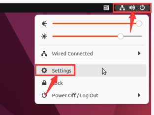
Then select about, if the Wayland description settings displayed by Windowing System in a column are correct
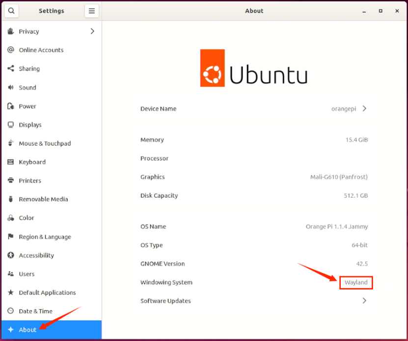
When the Log Out is out of the system, it will enter the login interface below
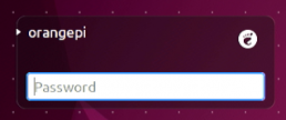
Please click the location shown below before logging in to the system again
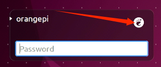
Then select Ubuntu on Wayland and enter the password login system
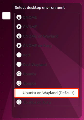


Switch the method of default audio equipment
Open the settings first
Then select Sound, and then select the audio device you want to use in Output Device
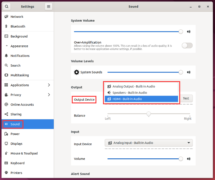

GPU test method
Open a terminal on the desktop, and then enter the glmark2 command. If you can see the Panfros after GL_VERDOR, This shows that it is used in GPU.
orangepi@orangepi:~$ glmark2
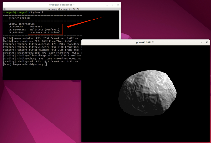
glmark2 running score test is generally more than 1,000 points
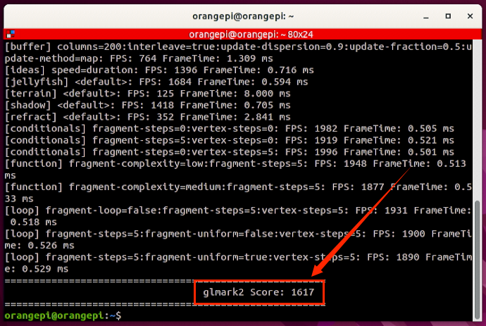
Run gpu_load.sh script to view the current load of the GPU
orangepi@orangepi:~$ gpu_load.sh
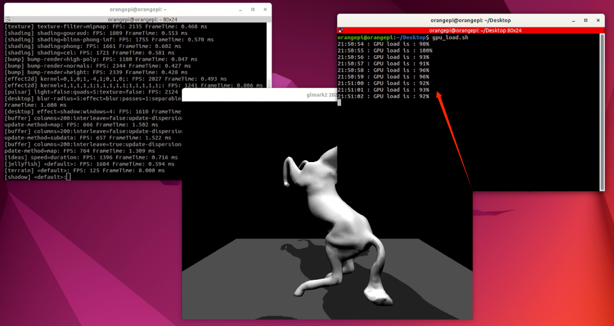


Chromium browser hard solution to play video test method
First open the chromium browser
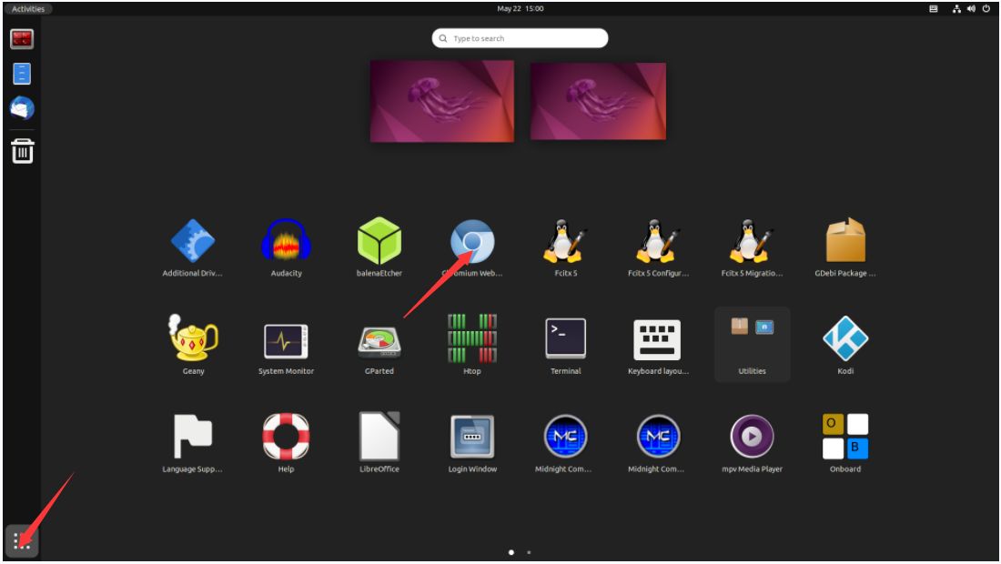
Then enter chrome://gpu in the Chromium browser to view the support of GPU and video decoding
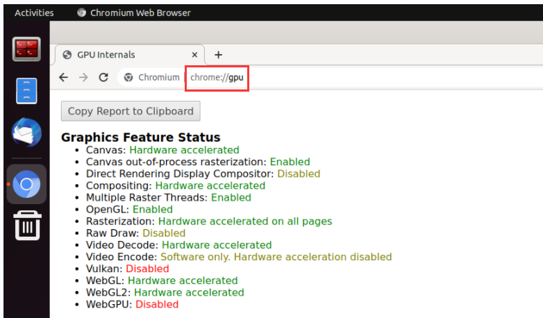
Then you can open a video website to play a video file, or enter the following path name player to play a test video file in the browser.
/usr/local/test.mp4
When playing the video, you can run the vpu_debug.sh script in the terminal. If there is a print output in the lower right corner of the figure below, it means that there is a hardware to decode the video.
orangepi@orangepi:~$ vpu_debug.sh
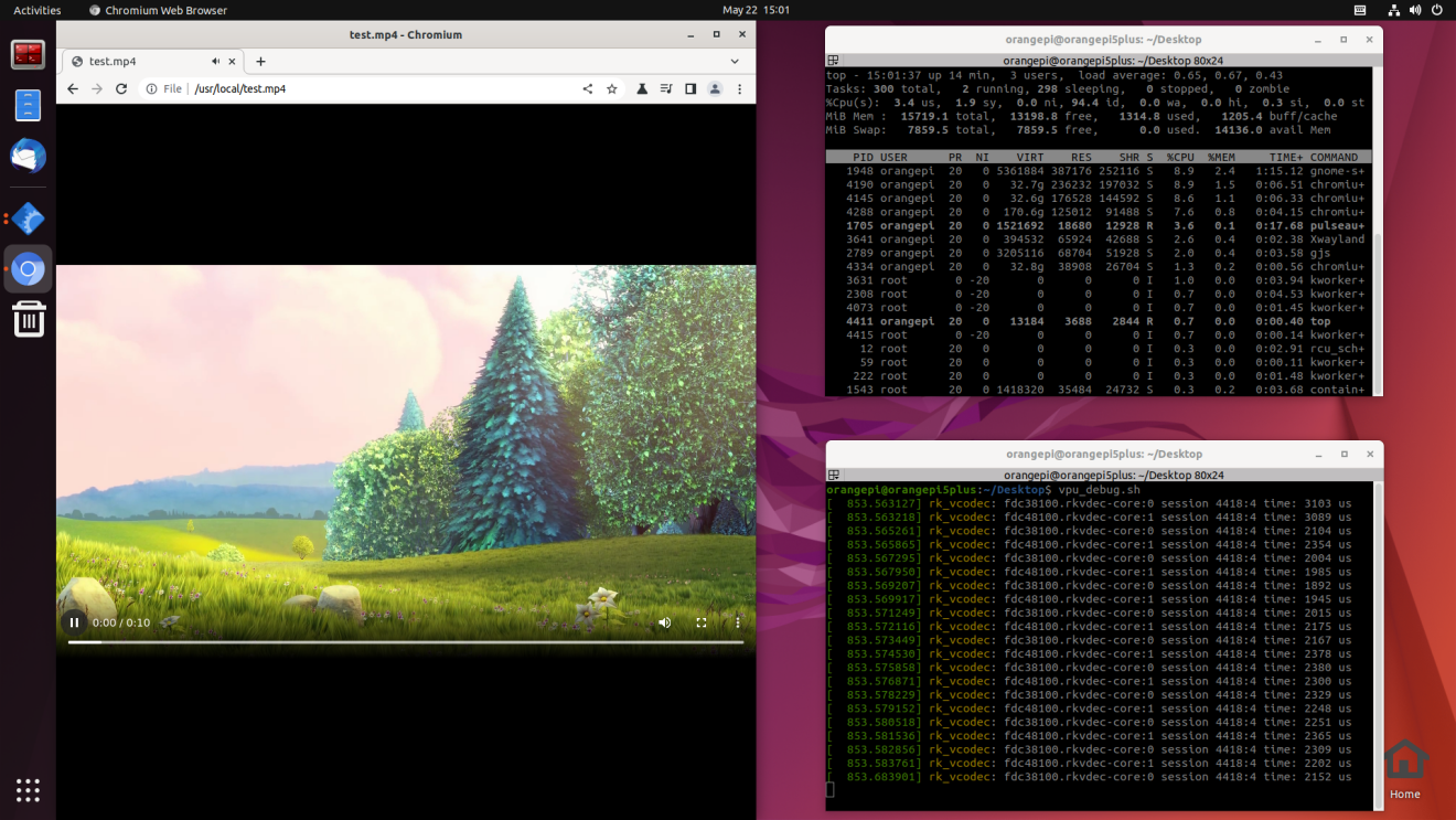


Kodi hard solution to play video test method
|
Note that there will be problems with the Kodi display directly on the Wayland desktop. Please open Kodi strictly according to the following method. |
First log in the system
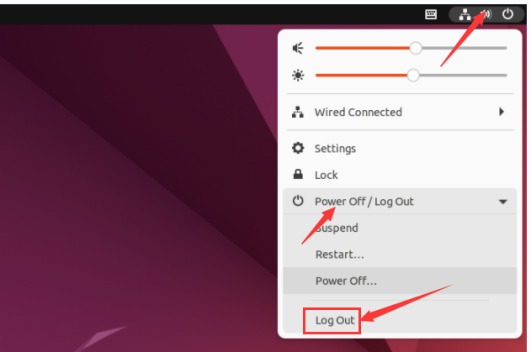
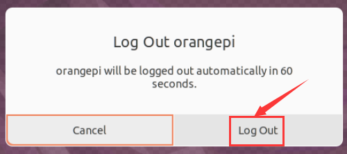
When the login system will enter the login interface below

Then click the location shown in the figure below
Then select Kodi Wayland, then enter the password login system
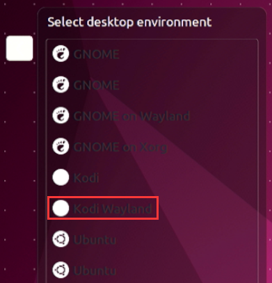
The interface after Kodi is opened is displayed as shown below
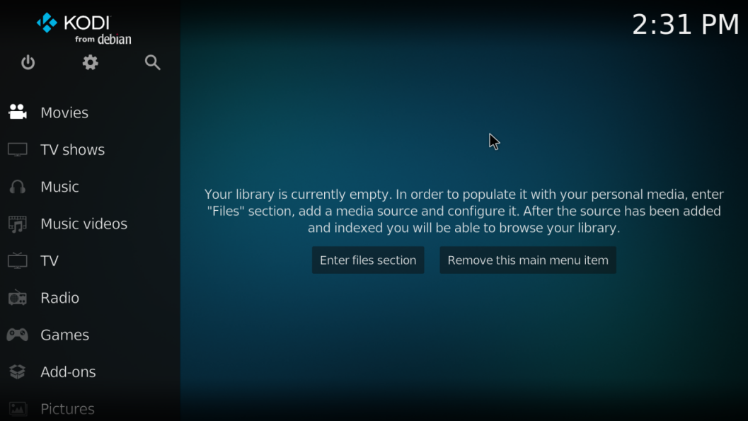
Then click Settings

Then select Player
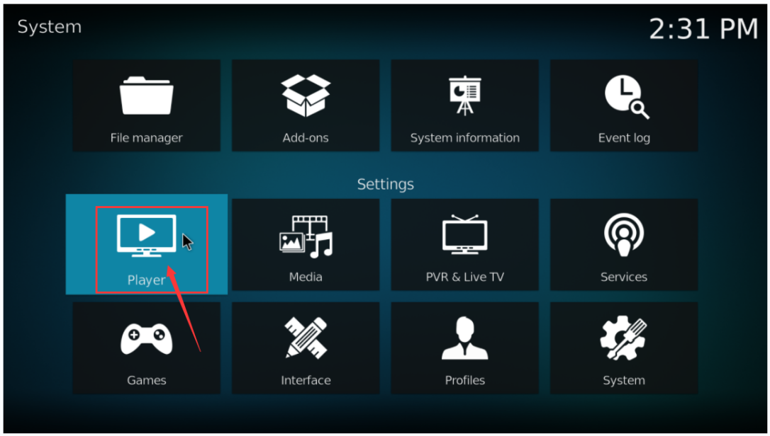
Then select Videos, and then click Standard in the lower left corner
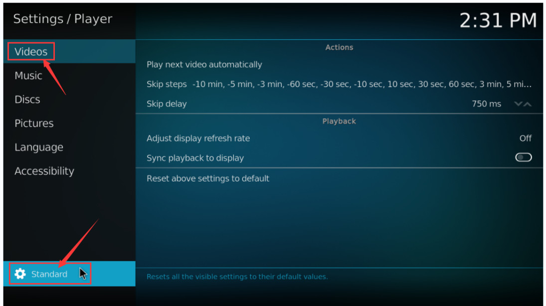
After clicking twice, it will be switched to the Expert mode. The specific display is shown in the figure below
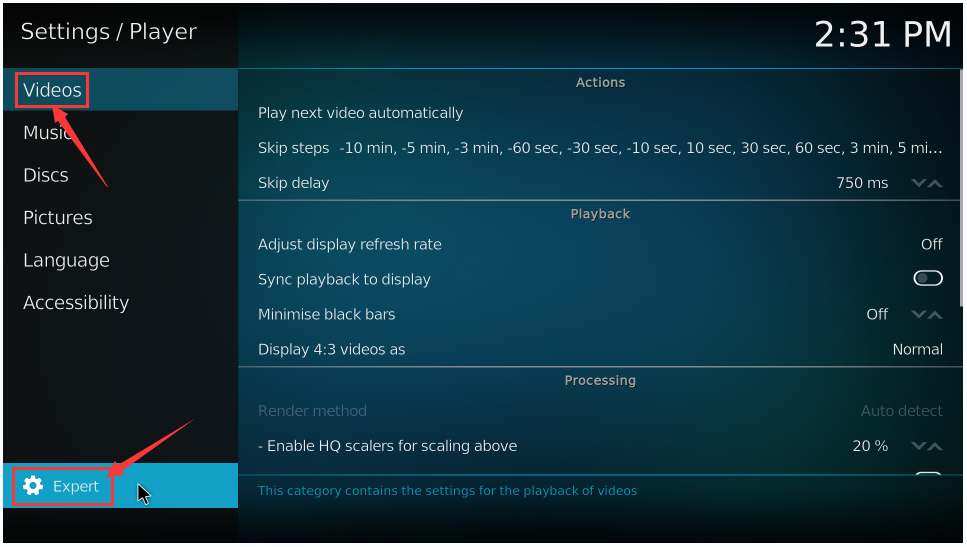
Then open the Allow using DRM PRIME decoder in the Processing settings
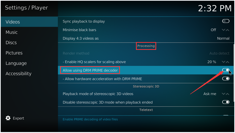
Then let's introduce a system's own test video test. You can also upload the video you want to play to the system, and then import and play
First enter the main interface, then select Movies
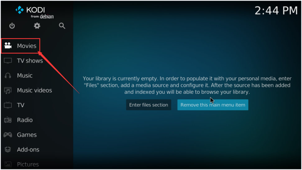
Then choose Add videos...
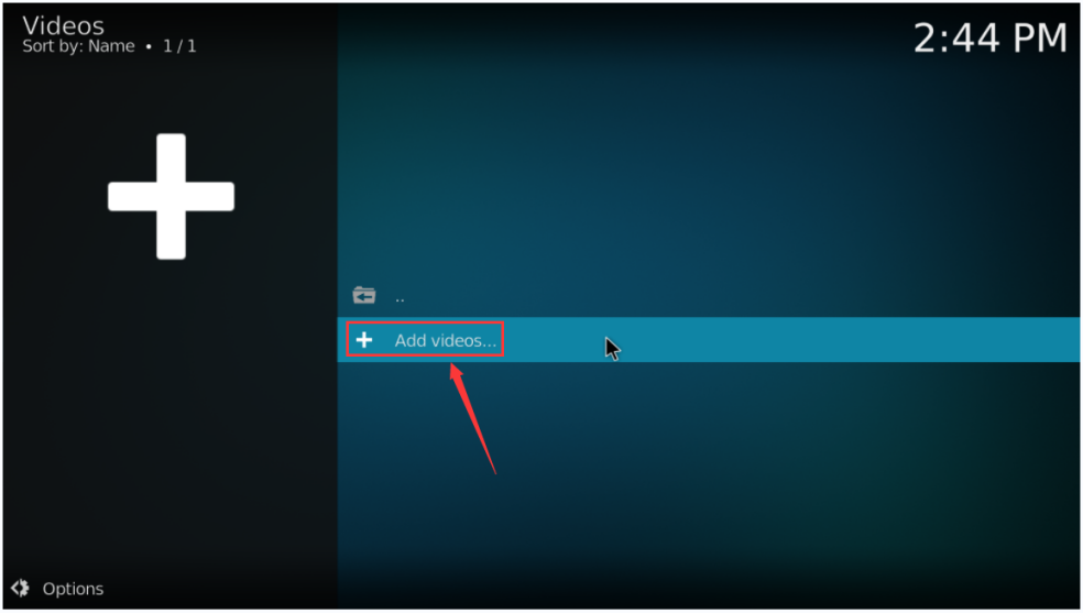
Then choose Browse
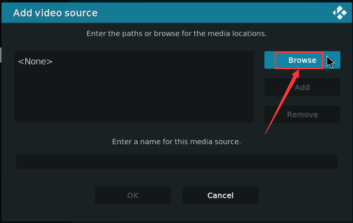
Then choose Root filesystem
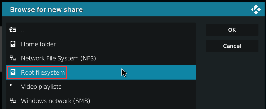
Then choose usr
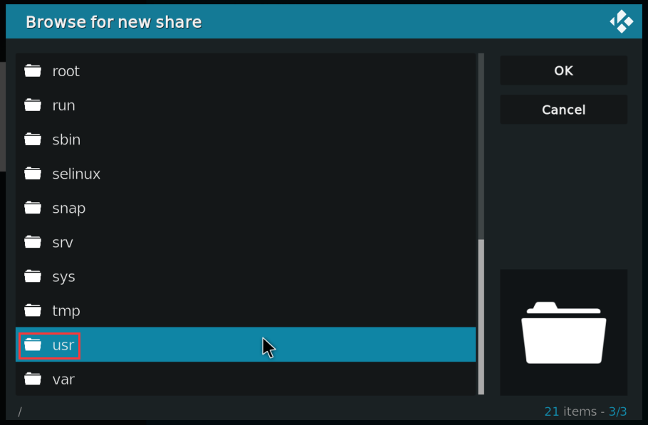
Then choose local
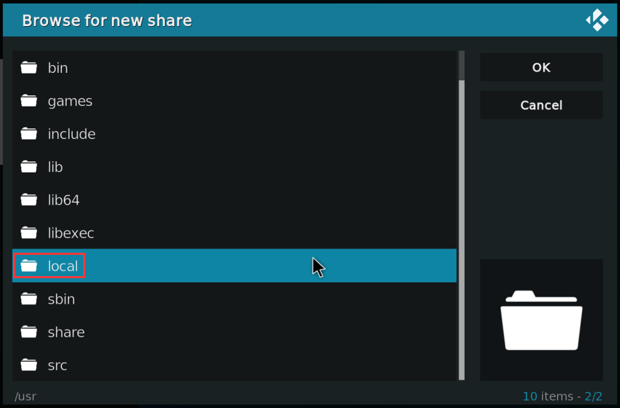
Then choose OK
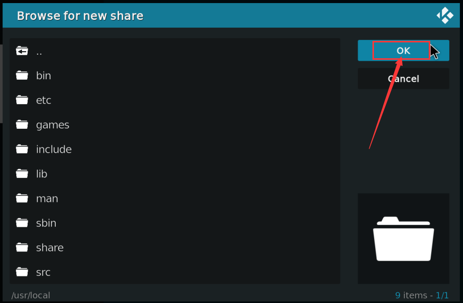
Then choose OK
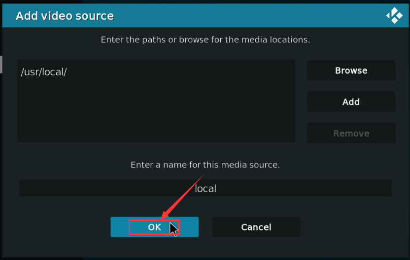
Then choose OK
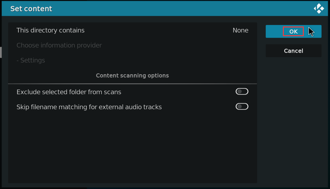
Then enter the Local folder
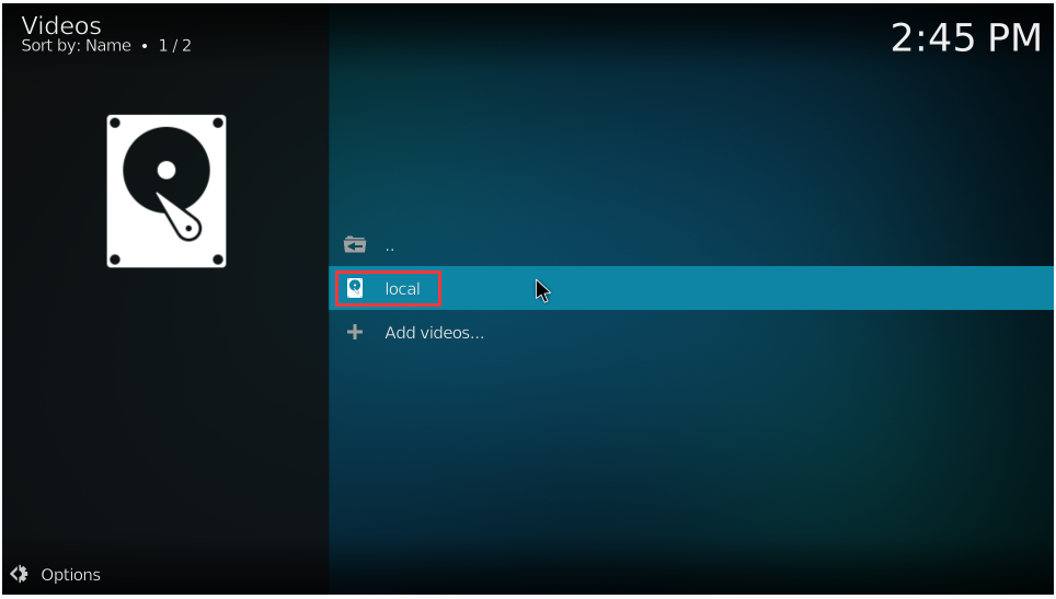
Then you can play test.mp4 test video
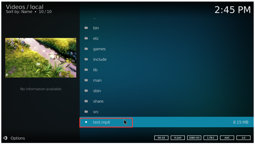
When playing the video, you can run the vpu_debug.sh script under the command line (via SSH or serial port). If there is a print output below, it means that there is a hardware to decode the video
orangepi@orangepi:~$ vpu_debug.sh
[ 1830.938378] rk_vcodec: fdc48100.rkvdec-core:1 session 3573:2 time: 2728 us
[ 1830.938461] rk_vcodec: fdc38100.rkvdec-core:0 session 3573:2 time: 2617 us
[ 1830.941179] rk_vcodec: fdc48100.rkvdec-core:1 session 3573:2 time: 2661 us
[ 1830.941777] rk_vcodec: fdc38100.rkvdec-core:0 session 3573:2 time: 2708 us
[ 1830.944727] rk_vcodec: fdc48100.rkvdec-core:1 session 3573:2 time: 3444 us
[ 1830.945211] rk_vcodec: fdc38100.rkvdec-core:0 session 3573:2 time: 3331 us
[ 1830.970563] rk_vcodec: fdc48100.rkvdec-core:1 session 3573:2 time: 2547 us
[ 1831.199650] rk_vcodec: fdc38100.rkvdec-core:0 session 3573:2 time: 2703 us
Play test.mp4 video file CPU occupation rates of about 20%~ 30%.
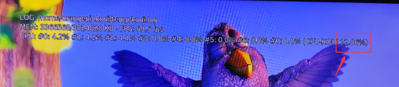


Ubuntu22.04 Gnome to install ROS 2 Humble
You can install ROS2 with install_ros.sh script
orangepi@orangepi:~$ install_ros.sh ros2
install_ros.sh script will automatically run the ros2 -h command after ros2 is installed. If you can see the printing below
usage: ros2 [-h] Call `ros2 <command> -h` for more detailed usage. ...
ros2 is an extensible command-line tool for ROS 2.
optional arguments:
-h, --help show this help message and exit
Commands:
action Various action related sub-commands
bag Various rosbag related sub-commands
component Various component related sub-commands
daemon Various daemon related sub-commands
doctor Check ROS setup and other potential issues
interface Show information about ROS interfaces
launch Run a launch file
lifecycle Various lifecycle related sub-commands
multicast Various multicast related sub-commands
node Various node related sub-commands
param Various param related sub-commands
pkg Various package related sub-commands
run Run a package specific executable
security Various security related sub-commands
service Various service related sub-commands
topic Various topic related sub-commands
wtf Use `wtf` as alias to `doctor`
Call `ros2 <command> -h` for more detailed usage.
Then you can use the test_ros.sh script to test whether the ROS 2 is successfully installed. If you can see the printing below, it means that the ROS 2 can run normally
orangepi@orangepi5plus:~$ test_ros.sh
[INFO] [1671174101.200091527] [talker]: Publishing: 'Hello World: 1'
[INFO] [1671174101.235661048] [listener]: I heard: [Hello World: 1]
[INFO] [1671174102.199572327] [talker]: Publishing: 'Hello World: 2'
[INFO] [1671174102.204196299] [listener]: I heard: [Hello World: 2]
[INFO] [1671174103.199580322] [talker]: Publishing: 'Hello World: 3'
[INFO] [1671174103.204019965] [listener]: I heard: [Hello World: 3]
Run the following command to open rviz2
orangepi@orangepi:~$ source /opt/ros/humble/setup.bash
orangepi@orangepi:~$ ros2 run rviz2 rviz2
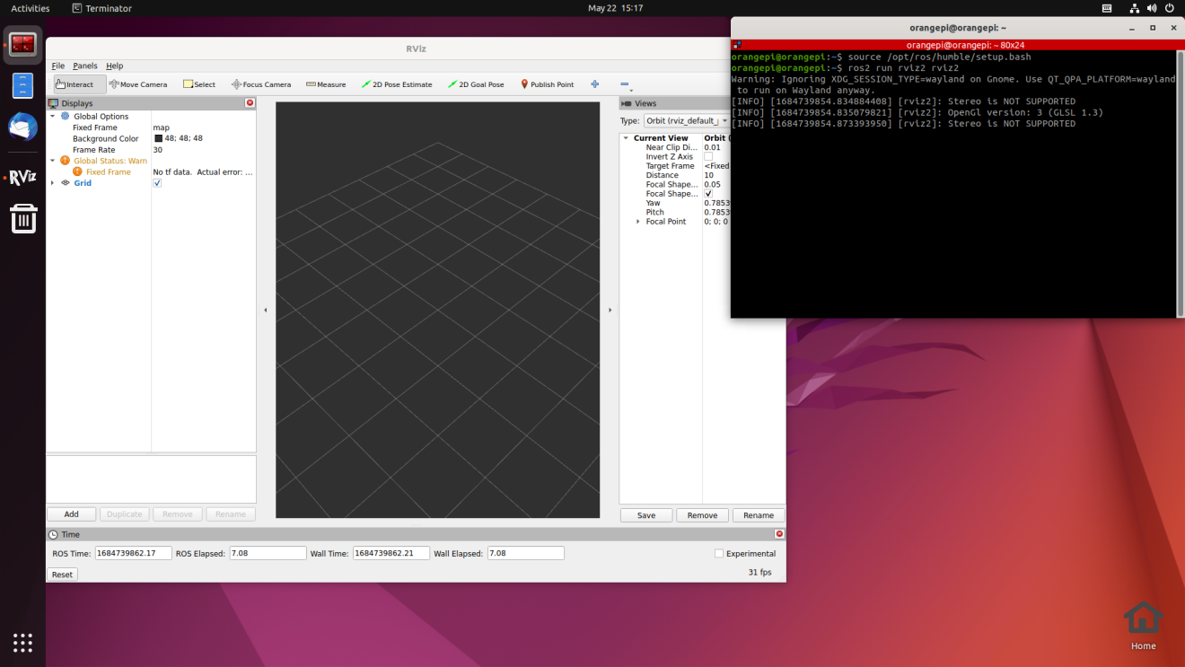
Reference document
http://docs.ros.org/en/humble/index.html
http://docs.ros.org/en/humble/Installation/Ubuntu-Install-Debians.html

Set the Chinese environment and the method of installing the Chinese input method
Open the settings first
Then find the Region & Language option, and then click Manage Installed Languages options
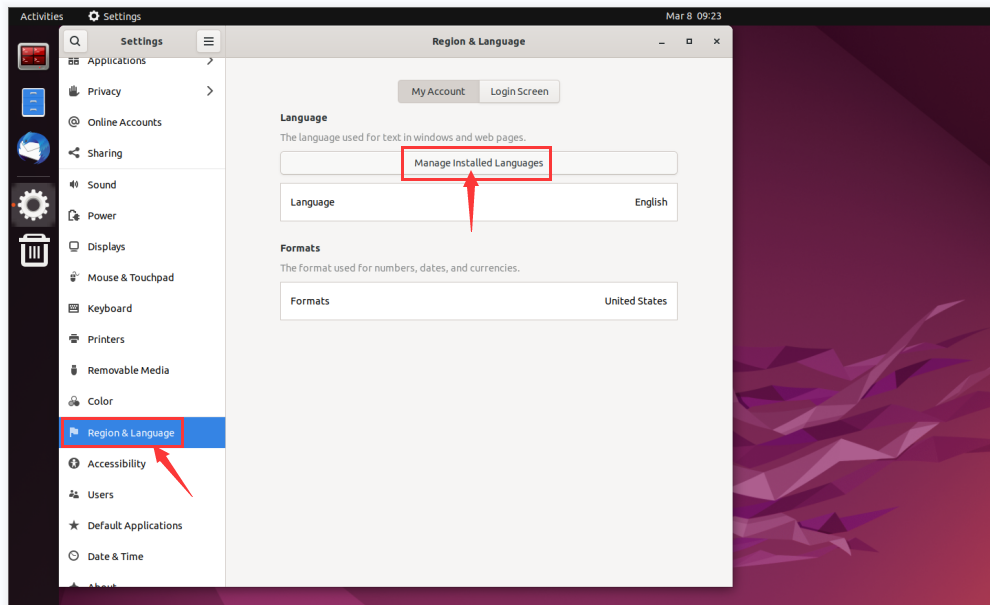
Then use the left mouse button to select Chinese (China) and hold it down, and then drag it up to the beginning. The display after the dragging is shown in the figure below:
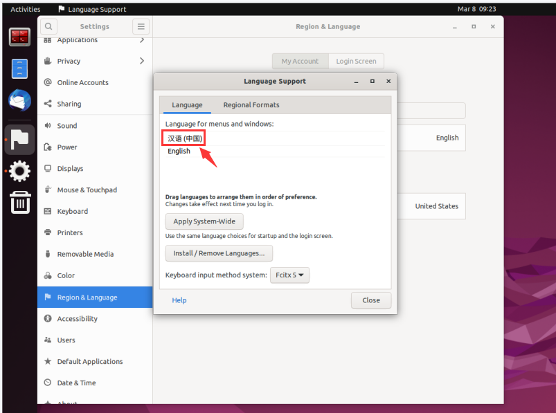
Then select the Apply System-Wide to apply the Chinese settings to the entire system
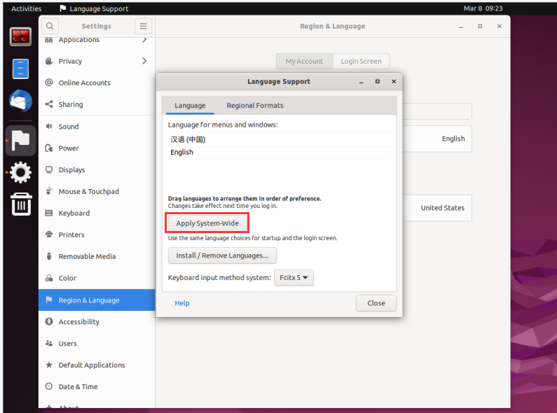
Then restart the linux system to make the configuration effective
After re -entering the system, please choose not to ask me again at the interface below, and then determine whether the standard folder should be updated to Chinese according to your preference
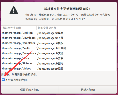
Then you can see that the desktop is displayed as Chinese
Then open the Fcitx5 configuration program
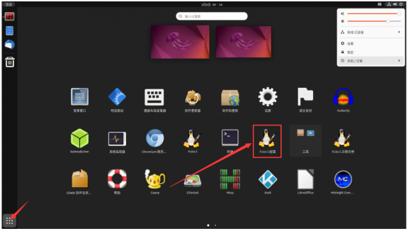
Then choose to use Pinyin input method
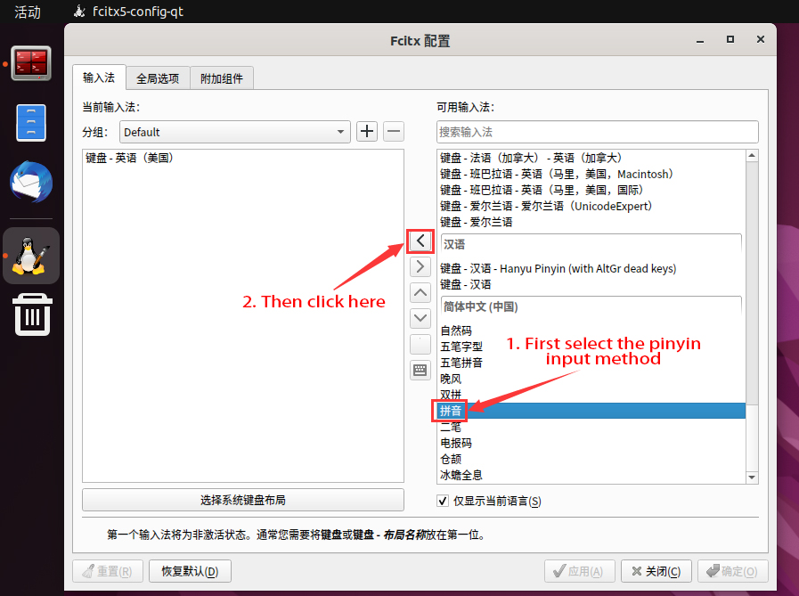
The interface after selecting is shown below, then click OK
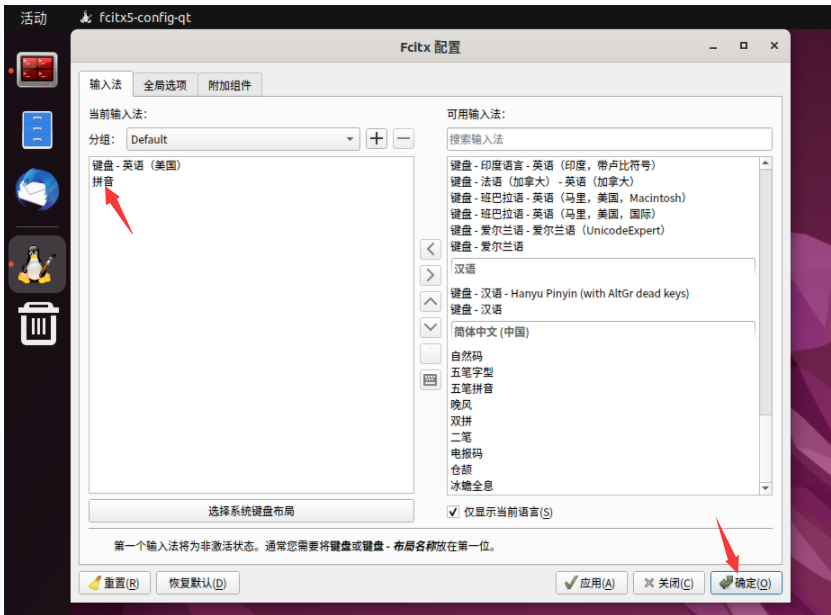
Then we can open the Chinese input method of Geany test, and the way to open is shown in the figure below
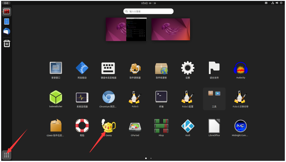
After opening Geany, the default is an English input method. We can switch into Chinese input method through the Ctrl+Space shortcut keys, and then we can enter Chinese
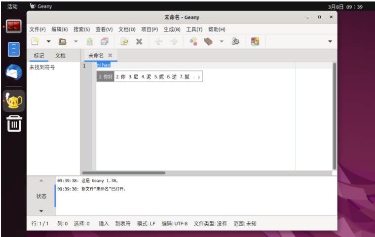


Orange Pi OS Arch system use instructions
Orange Pi OS Arch system adaptation situation
| Function | OPi OS Arch Gnome | OPi OS Arch Xfce(To be released) |
| HDMI TX1 video | OK | OK |
| HDMI TX1 Audio | OK | OK |
| HDMI TX2 video | OK | OK |
| HDMI TX2 Audio | OK | OK |
| HDMI RX video | OK | OK |
| HDMI RX Audio | OK | OK |
| USB2.0X2 | OK | OK |
| USB3.0X2 | OK | OK |
| 2.5G PCIe network port X2 | OK | OK |
| 2.5G PCIe network portlight | OK | OK |
| Debug serial port | OK | OK |
| RTC chip | OK | OK |
| FAN Fan interface | OK | OK |
| eMMC Extension ports | OK | OK |
| AP6275P-WIFI | OK | OK |
| AP6275P-BT | OK | OK |
| AX200-WIFI | OK | OK |
| AX200-BT | OK | OK |
| AX210-WIFI | OK | OK |
| AX210-BT | OK | OK |
| RTL8852BE-WIFI | OK | OK |
| RTL8852BE-BT | OK | OK |
| MaskROM button | OK | OK |
| Type-C to USB3.0 | OK | OK |
| Type-C DP video | OK | OK |
| Type-C DP Audio | OK | OK |
| Switch button | OK | OK |
| Infrared function | OK | OK |
| Three -color LED light | OK | OK |
| Board MIC | OK | OK |
| Headphones play | OK | OK |
| Headset recording | OK | OK |
| SPK trumpet | OK | OK |
| 40PIN GPIO | OK | OK |
| 40PIN I2C | OK | OK |
| 40PIN SPI | OK | OK |
| 40PIN UART | OK | OK |
| 40PIN CAN | OK | OK |
| 40PIN PWM | OK | OK |
| TF card startup | OK | OK |
| SPI+NVME start up | OK | OK |
| OV13850 Camera | OK | OK |
| OV13855 Camera | OK | OK |
| GPU | OK | OK |
| VPU | OK | OK |
| NPU | NO | NO |
| REBOOT Command restart | OK | OK |
| Poweroff Command shutdown | OK | OK |
| MIPI LCD show | OK | OK |
| MIPI LCD touch | OK | OK |
| Watch Dog Test | OK | OK |
| Chromium Hard solution video | NO | NO |
| MPV Hard solution video | OK | OK |
How to use the M.2 E-Key PCIE WIFI6+Bluetooth module
- First of all, you need to buy a PCIE WIFI6+Bluetooth module
Serial number model Physical picture Supportive OS 1 AX200 (PCIE+USB Port)
Debian Ubuntu
OpenWRT
OPi OS Arch
2 AX210 (PCIE+USB Port)
Debian Ubuntu
OpenWRT
OPi OS Arch
3 RTL8852BE (PCIE+USB Port)
Debian Ubuntu
Android12
OPi OS Arch
OPi OS Droid
Pay attention to RTL8852BE, please do not buy the module shown in the figure below, there will be problems after testing.


Then insert the WiFi module into the M.2 E-Key interface of the development board and fix it
If everything is normal after the system starts, use the following command to see the WIFI device nodea
[orangepi@orangepi ~]$ ip a
......
4: wlan0: <BROADCAST,MULTICAST,UP,LOWER_UP> mtu 1500 qdisc noqueue state UP group default qlen 1000
- link/ether 38:7a:0e:e3:80:05 brd ff:ff:ff:ff:ff:ff
- inet 192.168.1.237/24 brd 192.168.1.255 scope global dynamic noprefixroute wlan0
- valid_lft 42938sec preferred_lft 42938sec
- inet6 fe80::a098:5942:16e:e817/64 scope link noprefixroute
- valid_lft forever preferred_lft forever
The steps connected to the wifi are shown below:
First click the area in the upper right corner of the desktop

Then choose Wi-Fi
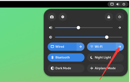
Then select the WIFI you want to connect

Then enter the password of the wifi, and click Connect
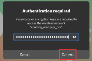
Then enter the following interface to see the wifi connection
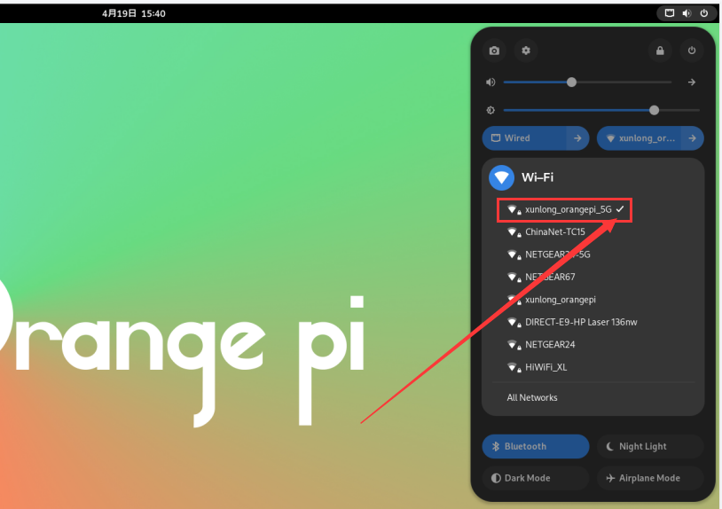
Example of Bluetooth use:
First click the area in the upper right corner of the desktop
Then open the settings
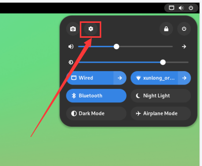
Then select Bluetooth in the settings, and make sure that the switch button in the upper right corner of the Bluetooth is opened
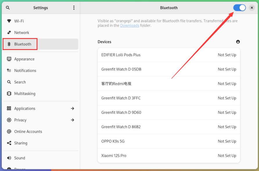
Then choose the Bluetooth device you want to configure the right, such as pairing with Android phones
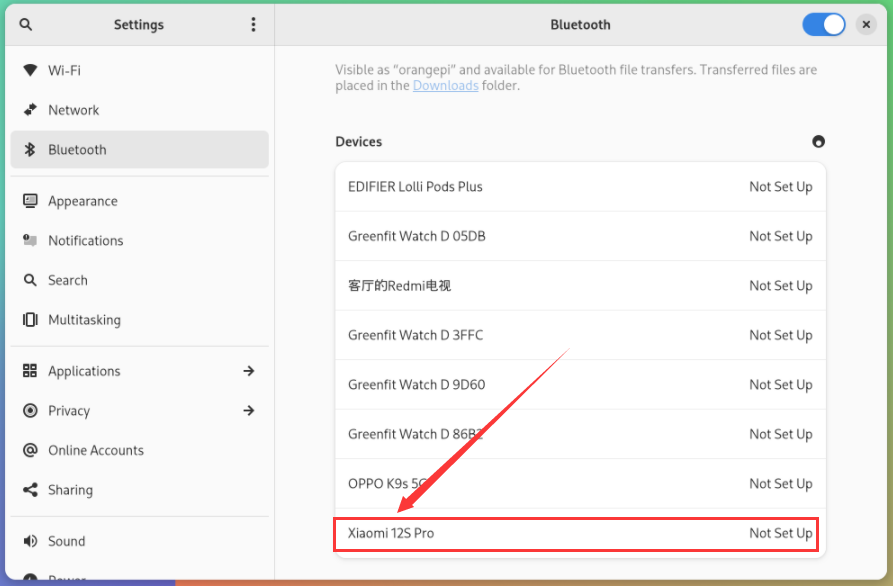
Then click Confirm, the mobile phone also needs to confirm the pairing
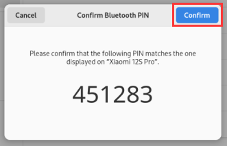
The display of the Bluetooth and Android phone is shown below:
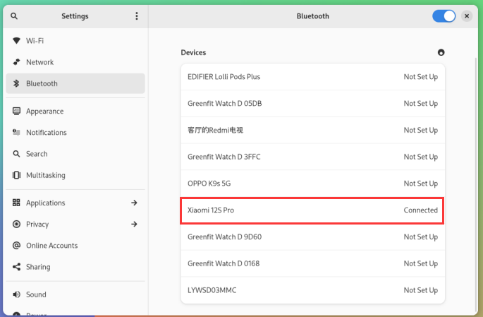
Then click the paired Bluetooth device to pop up the operating interface shown in the figure below
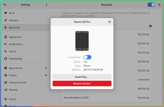
Click Send Files... you can send a file to the phone
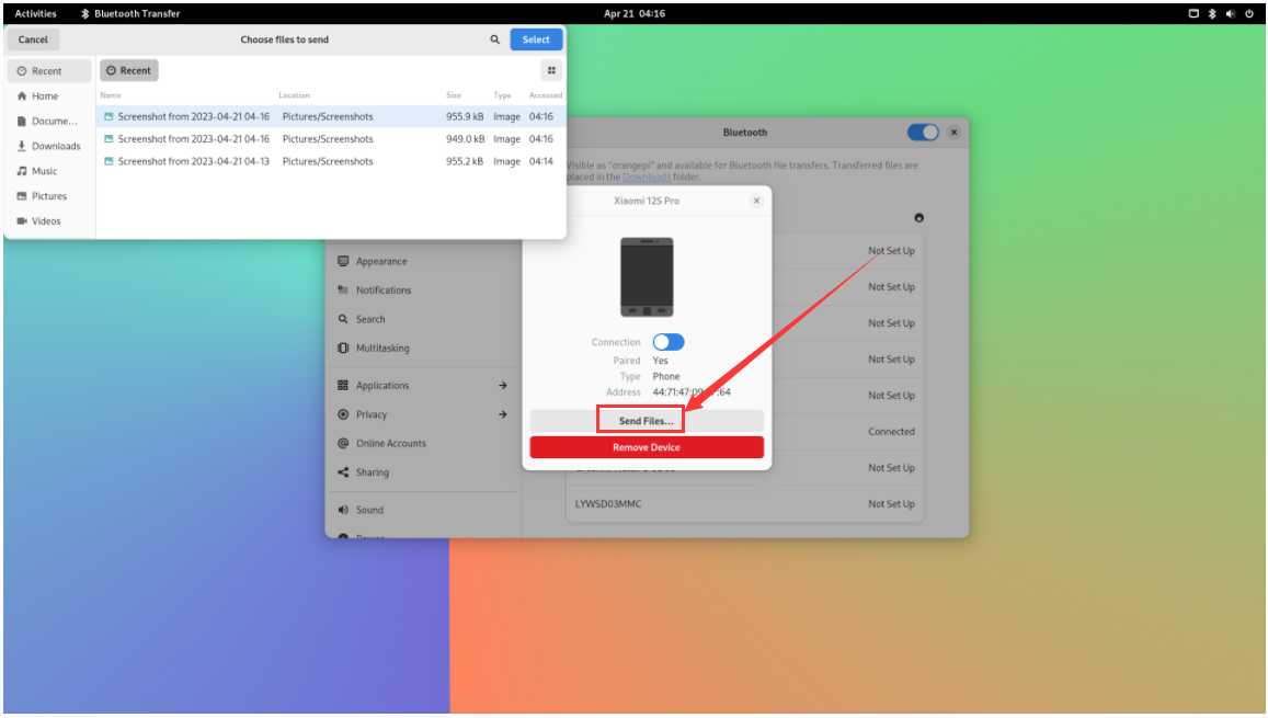
The schematic diagram of the Bluetooth sent pictures to the phone is shown below:
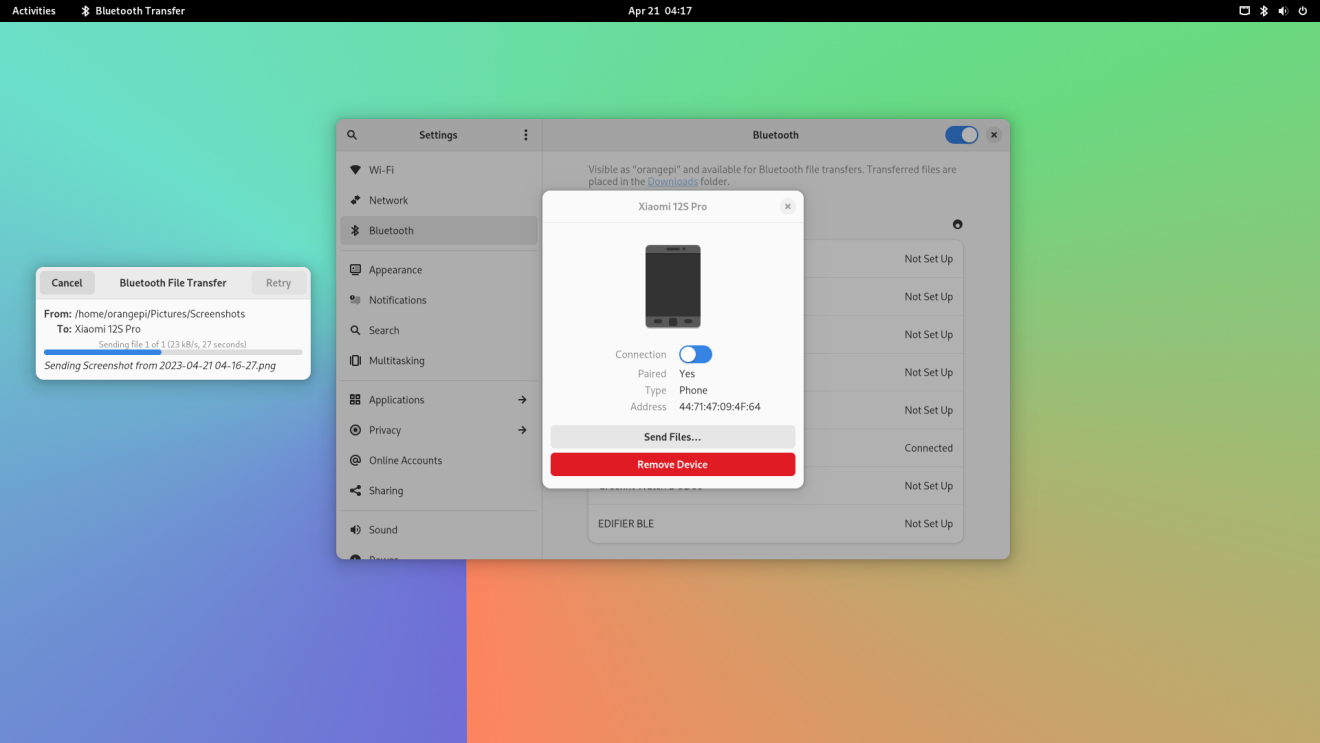


How to use 10.1 inch MIPI LCD screen
10.1 -inch MIPI screen assembly method
First prepare the required accessories
10.1 -inch MIPI LCD display+touch screen (common to OPI5/OPI5B)
Screen divert+31pin to 40pin exhaust
30pin mipi line
12pin touch screen line
According to the figure below, the 12PIN touch screen row, 31PIN to 40Pin line, and 30Pin MIPI cables get on the screen dial board. Pay attention to the blue insulation of the touch screen row line face to down. If an error is connected, it will cause no display or unable to touch..
Place the connected rotor connected to the puzzle on the MIPI LCD screen according to the figure below, and connect the MIPI LCD screen and the rotary board through 31PIN to 40Pin row
Then connect the touch screen and the rotor board through the 12PIN touch screen line, pay attention to the orientation of the insulating surface
Finally connect to the LCD interface of the development board through the 30PIN MIPI duct.
Note that the touch interface below is not used for the LCD MIPI screen. It is currently a spare interface and cannot be used.
How to open 10.1 -inch MIPI LCD screen configuration
The position of the interface of the MIPI LCD screen on the development board is shown in the figure below
OPi OS Arch image default is not to open the mipi lcd screen configuration. If you need to use the mipi lcd screen, you need to open it manually. The method of opening the mipi lcd configuration is shown below:
First add the following configuration in/boot/extlinux/extlinux.conf
[orangepi@orangepi ~]$ sudo vim /boot/extlinux/extlinux.conf
LABEL Orange Pi
LINUX /Image
FDT /dtbs/rockchip/rk3588-orangepi-5-plus.dtb
FDTOVERLAYS /dtbs/rockchip/overlay/rk3588-opi5plus-lcd.dtbo #The configuration that needs to be added
Then restart the OPi OS Arch system
After restarting, you can see the display of the LCD screen as shown below (default vertical screen):

Method of rotating display and touch direction
First click the area in the upper right corner of the desktop
Then open the settings
Then choose Displays
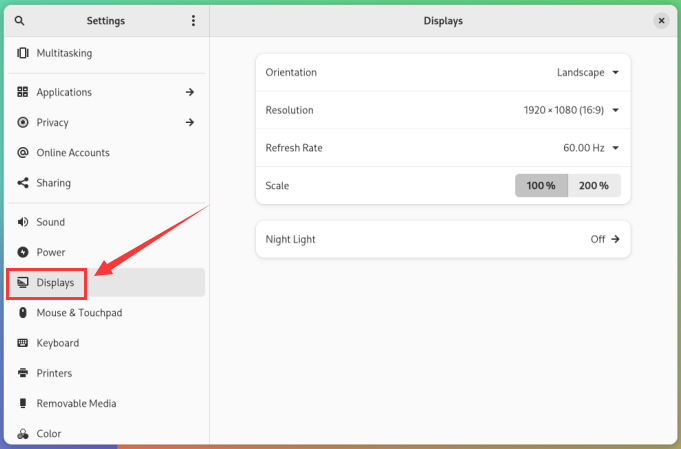
Then select the direction you want to rotate in the Orientation of Displays
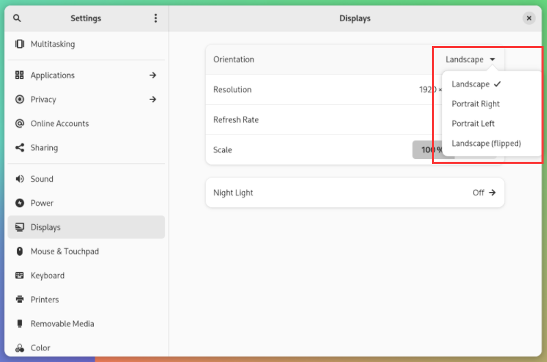
Then choose Apply
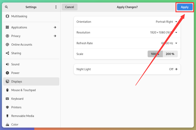
Then you can see that the screen has been rotated. At this time, you need to choose Keep Changes to determine the rotation
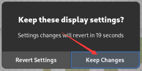
The display of the LCD screen after 90 degrees is shown below:
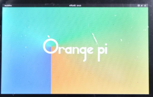
The touch function of the OPi OS Arch system LCD screen will rotate with the rotation of the display direction without other settings.


OV13850 and OV13855 MIPI test methods for testing
At present, the development board supports two MIPI cameras, OV13850 and OV13855. The specific pictures are shown below:
OV13850 camera of 13 million MIPI interface
13 million MIPI interface OV13855 camera
The rotary board used by OV13850 and OV13855 cameras is the same as the FPC cable, but the two cameras are different from the position on the rotary board. The FPC lines are shown in the figure below. Please note that the FPC line is directed. It is marked that the TO MB must be inserted into the camera interface of the development board. It is marked that the end of TO CAMERA needs to be inserted on the camera transfer board
There are a total of 3 cameras on the camera to connect to the board, which can only be used at the same time, as shown in the figure below, of which:
No. 1 interface is connected to the OV13850 camera
No. 2 interface connected OV13855 camera
No. 3 interface is not used, just ignore it.

Orange Pi 5 Plus development board has a total of 1 camera interface, which is shown below:
The method of the camera inserted on the development board interface is shown below:
After connecting the camera to the development board, we can use the following method to test the next camera:
First add the following configuration in /boot/extlinux/extlinux.conf
[orangepi@orangepi ~]$ sudo vim /boot/extlinux/extlinux.conf
LABEL Orange Pi
LINUX /Image
FDT /dtbs/rockchip/rk3588-orangepi-5-plus.dtb
FDTOVERLAYS /dtbs/rockchip/overlay/rk3588-opi5plus-ov13850.dtbo
The red font demonstrates the configuration of the camera interface ov13850. The other configurations are shown in the table below, and the corresponding DTBO configuration can be added behind FDTOVERLAYS.
| Camera | Dtbo configuration |
| connect ov13850 | /dtbs/rockchip/overlay/rk3588-opi5plus-ov13850.dtbo |
| connect ov13855 | /dtbs/rockchip/overlay/rk3588-opi5plus-ov13855.dtbo |
Then restart the OPi OS Arch system
Then open a terminal in the desktop system and run the script below
orangepi@orangepi:~$ test_camera.sh
Then you can see the preview of the camera
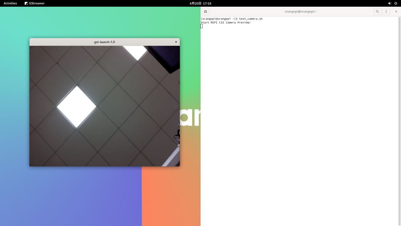

Set the Chinese environment and the method of installing the Chinese input method
First click the area in the upper right corner of the desktop
Then open the settings
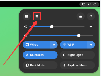
Then find the Region & Language option
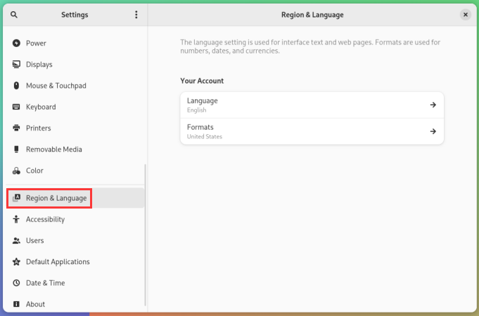
Then choose Language
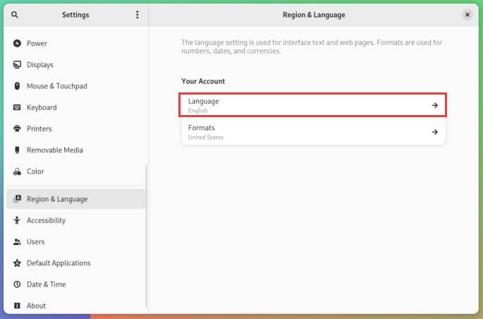
Then select Chinese
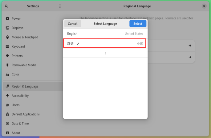
then click Select
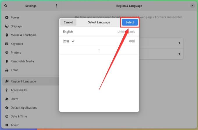
Then click Logout... log in to the system, and then log in to the system
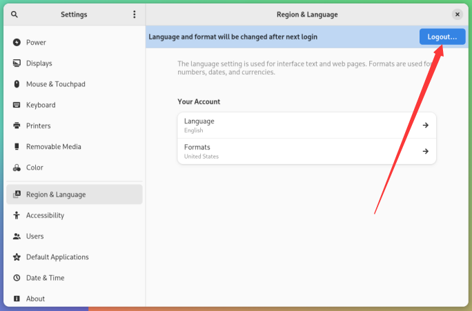
Then you can see that the desktop is displayed as Chinese
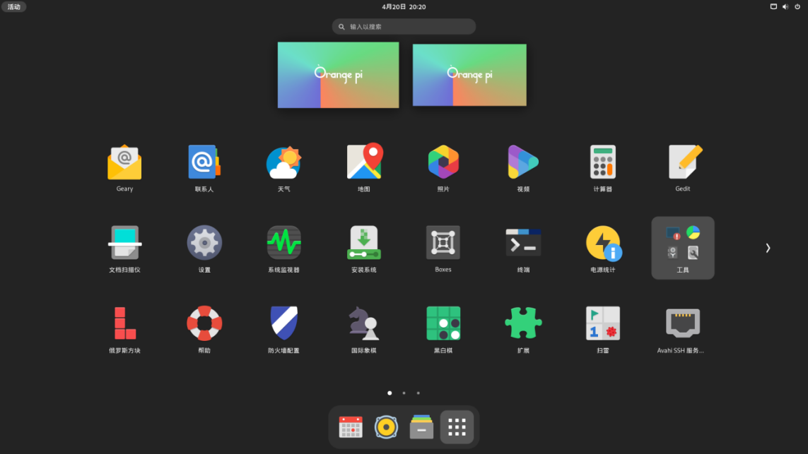
Then install fcitx-im and fcitx-configtool
[orangepi@orangepi ~]$ sudo pacman -S fcitx-im fcitx-configtool
:: There are 3 members in the group fcitx-im:
:: Software warehouse Community
1) fcitx 2) fcitx-qt5 3) fcitx-qt6
Enter a selection (default = all selected): 1
Then open the Fcitx configuration program
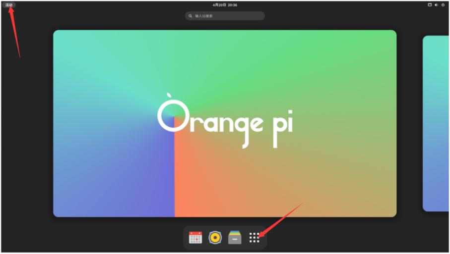
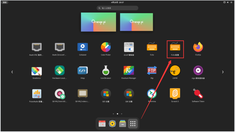
Then add Google Pinyin input method
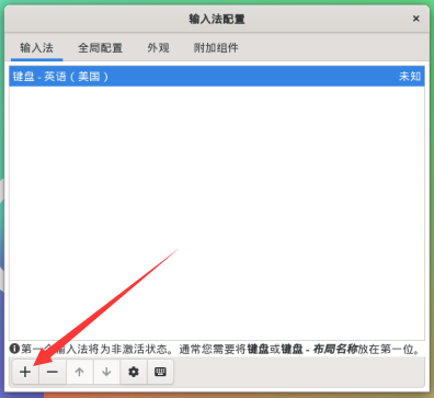
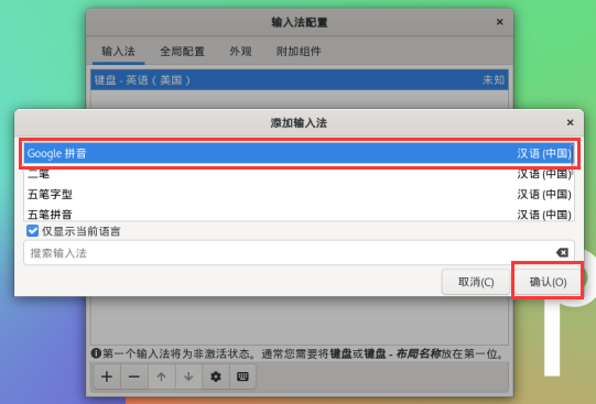
Then we can open a terminal test in the Chinese input method. After opening the terminal, if the English input method is still in English, we can switch to the Chinese input method through the Ctrl+Space shortcut keys, and then you can enter Chinese
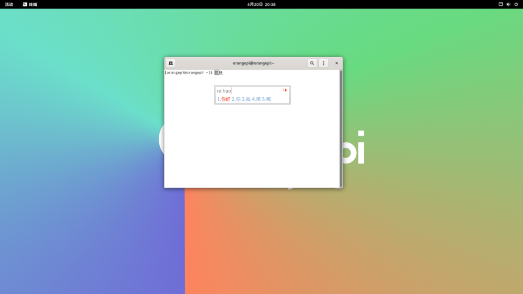


HDMI IN test method
The position of the development board HDMI In interface is shown below:
First use the HDMI to HDMI line shown below to output the HDMI output of other devices to the HDMI In interface of the development board
The OPi OS Arch system HDMI in function is closed by default, and the opening method is shown below:
First add the following configuration in /boot/extlinux/extlinux.conf
[orangepi@orangepi ~]$ sudo vim /boot/extlinux/extlinux.conf
LABEL Orange Pi
LINUX /Image
FDT /dtbs/rockchip/rk3588-orangepi-5-plus.dtb
FDTOVERLAYS /dtbs/rockchip/overlay/rk3588-hdmirx.dtbo #The configuration that needs to be added
Then restart the OPi OS Arch system
After restarting into the system, open a terminal on the desktop, and then run the test_hdmiin.sh script
[orangepi@orangepi ~]$ test_hdmiin.sh
Then you can see the input screen of the HDMI in (the HDMI in in the figure below shows the screen of the OPI5 development board HDMI output, and it is playing a video at this time). test_hdmiin.sh script defaults to the audio entered by HDMI in to the HDMI_TX1, HDMI_TX2 and ES8388 (representing speakers or headphones) of the development board.
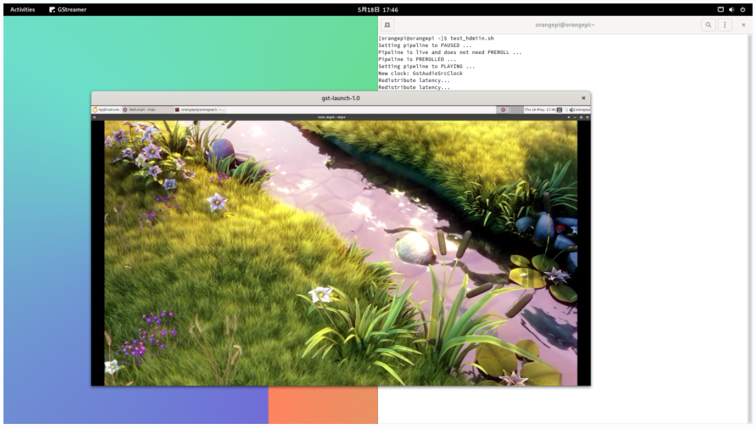
In addition to testing HDMI IN using test_hdmiin.sh, we can also use Qt V4L2 test Utility to test HDMI in video (this method cannot test audio at present). The detailed steps are shown below:
Enter the application list first
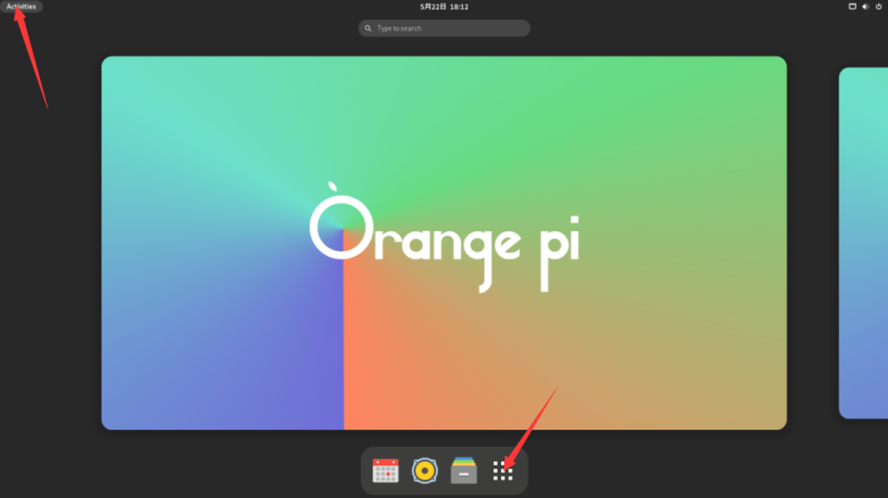
Then find Qt V4L2 test Utility and open it
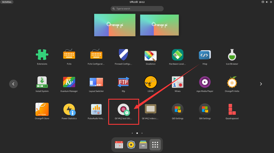
Then make sure Qt V4L2 test Utility recognizes the HDMI In device
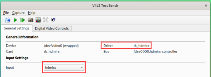
Then click the location shown in the figure below to see the video entered by HDMI In
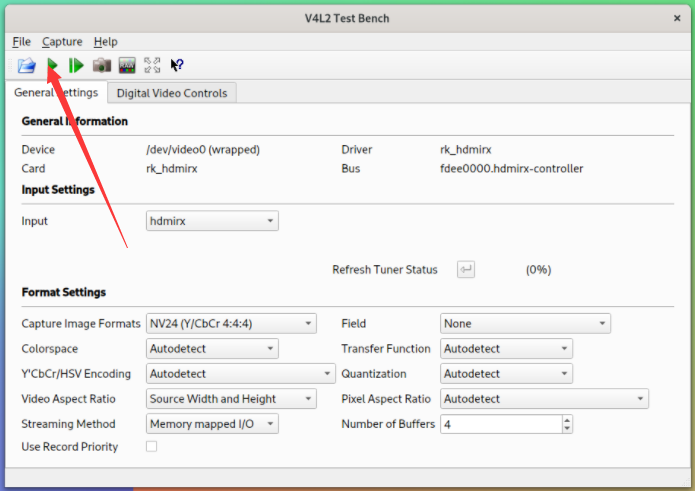
The video window entered by HDMI In is shown below:
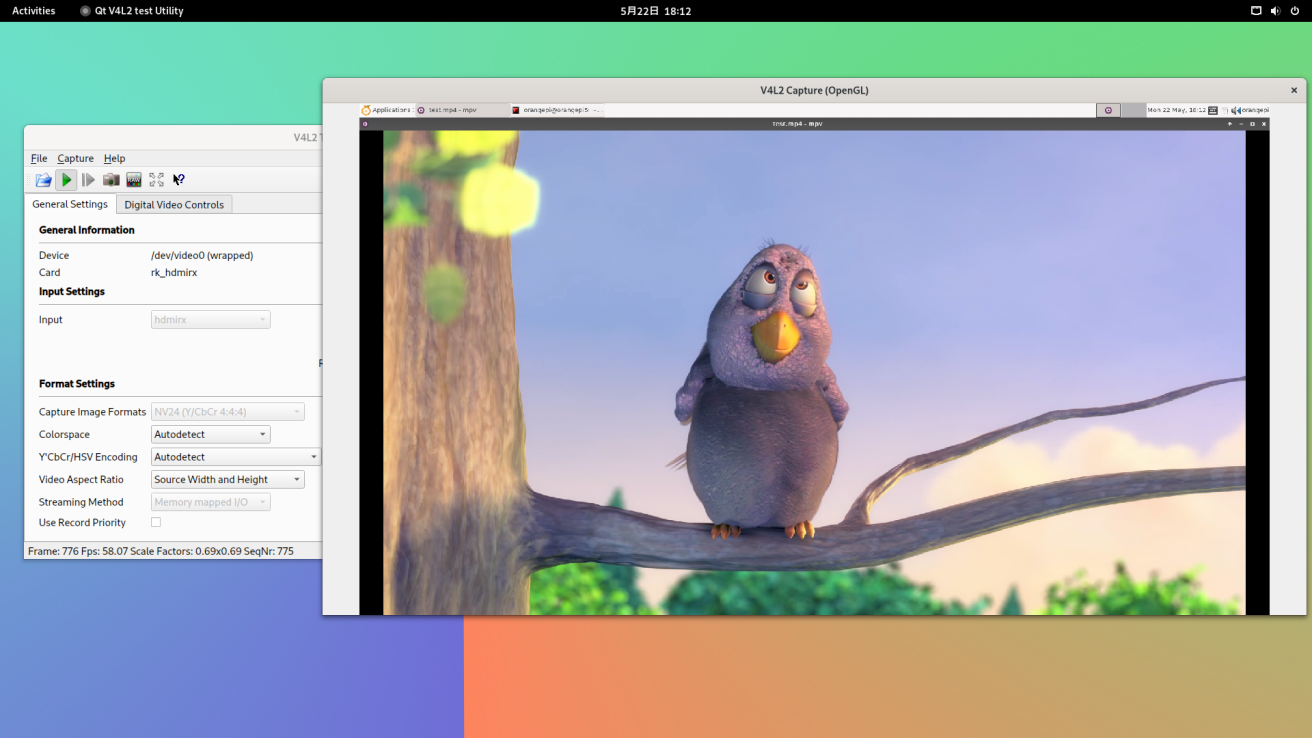


How to install wiringOP
|
Note that Wiringop has been pre -installed in the OPI OS Arch image released by Orange PI. Unless Wiringop's code is updated, it is not necessary to re -download and compile and install it,just use it directly. After entering the system, you can run the gpio readall command. If you can see the output below, it means that wiringOP is pre -installed and can be used normally
wiringOP is currently adapted to set the GPIO port input output, set the GPIO port output high and low level, and set the function of pulling and down resistance. It is impossible to use functions like hardware PWM. |

Download the code of wiringOP
[orangepi@orangepi ~]$ sudo pacman -Syy git
[orangepi@orangepi ~]$ git clone https://github.com/orangepi-xunlong/wiringOP.git -b next
Note that Orange Pi 5 Plus needs to download the code of the wiringOP next branch, please don't miss the parameter of -b next.
If you have a problem with the download code from github, you can download the source code compression package of wiringOp.tar.gz in the official tools of the Orange Pi 5 Plus data download page
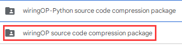
Compile and install wiringOP
[orangepi@orangepi ~]$ sudo pacman -Syy make gcc
[orangepi@orangepi ~]$ cd wiringOP
[orangepi@orangepi wiringOP]$ sudo ./build clean
[orangepi@orangepi wiringOP]$ sudo ./build
Test the output of the GPIO Readall command as follows
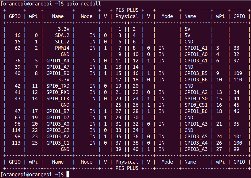

40 PIN interface GPIO, I2C, UART, SPI, CAN and PWM test
|
Note that if you need to set FDT Overlays to open multiple configurations at the same time, please use a space to write in a line like the red font configuration below. [orangepi@orangepi ~]$ sudo vim /boot/extlinux/extlinux.conf LABEL Orange Pi LINUX /Image FDT /dtbs/rockchip/rk3588s-orangepi-5.dtb FDTOVERLAYS /dtbs/rockchip/overlay/rk3588-i2c1-m2.dtbo /dtbs/rockchip/overlay/rk3588-uart0-m2.dtbo |
40 PIN GPIO port test
A total of 28 GPIO ports can be used in the development board 40 PIN. Below is No. 7 pins -corresponding to GPIO1_D6 -corresponding WPI serial number 2 -as an example to demonstrate how to set the high and low level of the GPIO port
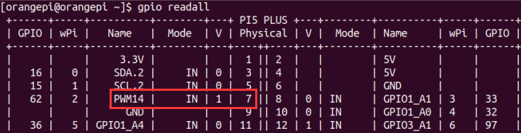
First set the GPIO port as the output mode. The third parameter needs to enter the serial number of the wpi corresponding to the pins
[orangepi@orangepi ~]$ gpio mode 2 out
Then set the GPIO port output low level. After setting, you can use the value of the voltage of the pins with a multimeter. If it is 0V, it means that the low -power flat is set
[orangepi@orangepi ~]$ gpio write 2 0
Then set the GPIO port output high level. After setting, you can use the value of the voltage of the pins with a multimeter. If it is 3.3V, it means that the high -power flat is set to be successful
[orangepi@orangepi ~]$ gpio write 2 1
The setting method of other pins is similar. Just modify the serial number of the wpi serial number as the corresponding serial number.

40 PIN GPIO Port -to -Plattering resistance setting method
Below the No. 7 pin — corresponding to GPIO1_D6 -corresponding WPI serial number 2 -to demonstrate how to set up and down pull -down resistance of the GPIO port
First of all, you need to set the GPIO port as the input mode. The third parameter needs to enter the serial number of the wpi corresponding to the pins
[orangepi@orangepi ~]$ gpio mode 2 in
After the setting is set to input mode, execute the following command to set the GPIO port as the pull -down mode
[orangepi@orangepi ~]$ gpio mode 2 up
Then enter the following command to read the level of the GPIO port. If the level is 1, it means that the drawing mode is successful
[orangepi@orangepi ~]$ gpio read 2
1
Then execute the following command to set the GPIO port as the drop-down mode
[orangepi@orangepi ~]$ gpio mode 2 down
Then enter the command below to read the level of the GPIO port. If the level is 0, it means that the drop -down mode is set successfully
[orangepi@orangepi ~]$ gpio read 2
0
40 PIN SPI test
As can be seen from the figure below, the SPI available for Orange Pi 5 Plus is SPI0 and SPI4
The corresponding pins corresponding to SPI0 and SPI4 are shown in the table below. SPI4_M1 and SPI4_M2 can only be used at the same time, and they cannot be used at the same time. They are the same SPI4, but they are just getting different pins. Please don't think that they are two different SPI bus.
| SPI0_M2 to 40pin | SPI4_M1 to 40pin | SPI4_M2 to 40pin | |
| MOSI | No. 19 pins | No. 12 pins | No. 8 pins |
| MISO | No. 21 pins | No. 31 pins | No. 10 pins |
| CLK | No. 23 pins | No. 35 pins | No. 22 pins |
| CS0 | No. 24 pins | No. 40 pins | No. 31 pins |
| CS1 | No. 26 pins | No. 38 pins | None |
In the Linux system, the SPI in 40 PIN is closed by default, and it needs to be opened manually to use. The detailed steps are shown below:
First add the following configuration to the /boot/extlinux/extlinux.conf
[orangepi@orangepi ~]$ sudo vim /boot/extlinux/extlinux.conf
LABEL Orange Pi
LINUX /Image
FDT /dtbs/rockchip/rk3588-orangepi-5-plus.dtb
FDTOVERLAYS /dtbs/rockchip/overlay/rk3588-spi0-m2-cs0-cs1-spidev.dtbo
The red font demonstrated the configuration of opening the SPI0-M2 and using the CS0 and CS1 pin. The other configurations are shown in the table below, and the corresponding dtbo configuration can be added to FDTOVERLAYS
SPI bus dtbo configuration SPI0_M2-cs0 /dtbs/rockchip/overlay/rk3588-spi0-m2-cs0-spidev.dtbo SPI0_M2-cs1 /dtbs/rockchip/overlay/rk3588-spi0-m2-cs1-spidev.dtbo SPI0_M2-cs0-cs1 /dtbs/rockchip/overlay/rk3588-spi0-m2-cs0-cs1-spidev.dtbo SPI4_M1-cs0 /dtbs/rockchip/overlay/rk3588-spi4-m1-cs0-spidev.dtbo SPI4_M1-cs1 /dtbs/rockchip/overlay/rk3588-spi4-m1-cs1-spidev.dtbo SPI4_M1-cs0-cs1 /dtbs/rockchip/overlay/rk3588-spi4-m1-cs0-cs1-spidev.dtbo SPI4_M2-cs0 /dtbs/rockchip/overlay/rk3588-spi4-m2-cs0-spidev.dtbo - Then restart the OPi OS Arch system
After the restart, enter the system first to check whether there is a spidevx.x device node in the Linux system. If it exists, it means that the SPI has been set and can be used directly
[orangepi@orangepi ~]$ ls /dev/spidev*
/dev/spidev0.0 /dev/spidev0.1 /dev/spidev4.0 /dev/spidev4.1
The above is the result displayed after opening the spi0-m2-cs0-cs1-spidev and spi4-m1-cs0-cs1-spidev
Then do not connect the SPI0 or SPI4 MOSI and MISO pins, and run the output result of the spidev_teest as shown below. You can see that the data of TX and RX are inconsistent
[orangepi@orangepi ~]$ sudo spidev_test -v -D /dev/spidev4.0
Or
[orangepi@orangepi ~]$ sudo spidev_test -v -D /dev/spidev0.0
spi mode: 0x0
bits per word: 8
max speed: 500000 Hz (500 KHz)
TX | FF FF FF FF FF FF 40 00 00 00 00 95 FF FF FF FF FF FF FF FF FF FF FF FF FF FF FF FF FF FF F0 0D | ......@.…▒..................▒.
RX | FF FF FF FF FF FF FF FF FF FF FF FF FF FF FF FF FF FF FF FF FF FF FF FF FF FF FF FF FF FF FF FF | ............................….
Then the output of spidev_test, which is then connected to SPI0 or SPI4 MOSI and MISO, is as follows. You can see that the sending and receiving data can be seen, indicating that the SPI loop test is normal
[orangepi@orangepi ~]$ sudo spidev_test -v -D /dev/spidev4.0
Or
[orangepi@orangepi ~]$ sudo spidev_test -v -D /dev/spidev0.0
spi mode: 0x0
bits per word: 8
max speed: 500000 Hz (500 KHz)
TX | FF FF FF FF FF FF 40 00 00 00 00 95 FF FF FF FF FF FF FF FF FF FF FF FF FF FF FF FF FF FF F0 0D | ......@.…▒..................▒.
RX | FF FF FF FF FF FF 40 00 00 00 00 95 FF FF FF FF FF FF FF FF FF FF FF FF FF FF FF FF FF FF F0 0D | ......@.…▒..................▒.
40 pin I2C test
From the table below, the I2C available for Orange Pi 5 Plus is I2C2, I2C4, I2C5, and I2C8. There are four groups of I2C bus
The corresponding pins corresponding to the 4 group I2C bus are shown below. I2C2_M0 and I2C2_M4 can only be used at the same time, and they cannot be used at the same time. They are the same I2C2, but they only receive different pins. Please don't think that they are two different I2C2 bus
| I2C bus | SDA to 40pin | SCL to 40pin |
| I2C2_M0 | No. 3 pin | No. 5 pin |
| I2C2_M4 | No. 10 pin | No. 8 pin |
| I2C4_M3 | No. 22 pin | No. 32 pin |
| I2C5_M3 | No. 27 pin | No. 28 pin |
| I2C8_M2 | No. 29 pin | No. 7 pin |
In the Linux system, the I2C bus in 40 PIN is closed by default, and it needs to be opened manually to use. The detailed steps are shown below:
First add the following configuration in /boot/extlinux/extlinux.conf.
[orangepi@orangepi ~]$ sudo vim /boot/extlinux/extlinux.conf
LABEL Orange Pi
LINUX /Image
FDT /dtbs/rockchip/rk3588-orangepi-5-plus.dtb
FDTOVERLAYS /dtbs/rockchip/overlay/rk3588-i2c2-m0.dtbo
The red font on the above demonstrates the configuration of the i2c2-m0. The other configurations are shown in the table below, and the corresponding dtbo configuration can be added behind FDTOVERLAYS
I2C bus dtbo configuration I2C2_M0 /dtbs/rockchip/overlay/rk3588-i2c2-m0.dtbo I2C2_M4 /dtbs/rockchip/overlay/rk3588-i2c2-m4.dtbo I2C4_M3 /dtbs/rockchip/overlay/rk3588-i2c4-m3.dtbo I2C5_M3 /dtbs/rockchip/overlay/rk3588-i2c5-m3.dtbo I2C8_M2 /dtbs/rockchip/overlay/rk3588-i2c8-m2.dtbo - Then restart the OPi OS Arch system
After starting the linux system, first confirm that there is a device node that needs to be used under the /dev
orangepi@orangepi:~$ ls /dev/i2c-*
Then connect a I2C device on the I2C pin corresponding to the 40 PIN interface
Then use the i2cdetect -y command to detect the address of the connected i2c device, which means that the i2c can be used normally
[orangepi@orangepi ~]$ sudo pacman -S i2c-tools #First of all, I2C tools
[orangepi@orangepi ~]$ sudo i2cdetect -y 2 #i2c2 test command
[orangepi@orangepi ~]$ sudo i2cdetect -y 4 #i2c4 test command
[orangepi@orangepi ~]$ sudo i2cdetect -y 5 #i2c5 test command
[orangepi@orangepi ~]$ sudo i2cdetect -y 8 #i2c8 test command
40 Pin's UART test
As can be seen from the table below, the UART available for Orange Pi 5 Plus is UART1, UART3, UART4, UART6, UART7, and UART8. There are 6 sets of UART bus
In the Linux system, the UART in 40 pin is closed by default, and it needs to be opened manually to use. The detailed steps are shown below:
First add the following configuration to the /boot/extlinux/extlinux.conf
[orangepi@orangepi ~]$ sudo vim /boot/extlinux/extlinux.conf
LABEL Orange Pi
LINUX /Image
FDT /dtbs/rockchip/rk3588-orangepi-5-plus.dtb
FDTOVERLAYS /dtbs/rockchip/overlay/rk3588-uart1-m1.dtbo
The red font demonstrates the configuration of the uart1-m1. The other configurations are shown in the table below, and the corresponding dtbo configuration can be added behind FDTOVERLAYS
UART bus dtbo configuration UART1_M1 /dtbs/rockchip/overlay/rk3588-uart1-m1.dtbo UART3_M1 /dtbs/rockchip/overlay/rk3588-uart3-m1.dtbo UART4_M2 /dtbs/rockchip/overlay/rk3588-uart4-m2.dtbo UART6_M1 /dtbs/rockchip/overlay/rk3588-uart6-m1.dtbo UART7_M2 /dtbs/rockchip/overlay/rk3588-uart7-m2.dtbo UART8_M1 /dtbs/rockchip/overlay/rk3588-uart8-m1.dtbo - Then restart the OPI OS Arch system
After entering the Linux system, first confirm whether there is a device node corresponding to UART under the /dev
[orangepi@orangepi ~]$ ls /dev/ttyS*
Then start testing the UART interface, and first use the RX and TX pins of the UART interface to be tested by DuPont
| UART bus | RX to 40pin | TX to 40pin |
| UART1_M1 | No. 27 pin | No. 28 pin |
| UART3_M1 | No. 18 pin | No. 16 pin |
| UART4_M2 | No. 19 pin | No. 23 pin |
| UART6_M1 | No. 10 pin | No. 8 pin |
| UART7_M2 | No. 24 pin | No. 26 pin |
| UART8_M1 | No. 40 pin | No. 35 pin |
Use the gpio serial command to test the loop function of the serial port as shown below. If you can see the printed below, it means that the serial port communication is normal (TTYSX needs to be replaced with a node name corresponding to UART, please do not copy it)
[orangepi@orangepi ~]$ sudo gpio serial /dev/ttySX
[sudo] password for orangepi: #Enter the password here
Out: 0: -> 0
Out: 1: -> 1
Out: 2: -> 2
Out: 3: -> 3
Out: 4: -> 4
Out: 5: -> 5^C
PWM test method
From the table below, the PWMs available for Orange Pi 5 Plus include PWM0, PWM1, PWM11, PWM12, PWM13, and PWM14 a total of six PWM
The corresponding pins of PWM in 40pin are shown below. PWM0_M0 and PWM0_M2, PWM1_M0 and PWM1_M2, PWM14_M0 and PWM14_M2 can only be used at the same time. They cannot be used at the same time. They are the same PWM, but they only get different pins. Please think that they are two different PWM bus
| PWM bus | Corresponding 40pin |
| PWM0_M0 | No. 5 pin |
| PWM0_M2 | No. 22 pin |
| PWM1_M0 | No. 3 pin |
| PWM1_M2 | No. 32 pin |
| PWM11_M0 | No. 12 pin |
| PWM12_M0 | No. 14 pin |
| PWM13_M0 | No. 16 pin |
| PWM14_M0 | No. 33 pin |
| PWM14_M2 | No. 7 pin |
In the Linux system, the PWM in 40 PIN is closed by default, and it needs to be opened manually to use. The detailed steps are shown below:
First add the following configuration to the /boot/extlinux/extlinux.conf
[orangepi@orangepi ~]$ sudo vim /boot/extlinux/extlinux.conf
LABEL Orange Pi
LINUX /Image
FDT /dtbs/rockchip/rk3588-orangepi-5-plus.dtb
FDTOVERLAYS /dtbs/rockchip/overlay/rk3588-pwm0-m0.dtbo
The red font demonstrates the configuration of the pwm0-m0. The other configurations are shown in the table below, and the corresponding dtbo configuration can be added behind FDTOVERLAYS
PWM bus Dtbo configuration PWM0_M0 /dtbs/rockchip/overlay/rk3588-pwm0-m0.dtbo PWM0_M2 /dtbs/rockchip/overlay/rk3588-pwm0-m2.dtbo PWM1_M0 /dtbs/rockchip/overlay/rk3588-pwm1-m0.dtbo PWM1_M2 /dtbs/rockchip/overlay/rk3588-pwm1-m2.dtbo PWM11_M0 /dtbs/rockchip/overlay/rk3588-pwm11-m0.dtbo PWM12_M0 /dtbs/rockchip/overlay/rk3588-pwm12-m0.dtbo PWM13_M0 /dtbs/rockchip/overlay/rk3588-pwm13-m0.dtbo PWM14_M0 /dtbs/rockchip/overlay/rk3588-pwm14-m0.dtbo PWM14_M2 /dtbs/rockchip/overlay/rk3588-pwm14-m2.dtbo - Then restart the OPi OS Arch system
After opening a pwm,In the /sys/class/pwm/, there will be an additional pwmchipX (x is a specific number). For example, after opening PWM14,viewing /sys/class/pwm/ down Pwmchipx will change from two to three.
[orangepi@orangepi ~]$ ls /sys/class/pwm/
pwmchip0 pwmchip1 pwmchip2
Which pwmchip corresponds to pwm14 above? Let's first check out the output of ls /sys/class/pwm/ -l command, as shown below:
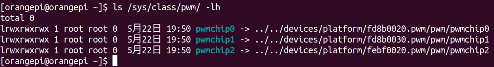
Then from the table below, the base address of the PWM14 register is FEBF0020, and then look at the output of the ls /sys/class/pwm/ -l command. You can see that the link in PWMCHIP2 is connected to Febf0020.PWM, so the PWM14 corresponds to PWMCHIP2
Then use the following command to allow the PWM14 to output a 50Hz square wave (please switch to the root user first, and then execute the following command)

|
[root@orangepi ~]# echo 0 > /sys/class/pwm/pwmchip2/export [root@orangepi ~]# echo 20000000 > /sys/class/pwm/pwmchip2/pwm0/period [root@orangepi ~]# echo 1000000 > /sys/class/pwm/pwmchip2/pwm0/duty_cycle [root@orangepi ~]# echo 1 > /sys/class/pwm/pwmchip2/pwm0/enable |

- The other pwm testing methods in the pwm14 demonstration above are similar.
CAN's test method
How to open a can
As can be seen from the table below, the Canal bus available for Orange Pi 5 Plus is CAN0 and CAN1
In the Linux system, the Can in 40 PIN is closed by default and needs to be opened manually to use. The detailed steps are shown below:
First add the following configuration to the /boot/extlinux/extlinux.conf
[orangepi@orangepi ~]$ sudo vim /boot/extlinux/extlinux.conf
LABEL Orange Pi
LINUX /Image
FDT /dtbs/rockchip/rk3588-orangepi-5-plus.dtb
FDTOVERLAYS /dtbs/rockchip/overlay/rk3588-can0-m0.dtbo
The red font demonstrates the configuration of the can0-m0. The other configurations are shown in the table below, and the corresponding dtbo configuration can be added to FDTOVERLAYS
CAN bus Dtbo configuration can0-m0 /dtbs/rockchip/overlay/rk3588-can0-m0.dtbo can1-m0 /dtbs/rockchip/overlay/rk3588-can1-m0.dtbo - Then restart the OPI OS Arch system
After entering the Linux system, using the sudo ifconfig -a command If you can see the CAN device node, it means that the CAN has been opened correctly
[orangepi@orangepi ~]$ sudo pacman -Syy net-tools
[orangepi@orangepi ~]$ sudo ifconfig -a
can0: flags=128<NOARP> mtu 16
unspec 00-00-00-00-00-00-00-00-00-00-00-00-00-00-00-00 txqueuelen 10 (UNSPEC)
RX packets 0 bytes 0 (0.0 B)
RX errors 0 dropped 0 overruns 0 frame 0
TX packets 0 bytes 0 (0.0 B)
TX errors 0 dropped 0 overruns 0 carrier 0 collisions 0
device interrupt 94
can1: flags=128<NOARP> mtu 16
unspec 00-00-00-00-00-00-00-00-00-00-00-00-00-00-00-00 txqueuelen 10 (UNSPEC)
RX packets 0 bytes 0 (0.0 B)
RX errors 0 dropped 0 overruns 0 frame 0
TX packets 0 bytes 0 (0.0 B)
TX errors 0 dropped 0 overruns 0 carrier 0 collisions 0
device interrupt 95
The pins corresponding to the Can0 and Can1 are
| CAN0 | CAN1 | |
| TX Pin | Corresponding to No. 5 pin in 40pin | Corresponding to No. 18 pin in 40pin |
| RX Pin | Corresponding to No. 3 pin in 40pin | Corresponding to No. 16 pin in 40pin |
- Use Canalyst-II analyzer to test CAN receiving messages, please refer to the content of the one-section of the Canalyst-II analyzer to test receive and send message
Linux SDK——orangepi-build instructions
Compilation system requirements
|
We can cross-compile the Linux image of the development board on the x64 computer, or compile the Linux image of the development board on the Ubuntu22.04 system of the development board, please choose one according to your preference. If you use orangepi-build to compile the Linux image in the Ubuntu22.04 system of the development board, please do a good job of cooling (especially when the SSD starts). If the heat dissipation is not done well, it is prone to the error of file system runaway. |
Compile with the Ubuntu22.04 system of the development board
The Linux SDK, namely orangepi-build, supports running on the Ubuntu 22.04 of the development board (other systems have not been tested), so before downloading orangepi-build, please first ensure that the Ubuntu version installed on the development board is Ubuntu 22.04. The command to check the Ubuntu version installed on the development board is as follows. If the Release field does not display 22.04, it means that the current Ubuntu version does not meet the requirements. Please replace the system before performing the following operations.
orangepi@orangepi:~$ lsb_release -a
No LSB modules are available.
Distributor ID: Ubuntu
Description: Ubuntu 22.04.1 LTS
Release: 22.04
Codename: jammy
Since the source codes such as the kernel and U-boot are stored on GitHub, it is very important to ensure that the development board can download codes from GitHub normally when compiling the image.
Compile with x64 Ubuntu22.04 computer
The Linux SDK, orangepi-build, supports running on computers with Ubuntu 22.04 installed, so before downloading orangepi-build, please make sure that the Ubuntu version installed on your computer is Ubuntu 22.04. The command to check the Ubuntu version installed on the computer is as follows. If the Release field does not display 22.04, it means that the current Ubuntu version does not meet the requirements. Please replace the system before performing the following operations.
test@test:~$ lsb_release -a
No LSB modules are available.
Distributor ID: Ubuntu
Description: Ubuntu 22.04 LTS
Release: 22.04
Codename: jammy
If the computer is installed with Windows system and there is no computer with Ubuntu 22.04 installed, you can consider using VirtualBox or VMware to install an Ubuntu 22.04 virtual machine in the Windows system. But please be careful not to compile orangepi-build on the WSL virtual machine, because orangepi-build has not been tested in the WSL virtual machine, so it cannot be guaranteed that orangepi-build can be used normally in WSL.
The download address of the installation image of Ubuntu 22.04 amd64 version is:
https://mirrors.tuna.tsinghua.edu.cn/ubuntu-releases/22.04/ubuntu-22.04-desktop-amd64.iso
or
https://repo.huaweicloud.com/ubuntu-releases/22.04/ubuntu-22.04.1-desktop-amd64.iso
After installing Ubuntu 22.04 on the computer or virtual machine, please set the software source of Ubuntu 22.04 to Tsinghua source, otherwise it is easy to make mistakes due to network reasons when installing the software later
- For the method of replacing Tsinghua source, please refer to the instructions on this web page
Note that the Ubuntu version needs to be switched to 22.04
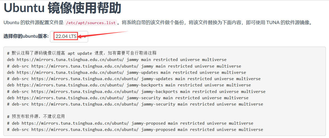
The content of the /etc/apt/sources.list file that needs to be replaced is
test@test:~$ sudo mv /etc/apt/sources.list /etc/apt/sources.list.bak
test@test:~$ sudo vim /etc/apt/sources.list
# By default, the source image is commented to improve the speed of apt update, you can uncomment it yourself if necessary
deb https://mirrors.tuna.tsinghua.edu.cn/ubuntu/ jammy main restricted universe multiverse
# deb-src https://mirrors.tuna.tsinghua.edu.cn/ubuntu/ jammy main restricted universe multiverse
deb https://mirrors.tuna.tsinghua.edu.cn/ubuntu/ jammy-updates main restricted universe multiverse
# deb-src https://mirrors.tuna.tsinghua.edu.cn/ubuntu/ jammy-updates main restricted universe multiverse
deb https://mirrors.tuna.tsinghua.edu.cn/ubuntu/ jammy-backports main restricted universe multiverse
# deb-src https://mirrors.tuna.tsinghua.edu.cn/ubuntu/ jammy-backports main restricted universe multiverse
deb https://mirrors.tuna.tsinghua.edu.cn/ubuntu/ jammy-security main restricted universe multiverse
# deb-src https://mirrors.tuna.tsinghua.edu.cn/ubuntu/ jammy-security main restricted universe multiverse
# Pre-release software source, not recommended to enable
# deb https://mirrors.tuna.tsinghua.edu.cn/ubuntu/ jammy-proposed main restricted universe multiverse
# deb-src https://mirrors.tuna.tsinghua.edu.cn/ubuntu/ jammy-proposed main restricted universe multiverse
After the replacement, you need to update the package information and make sure there is no error
test@test:~$ sudo apt update
In addition, since the source codes such as the kernel and U-boot are stored on GitHub, it is very important to ensure that the computer can download codes from GitHub normally when compiling the image.

Get the source code of linux sdk
Download orangepi-build from github
- The linux sdk actually refers to the code of orangepi-build. orangepi-build is modified based on the armbian build system. Using orangepi-build, multiple versions of linux images can be compiled. First download the code of orangepi-build, the command is as follows:
test@test:~$ sudo apt-get update
test@test:~$ sudo apt-get install -y git
test@test:~$ git clone https://github.com/orangepi-xunlong/orangepi-build.git -b next
Note that the Orange Pi 5 Plus development board needs to download the source code of the next branch of orangepi-build. The above git clone command needs to specify the branch of the orangepi-build source code as next.
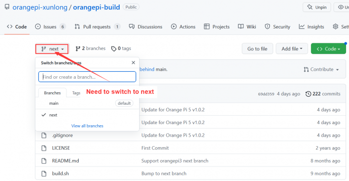

Downloading the orangepi-build code through the git clone command does not require entering the user name and password of the github account (the same is true for downloading other codes in this manual), if the Ubuntu PC prompts the user to enter the github account after entering the git clone command The name and password are usually entered incorrectly in the address of the orangepi-build warehouse behind the git clone. Please check the spelling of the command carefully, instead of thinking that we forgot to provide the username and password of the github account.
- The u-boot and linux kernel versions currently used by the development board are as follows
| branch | u-boot version | linux kernel version |
| legacy | u-boot 2017.09 | linux5.10 |
|
The branch mentioned here is not the same thing as the branch of the orangepi-build source code, please do not confuse it. This branch is mainly used to distinguish different kernel source code versions. Currently, the linux5.10 bsp kernel provided by RK is defined as the legacy branch. If the mainline kernel is supported in the future, a current branch will be added. |
orangepi-build will contain the following files and folders after downloading
build.sh: Compile the startup script
external: Contains the configuration files needed to compile the image, specific scripts, and the source code of some programs, etc.
LICENSE: GPL 2 license file
README.md: orangepi-build documentation
scripts: General script for compiling linux images
test@test:~/orangepi-build$ ls
build.sh external LICENSE README.md scripts
If you downloaded the code of orangepi-build from github, after downloading, you may find that orangepi-build does not contain the source code of u-boot and linux kernel, nor does u-boot and linux kernel need to use cross-compilation tools Chain, this is normal, because these things are stored in other separate github warehouses or some servers (the addresses will be detailed below). orangepi-build will specify the address of u-boot, linux kernel and cross-compilation toolchain in the script and configuration file. When running orangepi-build, when it finds that there are no such things locally, it will automatically go to the corresponding place to download them.
Download the cross-compilation toolchain
|
The cross-compilation toolchain will only be downloaded when the orangepi-build compilation image is used on an x64 computer. Compiling the linux image of the development board in the Ubuntu22.04 of the development board will not download the cross-compilation toolchain. At this time, orangepi-build/toolchains will be an empty folder. |
When orangepi-build runs for the first time, it will automatically download the cross-compilation toolchain and put it in the toolchains folder. Every time after running the build.sh script of orangepi-build, it will check whether the cross-compilation toolchain in toolchains exists , if it does not exist, the download will be restarted, if it exists, it will be used directly, and the download will not be repeated.
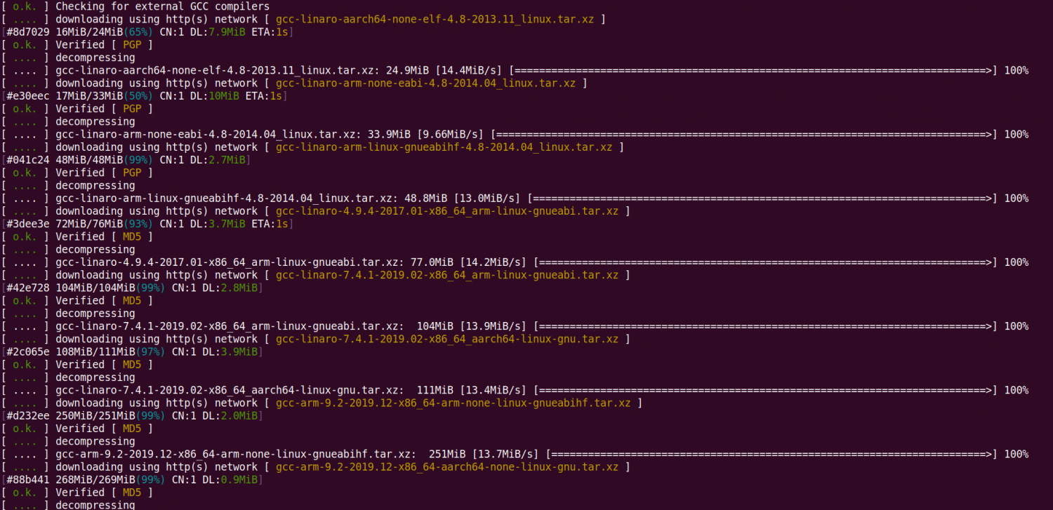
The image URL of the cross-compilation toolchain in China is the open source software image site of Tsinghua University
https://mirrors.tuna.tsinghua.edu.cn/armbian-releases/_toolchain/
After toolchains is downloaded, it will contain multiple versions of cross-compilation toolchains, and the development board will only use two of them
test@test:~/orangepi-build$ ls toolchains/
gcc-arm-11.2-2022.02-x86_64-aarch64-none-linux-gnu
gcc-arm-11.2-2022.02-x86_64-arm-none-linux-gnueabihf
gcc-arm-9.2-2019.12-x86_64-aarch64-none-linux-gnu
gcc-arm-9.2-2019.12-x86_64-arm-none-linux-gnueabihf
gcc-linaro-4.9.4-2017.01-x86_64_arm-linux-gnueabi
gcc-linaro-5.5.0-2017.10-x86_64_arm-linux-gnueabihf
gcc-linaro-7.4.1-2019.02-x86_64_aarch64-linux-gnu
gcc-linaro-7.4.1-2019.02-x86_64_arm-linux-gnueabi
gcc-linaro-aarch64-none-elf-4.8-2013.11_linux
gcc-linaro-arm-linux-gnueabihf-4.8-2014.04_linux
gcc-linaro-arm-none-eabi-4.8-2014.04_linux
The cross-compilation toolchain used to compile the linux kernel source code is
linux5.10
gcc-arm-11.2-2022.02-x86_64-aarch64-none-linux-gnu
The cross-compilation tool chain used to compile the u-boot source code is
v2017.09
gcc-linaro-7.4.1-2019.02-x86_64_aarch64-linux-gnu

orangepi-build complete directory structure description
The orangepi-build repository does not contain the source code of the linux kernel, u-boot, and cross-compilation toolchain after downloading. The source code of the linux kernel and u-boot is stored in an independent git repository
The git warehouse where the linux kernel source code is stored is as follows:
https://github.com/orangepi-xunlong/linux-orangepi/tree/orange-pi-5.10-rk3588
The git warehouse where the u-boot source code is stored is as follows:
https://github.com/orangepi-xunlong/u-boot-orangepi/tree/v2017.09-rk3588
When orangepi-build runs for the first time, it will download the cross-compilation toolchain, u-boot and linux kernel source code. After successfully compiling a linux image, the files and folders that can be seen in orangepi-build are:
a. build.sh: compile startup script
b. external: Contains the configuration files needed to compile the image, scripts with specific functions, and the source code of some programs. The rootfs compressed package cached during the image compilation process is also stored in external
c. kernel: stores the source code of the linux kernel. The folder named orange-pi-5.10-rk3588 stores the kernel source code of the legacy branch of the RK3588/RK3588S series development boards. Please do not manually modify the name of the folder of the kernel source code. If it is modified, the kernel source code will be re-downloaded when the compilation system is running
d. LICENSE: GPL 2 license file
e. README.md: orangepi-build documentation
f. output: Store compiled deb packages such as u-boot and linux, compilation logs, and compiled images and other files
g. scripts: general scripts for compiling linux images
h. toolchains: store cross-compilation toolchain
i. u-boot: Store the source code of u-boot. The folder named v2017.09-rk3588 stores the u-boot source code of the legacy branch of the RK3588/RK3588S series development boards. Please do not name the folder name of the u-boot source code Manual modification, if modified, the u-boot source code will be re-downloaded when the compilation system is running
j. userpatches: Store configuration files needed to compile scripts
test@test:~/orangepi-build$ ls
build.sh external kernel LICENSE output README.md scripts toolchains u-boot userpatches
Compile u-boot
Run the build.sh script, remember to add sudo permission
test@test:~/orangepi-build$ sudo ./build.sh
Select U-boot package, then press Enter
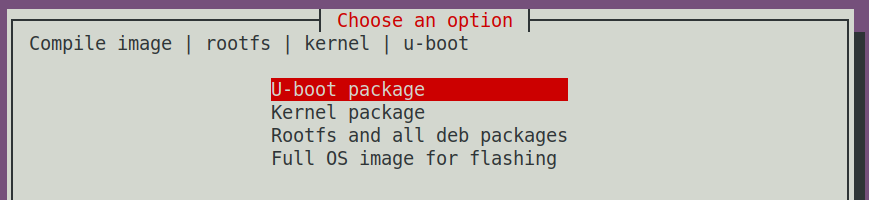
Then select the model of the development board
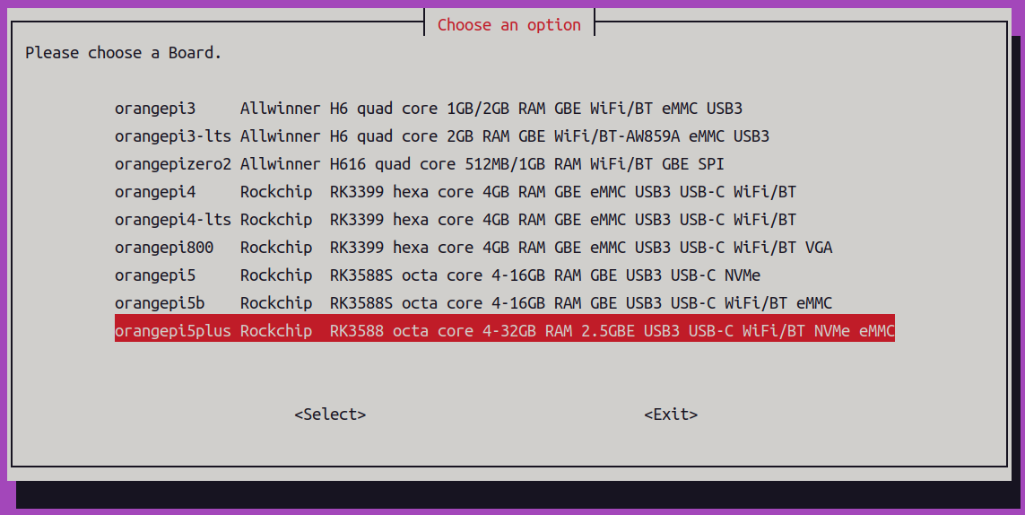
Then it will start to compile u-boot, and some information prompted during compilation is explained as follows
u-boot source code version
[ o.k. ] Compiling u-boot [ v2017.09 ]
The version of the cross-compilation toolchain
[ o.k. ] Compiler version [ aarch64-linux-gnu-gcc 7.4.1 ]
Path to the generated u-boot deb package
[ o.k. ] Target directory [ orangepi-build/output/debs/u-boot ]
The package name of the generated u-boot deb package
[ o.k. ] File name [ linux-u-boot-legacy-orangepi5plus_1.0.0_arm64.deb ]
Compilation time
[ o.k. ] Runtime [ 1 min ]
Repeat the command to compile u-boot, use the following command to start compiling u-boot directly without selecting through the graphical interface
[ o.k. ] Repeat Build Options [ sudo ./build.sh BOARD=orangepi5plus BRANCH=legacy BUILD_OPT=u-boot KERNEL_CONFIGURE=no ]
View the u-boot deb package generated by compilation
test@test:~/orangepi-build$ ls output/debs/u-boot/
linux-u-boot-legacy-orangepi5plus_1.0.0_arm64.deb
The files contained in the generated u-boot deb package are as follows
Use the following command to decompress the deb package
test@test:~/orangepi-build$ cd output/debs/u-boot
test@test:~/orangepi_build/output/debs/u-boot$ $ sudo dpkg -x \
linux-u-boot-legacy-orangepi5plus_1.0.0_arm64.deb . (Note that there is a "." at the end of the command)
test@test:~/orangepi_build/output/debs/u-boot$ ls
linux-u-boot-legacy-orangepi5plus_1.0.0_arm64.deb usr
The decompressed file is as follows
test@test:~/orangepi-build/output/debs/u-boot$ tree usr
usr
└── lib
├── linux-u-boot-legacy-orangepi5plus_1.0.0_arm64
│ ├── idbloader.img
│ ├── rkspi_loader.img
│ └── u-boot.itb
└── u-boot
├── LICENSE
├── orangepi_5_plus_defconfig
└── platform_install.sh
3 directories, 6 files
When the orangepi-bulid compilation system compiles the u-boot source code, it will first synchronize the u-boot source code with the u-boot source code of the github server, so if you want to modify the u-boot source code, you first need to turn off the download and update function of the source code (need This function can only be turned off after u-boot has been fully compiled, otherwise it will prompt that the source code of u-boot cannot be found. If the source code compressed package is downloaded from Google Drive, there is no such problem because the source code of u-boot cached), otherwise the changes made will be restored, the method is as follows:
Set the IGNORE_UPDATES variable in userpatches/config-default.conf to "yes"
test@test:~/orangepi-build$ vim userpatches/config-default.conf
IGNORE_UPDATES="yes"
When debugging u-boot code, you can use the following method to update u-boot in the linux image for testing
Upload the compiled u-boot deb package to the linux system of the development board
test@test:~/orangepi-build$ cd output/debs/u-boot
test@test:~/orangepi_build/output/debs/u-boot$ scp \
linux-u-boot-legacy-orangepi5plus_1.0.0_arm64.deb root@192.168.1.xxx:/root
Then log in to the development board and uninstall the deb package of u-boot installed
root@orangepi:~# apt purge -y linux-u-boot-orangepi5plus-legacy
Install the new u-boot deb package just uploaded
root@orangepi:~# dpkg -i linux-u-boot-legacy-orangepi5plus_1.0.0_arm64.deb
Then run the nand-sata-install script
root@orangepi:~# nand-sata-install
Then select 5 Install/Update the bootloader on SD/eMM to update the u-boot in the TF card or 7 Install/Update the bootloader on SPI Flash to update the u-boot in the SPI Flash
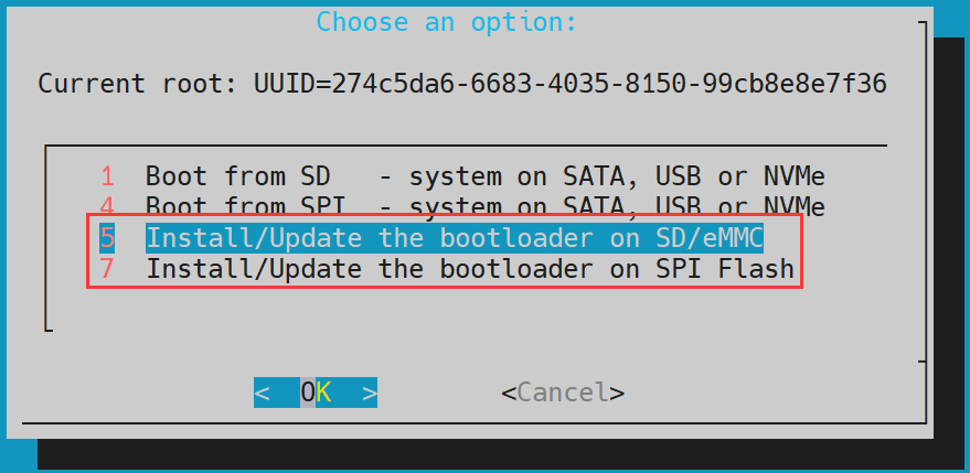
After pressing the Enter key, a Warning will pop up first
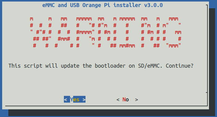
Press the Enter key again to start updating u-boot, and the following information will be displayed after the update is completed
Then you can restart the development board to test whether the modification of u-boot takes effect
Other useful information
u-boot 2017.09 source code, the defconfig configuration file used by the development board is
u-boot 2017.09 source code, the dts file used by the development board is
orangepi-build/u-boot/v2017.09-rk3588/configs/orangepi_5_plus_defconfig
orangepi-build/u-boot/v2017.09-rk3588/arch/arm/dts/rk3588-orangepi-5-plus.dts


Compile the linux kernel
Run the build.sh script, remember to add sudo permission
test@test:~/orangepi-build$ sudo ./build.sh
Select Kernel package, then press Enter
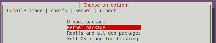
Then select the model of the development board
Then it will prompt whether to display the kernel configuration interface. If you do not need to modify the kernel configuration, select the first one. If you need to modify the kernel configuration, select the second one.

If you choose to display the kernel configuration menu (the second option) in step 4), the kernel configuration interface opened by make menuconfig will pop up. At this time, you can directly modify the kernel configuration, save and exit after modification. Yes, after exiting, the kernel source code will be compiled
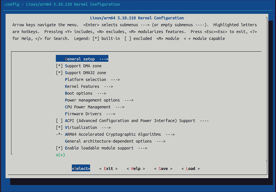


If you do not need to modify the configuration options of the kernel, when running the build.sh script, pass in KERNEL_CONFIGURE=no to temporarily block the pop-up kernel configuration interface
test@test:~/orangepi-build$ sudo ./build.sh KERNEL_CONFIGURE=no
You can also set KERNEL_CONFIGURE=no in the orangepi-build/userpatches/config-default.conf configuration file, which can permanently disable this function
If the following error is displayed when compiling the kernel, it is because the terminal interface of the Ubuntu PC is too small to display the make menuconfig interface. Please maximize the terminal of the Ubuntu PC and run the build.sh script again
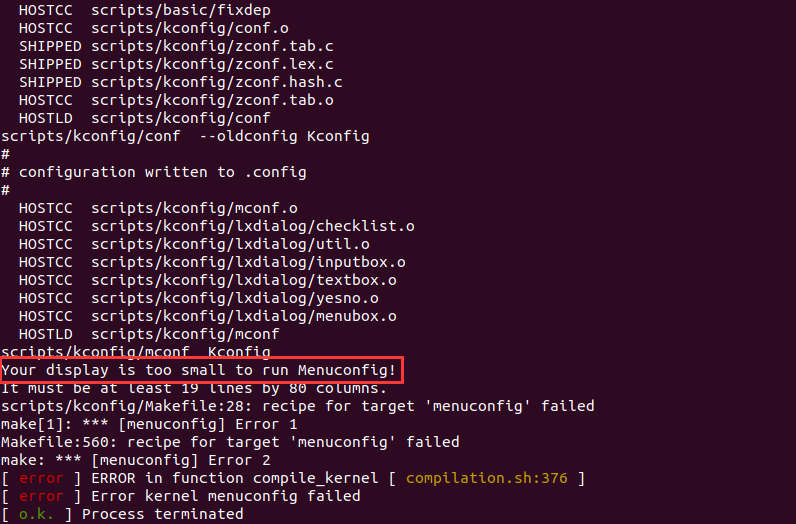

Part of the information prompted when compiling the kernel source code is as follows
The version of the linux kernel source code
[ o.k. ] Compiling current kernel [ 5.10.110 ]
The version of the cross-compilation toolchain used
[ o.k. ] Compiler version [ aarch64-none-linux-gnu-gcc 11.2.1 ]
The configuration file used by the kernel by default and the path where it is stored
[ o.k. ] Using kernel config file [ config/kernel/linux-rockchip-rk3588-legacy.config ]
The path of the deb package related to the kernel generated by compiling
[ o.k. ] Target directory [ orangepi-build/output/debs/ ]
The package name of the compiled kernel image deb package
[ o.k. ] File name [ linux-image-legacy-rockchip-rk3588_1.0.0_arm64.deb ]
The time used for compilation
[ o.k. ] Runtime [ 5 min ]
Finally, the compilation command to repeatedly compile the kernel selected last time will be displayed. Use the following command to start compiling the kernel source code directly without selecting through the graphical interface
[ o.k. ] Repeat Build Options [ sudo ./build.sh BOARD=orangepi5plus BRANCH=legacy BUILD_OPT=kernel KERNEL_CONFIGURE=no ]
View the deb package related to the kernel generated by compilation
linux-dtb-legacy-rockchip-rk3588_1.0.0_arm64.deb Contains dtb files used by the kernel
linux-headers-legacy-rockchip-rk3588_1.0.0_arm64.deb Include kernel headers
linux-image-legacy-rockchip-rk3588_1.0.0_arm64.deb Contains kernel images and kernel modules
test@test:~/orangepi-build$ ls output/debs/linux-*
output/debs/linux-dtb-legacy-rockchip-rk3588_1.0.0_arm64.deb
output/debs/linux-image-legacy-rockchip-rk3588_1.0.0_arm64.deb
output/debs/linux-headers-legacy-rockchip-rk3588_1.0.0_arm64.deb
The files contained in the generated linux-image deb package are as follows
Use the following command to decompress the deb package
test@test:~/orangepi-build$ cd output/debs
test@test:~/orangepi_build/output/debs$ mkdir test
test@test:~/orangepi_build/output/debs$ cp \
linux-image-legacy-rockchip-rk3588_1.0.0_arm64.deb test/
test@test:~/orangepi_build/output/debs$ cd test
test@test:~/orangepi_build/output/debs/test$ dpkg -x \
linux-image-legacy-rockchip-rk3588_1.0.0_arm64.deb .
test@test:~/orangepi_build/output/debs/test$ ls
boot etc lib linux-image-legacy-rockchip-rk3588_1.0.0_arm64.deb usr
The decompressed file is as follows
test@test:~/orangepi-build/output/debs/test$ tree -L 2
.
├── boot
│ ├── config-5.10.110-rockchip-rk3588
│ ├── System.map-5.10.110-rockchip-rk3588
│ └── vmlinuz-5.10.110-rockchip-rk3588
├── etc
│ └── kernel
├── lib
│ └── modules
├── linux-image-legacy-rockchip-rk3588_1.0.0_arm64.deb
└── usr
├── lib
└── share
The orangepi-bulid compilation system will first synchronize the linux kernel source code with the linux kernel source code of the github server when compiling the linux kernel source code, so if you want to modify the linux kernel source code, you first need to turn off the update function of the source code (you need to compile it once This function can only be turned off after the linux kernel source code, otherwise it will prompt that the source code of the linux kernel cannot be found. If the source code compressed package downloaded from Google Drive, there is no such problem, because the source code of linux has been cached), otherwise the The changes made will be reverted as follows:
Set the IGNORE_UPDATES variable in userpatches/config-default.conf to "yes"
test@test:~/orangepi-build$ vim userpatches/config-default.conf
IGNORE_UPDATES="yes"
If the kernel has been modified, the following method can be used to update the kernel and kernel modules of the development board linux system
Upload the deb package of the compiled linux kernel to the linux system of the development board
test@test:~/orangepi-build$ cd output/debs
test@test:~/orangepi-build/output/debs$ scp \
linux-image-legacy-rockchip-rk3588_1.0.0_arm64.deb root@192.168.1.xxx:/root
Then log in to the development board and uninstall the deb package of the installed linux kernel
root@orangepi:~# apt purge -y linux-image-legacy-rockchip-rk3588
Install the deb package of the new linux kernel just uploaded
root@orangepi:~# dpkg -i linux-image-legacy-rockchip-rk3588_1.0.0_arm64.deb
Then restart the development board, and then check whether the kernel-related modifications have taken effect
root@orangepi:~# reboot
Other useful information
The storage location of the kernel configuration file is as follows, please do not go to the kernel source code to find the kernel configuration file used by the development board
The location of the dts file used by the development board is
orangepi-build/external/config/kernel/linux-rockchip-rk3588-legacy.config
orangepi-build/kernel/orange-pi-5.10-rk3588/arch/arm64/boot/dts/rockchip/rk3588-orangepi-5-plus.dts
Compile rootfs
Run the build.sh script, remember to add sudo permission
test@test:~/orangepi-build$ sudo ./build.sh
Select Rootfs and all deb packages, then press Enter

Then select the model of the development board
Then select the type of rootfs (mainly maintain bullseye/focal/jammy at present)
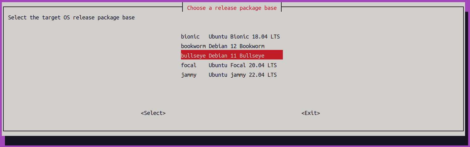
Then select the type of image
Image with console interface (server) Indicates the image of the server version, which is relatively small
Image with desktop environment Indicates a mirror image with a desktop, which is relatively large

If you are compiling the image of the server version, you can also choose to compile the Standard version or the Minimal version. The pre-installed software of the Minimal version will be much less than that of the Standard version (please do not choose the Minimal version if there is no special requirement, because many things are not pre-installed by default. Some functions may not be available)

If you are compiling the image of the desktop version, you need to select the type of desktop environment. Currently, Ubuntu Jammy mainly maintains XFCE and Gnome desktops, Ubuntu Focal only maintains XFCE desktops, and Debian Bullseye mainly maintains XFCE and KDE desktops
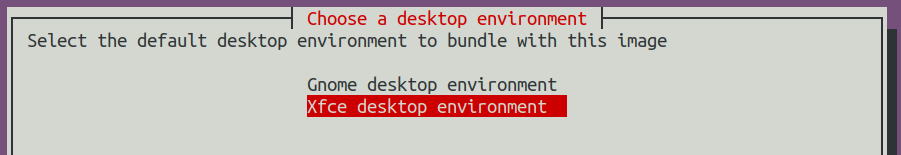

You can then select additional packages that need to be installed. Please press the Enter key to skip directly here.
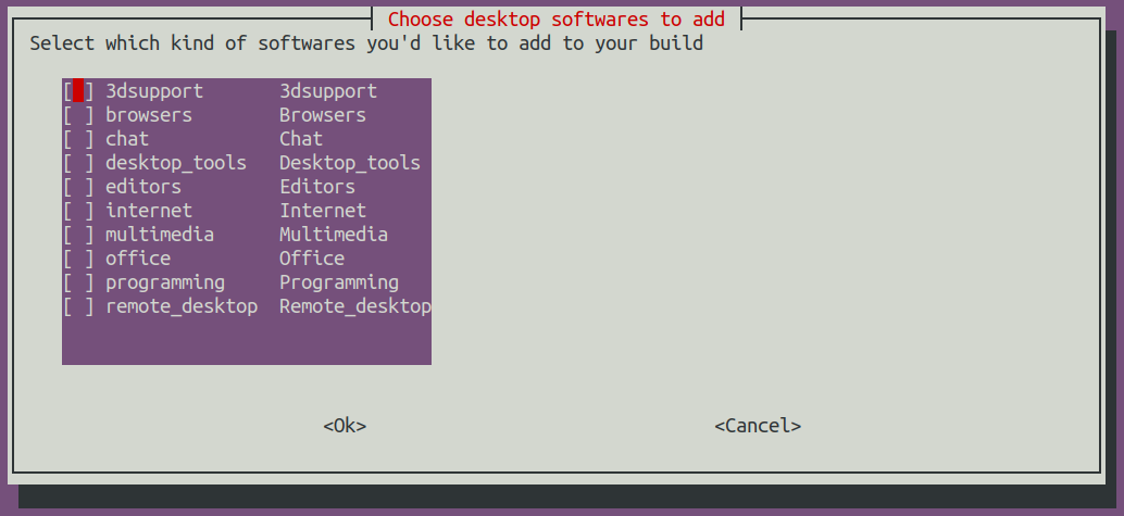
Then it will start to compile rootfs, and some of the information prompted during compilation are as follows
The type of rootfs
[ o.k. ] local not found [ Creating new rootfs cache for jammy]
The storage path of the compiled rootfs compressed package
[ o.k. ] Target directory [ external/cache/rootfs ]
The name of the rootfs compressed package generated by compilation
[ o.k. ] File name [ jammy-xfce-arm64.f930ff6ebbac1a72108a2e100762b18f.tar.lz4 ]
The time used for compilation
[ o.k. ] Runtime [ 13 min ]
View the rootfs compressed package generated by compilation
jammy-xfce-arm64.f930ff6ebbac1a72108a2e100762b18f.tar.lz4 is the rootfs compressed package, the meaning of each field of the name is
a) jammy indicates the type of linux distribution of rootfs
b) xfce means rootfs is the type of desktop version, if it is cli, it means the type of server version
c) arm64 represents the architecture type of rootfs
d) f930ff6ebbac1a72108a2e100762b18f is the MD5 hash value generated by the package names of all software packages installed by rootfs. As long as the list of software packages installed by rootfs is not modified, this value will not change. The compilation script will use this MD5 hash value to generate Determine whether rootfs needs to be recompiled
jammy-xfce-arm64.f930ff6ebbac1a72108a2e100762b18f.tar.lz4.list lists the package names of all packages installed by rootfs
test@test:~/orangepi-build$ ls external/cache/rootfs/
jammy-xfce-arm64.f930ff6ebbac1a72108a2e100762b18f.tar.lz4
jammy-xfce-arm64.f930ff6ebbac1a72108a2e100762b18f.tar.lz4.current
jammy-xfce-arm64.f930ff6ebbac1a72108a2e100762b18f.tar.lz4.list
If the required rootfs already exists under external/cache/rootfs, then compiling rootfs again will directly skip the compilation process and will not restart the compilation. When compiling the image, it will also go to external/cache/rootfs to find out whether it has If there is rootfs available in the cache, use it directly, which can save a lot of download and compilation time.


Compile linux image
Run the build.sh script, remember to add sudo permission
test@test:~/orangepi-build$ sudo ./build.sh
Select Full OS image for flashing, then press Enter

Then select the model of the development board
Then select the type of rootfs (mainly maintain bullseye/focal/jammy at present)
Then select the type of image
Image with console interface (server) Indicates the image of the server version, which is relatively small
Image with desktop environment Indicates a image with a desktop, which is relatively large
If you are compiling the image of the server version, you can also choose to compile the Standard version or the Minimal version. The pre-installed software of the Minimal version will be much less than that of the Standard version (please do not choose the Minimal version if there is no special requirement, because many things are not pre-installed by default. Some functions may not be available)
If you are compiling the image of the desktop version, you need to select the type of desktop environment. Currently, Ubuntu Jammy mainly maintains XFCE and Gnome desktops, Ubuntu Focal only maintains XFCE desktops, and Debian Bullseye mainly maintains XFCE and KDE desktops
You can then select additional packages that need to be installed. Please press the Enter key to skip directly here.
Then it will start to compile the linux image. The general process of compilation is as follows
a. Initialize the compilation environment of Ubuntu PC and install the software packages required for the compilation process
b. Download the source code of u-boot and linux kernel (if cached, only update the code)
c. Compile u-boot source code and generate u-boot deb package
d. Compile the linux source code and generate linux-related deb packages
e. Make the deb package of linux firmware
f. Make the deb package of the orangepi-config tool
g. Create a deb package supported by the board
h. If you are compiling the desktop image, you will also create desktop-related deb packages
i. Check whether the rootfs has been cached, if not, recreate the rootfs, if it has been cached, directly decompress and use
j. Install the previously generated deb package into rootfs
k. Make some specific settings for different development boards and different types of images, such as pre-installing additional software packages, modifying system configuration, etc.
l. Then make an image file and format the partition, the default type is ext4
m. Then copy the configured rootfs to the mirrored partition
n. Then update initramfs
o. Finally, write the bin file of u-boot into the image through the dd command
After compiling the image, the following information will be prompted
The storage path of the compiled image
[ o.k. ] Done building [ output/images/orangepi5plus_1.0.0_debian_bullseye_linux5.10.110_xfce_desktop/orangepi5plus_1.0.0_debian_bullseye_linux5.10.110_xfce_desktop.img ]
Compilation time
[ o.k. ] Runtime [ 19 min ]
Repeat the command to compile the image, and use the following command to start compiling the image directly without selecting through the graphical interface
[ o.k. ] Repeat Build Options [ sudo ./build.sh BOARD=orangepi5plus BRANCH=legacy BUILD_OPT=image RELEASE=bullseye BUILD_MINIMAL=no BUILD_DESKTOP=no KERNEL_CONFIGURE=yes ]
Linux Development Manual
The method of compiling the kernel source code separately in the linux system of the development board
First download the Linux kernel source code of the development board
orangepi@orangepi:~$ git clone --depth=1 -b orange-pi-5.10-rk3588 https://github.com/orangepi-xunlong/linux-orangepi
If you have problems downloading the code from github, you can go to the official tool of the development board to download the compressed kernel source code package, then upload it to the linux system of the development board, and then decompress it.
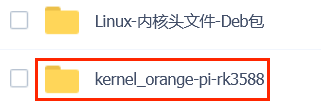
The command to decompress the compressed kernel source code package is:
orangepi@orangepi:~$ tar zxf orange-pi-5.10-rk3588.tar.gz
orangepi@orangepi:~$ mv orange-pi-5.10-rk3588 linux-orangepi
After decompression, please execute the following command to synchronize the source code with github to ensure that the source code is in the latest state:
orangepi@orangepi:~$ cd linux-orangepi
orangepi@orangepi:~/linux-orangepi$ git pull


Then configure the default kernel configuration
orangepi@orangepi:~$ cd linux-orangepi
orangepi@orangepi:~/linux-orangepi$ make rockchip_linux_defconfig
The path of rockchip_linux_defconfig in the kernel source code is arch/arm64/configs/
Then compile the kernel source code
orangepi@orangepi:~/linux-orangepi$ make -j10
Then install the kernel module
orangepi@orangepi:~/linux-orangepi$ sudo make modules_install
The installation path of the kernel module is:/lib/modules
After executing the sudo make modules_install command, you can see that there will be an additional kernel module folder under /lib/modules/:
orangepi@orangepi5plus:~$ ls /lib/modules
5.10.110+ 5.10.110-rockchip-rk3588
Then install the kernel image and uInitrd
orangepi@orangepi:~/linux-orangepi$ sudo make install
The installation path of the kernel image and uInitrd is:/boot/
After executing the sudo make install command, you can see that there will be one more kernel file under /boot/:
orangepi@orangepi5plus:~/orange-pi-5.10-rk3588$ ls /boot/vmlinuz*
/boot/vmlinuz-5.10.110+ /boot/vmlinuz-5.10.110-rockchip-rk3588
The file /boot/Image is actually loaded when the system starts, and Image is a copy of the vmlinuz file
Then install the dtb file into /boot/dtb
orangepi@orangepi:~/linux-orangepi$ sudo make dtbs_install INSTALL_DTBS_PATH=/boot/dtb/
Then restart the Linux system and the newly compiled kernel will be loaded
orangepi@orangepi:~$ uname -r
5.10.110+
OpenWRT system instructions
OpenWRT version
| OpenWRT version | kernel version |
| v22.03.4 | Linux5.10.110 |
OpenWRT Adaptation
| Function | OpenWRT |
| USB2.0x2 | OK |
| USB3.0x2 | OK |
| USB Type-C 3.0 | OK |
| 3pin debugging serial port | OK |
| TF card start | OK |
| SPIFlash+NVMe SSD Boot | OK |
| SPIFlash boots the complete system | OK |
| 2.5G PCIe network port X2 | OK |
| Network port status light | OK |
| led light | OK |
| FAN fan interface | OK |
| AX200-WIFI | OK |
| AX200-WIFI | OK |
| eMMC extension interface | OK |
The first start to expand rootfs
When the OpenWRT system is started for the first time, the resize-rootfs.sh script will be executed to expand the rootfs, and it will automatically restart after the expansion is completed
After logging in to the system, you can use the df -h command to view the size of rootfs. If it is consistent with the actual capacity of the storage device (TF card, eMMC or NVME SSD), it means that the automatic expansion is running correctly
root@OpenWrt:~# df -h
Filesystem Size Used Available Use% Mounted on
/dev/root14.8G14.7G91.6M99% /
tmpfs 495.5M6.1M489.4M1% /tmp
tmpfs 512.0K0512.0K0% /dev
/dev/root14.8G14.7G 91.6M99% /opt/docker
How to log in to the system
Login via serial port
First, to use the debugging serial port, please refer to the chapter on how to use the debugging serial port
The OpenWrt system will automatically log in as the root user by default, and the display interface is as follows
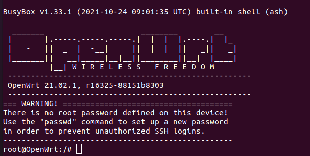

Log in to the system via SSH
|
Please note that in the OpenWrt system of Orange Pi 5 Plus, the network port near the typeC power interface is configured as a WAN port by default, and the network port near the HDMI port is configured as a LAN port by default. |
First connect the LAN port of the board to the network port of the computer with a network cable, so that the network port of the computer can obtain an IP address through DHCP
The LAN port IP of the default board is set to 192.168.2.1, so the computer can obtain the IP address starting with 192.168.2 at this time
If the computer is installed with an Ubuntu system, you can execute the following command to log in to the system through SSH. By default, you can log in directly without a password
test@ubuntu:~$ ssh root@192.168.2.1
After successfully logging in to the system, the display is as shown in the figure below
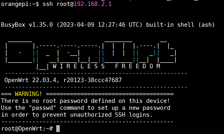
If the computer is installed with Windows system, you can log in by referring to the method introduced in the section of SSH remote login to the development board under Windows.

Log in to the LuCI management interface
|
Please note that the OpenWRT system configures the network port near the Type-C power port as a WAN port by default, and the network port near the HDMI port as a LAN port by default.  |
- First connect the LAN port of the board to the network port of the computer with a network cable, so that the network port of the computer can obtain an IP address through DHCP
- The LAN port IP of the default board is set to 192.168.2.1, so the computer can obtain the IP address starting with 192.168.2 at this time
- Enter the IP address 192.168.2.1 in the browser on the computer to log in to the LuCI interface

The OpenWrt system does not set a password by default, so just click the login button. After successful login, the interface is displayed as shown in the figure below
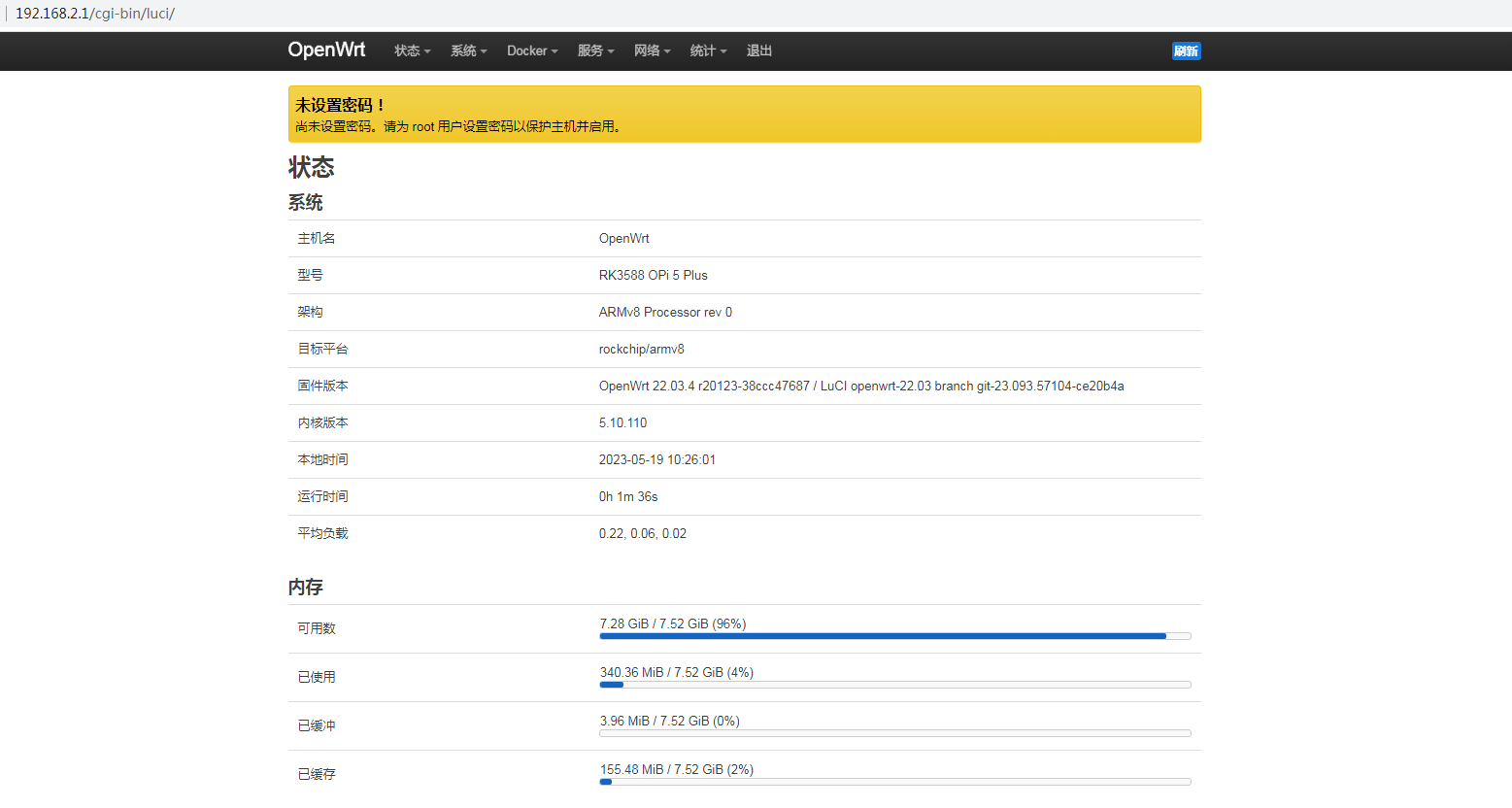

Log in to the terminal through the LuCI management interface
|
Please note that the OpenWRT system configures the network port near the Type-C power port as a WAN port by default, and the network port near the HDMI port as a LAN port by default. |
- First connect the LAN port of the board to the network port of the computer with a network cable, so that the network port of the computer can obtain an IP address through DHCP
- The LAN port IP of the default board is set to 192.168.2.1, so the computer can obtain the IP address starting with 192.168.2 at this time
- Enter the IP address 192.168.2.1 in the browser on the computer to log in to the LuCI interface
- Select "Terminal" in the "Service" column of the navigation bar and click to enter

At this time, the terminal interface is as shown in the figure below
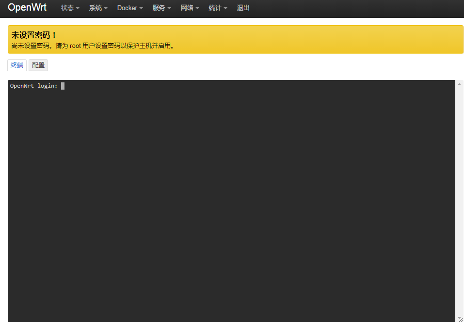
Enter the user name root to log in
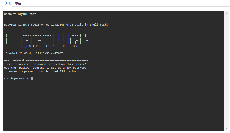


Use IP address + port number to log in to the terminal
|
Please note that the OpenWRT system configures the network port near the Type-C power port as a WAN port by default, and the network port near the HDMI port as a LAN port by default. |
- First connect the LAN port of the board to the network port of the computer with a network cable, so that the network port of the computer can obtain an IP address through DHCP
- The LAN port IP of the default board is set to 192.168.2.1, so the computer can obtain the IP address starting with 192.168.2 at this time
- Then enter 192.168.2.1:7681 in the browser to log in to the OpenWRT terminal

How to modify the IP address of the LAN port through the command line
- In the OpenWrt system, a command line tool uci is provided, which can easily modify, add, delete and read the content in the configuration file. For details, please refer to the official document
- First use the following command to obtain the network configuration, the corresponding configuration file is /etc/config/network, you can see that the value of network.lan.ipaddr is 192.168.2.1
root@OpenWrt:~# uci show network
...
network.lan=interface
network.lan.device='br-lan'
network.lan.proto='static'
network.lan.ipaddr='192.168.2.1'
network.lan.netmask='255.255.255.0'
network.lan.ip6assign='60'
.…
- Then enter the following command to modify the item network.lan.ipaddr
|
root@OpenWrt:~# uci set network.lan.ipaddr='192.168.100.1' |
- Then enter the following command to complete the submission, that is, write to the configuration file
- option device 'br-lan'
- option proto 'static'
- option netmask '255.255.255.0'
- option ip6assign '60'
- option ipaddr '192.168.100.1'
|
root@OpenWrt:~# uci commit |
If the IP address in red font is consistent with the one to be set, it means that the modification is successful
|
root@OpenWrt:~# cat /etc/config/network ... config interface 'lan' ... |
- Restart the network through ubus, please refer to the official document for the usage instructions of ubus
|
root@OpenWrt:~# ubus call network restart |
At this point, enter the command and you can see that the IP of the LAN port is 192.168.100.1
root@OpenWrt:~# ifconfig br-lan
br-lan Link encap:Ethernet HWaddr FE:55:13:A3:EF:E7
inet addr:192.168.100.1 Bcast:192.168.100.255 Mask:255.255.255.0
inet6 addr: fd60:c4cd:1033::1/60 Scope:Global
UP BROADCAST MULTICAST MTU:1500 Metric:1
RX packets:0 errors:0 dropped:0 overruns:0 frame:0
TX packets:3 errors:0 dropped:0 overruns:0 carrier:0
collisions:0 txqueuelen:1000
RX bytes:0 (0.0 B) TX bytes:370 (370.0 B)
How to modify the root password
Modify via command line
- First enter passwd root on the command line of the system, and the following prompt message will appear. At this time, you can enter the password you want to set, and press the Enter key to confirm
root@OpenWrt:/# passwd root
Enter new UNIX password:
- Then you will be prompted to re-enter the password. At this time, enter the password again to confirm and press Enter
|
Retype password: |
- The display of successful modification is as follows
|
passwd: password for root changed by root |
Modify through the LuCI management interface
First refer to the login LuCI management interface to enter the OpenWRT management interface
Then follow the steps below to change the password
Find the "System" option in the navigation bar and click
In the column options below the system, select "Management Rights" and click
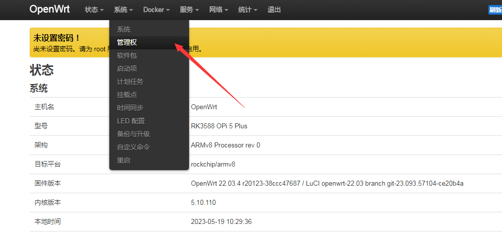
Select the "Router Password" option on the Tab page
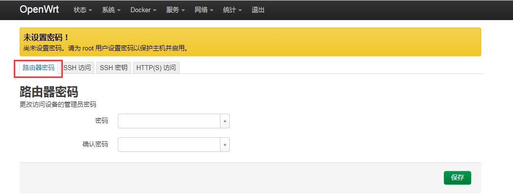
Modify and save the router password
a. Enter the password you set in the "Password" and "Confirm Password" dialog boxes (if you are not sure whether the password is entered correctly, you can click the "*" icon behind the dialog box to display the input characters)
b. Click "Save" to save the newly modified password
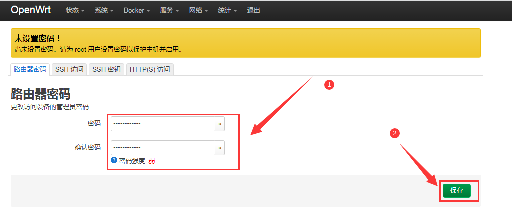


|
Note: In the "Password" and "Confirm Password" dialog boxes, the passwords entered twice must be consistent. |
After the password is changed successfully, a pop-up box will pop up saying "The system password has been changed successfully". At this time, a password is required to log in to OpenWRT
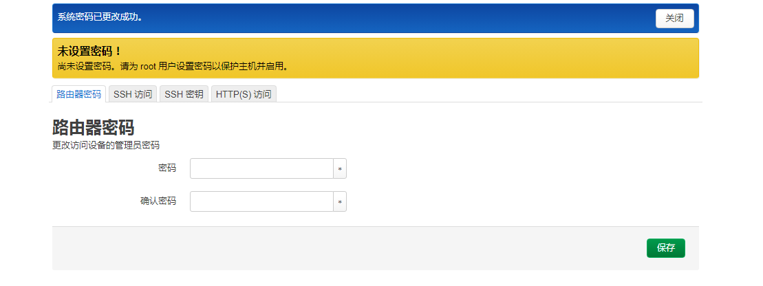

USB interface test
Mount the USB storage device under the command line
- First insert the U disk into the USB interface of the Orange Pi development board
- Execute the following command, if you can see the output of sdX, it means that the U disk is recognized successfully
root@OpenWrt:~# cat /proc/partitions | grep "sd*"
majorminor #blocksname
8015126528 sda
- Use the mount command to mount the U disk to /mnt, and then you can view the files in the U disk
|
root@OpenWrt:~# mount /dev/sda /mnt/ root@OpenWrt:~# ls /mnt/ test.txt |
- After mounting, you can view the capacity usage and mount point of the U disk through the df -h command
|
root@OpenWrt:~# df -h | grep "sd" /dev/sda14.4G187.2M14.2G1% /mnt |
Mount the USB storage device on the LuCI management interface
First connect the U disk (or other storage device) to the development board via USB2.0
Then follow the login LuCI management interface to enter the LuCI management interface
Then in the LuCI management interface, click "System -> Mount Point" to enter the configuration interface of the mount point
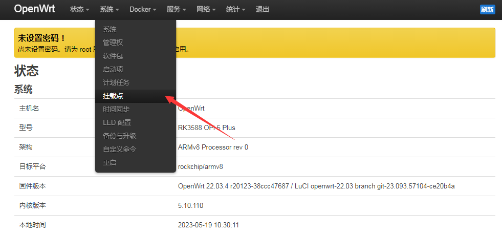
Then follow the steps below to add a mount point
Find "Mount Point" at the bottom of the mount point global setting interface
Under the mount point, select the "Add" button and click Enter
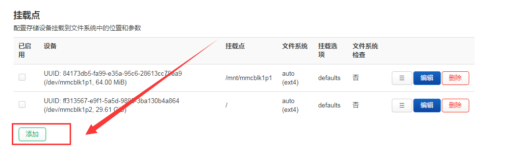
Then the following pop-up interface will pop up
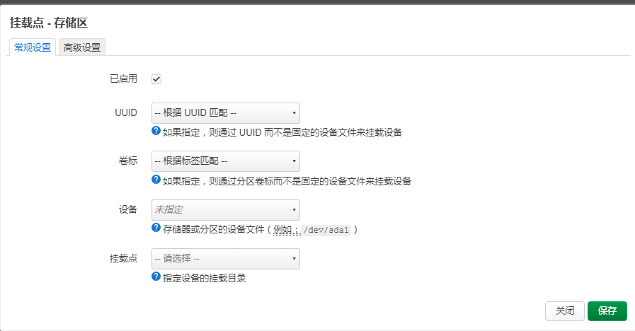
Then you can start to mount the storage device
a) Check "Enabled"
b) Select the actual connected device /dev/sda in the UUID column of general settings (choose according to your own device)
c) Select "Custom" in the mount point column, and fill in the target directory to be mounted. Here, take the /mnt directory as an example, and press Enter to confirm
d) Then click the "Save" button in the lower right corner
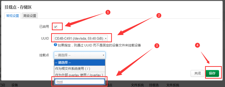


- Then you will return to the mount point global settings page, click "Save and Apply" in the lower left corner of the page to make the mount point take effect

- After saving, you can see the "mounted file system", the storage device has been mounted successfully

How to use E-Key PCIe wireless network card
- The PCIe wireless network card models currently compatible with the OpenWRT image are as follows:
serial number model Physical picture Supported OS 1 AX200 (PCIE+USB接口)
Debian Ubuntu
OpenWRT
OPi OS Arch
2 AX210 (PCIE+USB接口)
Debian Ubuntu
OpenWRT
OPi OS Arch
3 RTL8852BE (PCIE+USB接口)
Debian Ubuntu
Not Supported OpenWRT
Android12
OPi OS Arch
OPi OS Droid
How to create WIFI hotspot
|
Note that AX200 and AX210 currently only support hotspots in the 2.4G frequency band. In the 5G frequency band mode, there will be an error that the modified configuration of the wireless network card cannot be applied. |
First insert the PCIe wireless network card into the M.2 E-KEY port of the development board, and then connect the Type-C power supply to power up the development board.
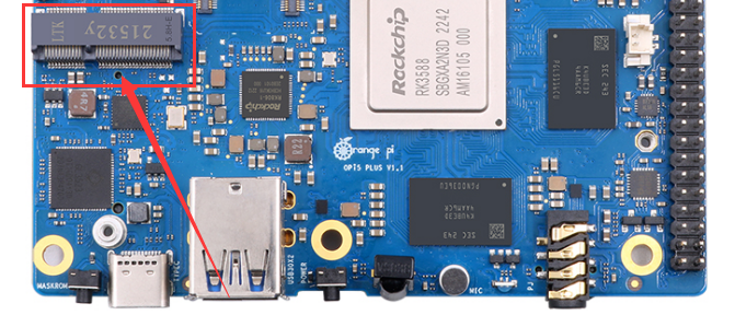
After the system startup is complete, click Network -> Wireless to enter the wireless WiFi configuration interface.
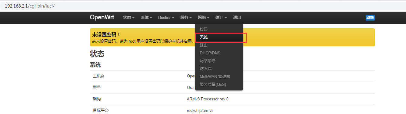
The default wireless configuration of the OpenWRT system is Master mode. Here, for the convenience of the next operation, we will remove the default wireless connection.
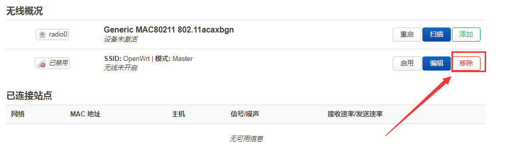
Then click Save in the lower right corner of the page to make the configuration take effect.
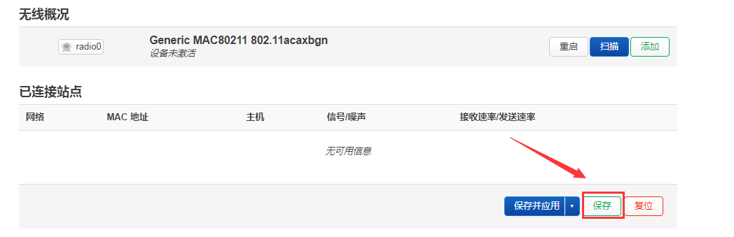
Then click the Add button on the right.
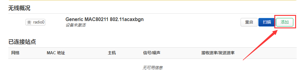
In the pop-up tab page Device Configuration, we set the parameters as shown in the figure below.
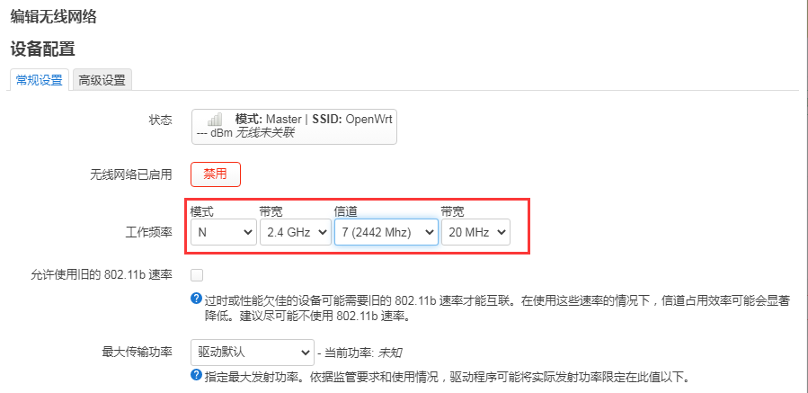
Then in Interface Configuration -> General Settings, set the mode to Access Point AP, set the ESSID (wireless network name) to OpenWrt, and specify the network as lan
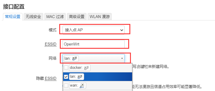
Then in Interface Configuration -> Wireless Security, select WPA2-PSK as the encryption algorithm; set the key (wireless password) to password
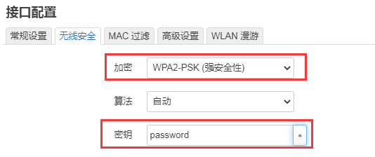
After the above settings are completed, click Save in the lower right corner of the page, and then exit the tab page
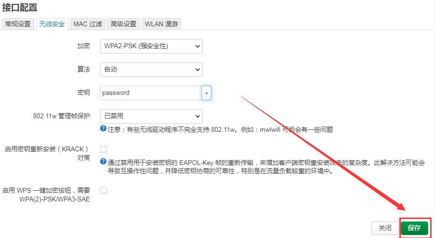
Then click Save and Apply in the lower right corner of the page and wait for the configuration to be applied.
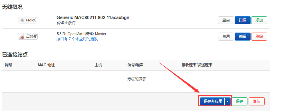
The display interface of successfully creating a hotspot is shown in the figure below
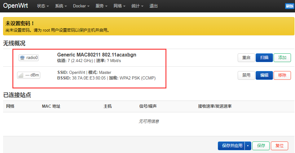
Then use the mobile phone or computer to search for the WiFi corresponding to the SSID to connect. After the connection is successful, as shown in the figure below
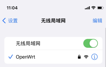


How to connect to WIFI hotspot
Insert the PCIe wireless network card into the M.2 E-KEY port of the development board, and then connect the Type-C power supply to power the development board.
After the system startup is complete, click Network -> Wireless to enter the configuration wireless WiFi interface.
The default wireless configuration of the OpenWRT system is Master mode. Here, for the convenience of the next operation, we will remove the default wireless connection.
Then click Save in the lower right corner of the page to make the configuration take effect.
Then click the Scan button to scan the surrounding WiFi hotspots.
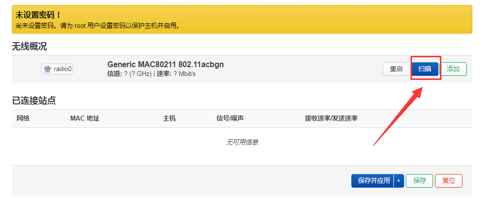
Then the following window will pop up to display the available WiFi hotspots. At this time, click the Join Network button on the right side of the WiFi hotspot you want to connect to connect to the WiFi hotspot.
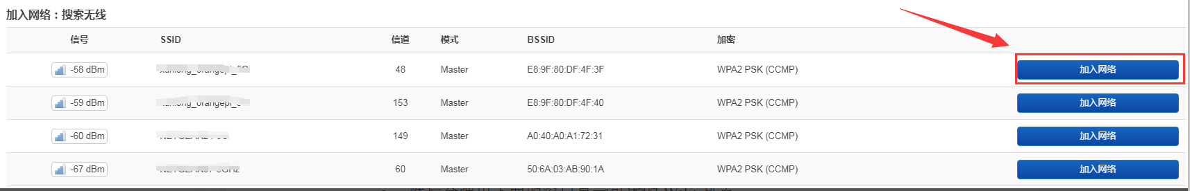
Then an interface for connecting to a WiFi hotspot will pop up. We enter the password of the hotspot as shown in the figure below, and then click the Submit button.
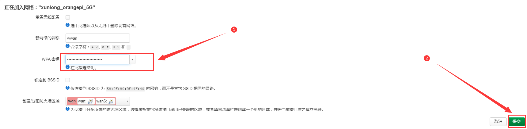
Then the following interface will pop up, click the Save button in the lower right corner.
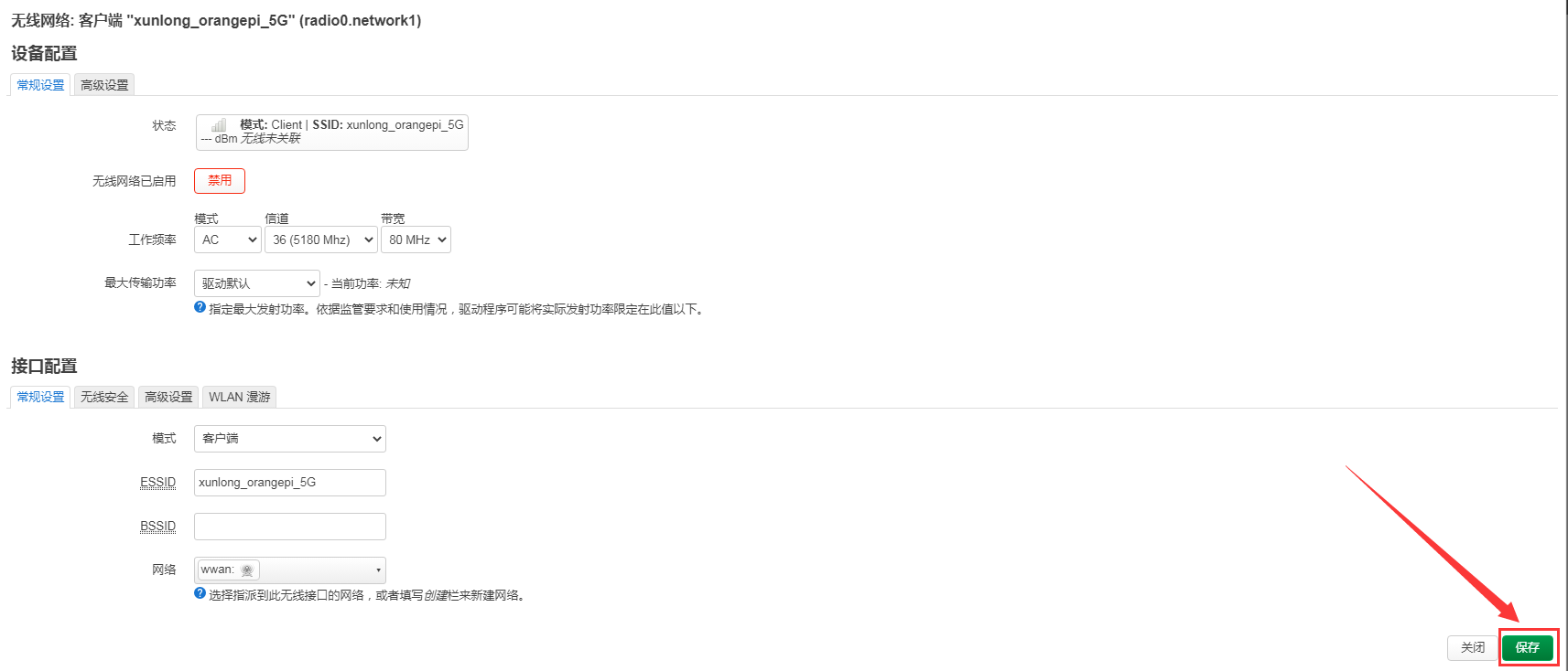
Finally, you will return to the main interface of wireless configuration, click Save and Apply and wait for the configuration to be applied.
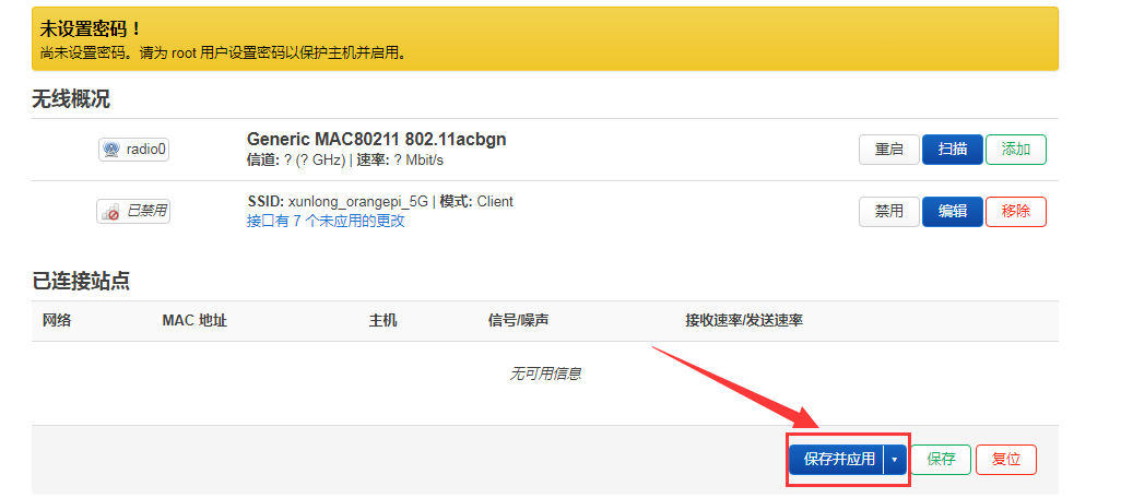
After successfully connecting to the WiFi hotspot, the interface is displayed as shown in the figure below.
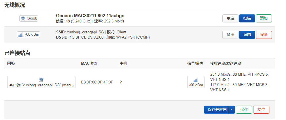


Installing packages via the command line
Install via opkg in the terminal
- Update the list of available packages
root@OpenWrt:/# opkg update
- Get the software list
|
root@OpenWrt:/# opkg list |
- Install the specified package
|
root@OpenWrt:/# opkg install <package name> |
- Check the installed software
|
root@OpenWrt:/# opkg list-installed |
- Uninstall the software
|
root@OpenWrt:/# opkg remove <package name> |
OpenWRT management interface installation software package
|
If you need to add new software packages, you can install them through the OpenWRT management interface. |
View the list of available software packages in the system
First enter the package management page
a. Find the "System" option in the navigation bar and click to enter
b. In the vertical column options below the system, select "software package" and click to enter

Then the main page of the software package will appear, as shown in the figure below, to obtain the list of available software
a. In the "Operation" option of the software package, click "Update List" to get the list of available software packages
b. On the Tab page, click "Available" to view the currently available software packages
c. View the number of currently available packages
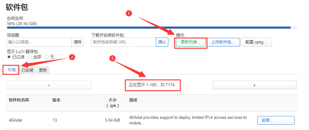

Example of installing software packages
Take the installation package "luci-app-acl" as an example
In the OpenWRT software package management interface, click the filter dialog box and enter "luci-app-acl"
In the list of software packages, you can see the version, package size and description information of the "luci-app-acl" software package, and then click the "Install" button
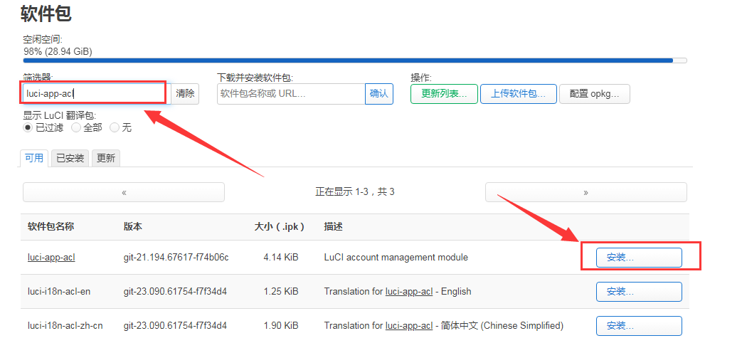
Then the following pop-up window will appear, click "Install"
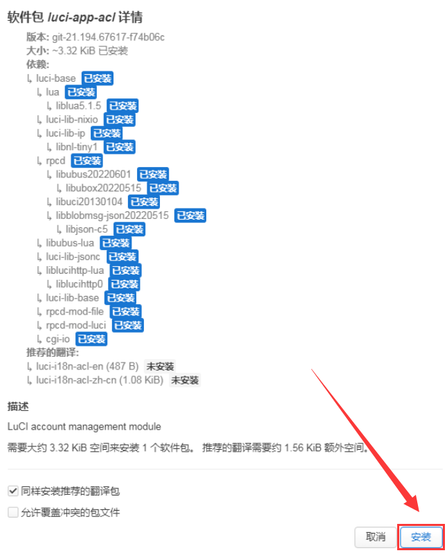
Then wait for the installation to complete
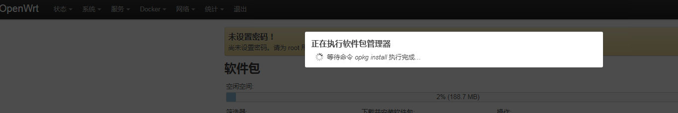
The display after the installation is complete is as follows
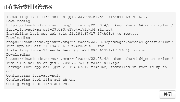
Check whether the software package is installed successfully
a. In the OpenWRT software package management interface, click the filter dialog box and enter "luci-app-acl"
b. Select and click "Available" on the Tab page
c. The "luci-app-acl" package will be displayed in the package list, and the update status will be "installed"
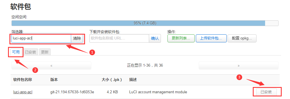


Remove package example
Take the removal of the package "luci-app-acl" as an example
In the OpenWRT software package management interface, click the filter dialog box and enter "luci-app-acl"
Select "Installed" on the Tab page to display the list of installed software packages
Click "Remove" on the right to remove the corresponding software package
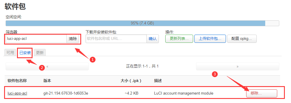
Then the following pop-up window will be displayed, click "Remove"
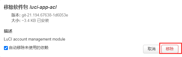
After the removal is successful, the display interface is as follows
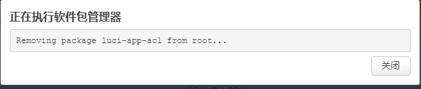
Check whether the software package is removed successfully
a. In the OpenWRT software package management interface, click the filter dialog box and enter "luci-app-acl"
b. Select and click "Installed" on the Tab page
c. The "luci-app-acl" package will not be displayed in the package list, and the "luci-app-acl" package has been removed successfully
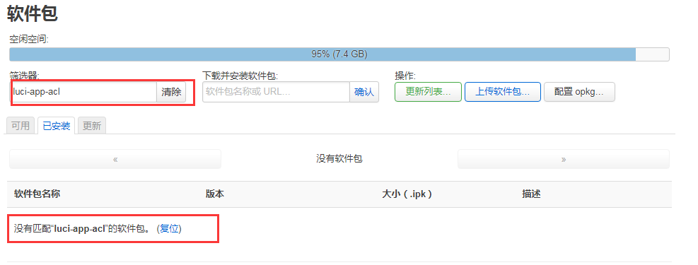


|
There are mainly two software options for OpenWRT LAN file sharing, Samba and NFS. The compatibility of the Samba system is better, while the performance of NFS is superior. For users who need to use Windows devices, it is recommended to choose Samba. |
Enter the management page of the Samba network share
Find the "Service" option in the navigation bar and click to enter
In the vertical column options below the service, select "network sharing" and click to enter
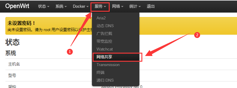
Select the interface that the Samba service needs to monitor
Select "General Settings" in the navigation bar of network sharing and click to enter
The interface is specified according to actual needs. If you want to access through the "wan port", set it to "wan"
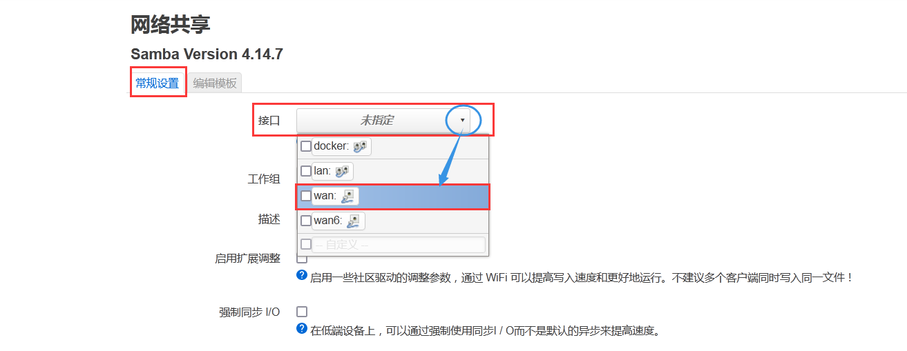
Set the shared directory of the network share
a. In the "Shared Directory" of the "General Settings" of the network share, click "Add" the shared directory address
b. Enter the name of the shared folder as "mmt" under the name
c. Under the path of the shared directory, choose to set the shared directory location "/mnt"
d. Check "Browseable" and "Run anonymous user"
e. Click "Save and Apply" to save the configuration
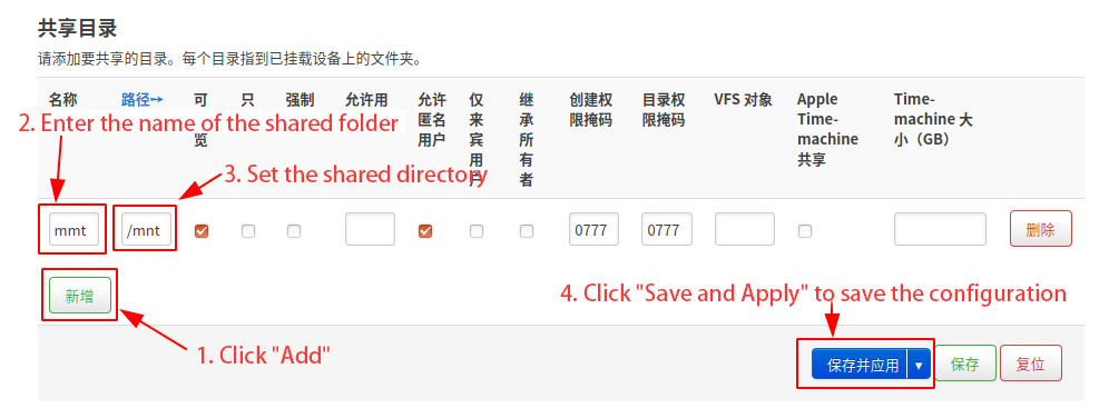
window10 starts network discovery and sharing
Note: To access Samba under the Windows 10 system, you need to confirm whether Windows 10 has enabled network discovery and sharing for sharing. If it is not enabled, perform the following settings first.
Enable Samba v1/v2 access
a) Enter the "Control Panel" of Windows 10
b) Click "Programs" on the left navigation bar of the control panel
c) Select "Turn Windows features on or off" in Programs and Features
d) Check "SMB 1.0/CIFS file sharing support" in the pop-up box of enabling or disabling Windows functions
e) Click "OK" to configure the application
Turn on the network discovery of Windows 10
a) Enter the "Control Panel" of Windows 10
b) Select "Network and Internet" in the Control Panel
c) Then open "Network and Sharing Center"
d) Click | "Advanced Sharing Settings"
e) Turn on "Enable Network Discovery" and "Enable File and Printer Sharing"
f) Click "Save Changes" to save the Windows 10 network discovery configuration


- After the setting is completed, enter \\OpenWrt in the address bar of the resource manager to access the shared directory, the user name is root, and the password is the password set by the development board host

Zerotier Instructions
|
The OpenWRT system has pre-installed the zerotier client. After creating a virtual LAN on the zerotier official website, the client can directly join it through the Network ID. The specific operation is as shown below. |
Log in to zerotier official website https://my.zerotier.com/network, register and log in and click Network->Create A Network to create a virtual local area network
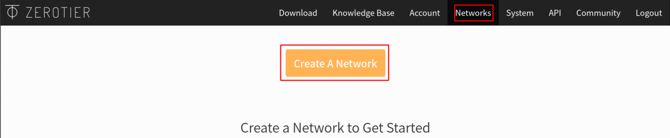
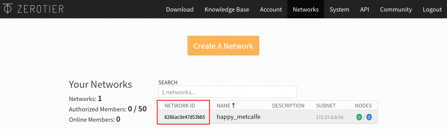
Click to enter the network console page, you can set the privacy option to public, so that the added network nodes do not need to be verified
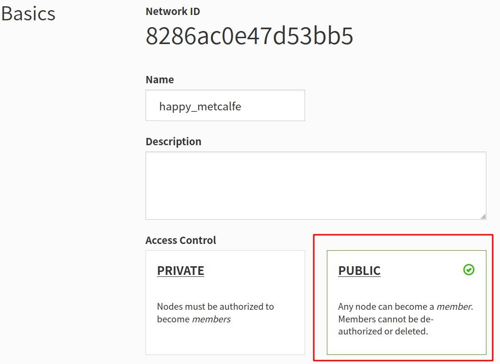
The following automatically assigns the address Here you can choose the network segment yourself, here is 172.27.*.*
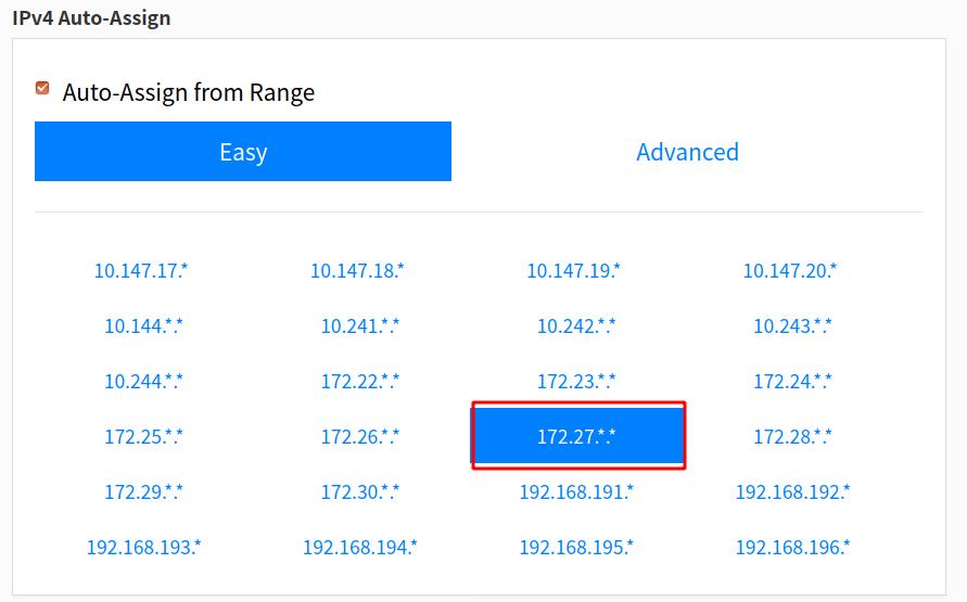
Enter the following command in the OpenWRT terminal to join the virtual LAN created above, where 8286ac0e47d53bb5 is the Network ID of the virtual LAN created above


|
root@OpenWrt:/# zerotier-one -d #Start the zerotier client root@OpenWrt:/# zerotier-cli join 8286ac0e47d53bb5 #join the network |
- Enter ifconfig in the terminal and you can see that there is already a new ztks54inm2 device with an IP address of 172.27.214.213
- inet addr:172.27.214.213 Bcast:172.27.255.255 Mask:255.255.0.0
- inet6 addr: fe80::e82f:d0ff:fe5a:867e/64 Scope:Link
- UP BROADCAST RUNNING MULTICAST MTU:2800 Metric:1
- RX packets:18 errors:0 dropped:0 overruns:0 frame:0
- TX packets:48 errors:0 dropped:0 overruns:0 carrier:0
- collisions:0 txqueuelen:1000
|
root@OpenWrt:/# ifconfig ztks54inm2 Link encap:Ethernet HWaddr F6:4E:DE:BF:D8:52 RX bytes:1720 (1.6 KiB) TX byte81 (8.2 KiB) |
- Install the zerotier client on another device (Ubuntu18.04 is used as an example here), execute the following command to install, and restart the computer after the installation is complete
|
test@ubuntu:~$ curl -s https://install.zerotier.com | sudo bash |
- After restarting, join the virtual LAN according to the Network ID, and you can also see that the ip address assigned by zerotier has been obtained. At this time, the Ubuntu PC and OrangePi R1 Plus LTS are in the same LAN, and the two can communicate freely
- inet 172.27.47.214 netmask 255.255.0.0 broadcast 172.27.255.255
- inet6 fe80::5ce1:85ff:fe2b:6918 prefixlen 64 scopeid 0x20<link>
- ether f6:fd:87:68:12:cf txqueuelen 1000 (ethernet)
- RX packets 0 bytes 0 (0.0 B)
- RX errors 0 dropped 0 overruns 0 frame 0
- TX packets 46 bytes 10006 (10.0 KB)
- TX errors 0 dropped 0 overruns 0 carrier 0 collisions 0
|
test@ubuntu:~$ sudo zerotier-cli join 8286ac0e47d53bb5 test@ubuntu:~$ ifconfig ztks54inm2: flags=4163<UP,BROADCAST,RUNNING,MULTICAST> mtu 2800 |
- Test whether the two terminals can communicate
|
root@OpenWrt:/# ping 172.27.47.214 -I ztks54inm2 PING 172.27.47.214 (172.27.47.214): 56 data bytes 64 bytes from 172.27.47.214: seq=0 ttl=64 time=1.209 ms 64 bytes from 172.27.47.214: seq=1 ttl=64 time=1.136 ms 64 bytes from 172.27.47.214: seq=2 ttl=64 time=1.203 ms 64 bytes from 172.27.47.214: seq=3 ttl=64 time=1.235 ms ^C --- 172.27.47.214 ping statistics --- 4 packets transmitted, 4 packets received, 0% packet loss round-trip min/avg/max = 1.136/1.195/1.235 ms |
- other common commands of zerotier
|
root@OpenWrt:/# zerotier-one -d #Start the zerotier client root@OpenWrt:/# zerotier-cli status #Get address and service status root@OpenWrt:/# zerotier-cli join # Network ID #join the network root@OpenWrt:/# zerotier-cli leave # Network ID #leave the network root@OpenWrt:/# zerotier-cli listnetworks #list networks OPENWRT_DEVICE_REVISION="v0" OPENWRT_RELEASE="OpenWrt 22.03.4 r20123-38ccc47687" |
Compilation method of OpenWRT source code
Download OpenWRT source code
- First execute the following command to download the openwrt-22.03 branch code
test@test:~$ sudo apt update
test@test:~$ sudo apt install -y git
test@test:~$ git clone https://github.com/orangepi-xunlong/openwrt.git -b openwrt-22.03
- After the OpenWRT code is downloaded, the following files and folders will be included
|
test@test:~/openwrt$ ls BSDmakefile Config.in include Makefile README.md scripts toolchain Config feeds.conf.default LICENSE package rules.mk target tools |
Compile OpenWRT source code
First install the following dependent packages (currently only tested on Ubuntu 20.04 to compile the following dependent packages, if you compile on other versions of the system, please install the dependent packages by yourself according to the error message)
- Method 1: The command to install dependent packages using a > script is as follows:
test@test:~/openwrt$ sudo ./install_dep.sh
- Method 2: Install the dependency package directly using the following command
test@test:~/openwrt$ sudo apt update
test@test:~/openwrt$ sudo apt install -y ack antlr3 asciidoc autoconf \
automake autopoint binutils bison build-essential \
bzip2 ccache cmake cpio curl device-tree-compiler fastjar \
flex gawk gettext gcc-multilib g++-multilib git gperf haveged \
help2man intltool libc6-dev-i386 libelf-dev libglib2.0-dev \
libgmp3-dev libltdl-dev libmpc-dev libmpfr-dev \
libncurses5-dev \libncursesw5-dev libreadline-dev libssl-dev \
libtool lrzsz mkisofs msmtp nano ninja-build p7zip p7zip-full \
patch pkgconf python2.7 python3 python3-pyelftools \
libpython3-dev qemu-utils rsync scons squashfs-tools \
subversion swig texinfo uglifyjs upx-ucl unzip \
vim wget xmlto xxd zlib1g-dev
- Then execute ./scripts/feeds update -a and ./scripts/feeds install -a to download dependent packages
|
test@test:~/openwrt$ ./scripts/feeds update -a test@test:~/openwrt$ ./scripts/feeds install -a |
Then choose to use the configuration file of OrangePi 5 Plus
- Compile the image that supports TF card, eMMC, and NVMe startup, > and select the following configuration
test@test:~/openwrt$ cp configs/orangepi-5-plus-rk3588_defconfig .config
- Compile the image that supports SPIFlash startup, and select the > following configuration
test@test:~/openwrt$ cp configs/orangepi-5-plus-rk3588-spi_defconfig .config
- Then execute the following command to make the configuration take effect
|
test@test:~/openwrt$ make defconfig |
- Execute the following command to start compiling the openwrt source code
|
test@test:~/openwrt$ make V=s |
- After the compilation is complete, the path where the image is generated is:
|
test@test:~/openwrt$ tree -L 1 bin/targets/rockchip/armv8/ bin/targets/rockchip/armv8/ ├── config.buildinfo ├── feeds.buildinfo ├── openwrt-rockchip-armv8-xunlong_orangepi-5-plus-ext4-sysupgrade.img.gz ├── openwrt-rockchip-armv8-xunlong_orangepi-5-plus.manifest ├── openwrt-rockchip-armv8-xunlong_orangepi-5-plus-squashfs-sysupgrade.img.gz ├── packages ├── profiles.json ├── sha256sums └── version.buildinfo
|
Instructions for using the Android 12 system
Supported Android versions
| Android version | kernel version |
| Android 12 | Linux5.10 |
| Android 12 Box | Linux5.10 |
Android function adaptation
| Function | Android 12 | Android12 Box |
| HDMI TX1 Display - 1080p | OK | OK |
| HDMI TX1 Display - 4K 120HZ | OK | OK |
| HDMI TX1 Display - 8K 60HZ | OK | OK |
| HDMI TX1 Audio | OK | OK |
| HDMI TX2 Display - 1080p | OK | OK |
| HDMI TX2 Display - 4K 120HZ | OK | OK |
| HDMI TX2 Display - 8K 60HZ | OK | OK |
| HDMI TX2 Audio | OK | OK |
| HDMI RX display | OK | OK |
| HDMI RX Audio | OK | OK |
| USB2.0X2 | OK | OK |
| 2.5G PCIe network port X2 | OK | OK |
| 2.5G PCIe network port light | OK | OK |
| Debug serial port | OK | OK |
| RTC | OK | OK |
| FAN interface | OK | OK |
| eMMC extension interface | OK | OK |
| AP6275P-WIFI | OK | OK |
| AP6275P-BT | OK | OK |
| AX200-WIFI | NO | NO |
| AX200-BT | NO | NO |
| AX210-WIFI | NO | NO |
| AX210-BT | NO | NO |
| RTL8852BE-WIFI | OK | OK |
| RTL8852BE-BT | OK | OK |
| Recovery button | OK | OK |
| Type-C interface USB3.0 function | OK | OK |
| Type-C interface ADB function | OK | OK |
| Type-C interface DP display function | OK | OK |
| Type-C interface DP audio playback | OK | OK |
| USB3.0 Hub | OK | OK |
| switch button | OK | OK |
| infrared function | OK | OK |
| led light | OK | OK |
| Onboard MIC | OK | OK |
| headphone playback | OK | OK |
| headphone recording | OK | OK |
| SPK Horn | OK | OK |
| 40PIN GPIO | OK | OK |
| 40PIN I2C | OK | OK |
| 40PIN SPI | OK | OK |
| 40PIN UART | OK | OK |
| 40PIN PWM | OK | OK |
| TF card start | OK | OK |
| SPI Flash+NVME solid state boot | OK | OK |
| OV13850 camera | OK | OK |
| OV13855 camera | OK | OK |
| GPU | OK | OK |
| VPU | OK | OK |
| NPU | OK | OK |
| MIPI LCD display | OK | OK |
| MIPI LCD Touch | OK | OK |
| MIPI LCD backlight | OK | OK |
| HDMI CEC function | NO | OK |
How to use the USB wireless network card
- Currently, the USB wireless network card models compatible with the Android image are as follows:
Chip model Function VID&PID Adaptation RTL8723BU 2.4G WIFI+BT4.0 0bda:b720 Support WIFI and Bluetooth function, does not support hotspot RTL8811CU 2.4G +5G WIFI 0bda:c811 Support WIFI function and open hotspot
The pictures of the above two USB wireless network cards are as follows:
The picture of the RTL8723BU USB wireless network card module is as follows:
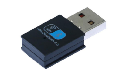
The picture of the RTL8811CU USB wireless network card module is as follows:
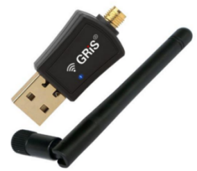
The test methods of the above two types of USB wireless network cards are the same. First, the USB network card needs to be inserted into the USB interface of the development board.
Then, for the connection and test method of WIFI, please refer to the section of WIFI connection test method
For the Bluetooth test, please refer to the content of the Bluetooth test method


M.2 How to use E-Key PCIe WIFI6+Bluetooth module
- The PCIe wireless network card models currently compatible with Android 12 are as follows:
serial number model Physical picture 1 RTL8852BE (PCIE+USB interface)
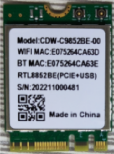

Pay attention to RTL8852BE, please do not buy the module shown in the figure below, there will be problems after testing.
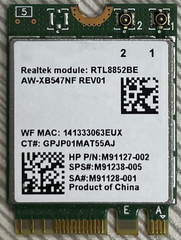

First insert the PCIe wireless network card into the M.2 E-KEY interface of the development board and fix it

Then connect the power supply of the Type-C interface to the development board, and power on
After the system starts, please refer to the section of WIFI connection test method for WIFI connection and test method
For the Bluetooth test, please refer to the content of the Bluetooth test method

WIFI connection test method
|
First of all, please note that there is no WIFI module on the Orange Pi 5 Plus development board, and an external PCIe network card or USB network card is required to use the WIFI function. For instructions on using the external PCIe network card, please refer to the section on how to use the M.2 E-Key PCIe WIFI6+Bluetooth module. For instructions on using the external USB network card, please refer to the section on how to use the USB wireless network card. |
- First click to enter the Setting

- Then select Network & internet

- Then select Internet

- Then turn on the Wi-Fi switch

After turning on Wi-Fi, if everything is normal, you can scan to nearby Wi-Fi hotspots
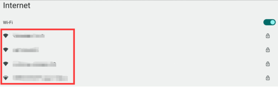
Then select the Wi-Fi you want to connect to, and the password input interface shown in the figure below will pop up
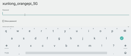
Then use the keyboard to enter the password corresponding to Wi-Fi, and then use the mouse to click the Enter button in the virtual keyboard to start connecting to Wi-Fi
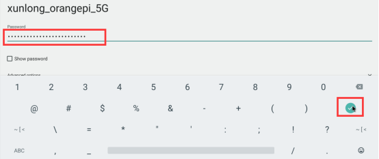
The display after successful Wi-Fi connection is shown in the figure below:
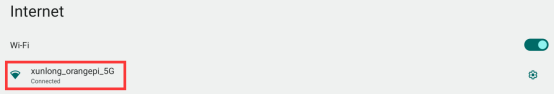


How to use Wi-Fi hotspot
First, please make sure that the Ethernet port is connected to the network cable and can access the Internet normally
Then select Settings
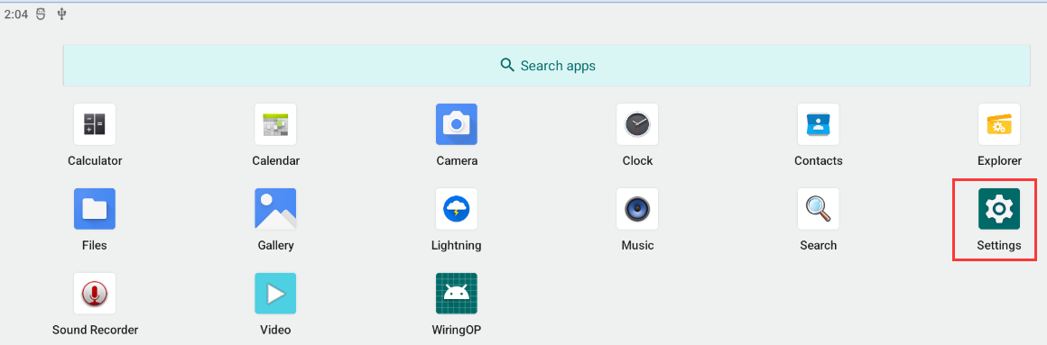
Then select Network & internet
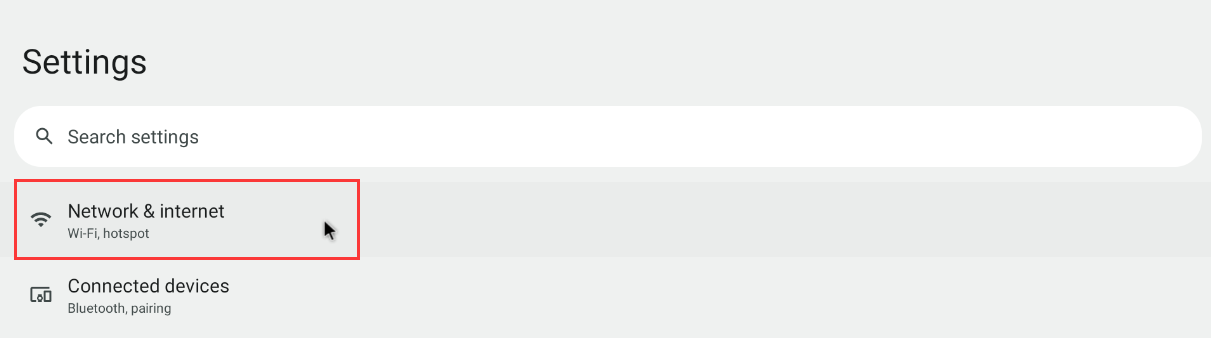
Then select Hotspot & tethering
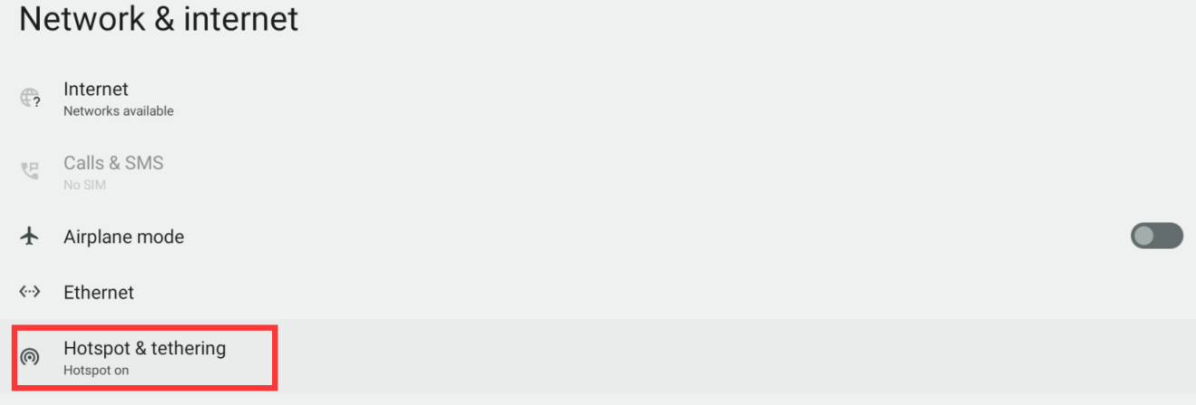
Then select Wi-Fi hotspot
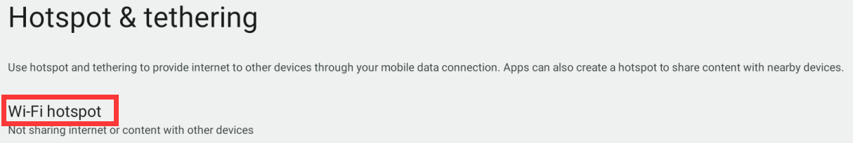
Then turn on the Wi-Fi hotspot, you can also see the name and password of the generated hotspot in the figure below, remember them, and use them when connecting to the hotspot (if you need to modify the name and password of the hotspot, you need to turn off the Wi-Fi first -Fi hotspot before modification)
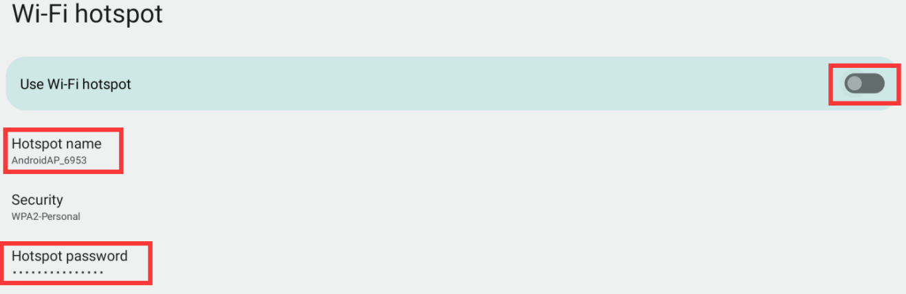
At this point, you can take out your mobile phone. If everything is normal, you can find the WIFI hotspot with the same name (here AndroidAP_6953) displayed under the Hotspot name in the above picture in the WI-FI list searched by the mobile phone. Then you can click AndroidAP_6953 to connect to the hotspot, and the password can be seen under the Hotspot password in the above picture


- After the connection is successful, it will be displayed as shown in the figure below (the interface of different mobile phones will be different, the specific interface is subject to the display of your mobile phone). At this point, you can open a webpage on your mobile phone to see if you can access the Internet. If you can open the webpage normally, it means that the WI-FI Hotspot of the development board can be used normally.

Bluetooth test method
|
Please note that there is no Bluetooth module on the Orange Pi 5 Plus development board, and an external PCIe network card with Bluetooth or a USB network card with Bluetooth is required to use the Bluetooth function. For instructions on using the external PCIe network card, please refer to the section on how to use the M.2 E-Key PCIe WIFI6+Bluetooth module. For instructions on using the external USB network card, please refer to the section on how to use the USB wireless network card. |
First click to enter the Setting
Then select Connected devices
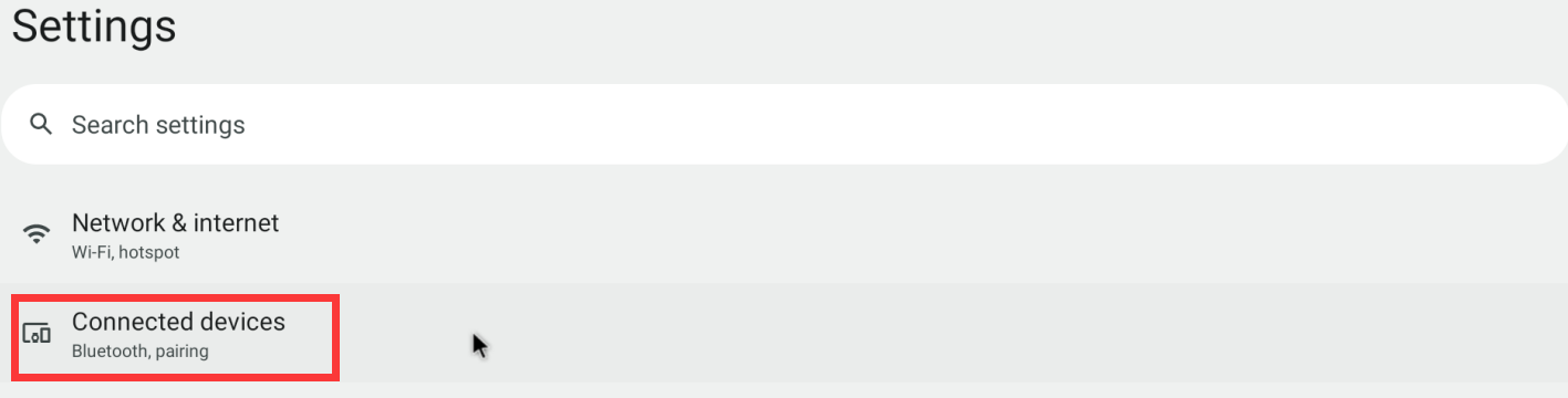
Then click Pair new device to turn on Bluetooth and start scanning the surrounding Bluetooth devices
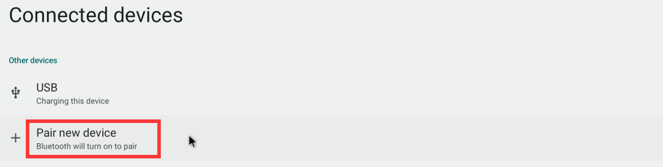
The searched Bluetooth devices will be displayed under Available devices

Then click the Bluetooth device you want to connect to start pairing. When the following interface pops up, please use the mouse to select the Pair option
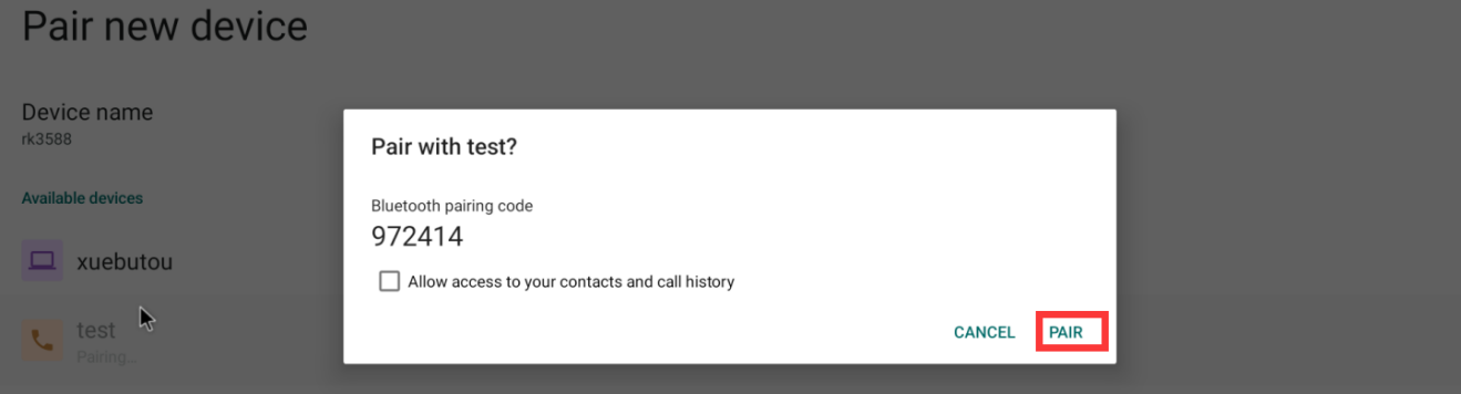
The test here is the configuration process of the development board and the Bluetooth of the Android mobile phone. At this time, the following confirmation interface will pop up on the mobile phone. After clicking the pairing button on the mobile phone, the pairing process will start
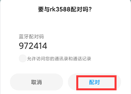
After the pairing is completed, you can see the paired Bluetooth device as shown in the figure below
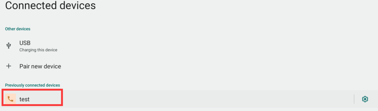
At this time, you can use the Bluetooth of your mobile phone to send a picture to the development board. After sending, you can see the following confirmation interface in the Android system of the development board, and then click Accept to start receiving the picture sent by the mobile phone.
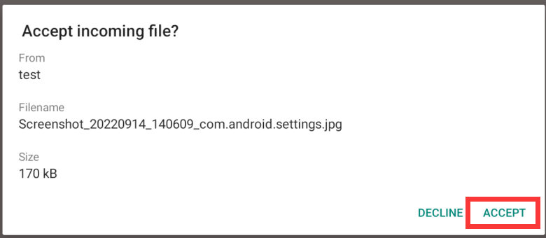
You can open the Download directory in the file manager to view the pictures received by the Android system Bluetooth of the development board


Test method of HDMI In
The location of the HDMI In interface on the development board is as follows:
Then use the HDMI to HDMI cable shown in the figure below to connect the HDMI output of other devices to the HDMI In interface of the development board
Make sure that the HDMI output of the device connected to the HDMI In interface is normal, and then open the HDMI In test APP
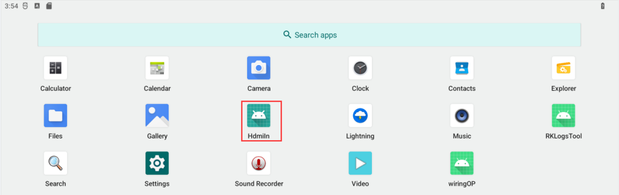
Then you can see the video input of HDMI In, and the audio input of HDMI In will also be output from the HDMI TX interface or headphone interface of the development board. The figure below shows the desktop of the Linux system of the OPi5 development board input through HDMI In.
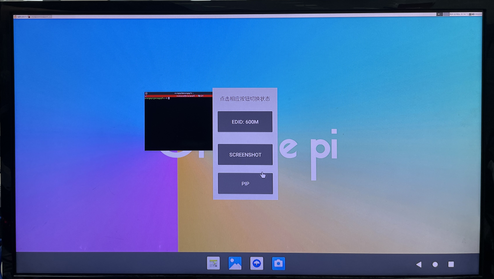


How to use 10.9.10.1 inch MIPI screen
|
Please make sure that the Android image used is the image of the following two versions: OrangePi5Plus_RK3588_Android12_lcd_v1.x.x.img OrangePi5Plus_RK3588_Android12_spi-nvme_lcd_v1.x.x.img |
The screen needs to be assembled first, please refer to the assembly method of the 10.1-inch MIPI screen
The interface position of the LCD on the development board is shown in the figure below:
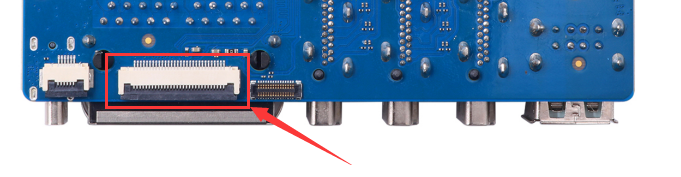
Note that the touch interface below is not for the LCD MIPI screen. It is currently a spare interface and cannot be used.
Connect the assembled screen to the LCD interface, connect the Type-C power supply to the board, and power on. After the system starts, you can see the screen display as shown in the figure below


OV13850 and OV13855 MIPI camera test method
Currently the development board supports two MIPI cameras, OV13850 and OV13855, the specific pictures are as follows:
OV13850 camera with 13 million MIPI interface
OV13855 camera with 13 million MIPI interface
The adapter boards and FPC cables used by the OV13850 and OV13855 cameras are the same, but the positions of the two cameras connected to the adapter boards are different. The FPC cable is shown in the figure below. Please note that the FPC cable has a direction. The end marked TO MB needs to be inserted into the camera interface of the development board, and the end marked TO CAMERA needs to be inserted into the camera adapter board.
There are a total of 3 camera interfaces on the camera adapter board, and only one can be used at a time, as shown in the figure below, of which:
No.1 port is connected to OV13850 camera
No.2 interface is connected to OV13855 camera
No.3 interface is not used, just ignore it

The location of the camera interface on the Orange Pi 5 Plus development board is shown in the figure below:

The method of inserting the camera into the CAM interface of the development board is as follows:
After connecting the camera to the development board, we can use the following method to test the camera:
Open the camera APP on the desktop
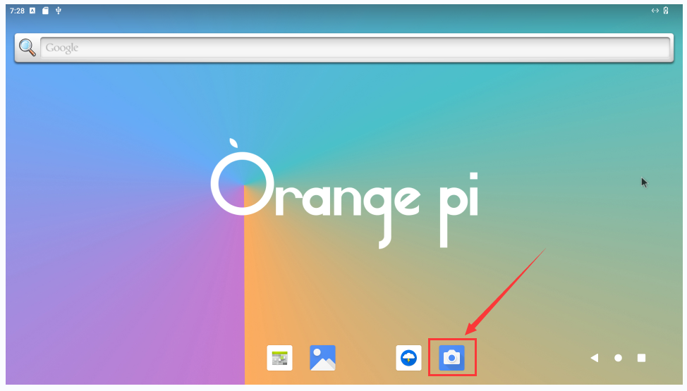
Then you can see the preview screen of the camera
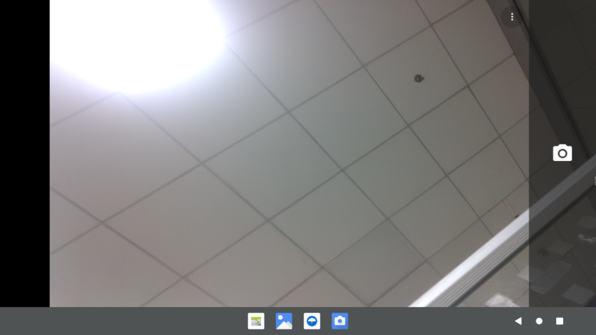
Press and hold the mouse in the area shown in the red box in the picture below of the camera APP and then drag to the right to call up the switching interface for taking pictures and recording
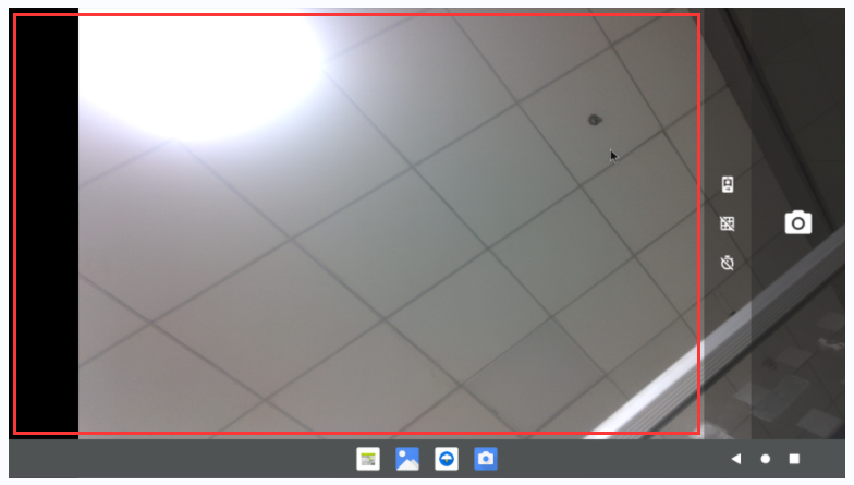
The switching interface of taking pictures and recording is as follows, click Video to switch to video recording mode
Click the position shown in the figure below to enter the camera setting interface
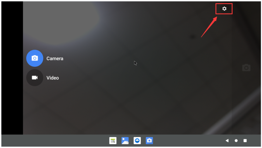
The setting interface of the camera is as follows:
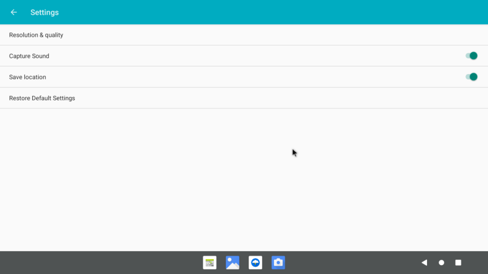


40pin interface GPIO, UART, SPI and PWM test
40pin GPIO port test
First click on the wiringOP icon to open the wiringOP APP
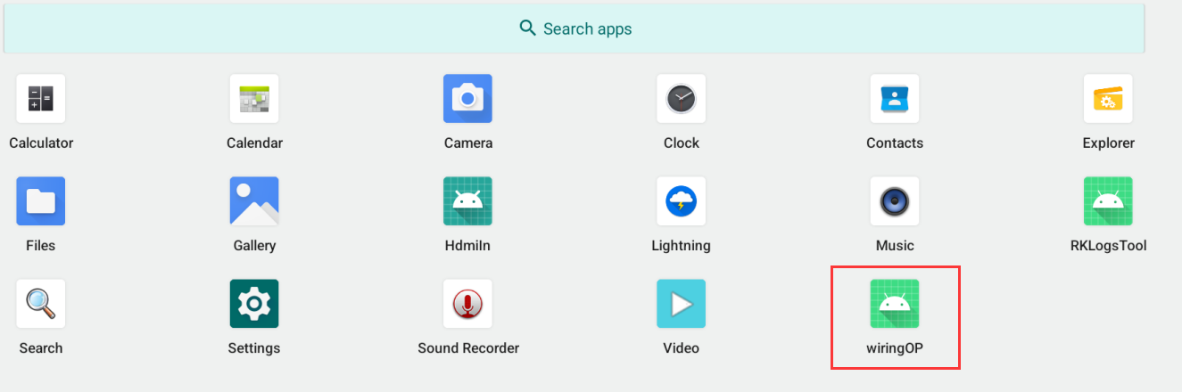
The main interface of wiringOP APP is displayed as shown in the figure below, and then click the GPIO_TEST button to open the GPIO test interface
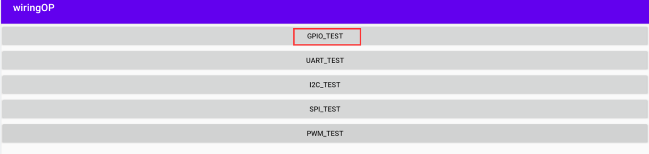
The GPIO test interface is shown in the figure below. The two rows of CheckBox buttons on the left are in one-to-one correspondence with the 26pin pins. When the CheckBox button is checked, the corresponding GPIO pin will be set to OUT mode, and the pin level will be set to high level; when the checkbox is unchecked, the GPIO pin level will be set to low level; When the GPIO READALL button is pressed, information such as the wPi number, GPIO mode, and pin level can be obtained.
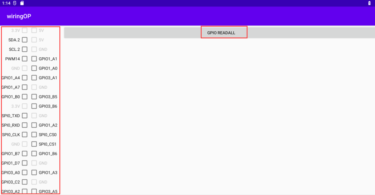
Then click the GPIO READALL button, the output information is as shown in the figure below:
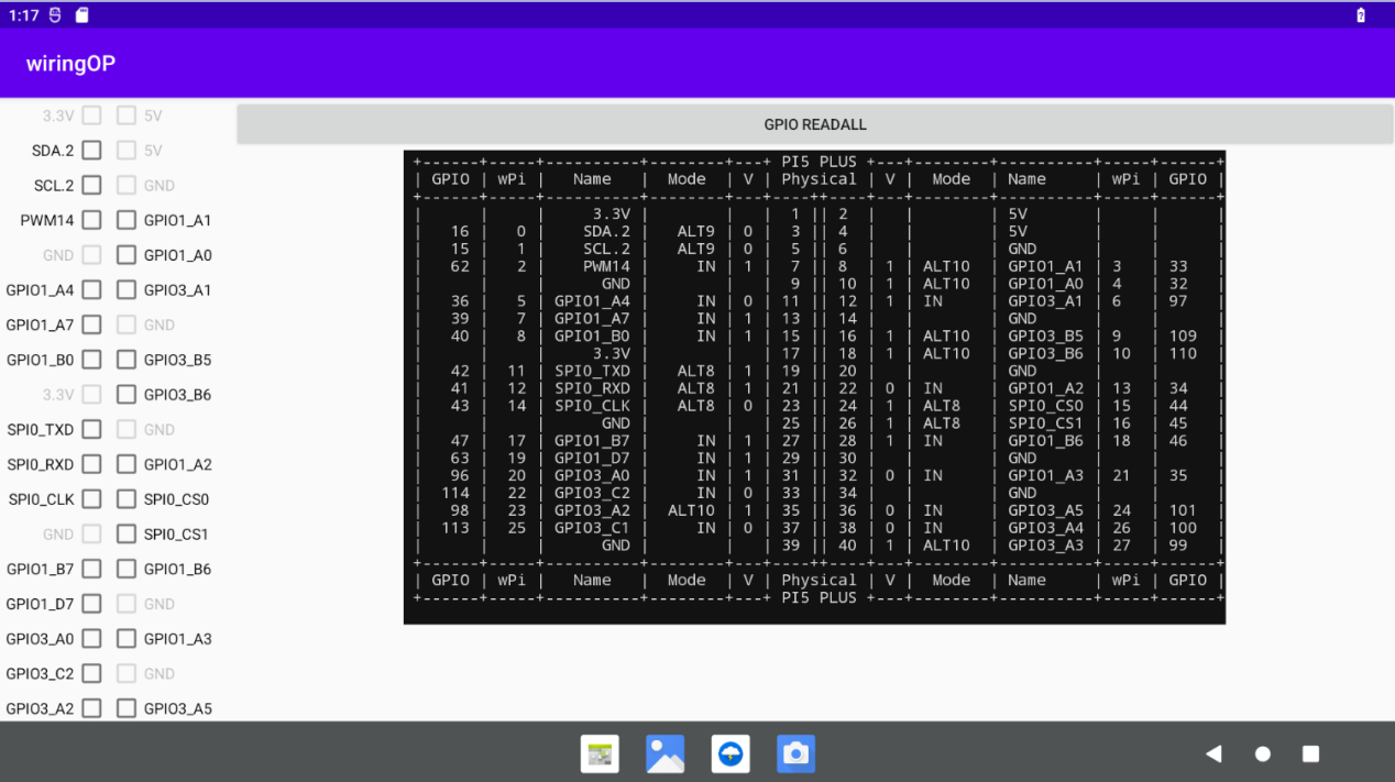
There are a total of 28 GPIO ports in the 40pins of the development board that can be used. The following uses pin 11—the corresponding GPIO is GPIO1_A4—the corresponding wPi serial number is 5—as an example to demonstrate how to set the high and low levels of the GPIO port. First click the CheckBox button corresponding to pin 11. When the button is selected, pin 11 will be set to high level. After setting, you can use a multimeter to measure the voltage value of the pin. If it is 3.3v, it means setting high level success
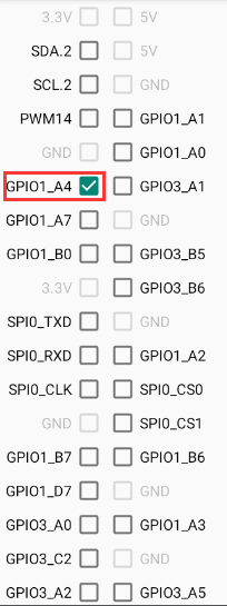
Then click the GPIO READALL button, you can see that the current pin 7 mode is OUT, and the pin level is high
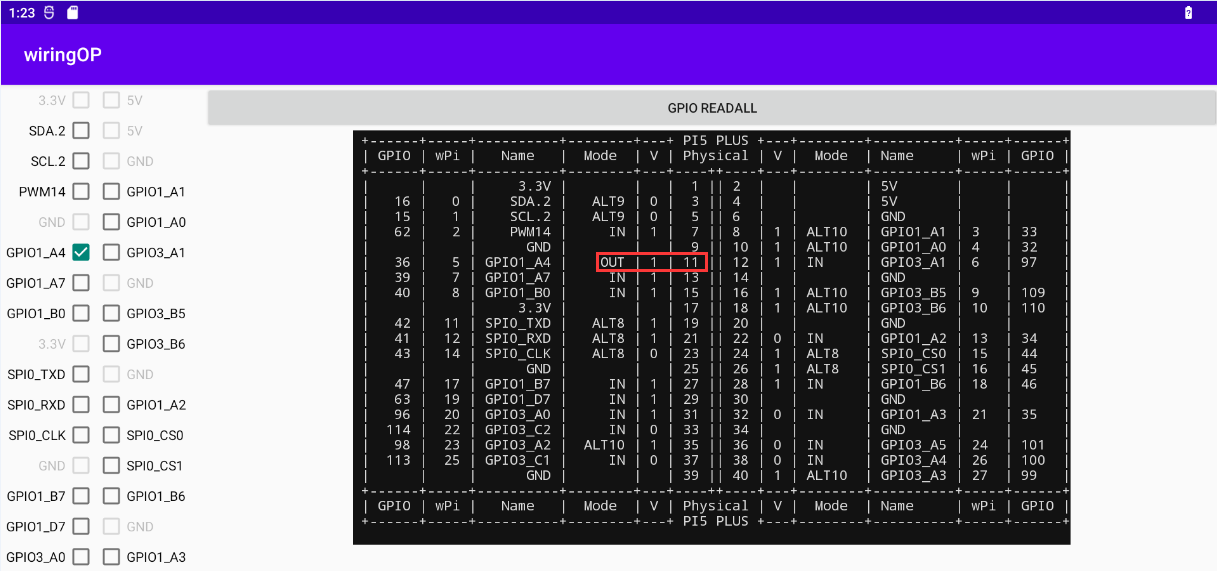
Click the CheckBox button in the figure below again to cancel the check status. Pin 11 will be set to low level. After setting, you can use a multimeter to measure the voltage value of the pin. If it is 0v, it means that the low level is set successfully.
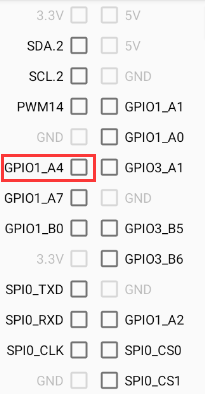
Then click the GPIO READALL button, you can see that the current mode of pin 11 is OUT, and the pin level is low
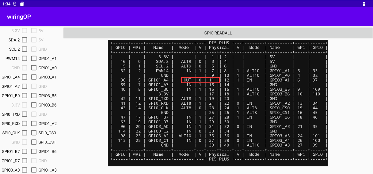


40pin UART test
UART3 and UART8 are enabled by default in Android. The position of the 40pin is shown in the figure below, and the corresponding device nodes are /dev/ttyS3 and /dev/ttyS8 respectively
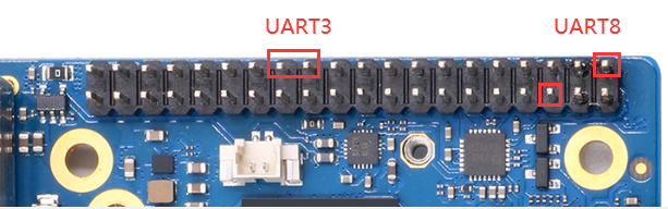
First click on the wiringOP icon to open the wiringOP APP
The main interface of wiringOP APP is displayed as shown in the figure below, and then click the UART_TEST button to open the UART test interface
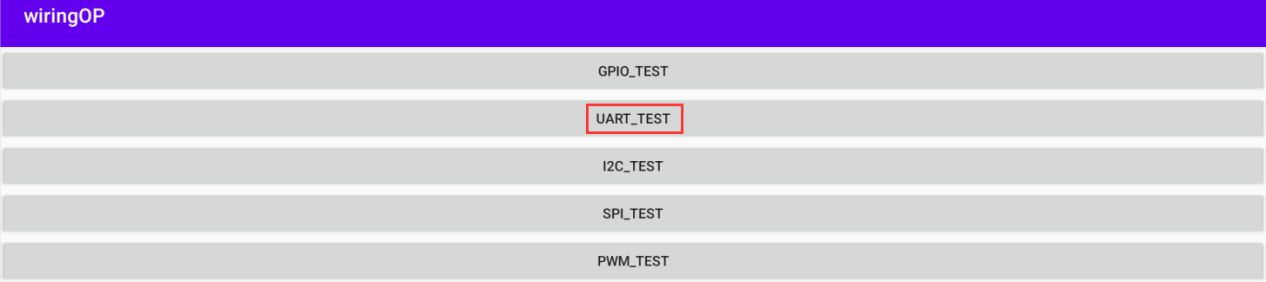
The serial port test interface of the APP is shown in the figure below


- Take the test of UART3 as an example below, select the /dev/ttyS3 node in the selection box, enter the baud rate you want to set in the edit box, and then click the OPEN button to open the /dev/ttyS3 node. After opening successfully, click the OPEN button becomes unselectable, and the CLOSE button and SEND button become selectable

Then use Dupont wire to short the RXD and TXD pins of uart3
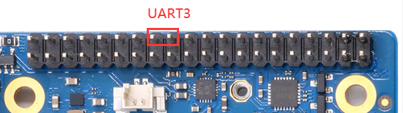
Then you can enter a character in the send edit box below, and click the SEND button to start sending


- If everything is normal, the received string will be displayed in the receiving box

40pin SPI test
From the table below, the available SPIs for Orange Pi 5 Plus are SPI0 and SPI4
The Android system opens the SPI0 configuration by default. Here is a demonstration to test the SPI0 interface through the w25q64 module. First, connect the w25q64 device to the SPI0 interface.
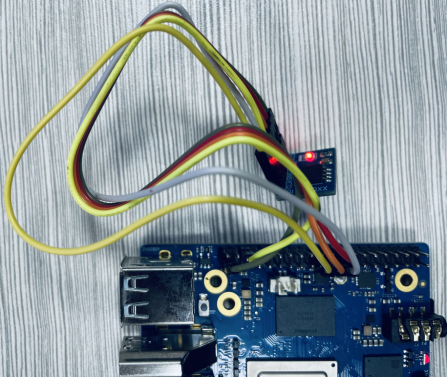
Then click the wiringOP icon to open the wiringOP APP
The main interface of wiringOP APP is displayed as shown in the figure below, click the SPI_TEST button to open the SPI test interface
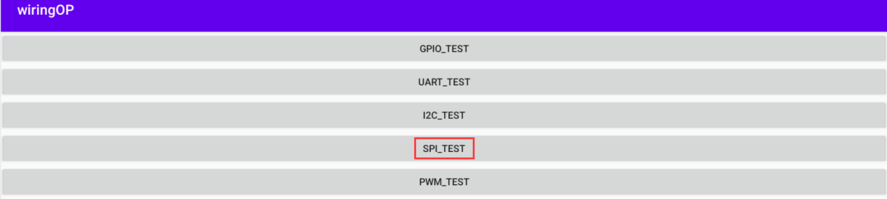
Then click the OPEN button to initialize the SPI


Then fill in the bytes that need to be sent, such as reading the ID information of w25q64, fill in the address 0x9f in data[0], and then click the TRANSFER button
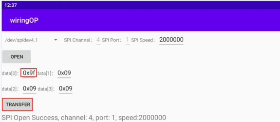
Finally, the APP will display the read ID information


The MANUFACTURER ID of the w25q64 module is EFh, and the Device ID is 4017h, corresponding to the value read above (h stands for hexadecimal)
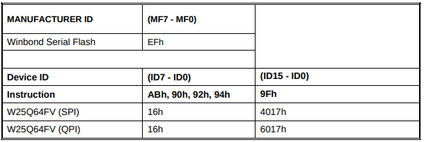

40pin PWM test
Android enables PWM10 and PWM14 by default, and the corresponding pins are located at 40pin as shown in the figure below:
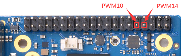
First click on the wiringOP icon to open the wiringOP APP
Then click the PWM_TEST button on the main interface of wiringOP to enter the PWM test interface
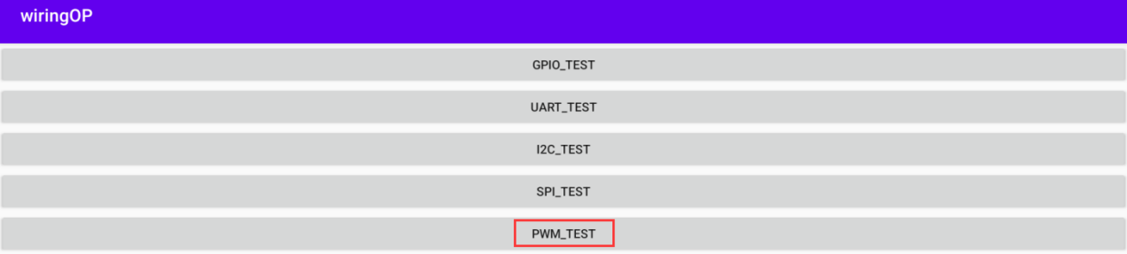
The base address corresponding to PWM10 is febe0020, and the base address corresponding to PWM14 is febf0020. Here, fd8b0020.pwm is displayed on the right of pwmchip0. At this time, you need to click the drop-down option to select other pwmchips until febe0020 or febf0020 is displayed on the right.
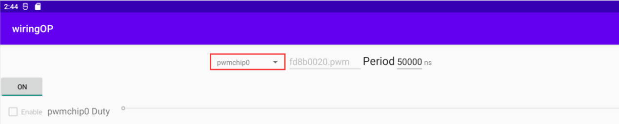
When the drop-down option menu selects pwmchip2, the corresponding base address of PWM10 is febe0020 on the right
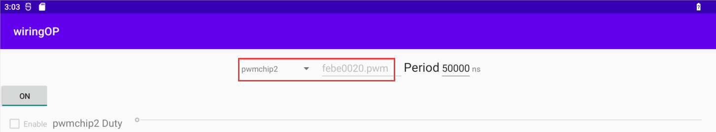
When the drop-down option menu selects pwmchip4, the corresponding base address of PWM14 is febe0020 on the right
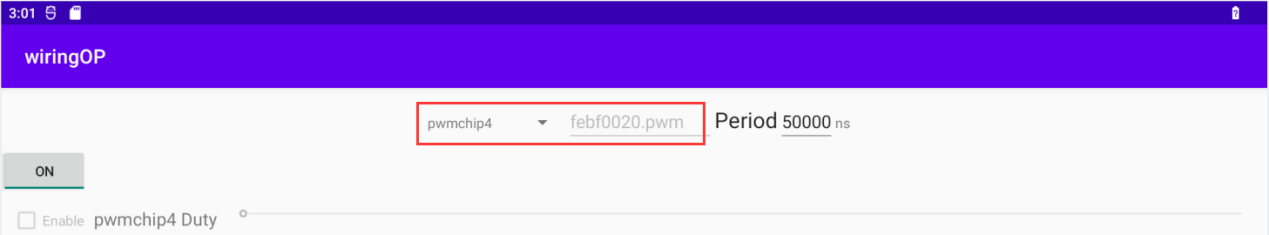
Take the test of PWM10 as an example, we need to select pwmchip2
Then confirm the PWM period, the default configuration is 50000ns, converted to PWM frequency is 20KHz, you can modify it yourself, click the open button to export PWM10
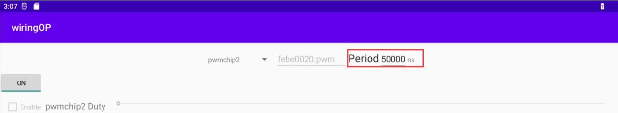
Then drag the drag bar below to change the PWM duty cycle, and then check Enable to output the PWM waveform


- Then use an oscilloscope to measure the 31st pin in the 40pin of the development board, and you can see the following waveform

How to use ADB
Use the data cable to connect to adb debugging
First prepare a good quality Type-C data cable
Then connect the development board and Ubuntu PC through the Type-C data cable. The position of the Type-C interface of the development board is shown in the figure below:
Then install the adb tool on the Ubuntu PC
test@test:~$ sudo apt update
test@test:~$ sudo apt -y install adb
You can view the identified ADB devices through the following command
test@test:~$ adb devices
List of devices attached
S63QCF54CJ device
test@test:~$ lsusb
Bus 003 Device 006: ID 2207:0006
Then you can log in to the android system through the adb shell on the Ubuntu PC
|
test@test:~$ adb shell console:/ $ |
- Execute the following command to remount the Android system
|
test@test:~$ adb root test@test:~$ adb remount |
- Then you can transfer files to the Android system
|
test@test:~$ adb push example.txt /system/ |
Use network connection adb debugging
|
Using the network adb does not require a data cable of the Typc-C interface to connect the computer and the development board, but to communicate through the network, so first of all, please ensure that the wired or wireless network of the development board has been connected, and then obtain the IP address of the development board, and then to use. |
Make sure that the service.adb.tcp.port of the Android system is set to port number 5555
console:/ # getprop | grep "adb.tcp"
[service.adb.tcp.port]: [5555]
If service.adb.tcp.port is not set, you can use the following command to set the port number of network adb
|
console:/ # setprop service.adb.tcp.port 5555 console:/ # stop adbd console:/ # start adbd |
Install adb tool on Ubuntu PC
test@test:~$ sudo apt update
test@test:~$ sudo apt install -y adb
Then connect network adb on Ubuntu PC
test@test:~$ adb connect 192.168.1.xxx (The IP address needs to be changed to the IP address of the development board)
* daemon not running; starting now at tcp:5037
* daemon started successfully
connected to 192.168.1.xxx:5555
test@test:~$ adb devices
List of devices attached
192.168.1.xxx:5555 device
Then you can log in to the android system through the adb shell on the Ubuntu PC
|
test@test:~$ adb shell console:/ # |
2.4G USB remote control tested by Android Box
A 2.4G USB remote control that has been tested so far is shown in the figure below
Contains a remote control

A USB wireless receiver
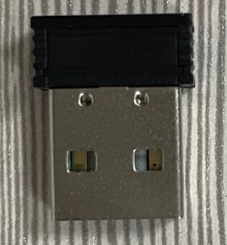
The Android Box system does not require any configuration, it can be used after plugging it in


How to use the infrared remote control of the Android Box system
The development board comes with an infrared receiver, and its location is shown in the figure below:
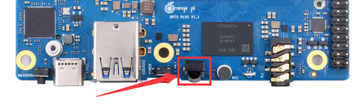
Before testing infrared reception, we need to prepare an infrared remote control

Note: The Android system provided by Orange Pi only supports the remote control provided by Orange Pi by default, and the remote control of TV or air conditioner cannot be used.
The Android Box system has been adapted to this remote control, and it can be used directly without other settings.


How to use HDMI CEC function in Android Box system
|
HDMI CEC allows users to control all connected devices through HDMI with only one remote control. Based on this function, we can control the development board with the remote control of the TV. Before testing this function, please make sure your TV supports HDMI CEC. |
First connect the development board to the TV through the HDMI cable, then power on and start
Then turn on the HDMI CEC function in the TV settings. Different TVs may have different ways to turn it on. Here we take Xiaomi TV as an example. Press the menu button on the remote control, then select CEC remote control and press the confirmation button
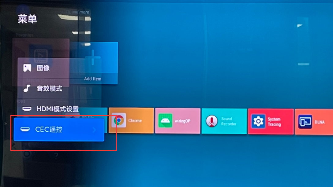
Then select "On" to open the HDMI CEC remote control
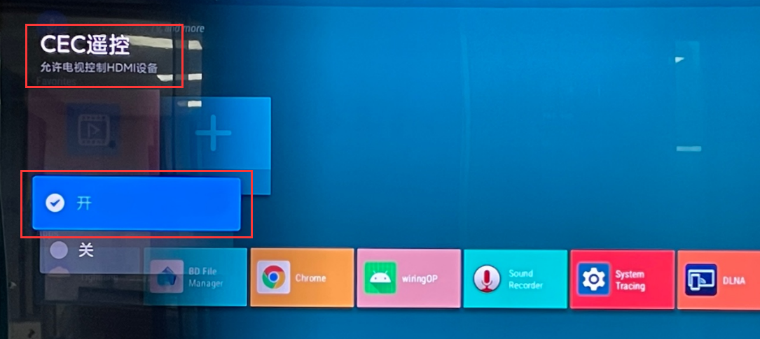
At this point, you can control the Android Box system of the development board through the remote control of the TV


How to compile Android 12 source code
Download Android 12 source code
First download the Android 12 source code sub-volume compressed package from Google network disk
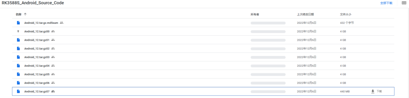
After downloading the sub-volume compression package of the Android 12 source code, please check whether the MD5 checksum is correct, if not, please download the source code again
test@test:~$ md5sum -c Android_12.tar.gz.md5sum
Android_12.tar.gz00: confirm
Android_12.tar.gz01: confirm
Android_12.tar.gz02: confirm
Android_12.tar.gz03: confirm
Android_12.tar.gz04: confirm
Android_12.tar.gz05: confirm
Android_12.tar.gz06: confirm
Android_12.tar.gz07: confirm
Then you need to merge multiple compressed files into one, and then decompress

|
test@test:~$ cat Android_12.tar.gz0* > Android_12.tar.gz test@test:~$ tar -xvf Android_12.tar.gz |
Compile the source code of Android 12
First install the software packages required to compile the Android12 source code
test@test:~$ sudo apt-get update
test@test:~$ sudo apt-get install -y git gnupg flex bison gperf build-essential \
zip curl zlib1g-dev gcc-multilib g++-multilib libc6-dev-i386 \
lib32ncurses5-dev x11proto-core-dev libx11-dev lib32z1-dev ccache \
libgl1-mesa-dev libxml2-utils xsltproc unzip
test@test:~$ sudo apt-get install -y u-boot-tools
There is a build.sh compilation script in the source code, and the compilation parameters are as follows
-U: compile uboot
-K: compile kernel
-A: compile android
-u: package and generate update.img and update_spi_nvme.img
-o: Compile the OTA package
-d: specify kernel dts
Compile uboot, kernel, android and package them into update.img
The command to compile and support HDMI 8K display image (LCD > off by default) is as follows:
test@test:~$ cd Android_12
test@test:~/ Android_12$ source build/envsetup.sh
test@test:~/ Android_12$ lunch rk3588_s-userdebug
test@test:~/ Android_12$ ./build.sh -AUKu
The command to compile and support LCD display image is as > follows:
test@test:~$ cd Android_12
test@test:~/ Android_12$ export DUAL_LCD=true
test@test:~/ Android_12$ source build/envsetup.sh
test@test:~/ Android_12$ lunch rk3588_s-userdebug
test@test:~/ Android_12$ ./build.sh -AUKu
The command to compile the image of the Box version is as > follows:
test@test:~$ cd Android_12
test@test:~/ Android_12$ export BOARD=orangepi5plus
test@test:~/ Android_12$ source build/envsetup.sh
test@test:~/ Android_12$ lunch rk3588_box-userdebug
test@test:~/ Android_12$ ./build.sh -AUKu
After the compilation is complete, the following information will be printed
********rkImageMaker ver 2.1********
Generating new image, please wait...
Writing head info...
Writing boot file...
Writing firmware...
Generating MD5 data...
MD5 data generated successfully!
New image generated successfully!
Making update.img OK.
Make update image ok!
The final image file will be placed in the rockdev/Image-rk3588_s directory. Among them, update.img is the boot image that supports TF card and eMMC, and update_spi_nvme.img is the boot image of NVME SSD
test@test:~/Android_12$ cd rockdev/Image-rk3588s_s
test@test:~/Android_12/rockdev/Image-rk3588s_s $ ls update*
update.img update_spi_nvme.img
If you compile the image of the Box version, the final generated image file will be placed in the rockdev/Image-rk3588_box directory
test@test:~/Android_12$ cd rockdev/Image-rk3588_box
test@test:~/Android_12/rockdev/Image-rk3588_box$ ls update*
update.img update_spi_nvme.img
Instructions for using the Orange Pi OS Droid system
Function adaptation of OPi OS Droid system
| Function | OPi OS Droid function adaptation |
| HDMI TX1 display | OK |
| HDMI TX1 Audio | OK |
| HDMI TX2 display | OK |
| HDMI TX2 Audio | OK |
| HDMI RX display | OK |
| HDMI RX Audio | OK |
| USB2.0X2 | OK |
| 2.5G PCIe network port X2 | OK |
| 2.5G PCIe network port light | OK |
| Debug serial port | OK |
| RTC | OK |
| FAN interface | OK |
| eMMC extension interface | OK |
| AP6275P-WIFI | OK |
| AP6275P-BT | OK |
| AX200-WIFI | NO |
| AX200-BT | NO |
| AX210-WIFI | NO |
| AX210-BT | NO |
| RTL8852BE-WIFI | OK |
| RTL8852BE-BT | OK |
| Recovery button | OK |
| Type-C interface USB3.0 function | OK |
| Type-C interface ADB function | OK |
| Type-C interface DP display function | OK |
| Type-C interface DP audio playback | OK |
| USB3.0 Hub | OK |
| switch button | OK |
| infrared function | OK |
| led light | OK |
| Onboard MIC | OK |
| headphone playback | OK |
| headphone recording | OK |
| SPK Horn | OK |
| 40PIN GPIO | OK |
| 40PIN I2C | OK |
| 40PIN SPI | OK |
| 40PIN UART | OK |
| 40PIN PWM | OK |
| TF card start | OK |
| SPI Flash+NVME solid state boot | OK |
| OV13850 camera | OK |
| OV13855 camera | OK |
| GPU | OK |
| VPU | OK |
| NPU | OK |
| MIPI LCD | NO |
| HDMI CEC | NO |
Test method of HDMI In
The location of the HDMI In interface on the development board is as follows:
Then use the HDMI to HDMI cable shown in the figure below to connect the HDMI output of other devices to the HDMI In interface of the development board
Make sure that the HDMI output of the device connected to the HDMI In interface is normal, and then open the HDMI In test APP
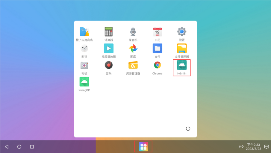
Then the window shown in the figure below will appear. At this time, the video input of HDMI In cannot be seen. You need to click the position marked in the red box in the figure below to enlarge it to full screen
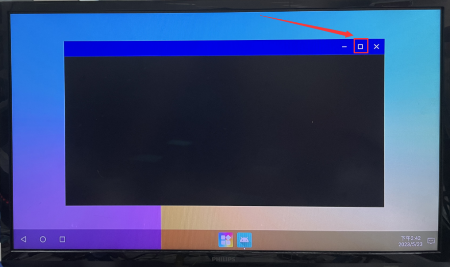
Then you can see the video input of HDMI In, and the audio input of HDMI In will also be output from the HDMI TX interface or headphone interface of the development board. The figure below shows the desktop of the Linux system of the OPi5 development board input through HDMI In.
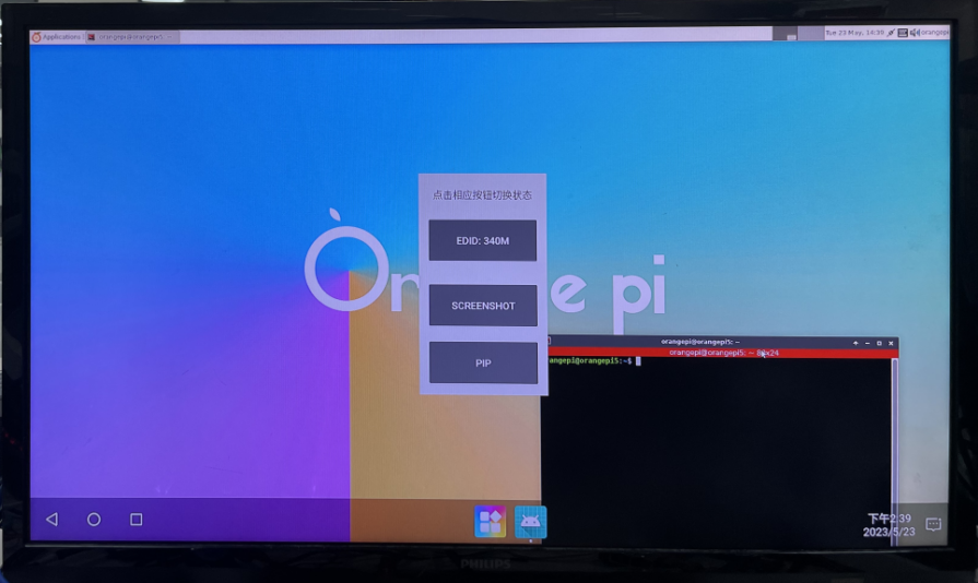


Appendix
User Manual Update History
| version | Date | Updated Notes |
| v1.0 | 2023-05-22 | initial version |
| v1.1 | 2023-05-24 |
1. How to use the infrared remote control of the Android Box system 2. Instructions for using the Orange Pi OS Droid system |
| v1.2 | 2023-05-26 |
1. Ubuntu/Debian: HDMI IN test method 2. Delete the instructions for using the RTL8821CU USB WIFI module, this module is not recommended |
| v1.3 | 2023-05-29 |
1. Update the method of using RKDevTool to burn the image to spiflash+ssd 2. Use RKDevTool to clear SPIFlash |
| v1.4 | 2023-05-31 |
1. Update the usage method of M.2 E-Key PCIe WIFI6+Bluetooth module 2. Ubuntu/Debian: How to use the ZFS file system 3. Ubuntu/Debian: Turn off the green light and blue light by default when booting 4. Add the instructions for using the Debian12 system (scattered in multiple sections) 5. Instructions for using the 5v pin in the 40pin interface of the development board to supply power |
| v1.5 | 2023-06-07 |
1. Add the picture of eMMC module 2. Correct the picture of the cooling fan interface 3. Add a method to check the temperature of nvme ssd |
Image update history
| Date | Updated Notes |
| 2023-05-19 |
Orangepi5plus_1.0.0_debian_bullseye_server_linux5.10.110.7z Orangepi5plus_1.0.0_debian_bullseye_desktop_xfce_linux5.10.110.7z Orangepi5plus_1.0.0_debian_bullseye_desktop_kde-plasma_linux5.10.110.7z Orangepi5plus_1.0.0_ubuntu_focal_server_linux5.10.110.7z Orangepi5plus_1.0.0_ubuntu_focal_desktop_xfce_linux5.10.110.7z Orangepi5plus_1.0.0_ubuntu_jammy_server_linux5.10.110.7z Orangepi5plus_1.0.0_ubuntu_jammy_desktop_xfce_linux5.10.110.7z Orangepi5plus_1.0.0_ubuntu_jammy_desktop_gnome_linux5.10.110.7z Opios-droid-aarch64-opi5plus-23.05-linux5.10.110.tar.gz Opios-droid-aarch64-opi5plus-23.05-linux5.10.110-spi-nvme.tar.gz OrangePi5Plus_RK3588_Android12_v1.0.0.tar.gz OrangePi5Plus_RK3588_Android12_lcd_v1.0.0.tar.gz OrangePi5Plus-RK3588_Android12-box_v1.0.0.tar.gz OrangePi5Plus_RK3588_Android12_spi-nvme_v1.0.0.tar.gz OrangePi5Plus_RK3588_Android12_spi-nvme_lcd_v1.0.0.tar.gz OrangePi5Plus-RK3588_Android12-box_spi-nvme_v1.0.0.tar.gz openwrt-aarch64-opi5plus-23.05-linux5.10.110-ext4.img.gz
|
| 2023-05-22 |
Opios-arch-aarch64-gnome-opi5plus-23.05-linux5.10.110.img.xz openwrt-rockchip -armv8-xunlong_orangepi-5-plus-spi-squashfs-sysupgrade.bin
|
| 2023-05-24 |
Orangepi5plus_1.0.2_debian_bullseye_desktop_kde-plasma_linux5.10.110
|
| 2023-05-26 |
Opios-arch-aarch64-gnome-opi5plus-23.05.1-linux5.10.110.img.xz
OrangePi5Plus_RK3588_Android12_v1.0.1.tar.gz OrangePi5Plus_RK3588_Android12_v1.0.1_lcd.tar.gz OrangePi5Plus_RK3588_Android12_v1.0.1_spi-nvme.tar.gz OrangePi5Plus_RK3588_Android12_v1.0.1_lcd_spi-nvme.tar.gz
Orangepi5plus_1.0.4_debian_bullseye_desktop_kde-plasma_linux5.10.110.7z
Orangepi5plus_1.0.4_debian_bullseye_desktop_xfce_linux5.10.110.7z
Orangepi5plus_1.0.4_ubuntu_focal_desktop_xfce_linux5.10.110.7z
Orangepi5plus_1.0.4_debian_bullseye_server_linux5.10.110.7z
|
| 2023-05-29 |
Opios-droid-aarch64-opi5plus-23.05.1-linux5.10.110-en.tar.gz Opios-droid-aarch64-opi5plus-23.05.1-linux5.10.110-en-spi-nvme.tar.gz
|
| 2023-06-01 |
Orangepi5plus_1.0.6_ubuntu_jammy_desktop_xfce_linux5.10.110.7z
Orangepi5plus_1.0.6_debian_bullseye_desktop_xfce_linux5.10.110.7z Orangepi5plus_1.0.6_debian_bullseye_desktop_kde-plasma_linux5.10.110.7z
Orangepi5plus_1.0.6_ubuntu_focal_desktop_xfce_linux5.10.110.7z Orangepi5plus_1.0.6_ubuntu_jammy_desktop_gnome_linux5.10.110.7z Orangepi5plus_1.0.6_ubuntu_focal_server_linux5.10.110.7z Orangepi5plus_1.0.6_debian_bullseye_server_linux5.10.110.7z Orangepi5plus_1.0.6_ubuntu_jammy_server_linux5.10.110.7z
Orangepi5plus_1.0.6_debian_bookworm_server_linux5.10.110 Orangepi5plus_1.0.6_debian_bookworm_desktop_xfce_linux5.10.110
|