Difference between revisions of "Orange Pi Zero 2W"
(→40pin SPI test method) |
(→Download orangepi-build from github) |
||
| (11 intermediate revisions by the same user not shown) | |||
| Line 111: | Line 111: | ||
<div class="figure"> | <div class="figure"> | ||
| − | [[File:zero2w-img3.png]] | + | [[File:zero2w-img3.png|800px]] |
</div> | </div> | ||
| Line 118: | Line 118: | ||
<div class="figure"> | <div class="figure"> | ||
| − | [[File:zero2w-img4.png]] | + | [[File:zero2w-img4.png|800px]] |
</div> | </div> | ||
| Line 127: | Line 127: | ||
<div class="figure"> | <div class="figure"> | ||
| − | [[File:zero2w-img5.png]] | + | [[File:zero2w-img5.png|800px]] |
</div> | </div> | ||
<span id="orange-pi-zero-2w-24pin-expansion-board-interface-details"></span> | <span id="orange-pi-zero-2w-24pin-expansion-board-interface-details"></span> | ||
| + | |||
== Orange Pi Zero 2w 24pin expansion board interface details == | == Orange Pi Zero 2w 24pin expansion board interface details == | ||
<div class="figure"> | <div class="figure"> | ||
| − | [[File:zero2w-img6.png]] | + | [[File:zero2w-img6.png|800px]] |
</div> | </div> | ||
| − | [[File:zero2w-img7.png]] | + | [[File:zero2w-img7.png|800px]] |
{| class="wikitable" style="background-color:#ffffdc;width:800px;" | {| class="wikitable" style="background-color:#ffffdc;width:800px;" | ||
| Line 8,706: | Line 8,707: | ||
<div class="figure"> | <div class="figure"> | ||
| − | [[File:zero2w-img272.png|center]] | + | [[File:zero2w-img272.png|center|800px]] |
</div> | </div> | ||
| Line 10,783: | Line 10,784: | ||
<div style="display: flex;"> | <div style="display: flex;"> | ||
| − | {| class="wikitable" style="width:390px;margin-right: 20px;text-align: center;" | + | ::{| class="wikitable" style="width:390px;margin-right: 20px;text-align: center;" |
|- | |- | ||
| '''GPIO NO.''' | | '''GPIO NO.''' | ||
| Line 11,037: | Line 11,038: | ||
# As can be seen from the table below, the Android12 TV system has i2c1 and i2c2 turned on by default. | # As can be seen from the table below, the Android12 TV system has i2c1 and i2c2 turned on by default. | ||
| − | {| class="wikitable" | + | <div style="display: flex;"> |
| + | ::{| class="wikitable" style="width:390px;margin-right: 20px;text-align: center;" | ||
|- | |- | ||
| − | | '''GPIO | + | | '''GPIO NO.''' |
| '''GPIO''' | | '''GPIO''' | ||
| '''Function''' | | '''Function''' | ||
| − | | ''' | + | | '''Pin''' |
| − | |||
| − | |||
| − | |||
| − | |||
| − | |||
|- | |- | ||
| style="text-align: left;"| | | style="text-align: left;"| | ||
| Line 11,053: | Line 11,050: | ||
| '''3.3V''' | | '''3.3V''' | ||
| '''1''' | | '''1''' | ||
| − | |||
| − | |||
| − | |||
| − | |||
| − | |||
|- | |- | ||
| − | | '''264''' | + | | '''<span style="color:#FF0000">264</span>''' |
| − | | '''PI8''' | + | | '''<span style="color:#FF0000">PI8</span>''' |
| − | | '''TWI1-SDA''' | + | | '''<span style="color:#FF0000">TWI1-SDA</span>''' |
| − | | ''' | + | | '''<span style="color:#FF0000">3</span>''' |
| − | |||
| − | |||
| − | |||
| − | |||
| − | |||
|- | |- | ||
| − | | '''263''' | + | | '''<span style="color:#FF0000">263</span>''' |
| − | | '''PI7''' | + | | '''<span style="color:#FF0000">PI7</span>''' |
| − | | '''TWI1-SCL''' | + | | '''<span style="color:#FF0000">TWI1-SCL</span>''' |
| − | | ''' | + | | '''<span style="color:#FF0000">5</span>''' |
| − | |||
| − | |||
| − | |||
| − | |||
| − | |||
|- | |- | ||
| '''269''' | | '''269''' | ||
| Line 11,083: | Line 11,065: | ||
| '''PWM3''' | | '''PWM3''' | ||
| '''7''' | | '''7''' | ||
| − | |||
| − | |||
| − | |||
| − | |||
| − | |||
|- | |- | ||
| style="text-align: left;"| | | style="text-align: left;"| | ||
| Line 11,093: | Line 11,070: | ||
| '''GND''' | | '''GND''' | ||
| '''9''' | | '''9''' | ||
| − | |||
| − | |||
| − | |||
| − | |||
| − | |||
|- | |- | ||
| '''226''' | | '''226''' | ||
| Line 11,103: | Line 11,075: | ||
| '''UART5_TX''' | | '''UART5_TX''' | ||
| '''11''' | | '''11''' | ||
| − | |||
| − | |||
| − | |||
| − | |||
| − | |||
|- | |- | ||
| '''227''' | | '''227''' | ||
| Line 11,113: | Line 11,080: | ||
| '''UART5_RX''' | | '''UART5_RX''' | ||
| '''13''' | | '''13''' | ||
| − | |||
| − | |||
| − | |||
| − | |||
| − | |||
|- | |- | ||
| '''261''' | | '''261''' | ||
| Line 11,123: | Line 11,085: | ||
| '''UART2_TX''' | | '''UART2_TX''' | ||
| '''15''' | | '''15''' | ||
| − | |||
| − | |||
| − | |||
| − | |||
| − | |||
|- | |- | ||
| style="text-align: left;"| | | style="text-align: left;"| | ||
| Line 11,133: | Line 11,090: | ||
| '''3.3V''' | | '''3.3V''' | ||
| '''17''' | | '''17''' | ||
| − | |||
| − | |||
| − | |||
| − | |||
| − | |||
|- | |- | ||
| '''231''' | | '''231''' | ||
| Line 11,143: | Line 11,095: | ||
| '''SPI1_MOSI''' | | '''SPI1_MOSI''' | ||
| '''19''' | | '''19''' | ||
| − | |||
| − | |||
| − | |||
| − | |||
| − | |||
|- | |- | ||
| '''232''' | | '''232''' | ||
| Line 11,153: | Line 11,100: | ||
| '''SPI1_MISO''' | | '''SPI1_MISO''' | ||
| '''21''' | | '''21''' | ||
| − | |||
| − | |||
| − | |||
| − | |||
| − | |||
|- | |- | ||
| '''230''' | | '''230''' | ||
| Line 11,163: | Line 11,105: | ||
| '''SPI1_CLK''' | | '''SPI1_CLK''' | ||
| '''23''' | | '''23''' | ||
| − | |||
| − | |||
| − | |||
| − | |||
| − | |||
|- | |- | ||
| style="text-align: left;"| | | style="text-align: left;"| | ||
| Line 11,173: | Line 11,110: | ||
| '''GND''' | | '''GND''' | ||
| '''25''' | | '''25''' | ||
| − | |||
| − | |||
| − | |||
| − | |||
| − | |||
|- | |- | ||
| − | | '''266''' | + | | '''<span style="color:#FF0000">266</span>''' |
| − | | '''PI10''' | + | | '''<span style="color:#FF0000">PI10</span>''' |
| − | | '''TWI2-SDA''' | + | | '''<span style="color:#FF0000">TWI2-SDA</span>''' |
| − | | '''27 | + | | '''<span style="color:#FF0000">27</span>''' |
| − | |||
| − | |||
| − | |||
| − | |||
| − | |||
|- | |- | ||
| '''256''' | | '''256''' | ||
| Line 11,193: | Line 11,120: | ||
| style="text-align: left;"| | | style="text-align: left;"| | ||
| '''29''' | | '''29''' | ||
| − | |||
| − | |||
| − | |||
| − | |||
| − | |||
|- | |- | ||
| '''271''' | | '''271''' | ||
| Line 11,203: | Line 11,125: | ||
| style="text-align: left;"| | | style="text-align: left;"| | ||
| '''31''' | | '''31''' | ||
| − | |||
| − | |||
| − | |||
| − | |||
| − | |||
|- | |- | ||
| '''268''' | | '''268''' | ||
| Line 11,213: | Line 11,130: | ||
| '''PWM2''' | | '''PWM2''' | ||
| '''33''' | | '''33''' | ||
| − | |||
| − | |||
| − | |||
| − | |||
| − | |||
|- | |- | ||
| '''258''' | | '''258''' | ||
| Line 11,223: | Line 11,135: | ||
| style="text-align: left;"| | | style="text-align: left;"| | ||
| '''35''' | | '''35''' | ||
| − | |||
| − | |||
| − | |||
| − | |||
| − | |||
|- | |- | ||
| '''272''' | | '''272''' | ||
| Line 11,233: | Line 11,140: | ||
| style="text-align: left;"| | | style="text-align: left;"| | ||
| '''37''' | | '''37''' | ||
| − | |||
| − | |||
| − | |||
| − | |||
| − | |||
|- | |- | ||
| style="text-align: left;"| | | style="text-align: left;"| | ||
| Line 11,243: | Line 11,145: | ||
| '''GND''' | | '''GND''' | ||
| '''39''' | | '''39''' | ||
| − | |||
| − | |||
| − | |||
| − | |||
| − | |||
|} | |} | ||
| − | + | {| class="wikitable" style="width:390px;margin-right: 20px;text-align: center;" | |
| − | |||
| − | |||
| − | |||
| − | |||
| − | |||
| − | |||
| − | |||
| − | |||
| − | |||
| − | |||
| − | |||
| − | |||
| − | |||
| − | |||
| − | |||
| − | |||
| − | |||
| − | |||
| − | |||
| − | |||
| − | |||
| − | |||
| − | |||
| − | |||
| − | |||
| − | |||
| − | |||
| − | |||
| − | |||
| − | |||
| − | |||
| − | |||
| − | |||
| − | |||
| − | |||
| − | |||
| − | |||
| − | |||
| − | |||
| − | |||
| − | |||
| − | |||
| − | |||
| − | |||
| − | |||
| − | |||
| − | |||
| − | |||
| − | |||
| − | |||
| − | |||
| − | |||
| − | |||
| − | |||
| − | |||
| − | |||
| − | |||
| − | |||
| − | |||
| − | |||
|- | |- | ||
| − | | ''' | + | | '''Pin''' |
| − | |||
| − | |||
| − | |||
| − | |||
| − | |||
| '''Function''' | | '''Function''' | ||
| '''GPIO''' | | '''GPIO''' | ||
| − | | '''GPIO | + | | '''GPIO NO.''' |
|- | |- | ||
| − | |||
| − | |||
| − | |||
| − | |||
| − | |||
| '''2''' | | '''2''' | ||
| '''5V''' | | '''5V''' | ||
| Line 11,331: | Line 11,158: | ||
| style="text-align: left;"| | | style="text-align: left;"| | ||
|- | |- | ||
| − | + | | '''4''' | |
| − | |||
| − | |||
| − | |||
| − | |||
| − | | '''4''' | ||
| '''5V''' | | '''5V''' | ||
| style="text-align: left;"| | | style="text-align: left;"| | ||
| style="text-align: left;"| | | style="text-align: left;"| | ||
|- | |- | ||
| − | |||
| − | |||
| − | |||
| − | |||
| − | |||
| '''6''' | | '''6''' | ||
| '''GND''' | | '''GND''' | ||
| Line 11,351: | Line 11,168: | ||
| style="text-align: left;"| | | style="text-align: left;"| | ||
|- | |- | ||
| − | |||
| − | |||
| − | |||
| − | |||
| − | |||
| '''8''' | | '''8''' | ||
| '''UART0_TX''' | | '''UART0_TX''' | ||
| Line 11,361: | Line 11,173: | ||
| '''224''' | | '''224''' | ||
|- | |- | ||
| − | |||
| − | |||
| − | |||
| − | |||
| − | |||
| '''10''' | | '''10''' | ||
| '''UART0_RX''' | | '''UART0_RX''' | ||
| Line 11,371: | Line 11,178: | ||
| '''225''' | | '''225''' | ||
|- | |- | ||
| − | |||
| − | |||
| − | |||
| − | |||
| − | |||
| '''12''' | | '''12''' | ||
| style="text-align: left;"| | | style="text-align: left;"| | ||
| Line 11,381: | Line 11,183: | ||
| '''257''' | | '''257''' | ||
|- | |- | ||
| − | |||
| − | |||
| − | |||
| − | |||
| − | |||
| '''14''' | | '''14''' | ||
| '''GND''' | | '''GND''' | ||
| Line 11,391: | Line 11,188: | ||
| style="text-align: left;"| | | style="text-align: left;"| | ||
|- | |- | ||
| − | |||
| − | |||
| − | |||
| − | |||
| − | |||
| '''16''' | | '''16''' | ||
| '''PWM4''' | | '''PWM4''' | ||
| Line 11,401: | Line 11,193: | ||
| '''270''' | | '''270''' | ||
|- | |- | ||
| − | |||
| − | |||
| − | |||
| − | |||
| − | |||
| '''18''' | | '''18''' | ||
| style="text-align: left;"| | | style="text-align: left;"| | ||
| Line 11,411: | Line 11,198: | ||
| '''228''' | | '''228''' | ||
|- | |- | ||
| − | |||
| − | |||
| − | |||
| − | |||
| − | |||
| '''20''' | | '''20''' | ||
| '''GND''' | | '''GND''' | ||
| Line 11,421: | Line 11,203: | ||
| style="text-align: left;"| | | style="text-align: left;"| | ||
|- | |- | ||
| − | |||
| − | |||
| − | |||
| − | |||
| − | |||
| '''22''' | | '''22''' | ||
| '''UART2_RX''' | | '''UART2_RX''' | ||
| Line 11,431: | Line 11,208: | ||
| '''262''' | | '''262''' | ||
|- | |- | ||
| − | |||
| − | |||
| − | |||
| − | |||
| − | |||
| '''24''' | | '''24''' | ||
| '''SPI1_CS0''' | | '''SPI1_CS0''' | ||
| Line 11,441: | Line 11,213: | ||
| '''229''' | | '''229''' | ||
|- | |- | ||
| − | |||
| − | |||
| − | |||
| − | |||
| − | |||
| '''26''' | | '''26''' | ||
| '''SPI1_CS1''' | | '''SPI1_CS1''' | ||
| Line 11,451: | Line 11,218: | ||
| '''233''' | | '''233''' | ||
|- | |- | ||
| − | | ''' | + | | '''<span style="color:#FF0000">28</span>''' |
| − | + | | '''<span style="color:#FF0000">TWI2-SCL</span>''' | |
| − | + | | '''<span style="color:#FF0000">PI9</span>''' | |
| − | + | | '''<span style="color:#FF0000">265</span>''' | |
| − | |||
| − | |||
| − | | '''TWI2-SCL''' | ||
| − | | '''PI9''' | ||
| − | | '''265''' | ||
|- | |- | ||
| − | |||
| − | |||
| − | |||
| − | |||
| − | |||
| '''30''' | | '''30''' | ||
| '''GND''' | | '''GND''' | ||
| Line 11,471: | Line 11,228: | ||
| style="text-align: left;"| | | style="text-align: left;"| | ||
|- | |- | ||
| − | |||
| − | |||
| − | |||
| − | |||
| − | |||
| '''32''' | | '''32''' | ||
| '''PWM1''' | | '''PWM1''' | ||
| Line 11,481: | Line 11,233: | ||
| '''267''' | | '''267''' | ||
|- | |- | ||
| − | |||
| − | |||
| − | |||
| − | |||
| − | |||
| '''34''' | | '''34''' | ||
| '''GND''' | | '''GND''' | ||
| Line 11,491: | Line 11,238: | ||
| style="text-align: left;"| | | style="text-align: left;"| | ||
|- | |- | ||
| − | |||
| − | |||
| − | |||
| − | |||
| − | |||
| '''36''' | | '''36''' | ||
| style="text-align: left;"| | | style="text-align: left;"| | ||
| Line 11,501: | Line 11,243: | ||
| '''76''' | | '''76''' | ||
|- | |- | ||
| − | |||
| − | |||
| − | |||
| − | |||
| − | |||
| '''38''' | | '''38''' | ||
| style="text-align: left;"| | | style="text-align: left;"| | ||
| Line 11,511: | Line 11,248: | ||
| '''260''' | | '''260''' | ||
|- | |- | ||
| − | |||
| − | |||
| − | |||
| − | |||
| − | |||
| '''40''' | | '''40''' | ||
| style="text-align: left;"| | | style="text-align: left;"| | ||
| Line 11,521: | Line 11,253: | ||
| '''259''' | | '''259''' | ||
|} | |} | ||
| + | </div> | ||
<ol start="2" style="list-style-type: decimal;"> | <ol start="2" style="list-style-type: decimal;"> | ||
| − | <li> | + | <li>The device node corresponding to i2c1 is '''/dev/i2c-1''', and the device node corresponding to i2c2 is '''/dev/i2c-2'''</li> |
| − | + | {| class="wikitable" style="width:800px;" | |
| − | + | |- | |
| + | | | ||
| + | apollo-p2:/ # '''ls /dev/i2c-*''' | ||
| + | '''<span style="color:#FF0000">/dev/i2c-1 /dev/i2c-2</span>''' /dev/i2c-5 | ||
| + | |} | ||
| + | </ol> | ||
<ol start="3" style="list-style-type: decimal;"> | <ol start="3" style="list-style-type: decimal;"> | ||
| − | <li> | + | <li>First open wiringOP APP on the desktop</li> |
| − | |||
| − | |||
| + | [[File:zero2w-img351.png]] | ||
| + | </ol> | ||
<ol start="4" style="list-style-type: decimal;"> | <ol start="4" style="list-style-type: decimal;"> | ||
| − | <li> | + | <li>Then click the '''I2C_TEST''' button to open the i2c test interface</li> |
| − | + | [[File:zero2w-img370.png]] | |
| − | + | </ol> | |
| − | [[File:zero2w- | ||
| − | |||
| − | </ | ||
<ol start="5" style="list-style-type: decimal;"> | <ol start="5" style="list-style-type: decimal;"> | ||
| − | <li> | + | <li>The i2c test interface of wiringOP is shown in the figure below</li> |
| − | |||
| − | |||
| + | [[File:zero2w-img371.png]] | ||
| + | </ol> | ||
<ol start="6" style="list-style-type: decimal;"> | <ol start="6" style="list-style-type: decimal;"> | ||
| − | <li>Then you | + | <li>Then click the device node selection box in the upper left corner to select the i2c you want to test</li> |
| − | |||
| − | |||
| + | [[File:zero2w-img372.png]] | ||
| + | </ol> | ||
<ol start="7" style="list-style-type: decimal;"> | <ol start="7" style="list-style-type: decimal;"> | ||
| − | <li>Then | + | <li>Then connect an i2c device to the 40pin i2c pin. Here we take the ds1307 rtc module as an example.</li> |
| − | |||
| − | |||
| + | [[File:zero2w-img178.png]] | ||
| + | </ol> | ||
<ol start="8" style="list-style-type: decimal;"> | <ol start="8" style="list-style-type: decimal;"> | ||
| − | <li> | + | <li><p>The i2c address of the ds1307 rtc module is 0x68. After connecting the lines, we can use the '''i2cdetect -y 1''' or '''i2cdetect -y 2''' command on the serial port command line to check whether the i2c address of the ds1307 rtc module can be scanned. If you can see the address 0x68, it means that the ds1307 rtc module is wired correctly.</p> |
| − | + | {| class="wikitable" style="width:800px;" | |
| − | [[File:zero2w- | + | |- |
| − | + | | | |
| − | < | + | <p>apollo-p2:/ # '''i2cdetect -y 1'''</p> |
| − | <li>Then | + | <p>'''Or'''</p> |
| − | + | <p>apollo-p2:/ # '''i2cdetect -y 2'''</p> | |
| − | [[File:zero2w- | + | |} |
| − | + | <p>[[File:zero2w-img373.png]]</p></li> | |
| − | < | + | <li><p>Then set the i2c address to 0x68 in wiringOP, and then click the '''OPEN''' button to open i2c</p> |
| − | + | <p>[[File:zero2w-img374.png]]</p></li> | |
| − | + | <li><p>After clicking the '''OPEN''' button to open i2c, the display is as follows</p> | |
| − | + | <p>[[File:zero2w-img375.png]]</p></li> | |
| − | < | + | <li><p>Then we test writing a value to the register of the rtc module, for example, writing 0x55 to the 0x1c address</p> |
| − | |||
| − | |||
| − | < | ||
| − | <li><p> | ||
<ol style="list-style-type: lower-alpha;"> | <ol style="list-style-type: lower-alpha;"> | ||
| − | <li> | + | <li><p>We first set the address of the register to be written to 0x1c</p> |
| − | </li></ol> | + | <p>[[File:zero2w-img376.png]]</p></li> |
| + | <li><p>Then set the value to be written to 0x55</p> | ||
| + | <p>[[File:zero2w-img377.png]]</p></li> | ||
| + | <li><p>Then click the '''WRITE BYTE''' button to perform the writing action</p> | ||
| + | <p>[[File:zero2w-img378.png]]</p></li></ol> | ||
| + | </li> | ||
| + | <li><p>Then click the '''READ BYTE''' button to read the value of the 0x1c register. If it displays 0x55, it means that the i2c read and write test has passed.</p> | ||
| + | <p>[[File:zero2w-img379.png]]</p></li></ol> | ||
| − | + | <span id="pin-pwm-test"></span> | |
| − | + | === 40pin PWM test === | |
| − | |||
| − | + | # As can be seen from the table below, the available pwm are pwm1, pwm2, pwm3 and pwm4. | |
| − | + | <div style="display: flex;"> | |
| − | + | ::{| class="wikitable" style="width:390px;margin-right: 20px;text-align: center;" | |
| − | + | |- | |
| − | + | | '''GPIO NO.''' | |
| − | + | | '''GPIO''' | |
| − | + | | '''Function''' | |
| − | < | + | | '''Pin''' |
| − | < | + | |- |
| − | + | | style="text-align: left;"| | |
| − | + | | style="text-align: left;"| | |
| − | + | | '''3.3V''' | |
| − | + | | '''1''' | |
| − | + | |- | |
| − | + | | '''264''' | |
| − | + | | '''PI8''' | |
| − | + | | '''TWI1-SDA''' | |
| − | + | | '''3''' | |
| − | + | |- | |
| − | + | | '''263''' | |
| − | + | | '''PI7''' | |
| − | ''' | + | | '''TWI1-SCL''' |
| − | + | | '''5''' | |
| − | + | |- | |
| − | < | + | | '''<span style="color:#FF0000">269</span>''' |
| − | + | | '''<span style="color:#FF0000">PI13</span>''' | |
| − | + | | '''<span style="color:#FF0000">PWM3</span>''' | |
| − | + | | '''<span style="color:#FF0000">7</span>''' | |
| − | <span | + | |- |
| − | = | + | | style="text-align: left;"| |
| − | + | | style="text-align: left;"| | |
| − | ''' | + | | '''GND''' |
| − | + | | '''9''' | |
| − | + | |- | |
| − | + | | '''226''' | |
| − | ''' | + | | '''PH2''' |
| − | + | | '''UART5_TX''' | |
| − | + | | '''11''' | |
| − | + | |- | |
| − | + | | '''227''' | |
| − | + | | '''PH3''' | |
| − | + | | '''UART5_RX''' | |
| − | + | | '''13''' | |
| − | ''' | + | |- |
| − | + | | '''261''' | |
| − | ''' | + | | '''PI5''' |
| − | + | | '''UART2_TX''' | |
| − | ''' | + | | '''15''' |
| − | + | |- | |
| − | ''' | + | | style="text-align: left;"| |
| − | + | | style="text-align: left;"| | |
| − | + | | '''3.3V''' | |
| − | < | + | | '''17''' |
| − | < | + | |- |
| − | < | + | | '''231''' |
| − | < | + | | '''PH7''' |
| − | + | | '''SPI1_MOSI''' | |
| − | + | | '''19''' | |
| − | + | |- | |
| − | + | | '''232''' | |
| − | + | | '''PH8''' | |
| − | + | | '''SPI1_MISO''' | |
| − | + | | '''21''' | |
| − | + | |- | |
| − | + | | '''230''' | |
| − | + | | '''PH6''' | |
| − | + | | '''SPI1_CLK''' | |
| − | + | | '''23''' | |
| − | + | |- | |
| − | + | | style="text-align: left;"| | |
| − | + | | style="text-align: left;"| | |
| − | + | | '''GND''' | |
| − | + | | '''25''' | |
| − | + | |- | |
| − | + | | '''266''' | |
| − | + | | '''PI10''' | |
| − | + | | '''TWI2-SDA''' | |
| − | + | | '''27''' | |
| − | + | |- | |
| − | + | | '''256''' | |
| − | + | | '''PI0''' | |
| − | + | | style="text-align: left;"| | |
| − | + | | '''29''' | |
| − | + | |- | |
| − | + | | '''271''' | |
| − | + | | '''PI15''' | |
| − | + | | style="text-align: left;"| | |
| − | + | | '''31''' | |
| − | + | |- | |
| − | + | | '''<span style="color:#FF0000">268</span>''' | |
| − | + | | '''<span style="color:#FF0000">PI12</span>''' | |
| − | + | | '''<span style="color:#FF0000">PWM2</span>''' | |
| − | + | | '''<span style="color:#FF0000">33</span>''' | |
| − | + | |- | |
| − | + | | '''258''' | |
| − | + | | '''PI2''' | |
| − | + | | style="text-align: left;"| | |
| − | + | | '''35''' | |
| − | + | |- | |
| − | + | | '''272''' | |
| − | + | | '''PI16''' | |
| − | + | | style="text-align: left;"| | |
| − | + | | '''37''' | |
| − | + | |- | |
| − | + | | style="text-align: left;"| | |
| − | + | | style="text-align: left;"| | |
| − | + | | '''GND''' | |
| − | + | | '''39''' | |
| − | + | |} | |
| − | + | {| class="wikitable" style="width:390px;margin-right: 20px;text-align: center;" | |
| − | + | |- | |
| − | + | | '''Pin''' | |
| − | + | | '''Function''' | |
| − | + | | '''GPIO''' | |
| − | + | | '''GPIO NO.''' | |
| − | + | |- | |
| − | + | | '''2''' | |
| − | + | | '''5V''' | |
| − | + | | style="text-align: left;"| | |
| − | + | | style="text-align: left;"| | |
| − | + | |- | |
| − | ''' | + | | '''4''' |
| − | + | | '''5V''' | |
| − | + | | style="text-align: left;"| | |
| − | + | | style="text-align: left;"| | |
| − | + | |- | |
| − | + | | '''6''' | |
| − | + | | '''GND''' | |
| − | + | | style="text-align: left;"| | |
| − | + | | style="text-align: left;"| | |
| − | + | |- | |
| − | + | | '''8''' | |
| − | + | | '''UART0_TX''' | |
| − | + | | '''PH0''' | |
| − | + | | '''224''' | |
| − | + | |- | |
| − | + | | '''10''' | |
| − | + | | '''UART0_RX''' | |
| − | + | | '''PH1''' | |
| − | <ol start=" | + | | '''225''' |
| − | <li>Then | + | |- |
| − | + | | '''12''' | |
| − | test | + | | style="text-align: left;"| |
| − | + | | '''PI1''' | |
| − | <ol start=" | + | | '''257''' |
| − | <li> | + | |- |
| − | + | | '''14''' | |
| − | + | | '''GND''' | |
| − | + | | style="text-align: left;"| | |
| − | + | | style="text-align: left;"| | |
| − | + | |- | |
| − | ''' | + | | '''<span style="color:#FF0000">16</span>''' |
| − | + | | '''<span style="color:#FF0000">PWM4</span>''' | |
| − | + | | '''<span style="color:#FF0000">PI14</span>''' | |
| + | | '''<span style="color:#FF0000">270</span>''' | ||
| + | |- | ||
| + | | '''18''' | ||
| + | | style="text-align: left;"| | ||
| + | | '''PH4''' | ||
| + | | '''228''' | ||
| + | |- | ||
| + | | '''20''' | ||
| + | | '''GND''' | ||
| + | | style="text-align: left;"| | ||
| + | | style="text-align: left;"| | ||
| + | |- | ||
| + | | '''22''' | ||
| + | | '''UART2_RX''' | ||
| + | | '''PI6''' | ||
| + | | '''262''' | ||
| + | |- | ||
| + | | '''24''' | ||
| + | | '''SPI1_CS0''' | ||
| + | | '''PH5''' | ||
| + | | '''229''' | ||
| + | |- | ||
| + | | '''26''' | ||
| + | | '''SPI1_CS1''' | ||
| + | | '''PH9''' | ||
| + | | '''233''' | ||
| + | |- | ||
| + | | '''28''' | ||
| + | | '''TWI2-SCL''' | ||
| + | | '''PI9''' | ||
| + | | '''265''' | ||
| + | |- | ||
| + | | '''30''' | ||
| + | | '''GND''' | ||
| + | | style="text-align: left;"| | ||
| + | | style="text-align: left;"| | ||
| + | |- | ||
| + | | '''<span style="color:#FF0000">32</span>''' | ||
| + | | '''<span style="color:#FF0000">PWM1</span>''' | ||
| + | | '''<span style="color:#FF0000">PI11</span>''' | ||
| + | | '''<span style="color:#FF0000">267</span>''' | ||
| + | |- | ||
| + | | '''34''' | ||
| + | | '''GND''' | ||
| + | | style="text-align: left;"| | ||
| + | | style="text-align: left;"| | ||
| + | |- | ||
| + | | '''36''' | ||
| + | | style="text-align: left;"| | ||
| + | | '''PC12''' | ||
| + | | '''76''' | ||
| + | |- | ||
| + | | '''38''' | ||
| + | | style="text-align: left;"| | ||
| + | | '''PI4''' | ||
| + | | '''260''' | ||
| + | |- | ||
| + | | '''40''' | ||
| + | | style="text-align: left;"| | ||
| + | | '''PI3''' | ||
| + | | '''259''' | ||
| + | |} | ||
| + | </div> | ||
| + | |||
| + | <ol start="2" style="list-style-type: decimal;"> | ||
| + | <li>First click the wiringOP icon to open wiringOP APP</li> | ||
| + | |||
| + | [[File:zero2w-img351.png]] | ||
| + | </ol> | ||
| + | <ol start="3" style="list-style-type: decimal;"> | ||
| + | <li>Then click the '''PWM_TEST''' button on the main interface of wiringOP to enter the PWM test interface</li> | ||
| + | |||
| + | [[File:zero2w-img380.png]] | ||
| + | </ol> | ||
| + | <ol start="4" style="list-style-type: decimal;"> | ||
| + | <li>The PWM test interface is as follows</li> | ||
| + | |||
| + | <div class="figure"> | ||
| + | |||
| + | [[File:zero2w-img381.png]] | ||
| + | |||
| + | </div></ol> | ||
| + | <ol start="5" style="list-style-type: decimal;"> | ||
| + | <li>Then set which PWM you want to use in the Channel. The default is PWM1. If you want to set it to PWM2, just enter 2 in the Channel. PWM3 and PWM4 and so on.</li> | ||
| + | |||
| + | [[File:zero2w-img382.png]] | ||
| + | </ol> | ||
| + | <ol start="6" style="list-style-type: decimal;"> | ||
| + | <li>Then you can set the PWM period. The default configuration is '''50000ns'''. The converted PWM frequency is '''20KHz'''</li> | ||
| + | |||
| + | [[File:zero2w-img383.png]] | ||
| + | </ol> | ||
| + | <ol start="7" style="list-style-type: decimal;"> | ||
| + | <li>Then click the '''EXPORT'''button to export PWM</li> | ||
| − | + | [[File:zero2w-img384.png]] | |
| + | </ol> | ||
| + | <ol start="8" style="list-style-type: decimal;"> | ||
| + | <li>Then drag the progress bar below to change the PWM duty cycle, and then check '''Enable''' to output the PWM waveform.</li> | ||
| − | + | [[File:zero2w-img385.png]] | |
| + | </ol> | ||
| + | <ol start="9" style="list-style-type: decimal;"> | ||
| + | <li>Then use an oscilloscope to measure the corresponding pins in the 40pin development board and you can see the following waveform.</li> | ||
| − | INFO: ---------------------------------------- | + | [[File:zero2w-img386.png]] |
| + | </ol> | ||
| + | <span id="how-to-compile-android-12-source-code"></span> | ||
| + | |||
| + | = '''How to compile Android 12 source code''' = | ||
| + | |||
| + | <span id="download-the-source-code-of-android-12"></span> | ||
| + | == Download the source code of Android 12 == | ||
| + | |||
| + | <ol style="list-style-type: decimal;"> | ||
| + | <li><p>First download the compressed package of the Android 12 source code and the compressed package of the files modified by Orange Pi Zero2w from Google Cloud Drive</p> | ||
| + | <ol style="list-style-type: lower-alpha;"> | ||
| + | <li>Google Cloud Drive</li> | ||
| + | |||
| + | [[File:zero2w-img387.png]] | ||
| + | </ol> | ||
| + | </li></ol> | ||
| + | <ol start="2" style="list-style-type: decimal;"> | ||
| + | <li>After downloading the compressed package of Android 12 source code, please check whether the MD5 checksum is correct. If it is incorrect, please download the source code again. Here's how to check the MD5 checksum:</li> | ||
| + | {| class="wikitable" style="width:800px;" | ||
| + | |- | ||
| + | | | ||
| + | test@test:~$ '''md5sum -c H618-Android12-Src.tar.gz.md5sum''' | ||
| + | |||
| + | H618-Android12-Src.tar.gzaa: '''<span style="color:#FF0000">OK</span>''' | ||
| + | |||
| + | H618-Android12-Src.tar.gzab: '''<span style="color:#FF0000">OK</span>''' | ||
| + | |||
| + | ...... | ||
| + | |} | ||
| + | </ol> | ||
| + | <ol start="3" style="list-style-type: decimal;"> | ||
| + | <li>Then you need to merge multiple compressed files into one, and then extract the Android source code. The command looks like this:</li> | ||
| + | {| class="wikitable" style="width:800px;" | ||
| + | |- | ||
| + | | | ||
| + | test@test:~$ '''cat H618-Android12-Src.tar.gz<span style="color:#FF0000">a</span>* > H618-Android12-Src.tar.gz''' | ||
| + | |||
| + | test@test:~$ '''tar -xvf H618-Android12-Src.tar.gz''' | ||
| + | |} | ||
| + | </ol> | ||
| + | <ol start="4" style="list-style-type: decimal;"> | ||
| + | <li>Then unzip the compressed package of the files modified by Orange Pi Zero2w</li> | ||
| + | {| class="wikitable" style="width:800px;" | ||
| + | |- | ||
| + | | | ||
| + | test@test:~$ '''tar zxf opizero2w_android12_patches.tar.gz''' | ||
| + | |||
| + | test@test:~$ '''ls''' | ||
| + | |||
| + | '''opizero2w_android12_patches''' opizero2w_android12_patches.tar.gz | ||
| + | |} | ||
| + | </ol> | ||
| + | <ol start="5" style="list-style-type: decimal;"> | ||
| + | <li>Then copy the files modified by Orange Pi Zero2w to the Android source code</li> | ||
| + | {| class="wikitable" style="width:800px;" | ||
| + | |- | ||
| + | | | ||
| + | test@test:~$ '''cp -rf opizero2w_android12_patches/* H618-Android12-Src/''' | ||
| + | |} | ||
| + | </ol> | ||
| + | <span id="compile-the-source-code-of-android-12"></span> | ||
| + | |||
| + | == Compile the source code of Android 12 == | ||
| + | |||
| + | {| class="wikitable" style="background-color:#ffffdc;width:800px;" | ||
| + | |- | ||
| + | | | ||
| + | <big>'''Android12 is compiled on an x86_64 computer with <span style="color:#FF0000">Ubuntu 22.04</span> installed. Other versions of Ubuntu system package dependencies may have some differences. The image download address of the Ubuntu 22.04 <span style="color:#FF0000">amd64</span> version is as follows:''' | ||
| + | |||
| + | [https://repo.huaweicloud.com/ubuntu-releases/22.04/ubuntu-22.04.2-desktop-amd64.iso '''https://repo.huaweicloud.com/ubuntu-releases/22.04/ubuntu-22.04.2-desktop-amd64.iso'''] | ||
| + | |||
| + | '''The x86_64 computer hardware configuration for compiling Android12 source code recommends a memory of 16GB or more, and a hard disk space of 200GB or more is recommended. The more CPU cores, the better.'''</big> | ||
| + | |} | ||
| + | |||
| + | # First install the software packages needed to compile Android12 source code | ||
| + | |||
| + | ::{| class="wikitable" style="width:800px;" | ||
| + | |- | ||
| + | | | ||
| + | test@test:~$ '''sudo apt-get update''' | ||
| + | |||
| + | test@test:~$ '''sudo apt-get install -y git gnupg flex bison gperf build-essential \''' | ||
| + | |||
| + | '''zip curl zlib1g-dev gcc-multilib g++-multilib libc6-dev-i386 \''' | ||
| + | |||
| + | '''lib32ncurses5-dev x11proto-core-dev libx11-dev lib32z1-dev ccache \''' | ||
| + | |||
| + | '''libgl1-mesa-dev libxml2-utils xsltproc unzip u-boot-tools python-is-python3 \''' | ||
| + | |||
| + | '''libssl-dev libncurses5 clang gawk''' | ||
| + | |} | ||
| + | |||
| + | <ol start="2" style="list-style-type: decimal;"> | ||
| + | <li><p>Then compile the code in the longan folder, which mainly contains u-boot and linux kernel</p> | ||
| + | <ol style="list-style-type: lower-alpha;"> | ||
| + | <li>First run '''./build.sh config''' to set compilation options</li> | ||
| + | {| class="wikitable" style="width:800px;" | ||
| + | |- | ||
| + | | | ||
| + | <p>test@test:~$ '''cd H618-Android12-Src/longan'''</p> | ||
| + | <p>test@test:~/H618-Android12-Src/longan$ '''./build.sh config'''</p> | ||
| + | |||
| + | |||
| + | <p>Welcome to mkscript setup progress</p> | ||
| + | <p>All available platform:</p> | ||
| + | :<p>0. android</p> | ||
| + | :<p>1. linux</p> | ||
| + | <p>Choice [android]: '''<span style="color:#FF0000">0</span>'''</p> | ||
| + | <p>All available ic:</p> | ||
| + | :<p>0. h618</p> | ||
| + | <p>Choice [h618]: '''<span style="color:#FF0000">0</span>'''</p> | ||
| + | <p>All available board:</p> | ||
| + | :<p>0. ft</p> | ||
| + | :<p>1. p1</p> | ||
| + | :<p>2. p2</p> | ||
| + | :<p>3. p7</p> | ||
| + | :<p>4. p7l</p> | ||
| + | :<p>5. perf1</p> | ||
| + | :<p>6. perf2</p> | ||
| + | :<p>7. perf3</p> | ||
| + | :<p>8. qa</p> | ||
| + | <p>Choice [p2]: '''<span style="color:#FF0000">2</span>'''</p> | ||
| + | <p>All available flash:</p> | ||
| + | :<p>0. default</p> | ||
| + | :<p>1. nor</p> | ||
| + | <p>Choice [default]: '''<span style="color:#FF0000">0</span>'''</p> | ||
| + | <p>All available kern_ver:</p> | ||
| + | :<p>0. linux-5.4</p> | ||
| + | <p>Choice [linux-5.4]: '''<span style="color:#FF0000">0</span>'''</p> | ||
| + | <p>All available arch:</p> | ||
| + | :<p>0. arm</p> | ||
| + | :<p>1. arm64</p> | ||
| + | <p>Choice [arm64]: '''<span style="color:#FF0000">1</span>'''</p> | ||
| + | <p>'''......'''</p> | ||
| + | <p>*** Default configuration is based on 'sun50iw9p1smp_h618_android_defconfig'</p> | ||
| + | <p>#</p> | ||
| + | <p># configuration written to .config</p> | ||
| + | <p>#</p> | ||
| + | <p>make[1]: Leaving directory '/home/test/H618-Android12-Src/longan/out/kernel/build'</p> | ||
| + | <p>make: Leaving directory '/home/test/H618-Android12-Src/longan/kernel/linux-5.4'</p> | ||
| + | <p>INFO: clean buildserver</p> | ||
| + | <p>INFO: prepare_buildserver</p> | ||
| + | |} | ||
| + | </ol> | ||
| + | <ol start="2" style="list-style-type: lower-alpha;"> | ||
| + | <li>Then run the '''./build.sh''' script to start compilation.</li> | ||
| + | {| class="wikitable" style="width:800px;" | ||
| + | |- | ||
| + | | | ||
| + | test@test:~/H618-Android12-Src/longan$ '''./build.sh''' | ||
| + | |} | ||
| + | </ol> | ||
| + | <ol start="3" style="list-style-type: lower-alpha;"> | ||
| + | <li>After compilation is completed, you will see the following output</li> | ||
| + | {| class="wikitable" style="width:800px;" | ||
| + | |- | ||
| + | | | ||
| + | sun50iw9p1 compile Kernel successful | ||
| + | |||
| + | INFO: Prepare toolchain ... | ||
| + | |||
| + | '''......''' | ||
| + | |||
| + | INFO: build kernel OK. | ||
| + | |||
| + | INFO: build rootfs ... | ||
| + | |||
| + | INFO: skip make rootfs for android | ||
| + | |||
| + | INFO: ---------------------------------------- | ||
INFO: build lichee OK. | INFO: build lichee OK. | ||
| − | INFO: ---------------------------------------- | + | INFO: ---------------------------------------- |
| − | + | |} | |
| − | <ol start="3" style="list-style-type: decimal;"> | + | </ol> |
| − | <li>Then use the following command to compile the Android source code and generate the final Android image</li> | + | </li></ol> |
| − | + | <ol start="3" style="list-style-type: decimal;"> | |
| − | test@test:~$ '''cd H618-Android12-Src''' | + | <li>Then use the following command to compile the Android source code and generate the final Android image</li> |
| − | + | {| class="wikitable" style="width:800px;" | |
| − | test@test:~/H618-Android12-Src$ '''source build/envsetup.sh''' | + | |- |
| − | + | | | |
| − | test@test:~/H618-Android12-Src$ '''lunch apollo_p2-userdebug''' | + | test@test:~$ '''cd H618-Android12-Src''' |
| − | + | ||
| − | test@test:~/H618-Android12-Src$ '''make -j8''' | + | test@test:~/H618-Android12-Src$ '''source build/envsetup.sh''' |
| − | + | ||
| − | test@test:~/H618-Android12-Src$ '''pack''' | + | test@test:~/H618-Android12-Src$ '''lunch apollo_p2-userdebug''' |
| − | + | ||
| − | <ol start="4" style="list-style-type: decimal;"> | + | test@test:~/H618-Android12-Src$ '''make -j8''' |
| − | <li><p>The storage path of the Android image generated by compilation is:</p> | + | |
| − | <p>'''longan/out/h618_android12_p2_uart0.img'''</p></li></ol> | + | test@test:~/H618-Android12-Src$ '''pack''' |
| − | + | |} | |
| − | <span id="appendix"></span> | + | </ol> |
| − | + | <ol start="4" style="list-style-type: decimal;"> | |
| − | = '''Appendix''' = | + | <li><p>The storage path of the Android image generated by compilation is:</p> |
| − | + | {| class="wikitable" style="width:800px;" | |
| − | <span id="user-manual-update-history"></span> | + | |- |
| − | == User manual update history == | + | | |
| − | + | <p>'''longan/out/h618_android12_p2_uart0.img'''</p> | |
| − | {| class="wikitable" style="width:800px;text-align: center;" | + | |} |
| − | |- | + | </li></ol> |
| − | | '''Version''' | + | |
| − | | '''Date''' | + | <span id="appendix"></span> |
| − | | '''Release Notes''' | + | |
| − | |- | + | = '''Appendix''' = |
| − | | v1.0 | + | |
| − | | 2023-09-14 | + | <span id="user-manual-update-history"></span> |
| − | | initial version | + | == User manual update history == |
| − | |} | + | |
| − | + | {| class="wikitable" style="width:800px;text-align: center;" | |
| − | <span id="image-update-history"></span> | + | |- |
| − | == Image update history == | + | | '''Version''' |
| − | + | | '''Date''' | |
| − | {| class="wikitable" style="width:800px;" | + | | '''Release Notes''' |
| − | |- | + | |- |
| − | | style="text-align: center;"| '''Date''' | + | | v1.0 |
| − | + | | 2023-09-14 | |
| − | | style="text-align: center;"| '''Release Notes''' | + | | initial version |
| − | |- | + | |} |
| − | | style="text-align: center;"| 2023-09-14 | + | |
| − | | | + | <span id="image-update-history"></span> |
| − | orangepizero2w_1.0.0_debian_bullseye_server_linux5.4.125.7z | + | == Image update history == |
| − | + | ||
| − | orangepizero2w_1.0.0_ubuntu_focal_server_linux5.4.125.7z | + | {| class="wikitable" style="width:800px;" |
| − | + | |- | |
| − | orangepizero2w_1.0.0_ubuntu_focal_desktop_xfce_linux5.4.125.7z | + | | style="text-align: center;"| '''Date''' |
| − | + | ||
| − | orangepizero2w_1.0.0_debian_bullseye_desktop_xfce_linux5.4.125.7z | + | | style="text-align: center;"| '''Release Notes''' |
| − | + | |- | |
| − | orangepizero2w_1.0.0_ubuntu_jammy_server_linux6.1.31.7z | + | | style="text-align: center;"| 2023-09-14 |
| − | + | | | |
| − | orangepizero2w_1.0.0_debian_bookworm_server_linux6.1.31.7z | + | orangepizero2w_1.0.0_debian_bullseye_server_linux5.4.125.7z |
| − | + | ||
| − | orangepizero2w_1.0.0_debian_bullseye_server_linux6.1.31.7z | + | orangepizero2w_1.0.0_ubuntu_focal_server_linux5.4.125.7z |
| − | + | ||
| − | orangepizero2w_1.0.0_ubuntu_jammy_desktop_xfce_linux6.1.31.7z | + | orangepizero2w_1.0.0_ubuntu_focal_desktop_xfce_linux5.4.125.7z |
| − | + | ||
| − | orangepizero2w_1.0.0_debian_bookworm_desktop_xfce_linux6.1.31.7z | + | orangepizero2w_1.0.0_debian_bullseye_desktop_xfce_linux5.4.125.7z |
| − | + | ||
| − | orangepizero2w_1.0.0_debian_bullseye_desktop_xfce_linux6.1.31.7z | + | |
| − | + | orangepizero2w_1.0.0_ubuntu_jammy_server_linux6.1.31.7z | |
| − | OrangePi_Zero2w_Android12_v1.0.tar.gz | + | |
| + | orangepizero2w_1.0.0_debian_bookworm_server_linux6.1.31.7z | ||
| + | |||
| + | orangepizero2w_1.0.0_debian_bullseye_server_linux6.1.31.7z | ||
| + | |||
| + | orangepizero2w_1.0.0_ubuntu_jammy_desktop_xfce_linux6.1.31.7z | ||
| + | |||
| + | orangepizero2w_1.0.0_debian_bookworm_desktop_xfce_linux6.1.31.7z | ||
| + | |||
| + | orangepizero2w_1.0.0_debian_bullseye_desktop_xfce_linux6.1.31.7z | ||
| + | |||
| + | |||
| + | OrangePi_Zero2w_Android12_v1.0.tar.gz | ||
| + | |||
Opios-arch-aarch64-xfce-opizero2w-23.09-linux6.1.31.img.xz | Opios-arch-aarch64-xfce-opizero2w-23.09-linux6.1.31.img.xz | ||
Latest revision as of 20:33, 27 September 2023
Contents
- 1 Basic features of Orange Pi Zero 2w
- 2 Introduction to the use of development boards
- 2.1 Prepare necessary accessories
- 2.2 Download the development board image and related information
- 2.3 Method of burning Linux image to TF card based on Windows PC
- 2.4 Method to burn Linux image to TF card based on Ubuntu PC
- 2.5 Method of burning Android image to TF card
- 2.6 Instructions for using micro-linux system in onboard SPI Flash
- 2.7 Start the Orange Pie development board
- 2.8 How to use the debugging serial port
- 2.9 Instructions for using the 5v pin in the 40pin interface of the development board for power supply
- 3 Debian/Ubuntu Server and Xfce desktop system usage instructions
- 3.1 Supported linux image types and kernel versions
- 3.2 Linux kernel driver adaptation situation
- 3.3 Linux command format description in this manual
- 3.4 Linux system login instructions
- 3.4.1 Linux system default login account and password
- 3.4.2 How to set up automatic login of Linux system terminal
- 3.4.3 Instructions for automatic login of Linux desktop version system
- 3.4.4 Setting method for automatic login of root user in Linux desktop system
- 3.4.5 How to disable the desktop in Linux desktop system
- 3.5 Onboard LED light test instructions
- 3.6 Operation instructions for rootfs partition capacity of Linux system in TF card
- 3.6.1 The first startup will automatically expand the capacity of the rootfs partition in the TF card.
- 3.6.2 Method to prohibit automatic expansion of rootfs partition capacity in TF card
- 3.6.3 Method to manually expand the capacity of rootfs partition in TF card
- 3.6.4 Method to reduce the capacity of rootfs partition in TF card
- 3.7 24Pin expansion board interface pin description
- 3.8 How to use the two LRADC buttons on the 24pin expansion board
- 3.9 Network connection test
- 3.10 SSH remote login development board
- 3.11 HDMI test
- 3.12 How to use Bluetooth
- 3.13 USB interface test
- 3.14 Audio test
- 3.15 Infrared reception test
- 3.16 Temperature sensor
- 3.17 40 Pin Interface pin description
- 3.18 How to install wiringOP
- 3.19 40pin interface GPIO, I2C, UART, SPI and PWM testing
- 3.20 How to install and use wiringOP-Python
- 3.21 Hardware watchdog test
- 3.22 Check the chipid of H618 chip
- 3.23 Python related instructions
- 3.24 How to install Docker
- 3.25 How to install Home Assistant
- 3.26 OpenCV installation method
- 3.27 Set up the Chinese environment and install the Chinese input method
- 3.28 How to remotely log in to the Linux system desktop
- 3.29 QT installation method
- 3.30 ROS installation method
- 3.31 How to install kernel header files
- 3.32 Testing of some programming languages supported by Linux system
- 3.33 Method of uploading files to the development board Linux system
- 3.34 Instructions for using the logo on and off the machine
- 3.35 How to turn on the power button in Linux5.4
- 3.36 How to shut down and restart the development board
- 4 Linux SDK——orangepi-build usage instructions
- 5 Instructions for using the Orange Pi OS Arch system
- 6 Android 12 TV system usage instructions
- 6.1 Supported Android versions
- 6.2 Android 12 TV function adaptation status
- 6.3 Onboard LED light display instructions
- 6.4 How to return to the previous interface in Android
- 6.5 How to use ADB
- 6.6 View how to set HDMI display resolution
- 6.7 WI-FI connection method
- 6.8 How to use WI-FI hotspot
- 6.9 How to check the IP address of the Ethernet port
- 6.10 Bluetooth connection method
- 6.11 How to set USB0 to HOST mode
- 6.12 How to use USB camera
- 6.13 Android system ROOT description
- 6.14 How to use MiracastReceiver to cast the mobile phone screen to the development board
- 6.15 Method of turning on and off the machine through buttons or infrared remote control
- 6.16 40pin interface GPIO, UART, SPI test
- 7 How to compile Android 12 source code
- 8 Appendix
Basic features of Orange Pi Zero 2w
What is Orange Pi Zero 2w
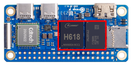
Orange Pi is an open source single-board card computer, a new generation of arm64 development board, which can run operating systems such as Android TV 12, Ubuntu and Debian. The Orange Pi Zero 2w development board uses the Allwinner H618 system-on-chip, and can optionally have 1GB or 1.5GB or 2GB or 4GB LPDDR4 memory.
Usage of Orange Pi Zero 2w
We can use it to achieve:
- A small Linux desktop computer
- A small Linux network server
- Install the Klipper host computer to control the 3D printer
- Android TV TV box
|
Of course, there are more functions. Relying on a powerful ecosystem and a variety of expansion accessories, Orange Pi can help users easily achieve delivery from ideas to prototypes to mass production. It is an ideal choice for makers, dreamers, and hobbyists. An ideal creative platform for readers. |
Who is Orange Pi Zero 2w designed for?
The Orange Pi development board is not only a consumer product, but also designed for anyone who wants to use technology to create and innovate. It's a simple, fun, and practical tool you can use to shape the world around you.
Hardware features of Orange Pi Zero 2w
|
Introduction to hardware features
| |
| CPU |
Allwinner H618 quad-core 64-bit 1.5GHz high-performance Cortex-A53 processor |
| GPU |
Mali G31 MP2 Supports OpenGL ES 1.0/2.0/3.2、OpenCL 2.0 |
| Memory |
1GB/1.5GB/2GB/4GB LPDDR4 (shared with GPU) |
| Onboard storage |
TF card slot, 16MB SPI Flash |
| WIFI+BT |
• 20U5622 chip, supports IEEE 802.11 a/b/g/n/ac, BT5.0 |
| Video Output |
• Mini HDMI 2.0 interface |
| Audio Output |
• Mini HDMI output |
| Power Supply |
Type-C 5V/2A |
| USB 2.0 port |
Type-C USB2.0 x 2 |
| 40pinexpansion interface |
Used to expand GPIO, UART, I2C, SPI, PWM |
| 24pinexpansion interface |
Used to expand USB2.0 x 2, 100M Ethernet, infrared reception, audio output, TV-OUT output, power on/off button, LRADC button x 2 |
| LED Light |
Power light and status light |
| Supported OS |
Android 12 TV, Debi an11, Debian12, Ubuntu22.04, Ubuntu20.04, Orange Pi OS(Arch)etc. |
|
Appearance specifications introduction
| |
| PCB Size |
30mm x 65mm x 1.2mm |
| Weight |
12.5g |
Top view and bottom view of Orange Pi Zero 2w
Top view:

Bottom view:

Orange Pi Zero 2w interface details

Orange Pi Zero 2w 24pin expansion board interface details


|
The diameters of the four positioning holes are all 3.0mm. |
Introduction to the use of development boards
Prepare necessary accessories
TF card, high-speed SanDisk card with minimum capacity of 8GB, class 10 or above

When using other brands of TF cards (non-SanDisk TF cards), as shown in the picture below (including but not limited to these cards), some friends have reported that problems will occur during system startup, such as the system getting stuck halfway through startup. Or the reboot command cannot be used normally, and it was finally solved after replacing the SanDisk TF card. Therefore, if you are using a non-SanDisk TF card and find problems with system startup or use, please replace it with a SanDisk TF card and then test again.


There are currently reports that some TF cards have problems booting on Orange Pi Zero 2w.
In addition, TF cards that can be used normally on other types of development boards are not guaranteed to be able to start normally on Orange Pi Zero 2w. Please pay special attention to this point.
TF card reader, used to read and write TF cards

Mini HDMI to HDMI cable, used to connect the development board to an HDMI monitor or TV for display


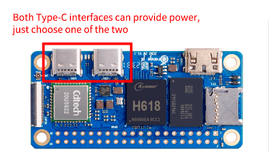
Power supply. If you have a 5V/2A or 5V/3A power supply, you only need to prepare a USB to Type C interface data cable as shown in the picture on the left below. You can also use a cable similar to the picture on the right below. 5V/2A or 5V/3A high-quality USB Type C interface power adapter integrated with the power head.


Both Type-C interfaces on the development board can be used for power supply.
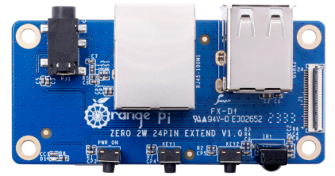
24pin expansion board
USB interface mouse and keyboard, as long as it is a standard USB interface mouse and keyboard, the mouse and keyboard can be used to control the Orange Pi development board
Infrared remote control, mainly used to control Android TV system

Note that the remote control of the air conditioner or the TV cannot control the Orange Pi development board. By default, only the remote control provided by Orange Pi can.
Network cable to connect the development board to the Internet
AV video cable. If you want to display video through the TV-OUT interface instead of the HDMI interface, you need to connect the development board to the TV through the AV video cable.

Heat sink. If you are worried that the temperature of the development board is too high, you can add some heat sinks and stick the heat sinks on the H618 chip and memory chip.

5V cooling fan, as shown in the figure below. There are 5V and GND pins on the 40pin interface of the development board that can be connected to the cooling fan. The spacing of the 40pin pins is 2.54mm. The power interface of the cooling fan can be purchased according to this specification.
Note that the 5V pin can be used directly after the development board is plugged in and no other settings are required. In addition, the voltage output by the 5V pin cannot be adjusted or turned off through software.
The pin headers on the 40pin interface are not soldered by default, and you need to solder them yourself before you can use them.
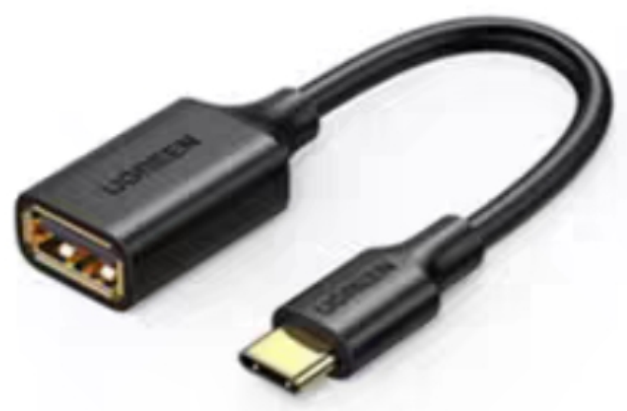
Type-C to USB cable for connecting USB devices
USB to TTL module and Dupont cable. When using the serial port debugging function, a USB to TTL module and Dupont cable are needed to connect the development board and the computer.
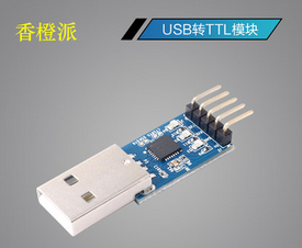
Note that the TTL level used by the development board is 3.3v. In addition to the USB to TTL module shown in the picture above, other similar 3.3v USB to TTL modules are generally available.
X64 computer with Ubuntu and Windows operating systems installed


| 1 | Ubuntu22.04 PC | Optional, used to compile Android and Linux source code |
| 2 | Windows PC | For burning Android and Linux images |
- The download URL for the Chinese version of the information is
The download URL for the English version of the information is
The information mainly includes
a. Android source code: saved on Google Cloud Drive
b. Linux source code: saved on Github
c. Android image: saved on Google Cloud Drive
d. Ubuntu image: saved on Google Cloud Drive
e. Debian image: saved on Google Cloud Drive
f. Orange Pi OS (Arch) image: saved on Google Cloud Drive
g. User manual and schematic diagram: chip-related data manuals will also be placed here
h. Official tools: mainly include software needed when using the development board
Method of burning Linux image to TF card based on Windows PC
|
Note that the Linux image mentioned here specifically refers to the Linux distribution image such as Debian or Ubuntu downloaded from the Orange Pi information download page. |
How to burn Linux image using balenaEtcher
- First prepare a TF card with 8GB or larger capacity. The transmission speed of the TF card must be class10 or above. It is recommended to use TF cards from SanDisk and other brands.
- Then use the card reader to insert the TF card into the computer
- Download the compressed package of the Linux operating system image file you want to burn from the Orange Pi information download page, and then use the decompression software to decompress it. In the decompressed file, the file ending with ".img" is the image file of the operating system. The size is generally above 1GB
- Then download the Linux image burning software-balenaEtcher, the download address is
After entering the balenaEtcher download page, click the green download button to jump to the software download location.

Then you can choose to download the Portable version of balenaEtcher software. The Portable version does not need to be installed. You can use it by double-clicking to open it.
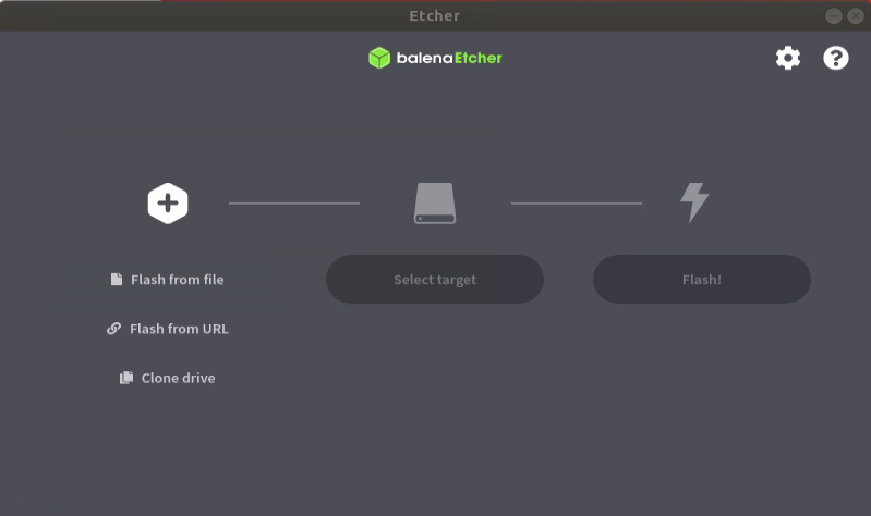
If you downloaded the version of balenaEtcher that needs to be installed, please install it first and then use it. If you downloaded the Portable version of balenaEtcher, just double-click to open it. The balenaEtcher interface after opening is as shown below.


|
If the following error is prompted when opening balenaEtcher:  Please select balenaEtcher, right-click, and select Run as administrator.  |
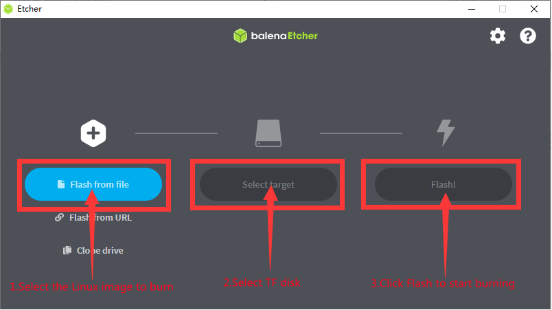
The specific steps to use balenaEtcher to burn a Linux image are as follows
a. First select the path of the Linux image file to be burned.
b. Then select the drive letter of the TF card
c. Finally click Flash and it will start burning the Linux image to the TF card.
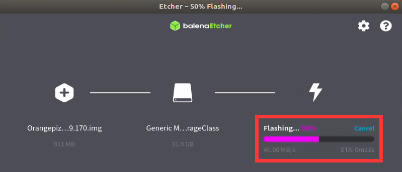
The interface displayed during the process of burning the Linux image by balenaEtcher is as shown in the figure below. In addition, the progress bar displays purple to indicate that the Linux image is being burned into the TF card.
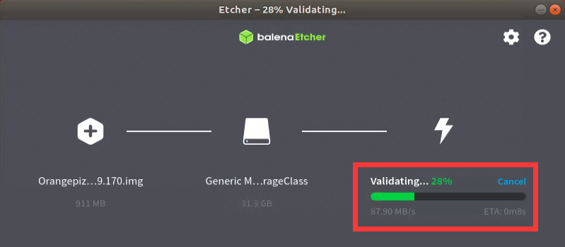
After the Linux image is burned, balenaEtcher will also verify the image burned into the TF card by default to ensure that there are no problems during the burning process. As shown in the figure below, a green progress bar indicates that the image has been burned, and balenaEtcher is verifying the burned image.
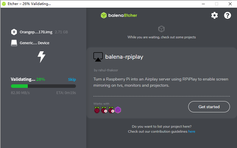
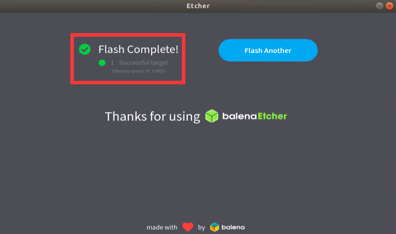
After successful burning, the display interface of balenaEtcher is as shown below. If the green indicator icon is displayed, it means that the image burning is successful. At this time, you can exit balenaEtcher, then pull out the TF card and insert it into the TF card slot of the development board for use.


How to burn Linux image using Win32Diskimager
First prepare a TF card with 8GB or larger capacity. The transmission speed of the TF card must be class10 or above. It is recommended to use TF cards from SanDisk and other brands.
Then use the card reader to insert the TF card into the computer
Then format the TF card
- You can use the SD Card Formatter software to format the TF card. Its download address is:
https://www.sdcard.org/downloads/formatter/eula_windows/SDCardFormatterv5_WinEN.zip
After downloading, just unzip and install it, and then open the software.
If only the TF card is inserted into the computer, the drive letter of the TF card will be displayed in the "Select card" column. If multiple USB storage devices are inserted into the computer, you can select the drive letter corresponding to the TF card through the drop-down box.
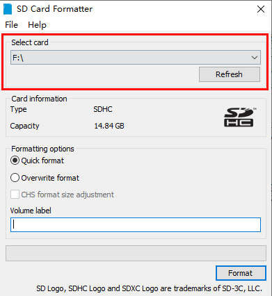
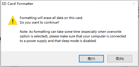
Then click "Format". A warning box will pop up before formatting. After selecting "Yes (Y)", formatting will begin.
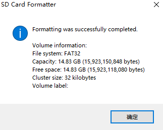
After formatting the TF card, the information shown in the picture below will pop up, click OK.


Download the compressed package of the Linux operating system image file you want to burn from the Orange Pi information download page, and then use the decompression software to decompress it. In the decompressed file, the file ending with ".img" is the image file of the operating system. The size is generally above 1GB
Use Win32Diskimager to burn the Linux image to the TF card
- The download page of Win32Diskimager is
http://sourceforge.net/projects/win32diskimager/files/Archive/
After downloading, you can install it directly. The Win32Diskimager interface is as follows
a) First select the path to the image file
b) Then confirm that the drive letter of the TF card is consistent with what is displayed in the "Device" column
c) Finally click "Write" to start burning
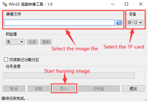
After the image writing is completed, click the "Exit" button to exit. Then you can pull out the TF card and insert it into the development board to start.

Method to burn Linux image to TF card based on Ubuntu PC
|
Note that the Linux image mentioned here specifically refers to the Linux distribution image such as Debian or Ubuntu downloaded from the Orange Pi information download page. Ubuntu PC refers to the personal computer with the Ubuntu system installed. |
- First prepare a TF card with 8GB or larger capacity. The transmission speed of the TF card must be class10 or above. It is recommended to use TF cards from SanDisk and other brands.
- Then use the card reader to insert the TF card into the computer
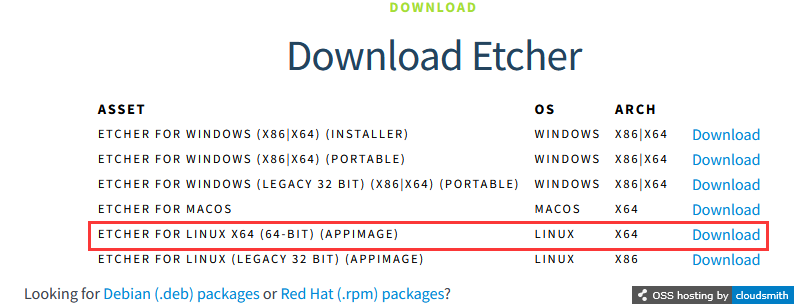
- Download the balenaEtcher software, the download address is
After entering the balenaEtcher download page, click the green download button to jump to the software download place.
Then choose to download the Linux version of the software
Download the compressed package of the Linux operating system image file you want to burn from the Orange Pi information download page, and then use the decompression software to decompress it. In the decompressed file, the file ending with ".img" is the image file of the operating system. The size is generally above 1GB. The decompression command for the compressed package ending in 7z is as follows:
test@test:~$ 7z x orangepizero2w_1.0.0_ubuntu_focal_desktop_linux6.1.31.7z
test@test:~$ ls orangepizero2w_1.0.0_ubuntu_focal_desktop_linux6.1.31.*
orangepizero2w_1.0.0_ubuntu_focal_desktop_linux6.1.31.7z
orangepizero2w_1.0.0_ubuntu_focal_desktop_linux6.1.31.sha #Checksum file
orangepizero2w_1.0.0_ubuntu_focal_desktop_linux6.1.31.img #Image file
After decompressing the image, you can first use the sha256sum -c *.sha command to calculate whether the checksum is correct. If it prompts that it is successful, it means that the downloaded image is correct, and you can burn it to the TF card with confidence. If it prompts that the checksum does not match, it means There is a problem with the downloaded image, please try downloading again
test@test:~$ sha256sum -c *.sha
orangepizero2w_1.0.0_ubuntu_focal_desktop_linux6.1.31.img: successful
Then double-click balenaEtcher-1.14.3-x64.AppImage on the graphical interface of Ubuntu PC to open balenaEtcher (no installation required). The interface after balenaEtcher is opened is as shown below
The specific steps to use balenaEtcher to burn a Linux image are as follows
a. First select the path of the Linux image file to be burned.
b. Then select the drive letter of the TF card
c. Finally click Flash and it will start burning the Linux image to the TF card.
The interface displayed during the process of burning the Linux image by balenaEtcher is as shown in the figure below. In addition, the progress bar displays purple to indicate that the Linux image is being burned into the TF card.
After the Linux image is burned, balenaEtcher will also verify the image burned into the TF card by default to ensure that there are no problems during the burning process. As shown in the figure below, a green progress bar indicates that the image has been burned, and balenaEtcher is verifying the burned image.
After successful burning, the display interface of balenaEtcher is as shown below. If a green indicator icon is displayed, it means that the image burning is successful. At this time, you can exit balenaEtcher, then pull out the TF card and insert it into the TF card slot of the development board for use.


Method of burning Android image to TF card
|
The Android image of the development board can only be burned to the TF card using the PhoenixCard software under the Windows platform. The version of the PhoenixCard software must be PhonixCard-4.2.8. Please do not use software to burn Linux images, such as Win32Diskimager or balenaEtcher to burn Android images. In addition, PhoenixCard software does not have versions for Linux and Mac platforms, so it is impossible to burn Android images to TF cards under Linux and Mac platforms. |
First, please make sure that Microsoft Visual C++ 2008 Redistrbutable - x86
is installed on your Windows system.
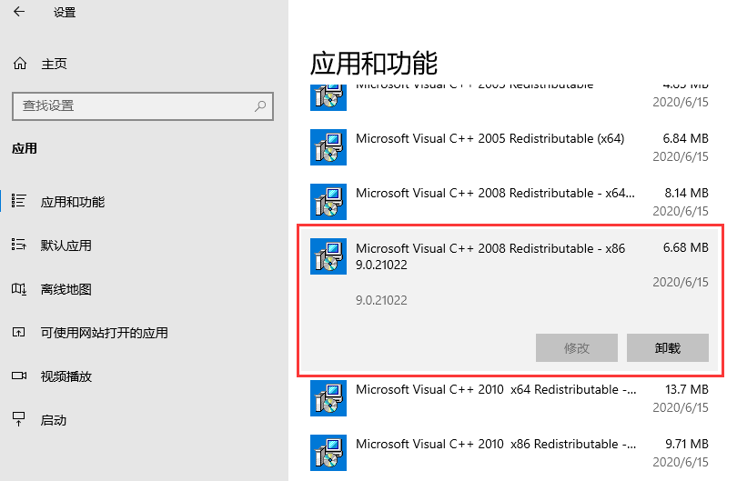
If Microsoft Visual C++ 2008 Redistrbutable - x86 is not installed, using PhoenixCard to format the TF card or burn the Android image will prompt the following error
Microsoft Visual C++ 2008 Redistrbutable - x86 installation package can be downloaded from the official tool of Orange Pi Zero 2w, or you can download it from Microsoft's official website

Then prepare a TF card with 8GB or larger capacity. The transmission speed of the TF card must be class10 or above. It is recommended to use TF cards from SanDisk and other brands.
Then use the card reader to insert the TF card into the computer
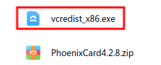
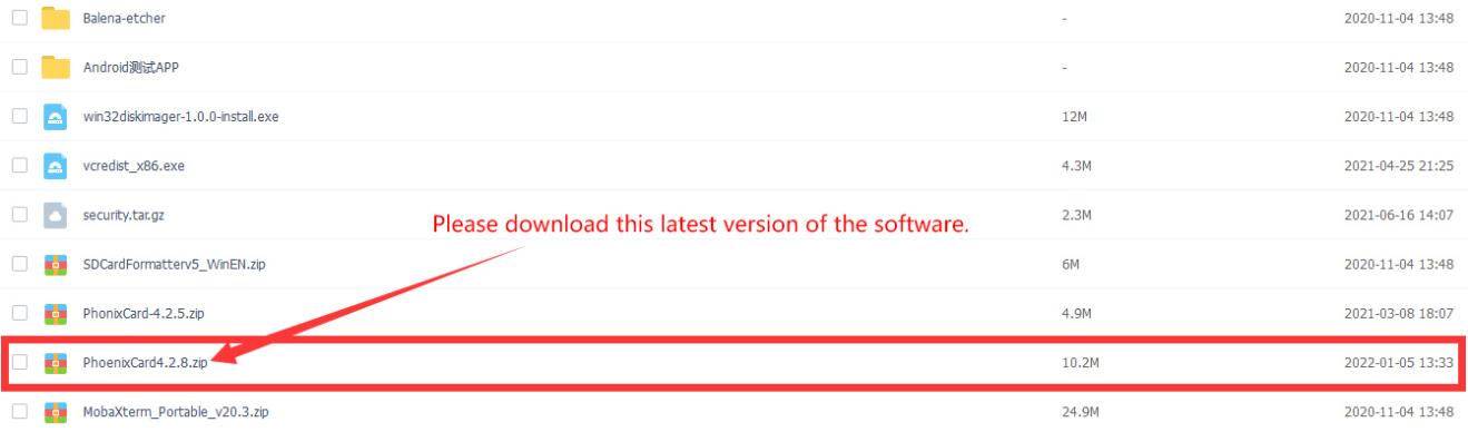
Download the Android image and PhoenixCard burning tool from the Orange Pi download page. Please ensure that the version of the PhonenixCrad tool is PhonixCard-4.2.8. Please do not use PhonixCard software with a version lower than 4.2.8 to burn the Android image. Low There may be problems with the Android image programmed with this version of PhonixCard tool.
Then use decompression software to decompress the compressed package of the downloaded Android image. In the decompressed file, the file ending with ".img" is the Android image file, with a size of more than 1GB. If you don't know how to decompress the Android image compressed package, you can install a 360 compression software to decompress the image.

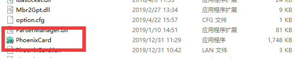
Then use decompression software to decompress PhonixCard4.2.8.zip. This software does not need to be installed. Just find PhoenixCard in the decompressed folder and open it.
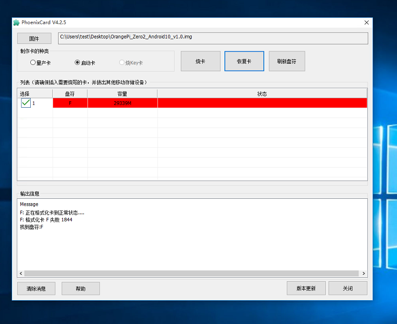
After opening PhoenixCard, if the TF card is recognized normally, the drive letter and capacity of the TF card will be displayed in the middle list. Please make sure that the displayed drive letter is consistent with the drive letter of the TF card you want to burn. If If there is no display, you can try to remove the TF card, or click the "Refresh Drive Letter" button in PhoenixCard.


After confirming the drive letter, format the TF card first and click the "Restore Card" button in PhoenixCard (if the "Restore Card" button is gray and cannot be pressed, you can click the "Refresh Drive Letter" button first)
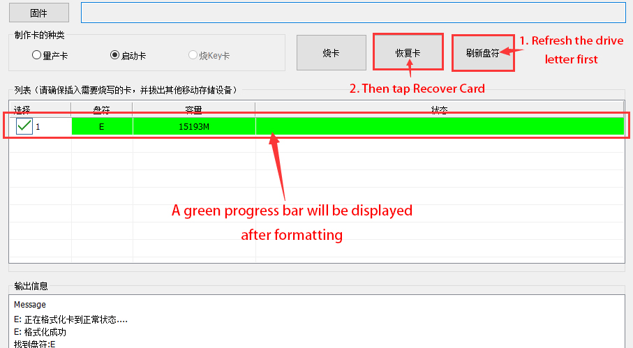
If there is a problem with formatting, please try to remove the TF card and then test again. If there is still a problem after re-inserting the TF card, you can restart the Windows computer or try another computer.
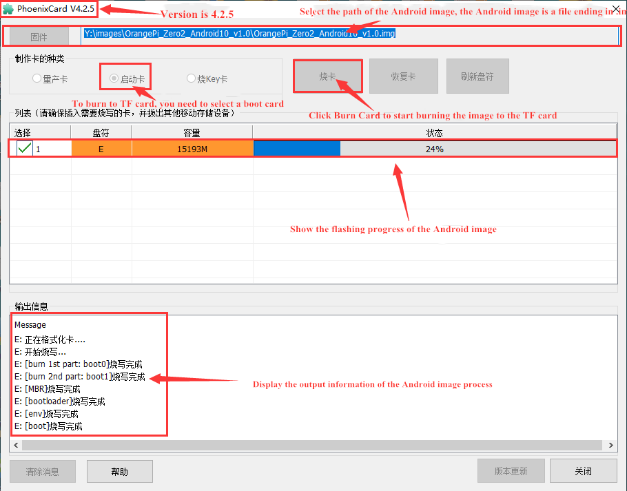
Then start writing the Android image to the TF card
a. First select the path to the Android image in the "Firmware" column
b. Select "Start Card" in "Card Type"
c. Then click the "Burn Card" button to start burning.
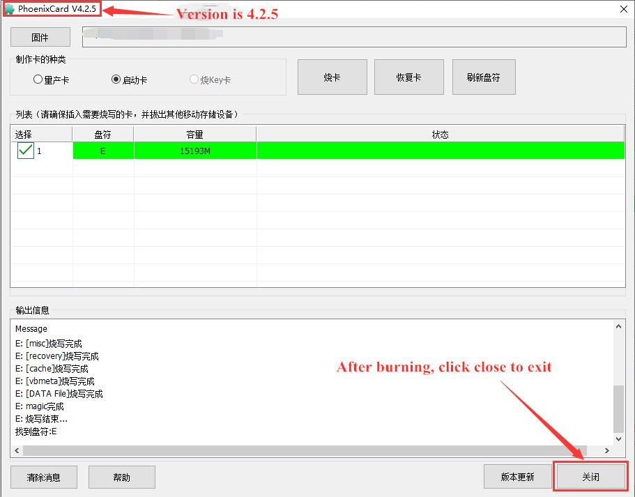
After burning, the display of PhoenixCard is as shown below. At this time, click the "Close" button to exit PhoenixCard, and then you can pull out the TF card from the computer and insert it into the development board to start.
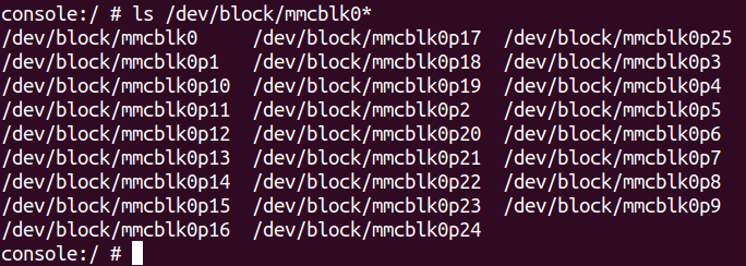
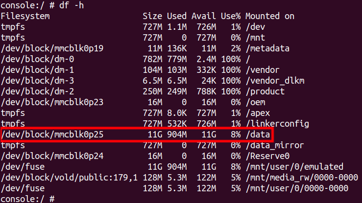
After burning the Android system, you can only see a 128 MB partition on the TF card in Windows. The displayed partition is as shown below (some computers may pop up more than twenty disk partitions, but they can only open the 128 MB one. partition), please note that this is normal, please do not think that the TF card is burned out. The reason for this is that there are more than twenty partitions in the Android system, but most of them cannot be recognized normally in the Windows system. At this time, please feel free to unplug the TF card and insert it into the development board to start.

After the Android system starts, you can use the following command to see the twenty partitions in the TF card:
Using the df -h command, you can see that after burning the Android system on the 16GB TF card, there is about 11 GB of space available (not all of the more than twenty partitions will be mounted to the Android system, focus on these to see to the partition you want to reach).


Instructions for using micro-linux system in onboard SPI Flash
There is a 16MB SPI Flash on the development board, and its location is shown in the figure below:

A micro Linux system is programmed into SPI Flash by default. This system is mainly used to prove that the development board can start normally. After getting the development board, there is no need to burn the system into the TF card. You only need to connect the Type-C power supply to the development board to start the micro Linux system in the SPI Flash. The main functions of this system are:
After booting into the kernel, the green LED light will flash;
If the development board is connected to an HDMI screen, after the system startup is completed, the command line interface of the micro Linux system can be seen on the HDMI screen.
I would like to emphasize again that the micro Linux system in SPI Flash is only used to prove that the development board can start normally (you can light up the development board without burning the system). If you find that there are other problems with the system in SPI Flash (such as serial port Unable to log in), please ignore it.
If you want to use the development board normally, please burn Ubuntu, Debian and other Linux images or Android images to the TF card, and then use it.
Start the Orange Pie development board
- Insert the TF card with the burned image into the TF card slot of the Orange Pi development board.
- The development board has a Mini HDMI interface. You can connect the development board to a TV or HDMI monitor through a Mini HDMI to HDMI cable.
- If you purchase a 24-pin expansion board, you can connect the 24-pin expansion board to the 24-pin interface of the development board through a cable.
- Connect a USB mouse and keyboard to control the Orange Pi development board.
- Connect a high-quality power adapter with a 5V/2A (5V/3A is also available) USB Type C interface
Remember not to plug in a power adapter with a voltage output greater than 5V, as it will burn out the development board.
Many unstable phenomena during system power-on and startup are basically caused by power supply problems, so a reliable power adapter is very important. If you find that you are constantly restarting during the startup process, please replace the power supply or Type C data cable and try again.
Both Type-C interfaces on the development board can be used for power supply.
Then turn on the power adapter. If everything is normal, the system startup screen will be visible on the HDMI monitor.
If you want to view the output information of the system through the debugging serial port, please use the serial port cable to connect the development board to the computer. For the serial port connection method, please refer to the section on how to use the debugging serial port.
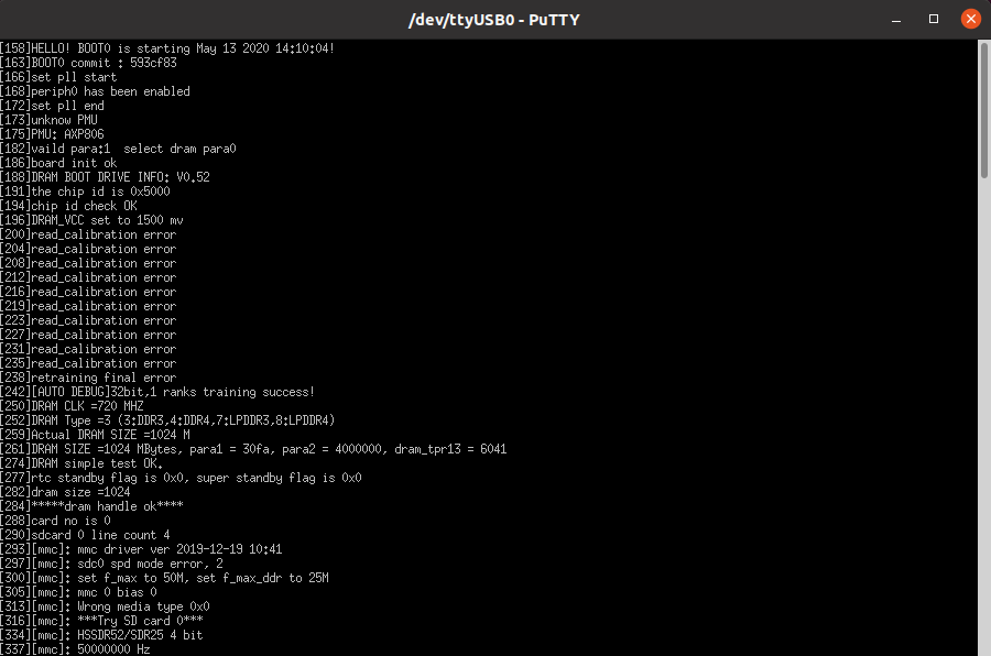
How to use the debugging serial port
Debug serial port connection instructions
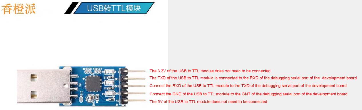
First, you need to prepare a 3.3v USB to TTL module, and then insert one end of the USB interface of the USB to TTL module into the USB interface of the computer.
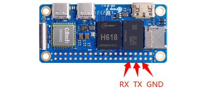
The corresponding relationship between the GND, TX and RX pins of the debugging serial port of the development board is shown in the figure below
Note: The pin header on the 40pin interface is not soldered by default, and you need to solder it yourself before it can be used.
The GND, TX and RX pins of the USB to TTL module need to be connected to the debugging serial port of the development board through Dupont lines.
Connect the GND of the USB to TTL module to the GND of the development board
Connect the RX of the USB to TTL module to the TX of the development board
Connect the TX of the USB to TTL module to the RX of the development board
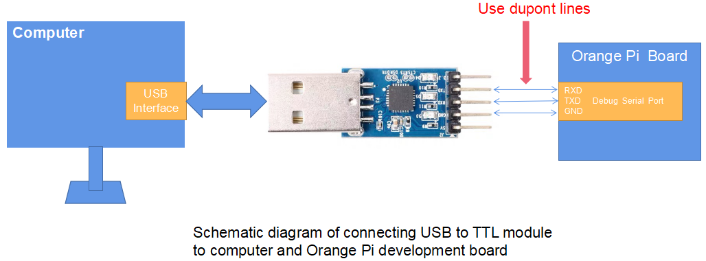
The schematic diagram of connecting the USB to TTL module to the computer and Orange Pi development board is as shown below
The TX and RX of the serial port need to be cross-connected. If you don't want to carefully distinguish the order of TX and RX, you can casually connect the TX and RX of the serial port first. If there is no output from the test serial port, then exchange the order of TX and RX, so that the There is a right order.


How to use the debugging serial port on Ubuntu platform
|
There are many serial port debugging software that can be used under Linux, such as putty, minicom, etc. The following demonstrates how to use putty. |
First insert the USB to TTL module into the USB interface of the Ubuntu computer. If the USB to TTL module is connected and recognized normally, you can see the corresponding device node name under /dev of the Ubuntu PC. Remember this node name and set the serial port later. software will be used
test@test:~$ ls /dev/ttyUSB*
/dev/ttyUSB0
Then use the following command to install putty on Ubuntu PC
test@test:~$ sudo apt update
test@test:~$ sudo apt install -y putty
Then run putty, remember to add sudo permissions
test@test:~$ sudo putty
After executing the putty command, the following interface will pop up
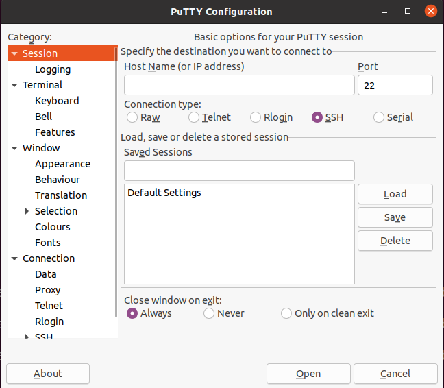
First select the serial port setting interface
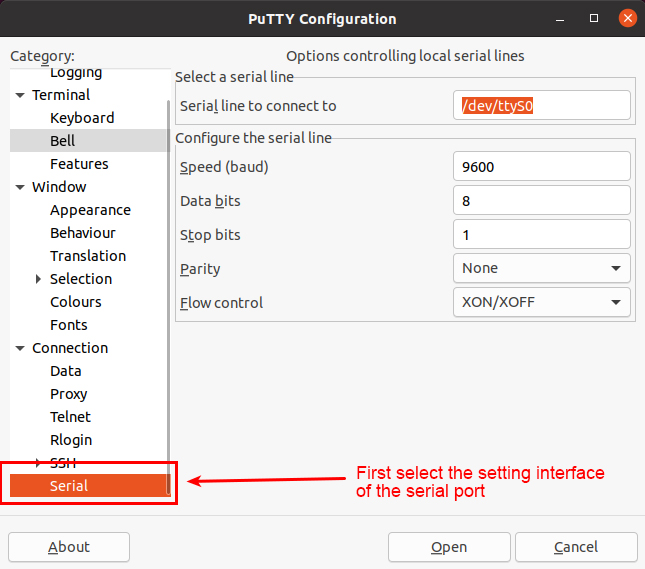
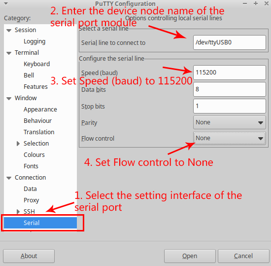
Then set the parameters of the serial port
Set the Serial line to connect to to /dev/ttyUSB0 (modify to the corresponding node name, usually /dev/ttyUSB0)
Set Speed(baud) to 115200 (baud rate of the serial port)
Set Flow control to None
After setting up the serial port setting interface, return to the Session interface.
First select Connection type as Serial
Then click the Open button to connect to the serial port
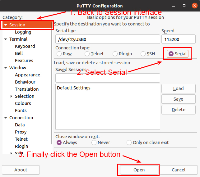
Then start the development board, and you can see the Log information output by the system from the open serial terminal.


How to use the debugging serial port on Windows platform
|
There are many serial port debugging software that can be used under Windows, such as SecureCRT, MobaXterm, etc. The following demonstrates how to use MobaXterm. This software has a free version and can be used without purchasing a serial number. |
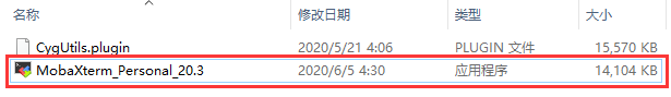
Download MobaXterm
Download MobaXterm URL as follows
Enter the MobaXterm download webpage and click GET XOBATERM > NOW!
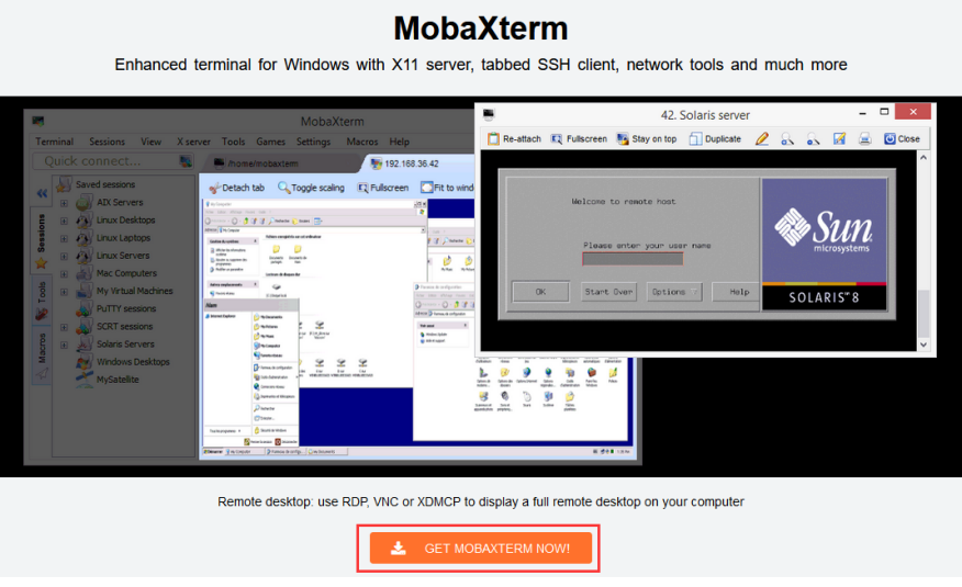
Then choose to download the Home version
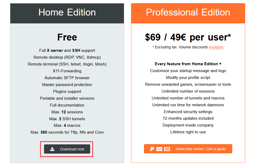
Then select the Portable version. There is no need to install it after downloading. You can open it directly and use it.
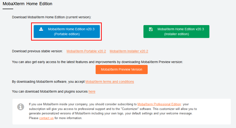
After downloading, use decompression software to decompress the downloaded compressed package to get the executable software of MobaXterm, and then double-click to open it.
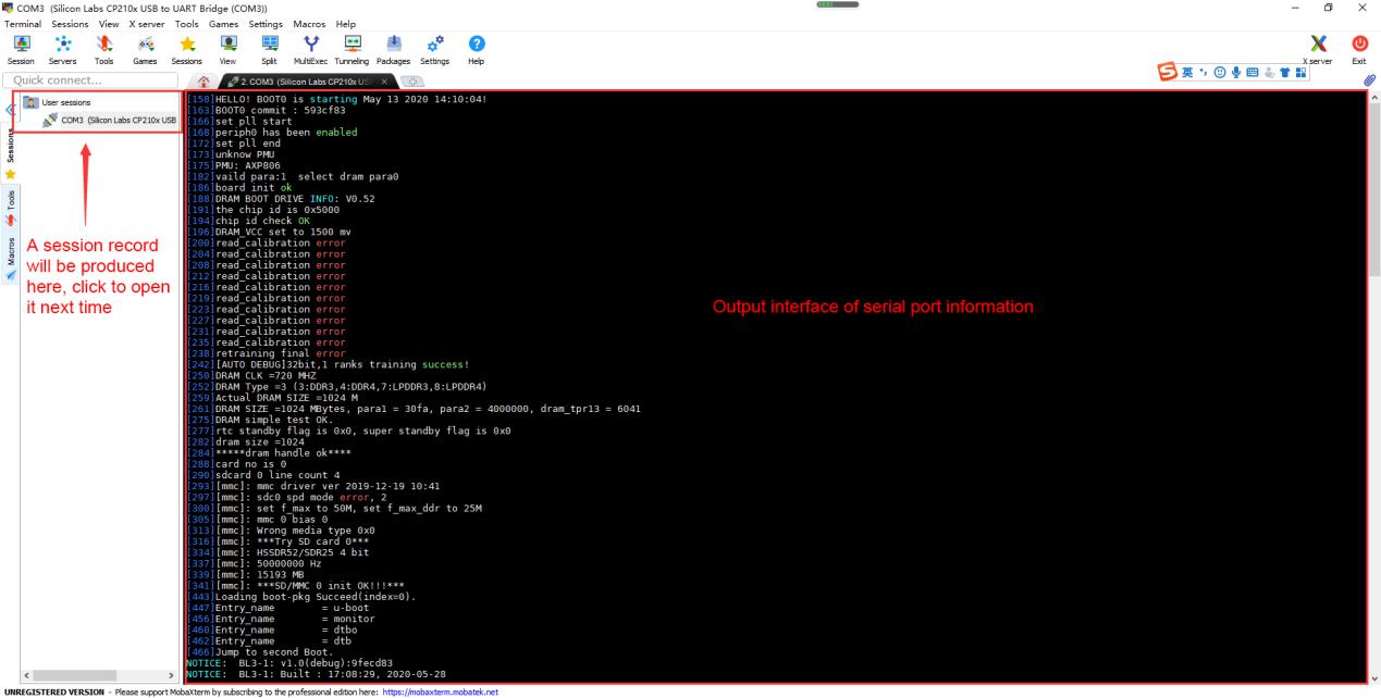
After opening the software, the steps to set up the serial port connection are as follows:
a. Open the session settings interface
b. Select the serial port type
c. Select the port number of the serial port (select the corresponding port number according to the actual situation). If you cannot see the port number, please use 360 Driver Master to scan and install the driver for the USB to TTL serial port chip.
d. Select the baud rate of the serial port to 115200
e. Finally click the "OK" button to complete the settings


After clicking the "OK" button, you will enter the following interface. At this time, start the development board and you can see the output information of the serial port.

Instructions for using the 5v pin in the 40pin interface of the development board for power supply
|
The power supply method we recommend for the development board is to use a 5V/2A or 5V/3A Type C interface power cord and plug it into the development board's Type C power interface. If you need to use the 5V pin in the 40-pin interface to power the development board, please ensure that the power cable used can meet the power supply requirements of the development board. If the use is unstable, please switch to Type C power supply. |
|
Note: The pin header on the 40pin interface is not soldered by default, and you need to solder it yourself before it can be used. |
First you need to prepare a power cord as shown in the picture below

The power cord shown in the picture above can be purchased on Taobao, please search and buy it yourself.
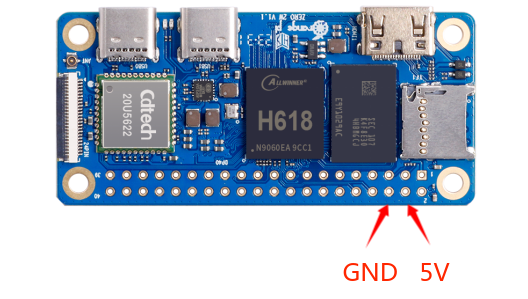
Use the 5V pin in the 40pin interface to power the development board. The power cord connection is as follows:
a. The USB-A port of the power cord shown in the picture above needs to be plugged into the 5V/2A or 5V/3A power adapter connector.
b. The red DuPont wire needs to be plugged into the 5V pin of the 40pin interface of the development board
c. The black DuPont wire needs to be plugged into the GND pin of the 40pin interface
d. The positions of the 5V pin and GND pin of the 40pin interface in the development board are as shown in the figure below. Remember not to connect them reversely.

Debian/Ubuntu Server and Xfce desktop system usage instructions
Supported linux image types and kernel versions
| Linux image type | Kernel version | Server version | desktop version |
| Ubuntu 20.04 - Focal | Linux5.4 | Support | Support |
| Debian 11 - Bullseye | Linux5.4 | Support | Support |
| Ubuntu 22.04 - Jammy | Linux6.1 | Support | Support |
| Debian 11 - Bullseye | Linux6.1 | Support | Support |
| Debian 12 - Bookworm | Linux6.1 | Support | Support |
After entering the download page of the corresponding development board on the Orange Pi data download page, you can see the following download options. In the description below, Ubuntu images and Debian images are generally referred to as Linux images.

The naming rules for Linux images are:
|
Development board model_version number_Linux distribution type_distribution code_server or desktop_kernel version |
a. Development board models: all are orangepizero2w. The model names of different development boards are generally different. Before burning the image, please make sure that the model name of the selected image matches the development board.
b. Version number: such as 1.x.x, this version number will increase with the update of the mirror function. In addition, the last number of the version number of the development board Linux mirror is an even number.
c. Type of Linux distribution: Ubuntu and Debian are currently supported. Since Ubuntu is derived from Debian, there is not much difference in usage between the two systems. However, there are still slight differences in the default configuration of some software and the use of commands. In addition, Ubuntu and Debian each maintain their own supported software repositories, and there are also slight differences in the supported installable software packages. These need to be used and experienced in person to have a deeper understanding. For more details, please refer to the official documentation provided by Ubuntu and Debian.
d. Release codename: Used to distinguish different versions of specific Linux distributions such as Ubuntu or Debian. Among them, focal and jammy are both Ubuntu distributions. focal means Ubuntu20.04 and jammy means Ubuntu22.04. The biggest difference between different versions is that the software in the software warehouse maintained by the new version of Ubuntu system is much better than that of the old version of Ubuntu system. The ones in it should be new, such as Python and GCC compilation tool chains. bullseye is the specific version code name of Debian, bullseye means Debian11, and bookworm means Debian12.
e. Server or desktop: Used to indicate whether the system has a desktop environment. If it is server, it means that the system does not have a desktop environment installed. The storage space and resources occupied by the image are relatively small. The command line is mainly used to operate the control system. If it is desktop_xfce, it means that the system has the XFCE desktop environment installed by default. The image takes up a lot of storage space and resources. You can connect a monitor, mouse and keyboard to operate the operating system through the interface. Of course, the desktop version of the system can also be operated through the command line like the server version of the system.
f. Kernel version: used to indicate the version number of the linux kernel. Currently, linux5.4 and linux6.1 are supported.
Linux kernel driver adaptation situation
| Board functions | Linux5.4 | Linux6.1 |
| HDMI video | OK | OK |
| HDMI audio | OK | OK |
| Type-C USB2.0 x 2 | OK | OK |
| TF card startup | OK | OK |
| WIFI | OK | OK |
| Bluetooth | OK | OK |
| USB Camera | OK | OK |
| LED Light | OK | OK |
| 40pin GPIO | OK | OK |
| 40pin I2C | OK | OK |
| 40pin SPI | OK | OK |
| 40pin UART | OK | OK |
| 40pin PWM | OK | OK |
| Temperature Sensor | OK | OK |
| Hardware watchdog | OK | OK |
| Mali GPU | NO | NO |
| Video codec | NO | NO |
| 24pin expansion board function | Linux5.4 | Linux6.1 |
| 100M network port | OK | OK |
| 100M Ethernet port light | OK | OK |
| USB2.0 HOST x 2 | OK | OK |
| Infrared reception | OK | OK |
| Headphone audio playback | OK | OK |
| On/off button | OK | OK |
| LRADC custom buttons x 2 | OK | OK |
| TV-OUT | NO | NO |
Linux command format description in this manual
All commands that need to be entered in the Linux system in this manual will be enclosed in the following boxes
As shown below, the content in the yellow box indicates content that requires special attention, except for the commands inside.
Description of the prompt type before the command
The prompt in front of the command refers to the red part in the box below. This part is not part of the Linux command. Therefore, when entering commands in the Linux system, please do not also enter the content in the red font.
orangepi@orangepi:~$ sudo apt update
root@orangepi:~# vim /boot/boot.cmd
test@test:~$ ssh root@192.168.1.xxx
root@test:~# ls
root@orangepi:~$ prompt indicates that this command is entered in the Linux system of the development board. The $ at the end of the prompt indicates that the current user of the system is an ordinary user. When executing a privileged command, sudo needs to be added.
root@orangepi:~# The prompt indicates that this command is entered in the Linux system of the development board. The # at the end of the prompt indicates that the current user of the system is the root user and can execute any command you want to execute.
test@test:~$ prompt indicates that this command was entered in the Ubuntu PC or Ubuntu virtual machine, not the Linux system of the development board. The $ at the end of the prompt indicates that the current user of the system is an ordinary user. When executing privileged commands, sudo needs to be added.
root@test:~# prompt indicates that this command is entered in the Ubuntu PC or Ubuntu virtual machine, not the Linux system of the development board. The # at the end of the prompt indicates that the current user of the system is the root user and can execute any command you want to execute.
What are the commands that need to be entered?
As shown below, the bold black part is the command that needs to be input. The content below the command is the output content (some commands have output, and some may not output). This part of the content does not need to be input.
root@orangepi:~# cat /boot/orangepiEnv.txt
verbosity=7
bootlogo=false
console=serial
As shown below, some commands that cannot be written in one line will be placed on the next line. As long as the black and bold parts are the commands that need to be entered. When these commands are entered into one line, the "\" at the end of each line needs to be removed. This is not part of the command. In addition, different parts of the command have spaces, please don't miss them.
orangepi@orangepi:~$ echo \
"deb [arch=$(dpkg --print-architecture) \
signed-by=/usr/share/keyrings/docker-archive-keyring.gpg] \
https://download.docker.com/linux/debian \
$(lsb_release -cs) stable" | sudo tee /etc/apt/sources.list.d/docker.list > /dev/null
Linux system login instructions
Linux system default login account and password
| Account | Password |
| root | orangepi |
| orangepi | orangepi |
|
Note that when entering a password, the specific content of the entered password will not be displayed on the screen. Please do not think that there is any malfunction. Just press Enter after entering the password. |
|
When you are prompted for an incorrect password or there is a problem with the ssh connection, please note that as long as you are using the Linux image provided by Orange Pi, please do not suspect that the above password is incorrect, but look for other reasons. |
How to set up automatic login of Linux system terminal
The Linux system automatically logs in to the terminal by default. The default login user name is orangepi
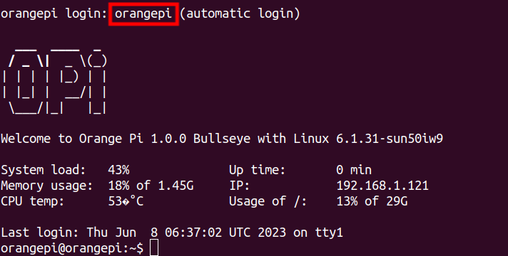
Use the following command to set the root user to automatically log in to the terminal
orangepi@orangepi:~$ sudo auto_login_cli.sh root
Use the following command to disable automatic login to the terminal
orangepi@orangepi:~$ sudo auto_login_cli.sh -d
Use the following command to set the orangepi user to automatically log in to the terminal again
orangepi@orangepi:~$ sudo auto_login_cli.sh orangepi

Instructions for automatic login of Linux desktop version system
The desktop version system will automatically log in to the desktop after startup without entering a password.

Run the following command to prevent the desktop system from automatically logging into the desktop.
orangepi@orangepi:~$ sudo disable_desktop_autologin.sh
Then restart the system and a login dialog box will appear. At this time, you need to enter a password to enter the system.


Setting method for automatic login of root user in Linux desktop system
Execute the following command to set the desktop version of the system to automatically log in using the root user
orangepi@orangepi:~$ sudo desktop_login.sh root
Then restart the system and you will automatically log in to the desktop as the root user.
Note that if you use the root user to log in to the desktop system, you cannot use pulseaudio in the upper right corner to manage audio devices.
Also please note that this is not a bug, because pulseaudio is not allowed to run under the root user.
Execute the following command to set up the desktop version of the system again to use the orangepi user to automatically log in
orangepi@orangepi:~$ sudo desktop_login.sh orangepi

How to disable the desktop in Linux desktop system
First enter the following command on the command line, please remember to add sudo permissions
orangepi@orangepi:~$ sudo systemctl disable lightdm.service
Then restart the Linux system and you will find that the desktop will not be displayed.
orangepi@orangepi:~$ sudo reboot
The command to reopen the desktop is as follows, please remember to add sudo permissions
orangepi@orangepi:~$ sudo systemctl start lightdm.service
orangepi@orangepi:~$ sudo systemctl enable lightdm.service
Onboard LED light test instructions
- There are two LED lights on the development board, one green light and one red light. The default display of the LED lights when the system is started is as follows:
Green light Red Light u-boot startup phase Turn off Bright Kernel boot to enter the system Flashing Bright
The green light on the development board can be controlled through software. The red light will be on continuously after power is turned on and cannot be controlled through software.
When you get the development board, you may find that even if the TF card with the system burned is not inserted into the development board, the green light will flash after connecting the power supply to the development board. This is because the 16MB SPI Flash on the development board is factory default. A miniature Linux system will be burned. This system will set the green light to flash after entering the kernel.
If the Linux system in the SPI Flash is cleared, then without inserting the TF card with the system programmed in it, you will only see a steady red light on the development board after turning on the power.
The method of setting the green light to turn on and off and flash is as follows:
Note that the following operations should be performed under the root user.
First enter the setting directory of the green light
root@orangepi:~# cd /sys/class/leds/green_led
The command to set the green light to stop flashing is as follows:
root@orangepi:/sys/class/leds/green_led# echo none > trigger
The command to set the green light to be always on is as > follows:
root@orangepi:/sys/class/leds/green_led# echo default-on > trigger
The command to set the green light flashing is as follows:
root@orangepi:/sys/class/leds/green_led# echo heartbeat > trigger
If you do not need the LED light to flash after powering on, you can use the following method to turn off the green light flashing
First run orangepi-config. Ordinary users remember to add sudo permissions.
orangepi@orangepi:~$ sudo orangepi-config
Then select System
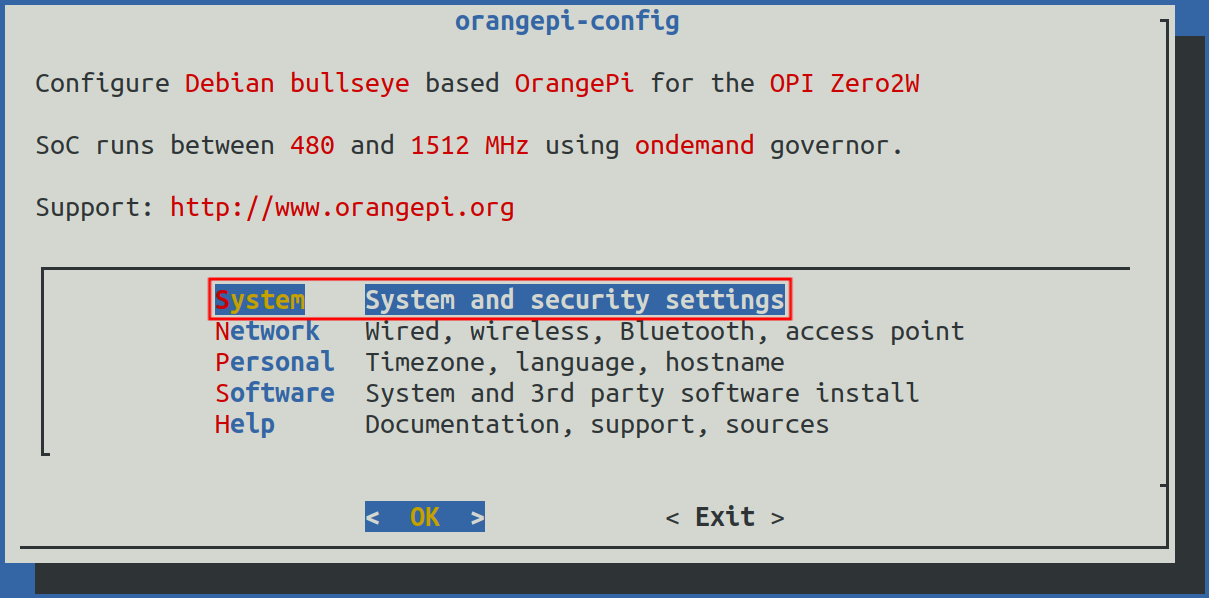
Then select Hardware
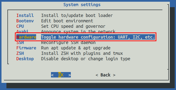
Then use the keyboard's arrow keys to locate the position shown in the picture below, and then use the space to select disable-leds

Then select <Save> to save

Then select <Back>

Then select <Reboot> to restart the system to make the configuration take effect.
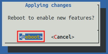
After restarting and entering the system, you can see that the green LED light on the development board will no longer light up.


Operation instructions for rootfs partition capacity of Linux system in TF card
The first startup will automatically expand the capacity of the rootfs partition in the TF card.
After burning the Linux image of the development board into the TF card, you can check the usage of the TF card capacity on the Ubuntu computer. The steps are as follows:
Note that failure to perform this step will not affect the automatic expansion of the Linux system of the development board. Here I just want to explain how to check the capacity of the TF card after burning the Linux image on the TF card.
First install the gparted software on your Ubuntu computer
test@test:~$ sudo apt install -y gparted
Then open gparted
test@test:~$ sudo gparted
After opening gparted, you can select the TF card in the upper right corner, and then you can see the usage of the TF card capacity.
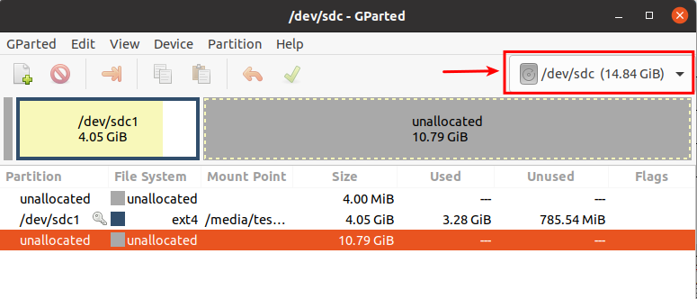
The picture above shows the situation of the TF card after burning the Linux desktop system. It can be seen that although the total capacity of the TF card is 16GB (displayed as 14.84GiB in GParted), the rootfs partition (/dev/ sdc1) Only 4.05GiB is actually allocated, leaving 10.79GiB unallocated
Then you can insert the TF card with the Linux system burned into the development board to start. When the TF card starts the Linux system for the first time, it will automatically call the orangepi-resize-filesystem script through the orangepi-resize-filesystem.service systemd service. Expansion of rootfs partition, so there is no need to manually expand it
After logging in to the system, you can use the df -h command to check the size of rootfs. If it is consistent with the actual capacity of the TF card, it means that the automatic expansion is running correctly.

|
orangepi@orangepi:~$ df -h Filesystem Size Used AvailUse% Mounted on |
After starting the Linux system for the first time, we can also remove the TF card from the development board and reinsert it into the Ubuntu computer, and then use gparted again to check the status of the TF card, as shown in the figure below, rootfs partition (/dev/ The capacity of sdc1) has been expanded to 14.69GiB
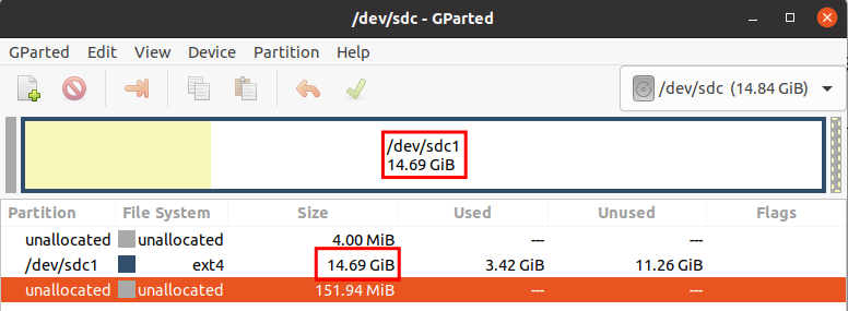
It should be noted that the Linux system has only one ext4 format partition and does not use a separate BOOT partition to store files such as kernel images, so there is no problem of BOOT partition expansion.

Method to prohibit automatic expansion of rootfs partition capacity in TF card
First, burn the Linux image of the development board into the TF card on the Ubuntu computer (Windows is not available), and then unplug and insert the TF card again.
Then the Ubuntu computer will usually automatically mount the partition of the TF card. If the automatic mounting is normal, use the ls command to see the following output.
test@test:~$ ls /media/test/opi_root/
bin boot dev etc home lib lost+found media mnt opt proc root run
sbin selinux srv sys tmp usr varThen switch the current user to the root user on the Ubuntu computer
test@test:~$ sudo -i
[sudo] test 的密码:
root@test:~#
Then enter the root directory of the Linux system in the TF card and create a new file named .no_rootfs_resize
root@test:~# cd /media/test/opi_root/
root@test:/media/test/opi_root/# cd root
root@test:/media/test/opi_root/root# touch .no_rootfs_resize
root@test:/media/test/opi_root/root# ls .no_rootfs*
.no_rootfs_resize
Then you can uninstall the TF card, then pull out the TF card and insert it into the development board to start. When the Linux system starts, when the .no_rootfs_resize file is detected in the /root directory, rootfs will not be automatically expanded.
After disabling the automatic expansion of rootfs, you can enter the Linux system and you can see that the total capacity of the rootfs partition is only 4GB (the image tested here is the desktop version), which is much smaller than the actual capacity of the TF card, indicating that the automatic expansion of rootfs has been successfully disabled.
orangepi@orangepi:~$ df -h
Filesystem Size Used AvailUse% Mounted on
udev925M 0925M 0% /dev
tmpfs 199M 3.2M 196M 2% /run
/dev/mmcblk0p14.0G 3.2G 686M 83% /
If you need to re-expand the capacity of the rootfs partition in the TF card, just execute the following command and then restart the Linux system of the development board.
Note, please execute the following command under the root user.
root@orangepi:~# rm /root/.no_rootfs_resize
root@orangepi:~# systemctl enable orangepi-resize-filesystem.service
root@orangepi:~# sudo reboot
After restarting, enter the Linux system of the development board again and you will see that the rootfs partition has been expanded to the actual capacity of the TF card.
root@orangepi:~$ df -h
Filesystem Size Used AvailUse% Mounted on
udev925M 0925M 0% /dev
tmpfs 199M 3.2M 196M 2% /run
/dev/mmcblk0p115G3.2G 12G 23% /
Method to manually expand the capacity of rootfs partition in TF card
|
If the total capacity of the TF card is large, such as 128GB, and you do not want the rootfs partition of the Linux system to use all the capacity of the TF card, you only want to allocate a part of the capacity, such as 16GB, to the Linux system, and then the remaining capacity of the TF card can be used for other purposes. use. Then you can use the content introduced in this section to manually expand the capacity of the rootfs partition in TF. |
First, burn the Linux image of the development board into the TF card on the Ubuntu computer (Windows is not available), and then unplug and insert the TF card again.
Then the Ubuntu computer will usually automatically mount the partition of the TF card. If the automatic mounting is normal, use the ls command to see the following output.
test@test:~$ ls /media/test/opi_root/
bin boot dev etc home lib lost+found media mnt opt proc root run
sbin selinux srv sys tmp usr varThen switch the current user to the root user on the Ubuntu computer
test@test:~$ sudo -i
[sudo] test 的密码:
root@test:~#
Then enter the root directory of the Linux system in the TF card and create a new file named .no_rootfs_resize
root@test:~# cd /media/test/opi_root/
root@test:/media/test/opi_root/# cd root
root@test:/media/test/opi_root/root# touch .no_rootfs_resize
root@test:/media/test/opi_root/root# ls .no_rootfs*
.no_rootfs_resize
Then install the gparted software on your Ubuntu computer
test@test:~$ sudo apt install -y gparted
Then open gparted
test@test:~$ sudo gparted
After opening gparted, you can select the TF card in the upper right corner, and then you can see the usage of the TF card capacity. The picture below shows the situation of the TF card after burning the Linux desktop system. It can be seen that although the total capacity of the TF card is 16GB (displayed as 14.84GiB in GParted), the rootfs partition (/dev/sdc1) Only 4.05GiB is actually allocated, leaving 10.79GiB unallocated
Then select the rootfs partition (/dev/sdc1)
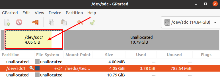
Right-click the mouse again to see the operation options shown in the picture below. If the TF card has been mounted, you first need to Umount the rootfs partition of the TF card.
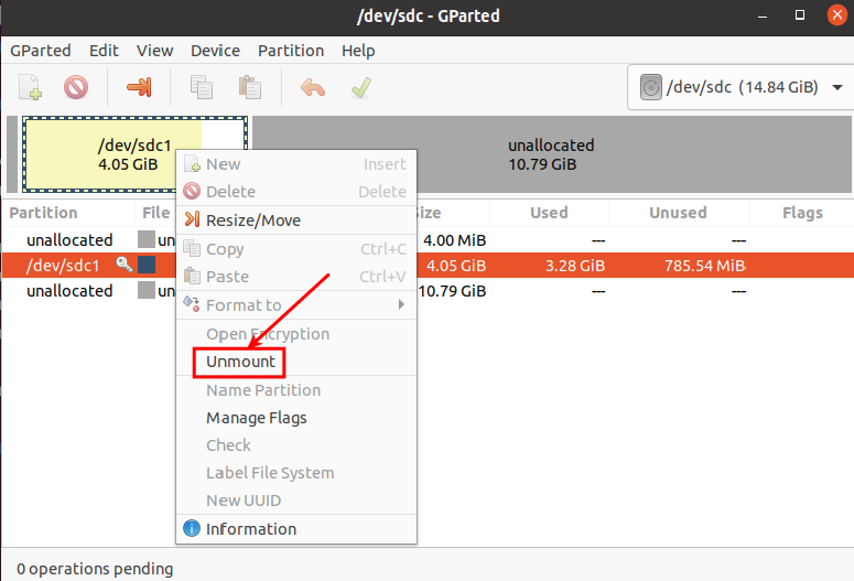
Then select the rootfs partition again, right-click, and select Resize/Move to start expanding the size of the rootfs partition.
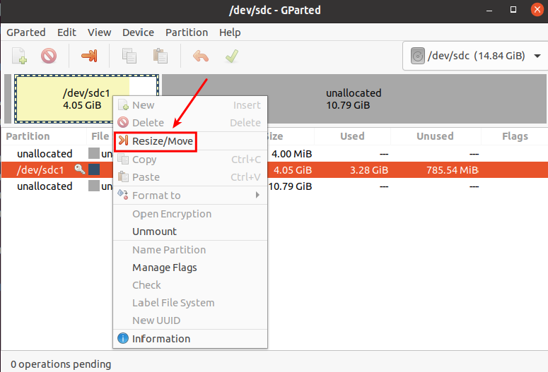
After the Resize/Move option is turned on, the following setting interface will pop up.
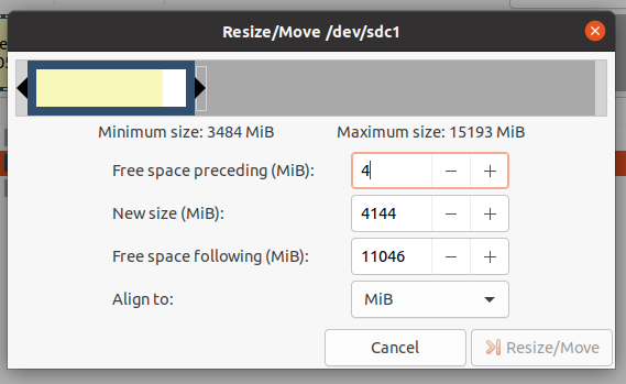
Then you can directly drag the position shown in the figure below to set the size of the capacity, or you can set the size of the rootfs partition by setting the number in New size(MiB)
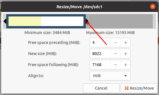
After setting the capacity, click Resize/Move in the lower right corner.
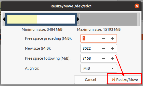
After final confirmation, click the green √ shown in the picture below.
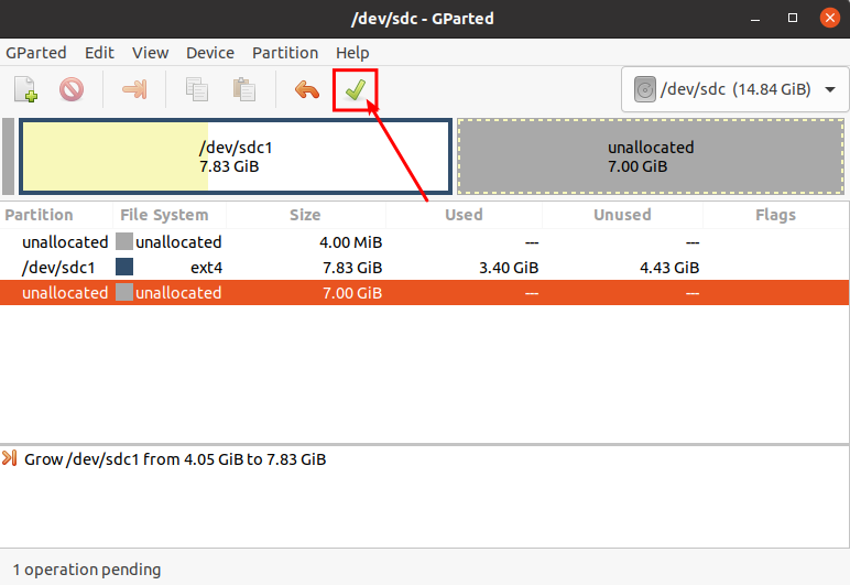
Then select Apply, and the capacity expansion of the rootfs partition will officially begin.
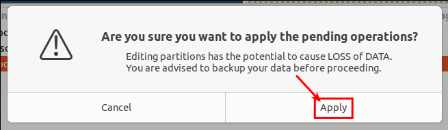
After the expansion is completed, click Close to close it.
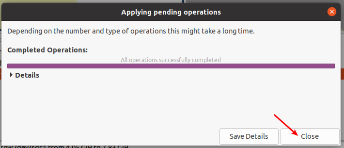
Then you can unplug the TF card and insert it into the development board to start. After entering the Linux system of the development board, if you use the df -h command to see that the size of the rootfs partition is consistent with the size set previously, it means manual Expansion successful
root@orangepi:~# df -h
Filesystem Size Used AvailUse% Mounted on
udev925M 0925M 0% /dev
tmpfs 199M 3.2M 196M 2% /run
/dev/mmcblk0p17.7G 3.2G 4.4G 42% /


Method to reduce the capacity of rootfs partition in TF card
|
After configuring the application or other development environment in the Linux system of the TF card, if you want to back up the Linux system in the TF card, you can use the method in this section to reduce the size of the rootfs partition first, and then start the backup. |
First, insert the TF card you want to operate on your Ubuntu computer (not Windows)
Then install the gparted software on your Ubuntu computer
test@test:~$ sudo apt install -y gparted
Then open gparted
test@test:~$ sudo gparted
After opening gparted, you can select the TF card in the upper right corner, and then you can see the usage of the TF card capacity.
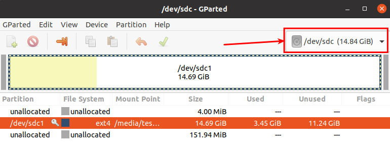
Then select the rootfs partition (/dev/sdc1)
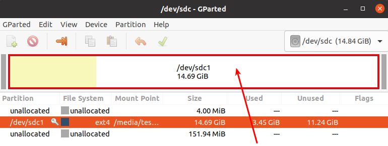
Right-click the mouse again to see the operation options shown in the picture below. If the TF card is already mounted, you first need to Umount the rootfs partition of the TF card.
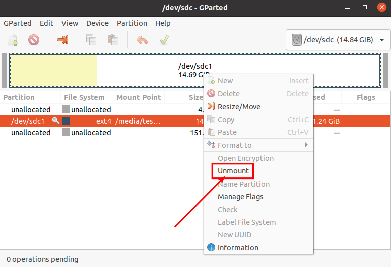
Then select the rootfs partition again, right-click the mouse, and select Resize/Move to start setting the size of the rootfs partition.
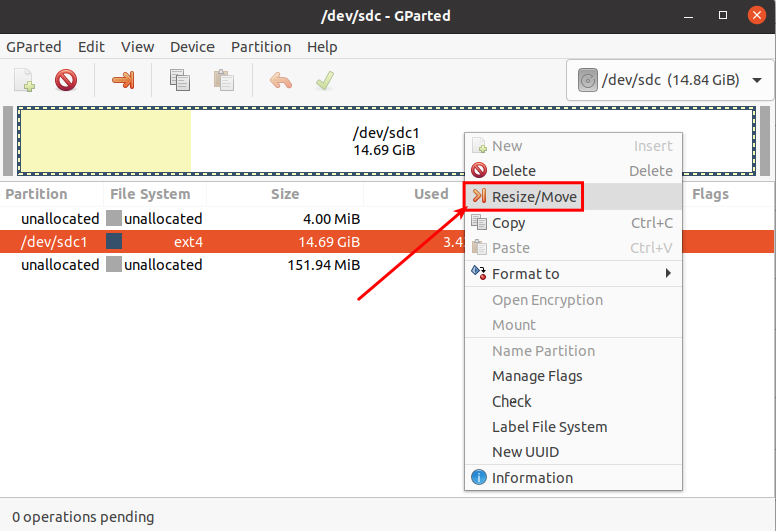
After the Resize/Move option is turned on, the following setting interface will pop up.
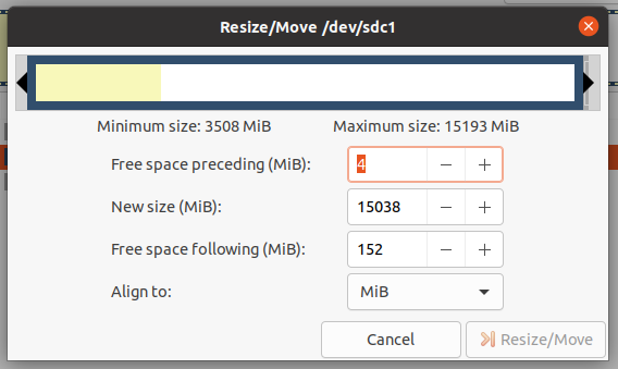
Then you can directly drag the position shown in the figure below to set the size of the capacity, or you can set the size of the rootfs partition by setting the number in New sieze(MiB)
After setting the capacity, click Resize/Move in the lower right corner.
After final confirmation, click the green √ as shown in the picture below.
Then select Apply, and the capacity expansion of the rootfs partition will officially begin.
After the expansion is completed, click Close to close it.
Then you can unplug the TF card and insert it into the development board to start. After entering the Linux system of the development board, if you use the df -h command, you can see that the size of the rootfs partition is consistent with the size set previously, which means it has been reduced capacity success
root@orangepi:~# df -h
Filesystem Size Used AvailUse% Mounted on
udev925M 0925M 0% /dev
tmpfs 199M 3.2M 196M 2% /run
/dev/mmcblk0p17.7G 3.2G 4.4G 42% /


24Pin expansion board interface pin description
Please refer to the figure below for the order of the interface pins of the 24-pin expansion board of the development board.
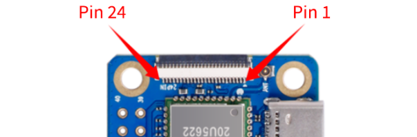
The schematic diagram of the 24pin expansion board interface of the development board is as follows
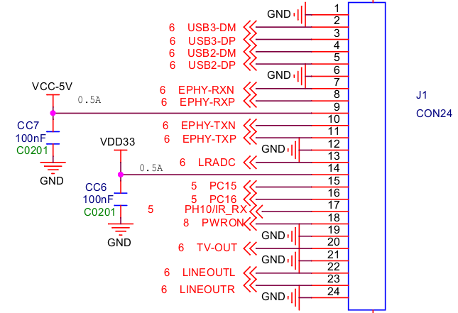
The way to connect the expansion board to the development board is as follows. Please pay attention to the forward and reverse directions of the cable and do not plug it in backwards.
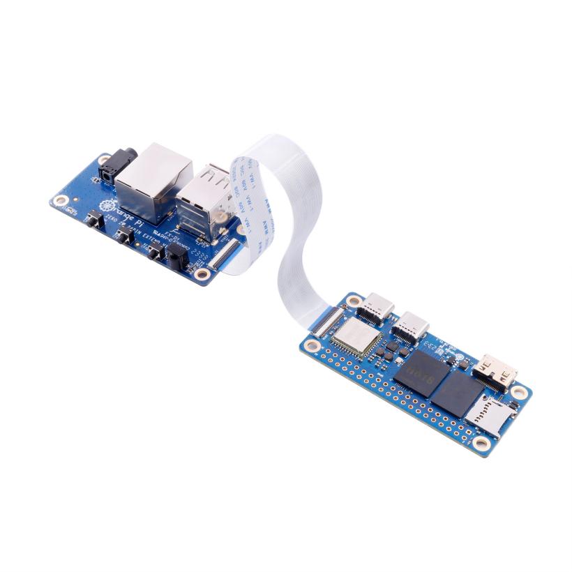
The functions that the expansion board can expand include:
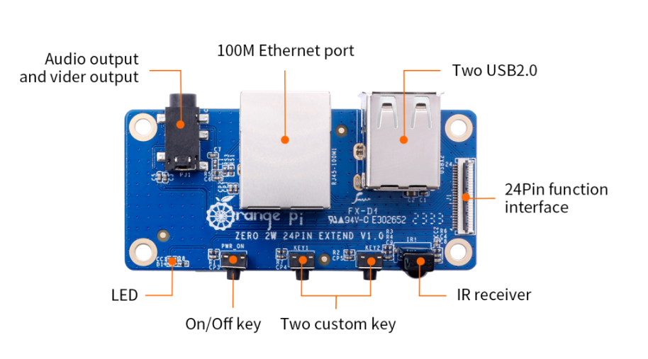


| 1 | 100M network port | Used to connect to a wired network to access the Internet |
| 2 | Analog audio and video output interface | In Linux system, it can be used to connect headphones to play music, but the TV-OUT function cannot be used. |
| 3 | USB 2.0 Host x 2 | For connecting USB keyboard, mouse and USB storage devices |
| 4 | Infrared receiving function | Currently it is mainly used in Android systems, and Linux systems are mainly adapted to kernel drivers. |
| 5 | On/off button | Used to turn off or turn on the development board |
| 6 | LRADC custom buttons x 2 | The default settings of the Linux system are KEY_1 (Number 1 key) and KEY_ENTER (Enter key), which can be customized as other function keys by modifying the dts configuration. |
- The adaptation of Linux5.4 and Linux6.1 systems to expansion boards is shown in the following table
| 24pin expansion board function | Linux5.4 | Linux6.1 |
| 100M network port | OK | OK |
| 100M Ethernet port light | OK | OK |
| USB2.0 HOST x 2 | OK | OK |
| Infrared reception | OK | OK |
| Headphone audio playback | OK | OK |
| On/off button | OK | OK |
| LRADC custom buttons x 2 | OK | OK |
| TV-OUT | NO | NO |
How to use the two LRADC buttons on the 24pin expansion board
There are two LRADC buttons on the 24pin expansion board, and their locations are as shown in the figure below:
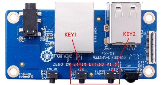
In the Linux system, the default key values of KEY1 and KEY2 are

| Linux kernel | KEY1 | KEY2 |
| Linux5.4 | KEY_1, the number 1 on the keyboard | KEY_ENTER, the enter key |
| Linux6.1 | KEY_1, the number 1 on the keyboard | KEY_ENTER, the enter key |
Through the evtest command, we can check the key values reported after KEY1 and KEY2 are pressed.
linux5.4
orangepi@orangepizero2w:~$ evtest
No device specified, trying to scan all of /dev/input/event*
Not running as root, no devices may be available.
Available devices:
/dev/input/event0: sunxi-keyboard
/dev/input/event1: sunxi-ir
/dev/input/event2: axp2101-pek
/dev/input/event3: SONiX USB Keyboard
/dev/input/event4: SONiX USB Keyboard Consumer Control
/dev/input/event5: SONiX USB Keyboard System Control
/dev/input/event6: PixArt USB Optical Mouse
/dev/input/event7: BRLTTY 6.3 Linux Screen Driver Keyboard
Select the device event number [0-7]: 0 #You need to enter the serial number corresponding to sunxi-keyboard
Input driver version is 1.0.1
Input device ID: bus 0x19 vendor 0x1 product 0x1 version 0x100
Input device name: "sunxi-keyboard"
Supported events:
Event type 0 (EV_SYN)
Event type 1 (EV_KEY)
Event code 2 (KEY_1)
Event code 28 (KEY_ENTER)
Properties:
Testing ... (interrupt to exit)
#The following are the key values reported after pressing KEY1 and KEY2
Event: time 1693555298.132314, type 1 (EV_KEY), code 2 (KEY_1), value 1
Event: time 1693555298.132314, -------------- SYN_REPORT ------------
Event: time 1693555298.226071, type 1 (EV_KEY), code 2 (KEY_1), value 0
Event: time 1693555298.226071, -------------- SYN_REPORT ------------
Event: time 1693555298.601042, type 1 (EV_KEY), code 28 (KEY_ENTER), value 1
Event: time 1693555298.601042, -------------- SYN_REPORT ------------
Event: time 1693555298.710415, type 1 (EV_KEY), code 28 (KEY_ENTER), value 0
Event: time 1693555298.710415, -------------- SYN_REPORT ------------
linux6.1
orangepi@orangepizero2w:~$ evtest
No device specified, trying to scan all of /dev/input/event*
Not running as root, no devices may be available.
Available devices:
/dev/input/event0: axp20x-pek
/dev/input/event1: 5070800.lradc
/dev/input/event2: SONiX USB Keyboard
/dev/input/event3: SONiX USB Keyboard Consumer Control
/dev/input/event4: SONiX USB Keyboard System Control
/dev/input/event5: PixArt USB Optical Mouse
/dev/input/event6: sunxi-ir
Select the device event number [0-6]: 1 #You need to enter the serial number corresponding to 5070800.lradc
Input driver version is 1.0.1
Input device ID: bus 0x19 vendor 0x1 product 0x1 version 0x100
Input device name: "5070800.lradc"
Supported events:
Event type 0 (EV_SYN)
Event type 1 (EV_KEY)
Event code 2 (KEY_1)
Event code 28 (KEY_ENTER)
Properties:
Testing ... (interrupt to exit)
#The following are the key values reported after pressing KEY1 and KEY2
Event: time 1694075818.810877, type 1 (EV_KEY), code 2 (KEY_1), value 1
Event: time 1694075818.810877, -------------- SYN_REPORT ------------
Event: time 1694075818.961345, type 1 (EV_KEY), code 2 (KEY_1), value 0
Event: time 1694075818.961345, -------------- SYN_REPORT ------------
Event: time 1694075819.536128, type 1 (EV_KEY), code 28 (KEY_ENTER), value 1
Event: time 1694075819.536128, -------------- SYN_REPORT ------------
Event: time 1694075819.705009, type 1 (EV_KEY), code 28 (KEY_ENTER), value 0
Event: time 1694075819.705009, -------------- SYN_REPORT ------------
If you need to modify the key values reported after KEY1 and KEY2 are pressed, you can use the following method:
There is a sun50i-h618-lradc-keys.dts file under the /usr/src/ path, through which we can define KEY1 and KEY2 as the desired key values.
orangepi@orangepizero2w:~$ cd /usr/src/
orangepi@orangepizero2w:/usr/src$ ls *.dts
sun50i-h618-lradc-keys.dts
The contents of the sun50i-h618-lradc-keys.dts file in the linux5.4 system are as follows:
a) KEY1 correspondence: modify key0 = <600 2>; where 2 is the number corresponding to the desired key value
b) KEY2 correspondence: modify key1 = <800 28>; where 28 is the number corresponding to the desired key value
orangepi@orangepizero2w:/usr/src$ sudo vim sun50i-h618-lradc-keys.dts
/dts-v1/;
/plugin/;
/ {
fragment@0 {
target = <&keyboard>;
__overlay__ {
status = "okay";
key0 = <600 2>;
key1 = <800 28>;
};
};
};
The contents of the c.linux6.1 system sun50i-h618-lradc-keys.dts file are as follows:
a) KEY1 corresponding: modify linux,code = <2>; the 2 in > it is the number corresponding to the desired key value
b) KEY2 correspondence: modify linux,code = <28>; the 28 > in it is the number corresponding to the desired key value
orangepi@orangepizero2w:/usr/src$ sudo vim sun50i-h618-lradc-keys.dts
/dts-v1/;
/plugin/;
/ {
fragment@0 {
target = <&r_lradc>;
__overlay__ {
status = "okay";
button-500 {
label = "KEY_1";
linux,code = <2>;
};
button-800 {
label = "KEY_ENTER";
linux,code = <28>;
};
};
};
};
For the key values that can be set, please refer to the macro definition in the input-event-codes.h header file. Its path in the kernel source code is:
orange-pi-5.4-sun50iw9/include/uapi/linux/input-event-codes.h
orange-pi-6.1-sun50iw9/include/uapi/linux/input-event-codes.h
After modification, use the orangepi-add-overlay command to add the sun50i-h618-lradc-keys.dts configuration to the system.
orangepi@orangepizero2w:/usr/src$ sudo orangepi-add-overlay sun50i-h618-lradc-keys.dts
Compiling the overlay
Copying the compiled overlay file to /boot/overlay-user/
Reboot is required to apply the changes
Then restart the system and the customized key values will take effect.
Network connection test
Ethernet port test
There is no wired network interface on the main board of the development board. We can expand the 100M wired network interface through a 24pin expansion board.
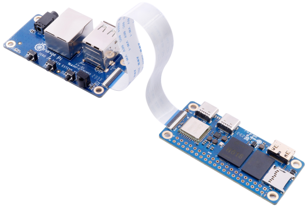
Then plug one end of the network cable into the Ethernet interface of the expansion board, and the other end of the network cable into the router, and make sure the network is smooth.
After the system starts, it will automatically assign an IP address to the Ethernet card through DHCP, and no other configuration is required.
The command to view the IP address in the Linux system of the development board is as follows:
Please do not copy the following commands. For example, the network node name in debian12 is end0, and the following command needs to be modified to ip a s end0.
orangepi@orangepi:~$ ip a s eth0
3: eth0: <BROADCAST,MULTICAST,UP,LOWER_UP> mtu 1500 qdisc pfifo_fast state UP group default qlen 1000
link/ether 5e:ac:14:a5:93:b3 brd ff:ff:ff:ff:ff:ff
inet 192.168.1.16/24 brd 192.168.1.255 scope global dynamic noprefixroute eth0
valid_lft 259174sec preferred_lft 259174sec
inet6 240e:3b7:3240:c3a0:e269:8305:dc08:135e/64 scope global dynamic noprefixroute
valid_lft 259176sec preferred_lft 172776sec
inet6 fe80::957d:bbbd:4928:3604/64 scope link noprefixroute
valid_lft forever preferred_lft forever
There are three ways to check the IP address after the development board is started:
1. Connect the HDMI display, then log in to the system and use the ip a s eth0 command to check the IP address.
2. Enter the ip a s eth0 command in the debugging serial terminal to view the IP address.
3. If there is no debugging serial port or HDMI display, you can also check the IP address of the development board's network port through the router's management interface. However, with this method, people often fail to see the IP address of the development board. If you can't see it, here's how to debug it:
A) First check whether the Linux system has started normally. If the green light of the development board flashes, it usually means that it has started normally. If only the red light is on, or the red and green lights are not on, it means that the system has not started normally;
B) Check whether the network cable is plugged in tightly, or try another network cable;
C) Try another router (I have encountered many problems with routers, such as the router being unable to assign an IP address normally, or the IP address being assigned normally but not being visible in the router);
D) If there is no router to replace, you can only connect an HDMI display or use the debugging serial port to check the IP address.
In addition, it should be noted that the development board's DHCP automatic allocation of IP addresses does not require any settings.
The command to test network connectivity is as follows. The ping command can be interrupted by pressing the Ctrl+C shortcut key.
Please do not copy the following commands. For example, the network node name in debian12 is end0. The following command needs to be modified to ping www.baidu.com -I end0.
orangepi@orangepi:~$ ping www.baidu.com -I eth0
PING www.a.shifen.com (14.215.177.38) from 192.168.1.12 eth0: 56(84) bytes of data.
64 bytes from 14.215.177.38 (14.215.177.38): icmp_seq=1 ttl=56 time=6.74 ms
64 bytes from 14.215.177.38 (14.215.177.38): icmp_seq=2 ttl=56 time=6.80 ms
64 bytes from 14.215.177.38 (14.215.177.38): icmp_seq=3 ttl=56 time=6.26 ms
64 bytes from 14.215.177.38 (14.215.177.38): icmp_seq=4 ttl=56 time=7.27 ms
^C
--- www.a.shifen.com ping statistics ---
4 packets transmitted, 4 received, 0% packet loss, time 3002ms
rtt min/avg/max/mdev = 6.260/6.770/7.275/0.373 ms
WIFI connection test
|
Please do not connect to WIFI by modifying the /etc/network/interfaces configuration file. There will be problems in connecting to the WIFI network in this way. |
Server version image connects to WIFI through commands
|
When the development board is not connected to Ethernet or HDMI display, but only to the serial port, it is recommended to use the commands demonstrated in this section to connect to the WIFI network. Because nmtui can only display characters in some serial port software (such as minicom) and cannot display the graphical interface normally. Of course, if the development board is connected to an Ethernet or HDMI display, you can also use the commands demonstrated in this section to connect to the WIFI network. |
First log in to the Linux system, there are three ways:
a. If the development board is connected to a network cable, you can remotely log in to the Linux system through ssh.
b. If the development board is connected to the debugging serial port, you can use the serial port terminal to log in to the Linux system.
c. If the development board is connected to an HDMI display, you can log in to the Linux system through the HDMI display terminal.
First use the nmcli dev wifi command to scan the surrounding WIFI hotspots
orangepi@orangepi:~$ nmcli dev wifi
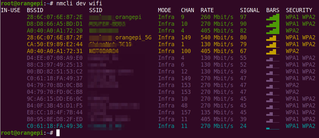
Then use the nmcli command to connect to the scanned WIFI hotspot, where:
wifi_name needs to be replaced with the name of the WIFI hotspot you want to connect to
wifi_passwd needs to be replaced with the password of the WIFI hotspot you want to connect to.
orangepi@orangepi:~$ sudo nmcli dev wifi connect wifi_name password wifi_passwd
Device 'wlan0' successfully activated with 'cf937f88-ca1e-4411-bb50-61f402eef293'.
You can check the IP address of the wifi through the ip addr show wlan0 command
orangepi@orangepi:~$ ip a s wlan0
11: wlan0: <BROADCAST,MULTICAST,UP,LOWER_UP> mtu 1500 qdisc pfifo_fast state UP group default qlen 1000
link/ether 23:8c:d6:ae:76:bb brd ff:ff:ff:ff:ff:ff
inet 192.168.1.11/24 brd 192.168.1.255 scope global dynamic noprefixroute wlan0
valid_lft 259192sec preferred_lft 259192sec
inet6 240e:3b7:3240:c3a0:c401:a445:5002:ccdd/64 scope global dynamic noprefixroute
valid_lft 259192sec preferred_lft 172792sec
inet6 fe80::42f1:6019:a80e:4c31/64 scope link noprefixroute
valid_lft forever preferred_lft forever
Use the ping command to test the connectivity of the wifi network. The ping command can be interrupted by pressing the Ctrl+C shortcut key.
orangepi@orangepi:~$ ping www.orangepi.org -I wlan0
PING www.orangepi.org (182.92.236.130) from 192.168.1.49 wlan0: 56(84) bytes of data.
64 bytes from 182.92.236.130 (182.92.236.130): icmp_seq=1 ttl=52 time=43.5 ms
64 bytes from 182.92.236.130 (182.92.236.130): icmp_seq=2 ttl=52 time=41.3 ms
64 bytes from 182.92.236.130 (182.92.236.130): icmp_seq=3 ttl=52 time=44.9 ms
64 bytes from 182.92.236.130 (182.92.236.130): icmp_seq=4 ttl=52 time=45.6 ms
64 bytes from 182.92.236.130 (182.92.236.130): icmp_seq=5 ttl=52 time=48.8 ms
^C
--- www.orangepi.org ping statistics ---
5 packets transmitted, 5 received, 0% packet loss, time 4006ms
rtt min/avg/max/mdev = 41.321/44.864/48.834/2.484 ms

Server version image connects to WIFI graphically
First log in to the Linux system, there are three ways:
a. If the development board is connected to a network cable, you can remotely log in to the Linux system through ssh.
b. If the development board is connected to the debugging serial port, you can use the serial port terminal to log in to the Linux system (please use MobaXterm for the serial port software, the graphical interface cannot be displayed using minicom)
c. If the development board is connected to an HDMI display, you can log in to the Linux system through the HDMI display terminal.
Then enter the nmtui command in the command line to open the wifi connection interface
orangepi@orangepi:~$ sudo nmtui
Enter the nmtui command to open the interface as shown below
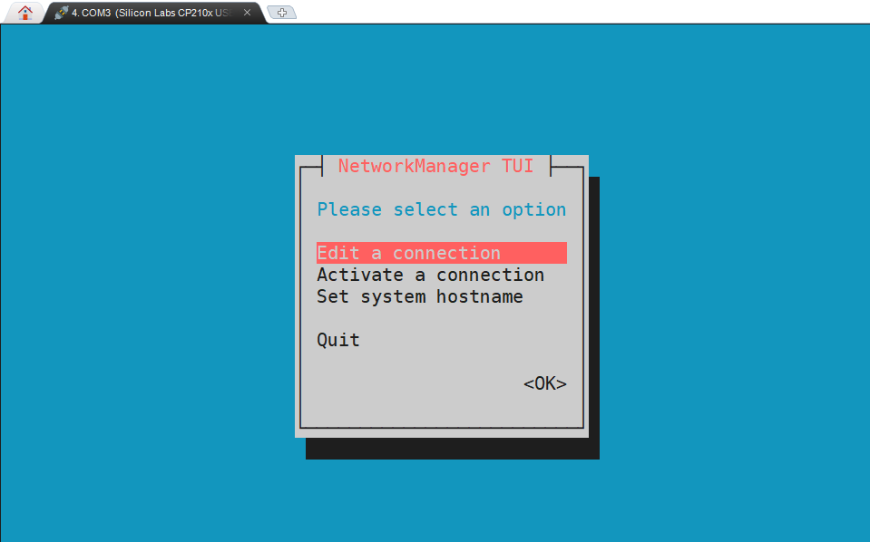
Select Activate a connect and press Enter
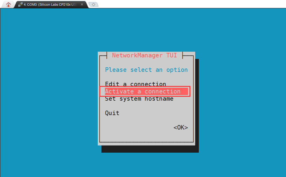
Then you can see all the searched WIFI hotspots
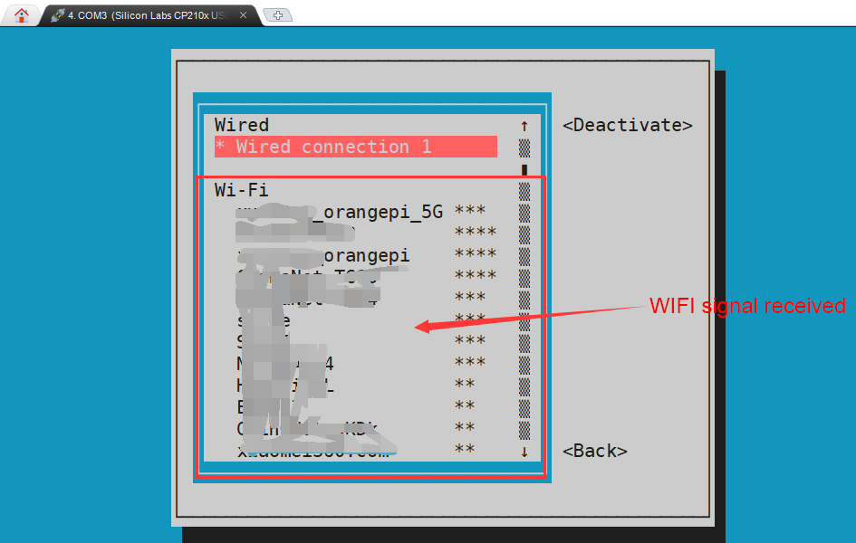
Select the WIFI hotspot you want to connect to, then use the Tab key to position the cursor on Activate and press Enter.
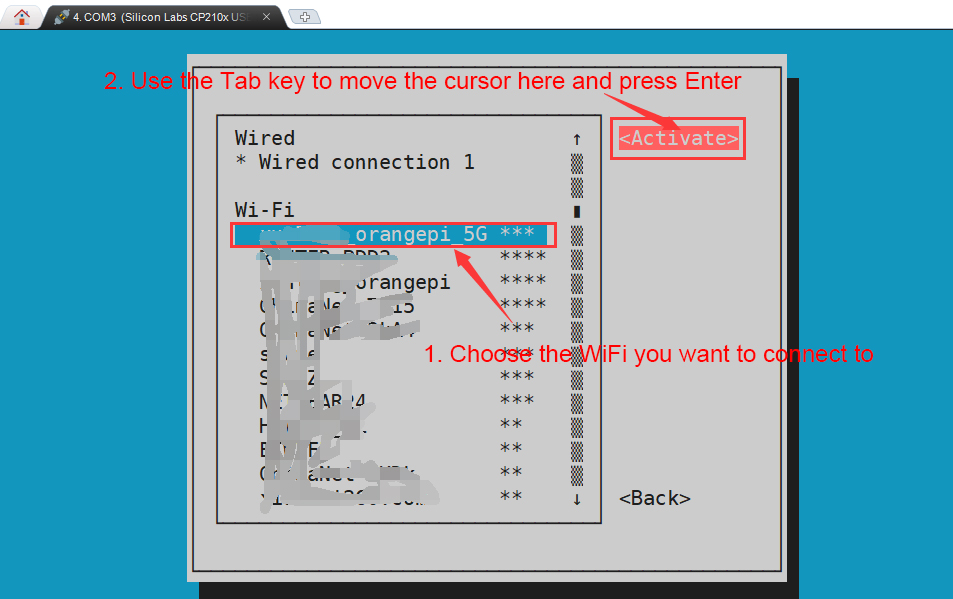
Then a dialog box for entering the password will pop up. Enter the corresponding password in Password and press Enter to start connecting to WIFI.
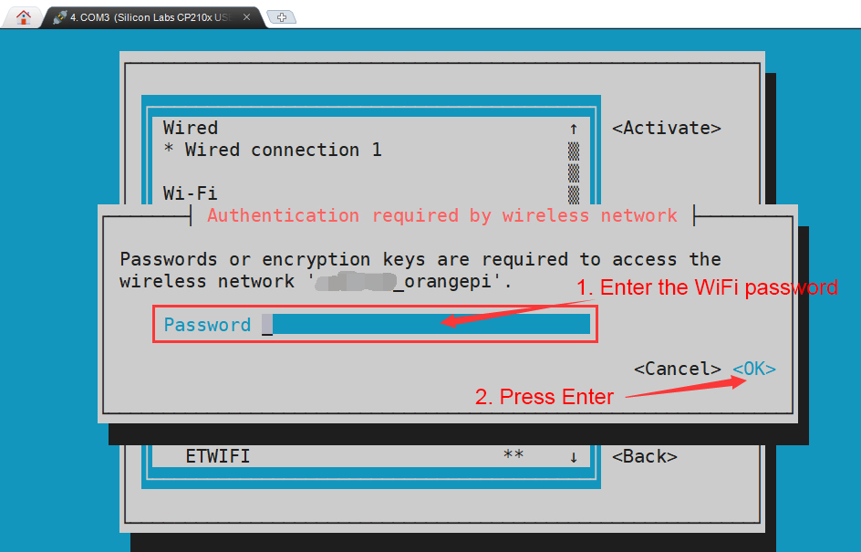
After the WIFI connection is successful, a "*" will be displayed in front of the connected WIFI name.
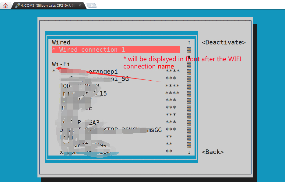
You can check the IP address of the wifi through the ip a s wlan0 command
orangepi@orangepi:~$ ip a s wlan0
11: wlan0: <BROADCAST,MULTICAST,UP,LOWER_UP> mtu 1500 qdisc pfifo_fast state UP group default qlen 1000
link/ether 24:8c:d3:aa:76:bb brd ff:ff:ff:ff:ff:ff
inet 192.168.1.11/24 brd 192.168.1.255 scope global dynamic noprefixroute wlan0
valid_lft 259069sec preferred_lft 259069sec
inet6 240e:3b7:3240:c4a0:c401:a445:5002:ccdd/64 scope global dynamic noprefixroute
valid_lft 259071sec preferred_lft 172671sec
inet6 fe80::42f1:6019:a80e:4c31/64 scope link noprefixroute
valid_lft forever preferred_lft forever
Use the ping command to test the connectivity of the wifi network. The ping command can be interrupted by pressing the Ctrl+C shortcut key.
orangepi@orangepi:~$ ping www.orangepi.org -I wlan0
PING www.orangepi.org (182.92.236.130) from 192.168.1.49 wlan0: 56(84) bytes of data.
64 bytes from 182.92.236.130 (182.92.236.130): icmp_seq=1 ttl=52 time=43.5 ms
64 bytes from 182.92.236.130 (182.92.236.130): icmp_seq=2 ttl=52 time=41.3 ms
64 bytes from 182.92.236.130 (182.92.236.130): icmp_seq=3 ttl=52 time=44.9 ms
64 bytes from 182.92.236.130 (182.92.236.130): icmp_seq=4 ttl=52 time=45.6 ms
64 bytes from 182.92.236.130 (182.92.236.130): icmp_seq=5 ttl=52 time=48.8 ms
^C
--- www.orangepi.org ping statistics ---
5 packets transmitted, 5 received, 0% packet loss, time 4006ms
rtt min/avg/max/mdev = 41.321/44.864/48.834/2.484 ms


Test method for desktop image
Click the network configuration icon in the upper right corner of the desktop (please do not connect the network cable when testing WIFI)
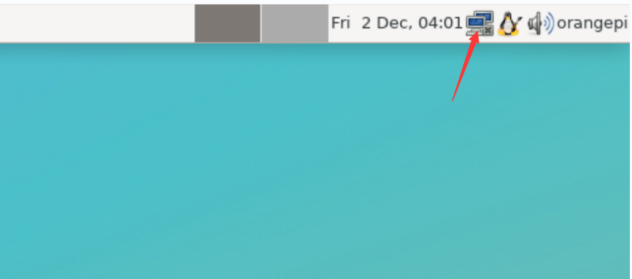
Click More networks in the pop-up drop-down box to see all scanned WIFI hotspots, and then select the WIFI hotspot you want to connect to.

Then enter the password of the WIFI hotspot and click Connect to start connecting to WIFI
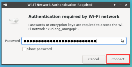
After connecting to WIFI, you can open the browser to check whether you can access the Internet. The browser entrance is as shown below
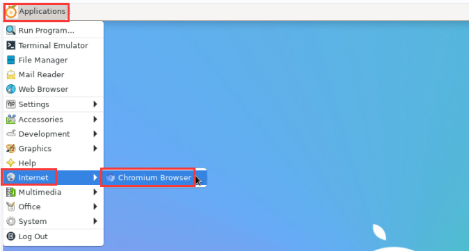
If you can open other web pages after opening the browser, it means the WIFI connection is normal.


Method to create WIFI hotspot through create_ap
|
create_ap is a script that helps quickly create WIFI hotspots on Linux, and supports bridge and NAT modes. It can automatically combine hostapd, dnsmasq and iptables to complete the setting of WIFI hotspots, avoiding users from complicated configurations. The github address is as follows: |
|
The Linux image released by OPi has been pre-installed with the create_ap script. You can use the create_ap command to create a WIFI hotspot. The basic command format of create_ap is as follows:
* wifi-interface: The name of the wireless network card * interface-with-internet: The name of the network card that can connect to the Internet, usually eth0 * access-point-name: Hotspot name * passphrase: hotspot password |
create_ap method to create WIFI hotspot in NAT mode
Enter the following command to create a WIFI hotspot with the name orangepi and password orangepi in NAT mode
Note that in the following command, Debian12 needs to modify eth0 to end0
orangepi@orangepi:~$ sudo create_ap -m nat wlan0 eth0 orangepi orangepi --no-virt
If the following information is output, it means that the WIFI hotspot is successfully created.
orangepi@orangepi:~$ sudo create_ap -m nat wlan0 eth0 orangepi orangepi --no-virt
Config dir: /tmp/create_ap.wlan0.conf.TQkJtsz1
PID: 26139
Network Manager found, set wlan0 as unmanaged device... DONE
Sharing Internet using method: nat
hostapd command-line interface: hostapd_cli -p /tmp/create_ap.wlan0.conf.TQkJtsz1/hostapd_ctrl
wlan0: interface state UNINITIALIZED->ENABLED
wlan0: AP-ENABLED
wlan0: STA ce:bd:9a:dd:a5:86 IEEE 802.11: associated
wlan0: AP-STA-CONNECTED ce:bd:9a:dd:a5:86
wlan0: STA ce:bd:9a:dd:a5:86 RADIUS: starting accounting session D4FBF7E5C604F169
wlan0: STA ce:bd:9a:dd:a5:86 WPA: pairwise key handshake completed (RSN)
wlan0: EAPOL-4WAY-HS-COMPLETED ce:bd:9a:dd:a5:86
At this time, take out your mobile phone and find the WIFI hotspot named orangepi created by the development board in the searched WIFI list. Then you can click orangepi to connect to the hotspot. The password is orangepi set above.
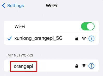
The display after successful connection is as shown below
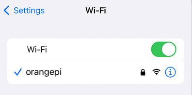
In NAT mode, the wireless device connected to the development board's hotspot requests an IP address from the development board's DHCP service, so there will be two different network segments. For example, the development board's IP here is 192.168.1.X
Note that in the following command, Debian12 needs to modify eth0 to end0.
orangepi@orangepi:~$ sudo ifconfig eth0
eth0: flags=4163<UP,BROADCAST,RUNNING,MULTICAST> mtu 1500
inet 192.168.1.150 netmask 255.255.255.0 broadcast 192.168.1.255
inet6 fe80::938f:8776:5783:afa2 prefixlen 64 scopeid 0x20<link>
ether 4a:a0:c8:25:42:82 txqueuelen 1000 (Ethernet)
RX packets 25370 bytes 2709590 (2.7 MB)
RX errors 0 dropped 50 overruns 0 frame 0
TX packets 3798 bytes 1519493 (1.5 MB)
TX errors 0 dropped 0 overruns 0 carrier 0 collisions 0
device interrupt 83
The DHCP service of the development board will assign the IP address of 192.168.12.0/24 to the device connected to the hotspot by default. At this time, click on the connected WIFI hotspot orangepi, and then you can see that the IP address of the mobile phone is 192.168.12.X.
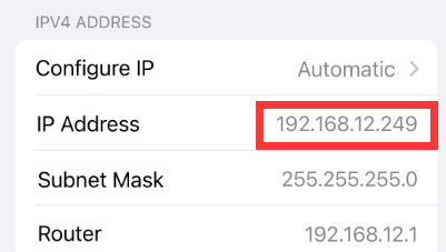
If you want to specify a different network segment for the connected device, you can specify it through the -g parameter. For example, use the -g parameter to specify the network segment of the access point AP as 192.168.2.1.
Note that in the following command, Debian12 needs to modify eth0 to end0.
orangepi@orangepi:~$ sudo create_ap -m nat wlan0 eth0 orangepi orangepi -g 192.168.2.1 --no-virt
At this time, after connecting to the hotspot through the mobile phone, click on the connected WIFI hotspot orangepi, and then you can see that the IP address of the mobile phone is 192.168.2.X


Without specifying the --freq-band parameter, the hotspot created by default is in the 2.4G frequency band. If you want to create a hotspot in the 5G frequency band, you can specify it through the --freq-band 5 parameter. The specific command is as follows
Note that in the following command, Debian12 needs to modify eth0 to end0
orangepi@orangepi:~$ sudo create_ap -m nat wlan0 eth0 orangepi orangepi --freq-band 5 --no-virt
If you need to hide the SSID, you can specify the --hidden parameter. The specific command is as follows
Note that in the following command, Debian12 needs to modify eth0 to end0.
orangepi@orangepi:~$ sudo create_ap -m nat wlan0 eth0 orangepi orangepi --hidden --no-virt
At this time, the mobile phone cannot search for WIFI hotspots. You need to manually specify the WIFI hotspot name and enter the password to connect to the WIFI hotspot.
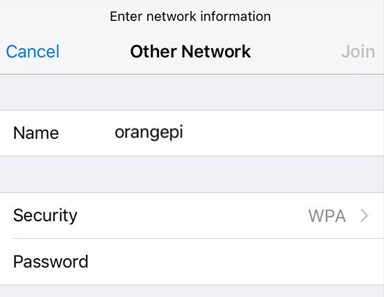

create_ap method to create WIFI hotspot in bridge mode
Enter the following command to create a WIFI hotspot with the name orangepi and password orangepi in bridge mode
Note that in the following command, Debian12 needs to modify eth0 to end0.
orangepi@orangepi:~$ sudo create_ap -m bridge wlan0 eth0 orangepi orangepi --no-virt
If the following information is output, it means that the WIFI hotspot is successfully created.
orangepi@orangepi:~$ sudo create_ap -m bridge wlan0 eth0 orangepi orangepi --no-virt
Config dir: /tmp/create_ap.wlan0.conf.zAcFlYTx
PID: 27707
Network Manager found, set wlan0 as unmanaged device... DONE
Sharing Internet using method: bridge
Create a bridge interface... br0 created.
hostapd command-line interface: hostapd_cli -p /tmp/create_ap.wlan0.conf.zAcFlYTx/hostapd_ctrl
wlan0: interface state UNINITIALIZED->ENABLED
wlan0: AP-ENABLED
wlan0: STA ce:bd:9a:dd:a5:86 IEEE 802.11: associated
wlan0: AP-STA-CONNECTED ce:bd:9a:dd:a5:86
wlan0: STA ce:bd:9a:dd:a5:86 RADIUS: starting accounting session 937BF40E51897A7B
wlan0: STA ce:bd:9a:dd:a5:86 WPA: pairwise key handshake completed (RSN)
wlan0: EAPOL-4WAY-HS-COMPLETED ce:bd:9a:dd:a5:86
At this time, take out your mobile phone and find the WIFI hotspot named orangepi created by the development board in the searched WIFI list. Then you can click orangepi to connect to the hotspot. The password is orangepi set above.
The display after successful connection is as shown below
In bridge mode, the wireless device connected to the hotspot of the development board also requests an IP address from the DHCP service of the main router (the router to which the development board is connected). For example, the IP of the development board here is 192.168.1.X
orangepi@orangepi:~$ sudo ifconfig eth0
eth0: flags=4163<UP,BROADCAST,RUNNING,MULTICAST> mtu 1500
inet 192.168.1.150 netmask 255.255.255.0 broadcast 192.168.1.255
inet6 fe80::938f:8776:5783:afa2 prefixlen 64 scopeid 0x20<link>
ether 4a:a0:c8:25:42:82 txqueuelen 1000 (Ethernet)
RX packets 25370 bytes 2709590 (2.7 MB)
RX errors 0 dropped 50 overruns 0 frame 0
TX packets 3798 bytes 1519493 (1.5 MB)
TX errors 0 dropped 0 overruns 0 carrier 0 collisions 0
device interrupt 83
The IP of the device connected to the WIFI hotspot is also assigned by the main router, so the mobile phone connected to the WIFI hotspot and the development board are in the same network segment. At this time, click on the connected WIFI hotspot orangepi, and then you can see the IP address of the mobile phone. Also 192.168.1.X.
Without specifying the --freq-band parameter, the hotspot created by default is in the 2.4G frequency band. If you want to create a hotspot in the 5G frequency band, you can specify it through the --freq-band parameter. The specific command is as follows
Note that in the following command, Debian12 needs to modify eth0 to end0.
orangepi@orangepi:~$ sudo create_ap -m bridge wlan0 eth0 orangepi orangepi --freq-band 5 --no-virt
If you need to hide the SSID, you can specify the --hidden parameter. The specific command is as follows
Note that in the following command, Debian12 needs to modify eth0 to end0.
orangepi@orangepi:~$ sudo create_ap -m bridge wlan0 eth0 orangepi orangepi --hidden --no-virt
At this time, the mobile phone cannot search for WIFI hotspots. You need to manually specify the WIFI hotspot name and enter the password to connect to the WIFI hotspot.
How to set a static IP address
|
Please do not set a static IP address by modifying the /etc/network/interfaces configuration file. |
Use the nmtui command to set a static IP address
First run the nmtui command
orangepi@orangepi:~$ sudo nmtui
Then select Edit a connection and press the Enter key
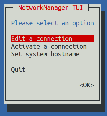
Then select the network interface for which a static IP address needs to be set. For example, to set the static IP address of the Ethernet interface, select Wired connection 1.
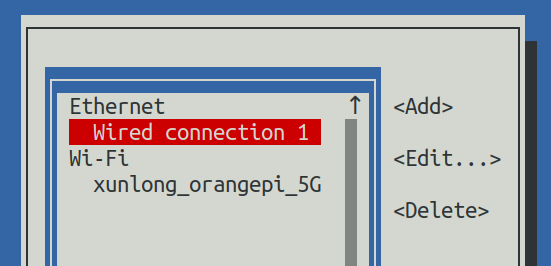
Then select Edit via the Tab key and press the Enter key
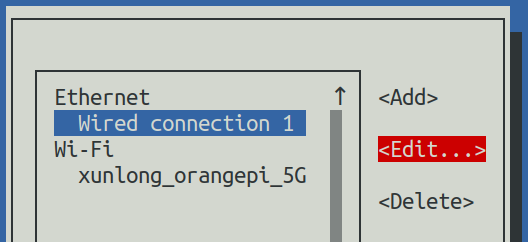
Then use the Tab key to move the cursor to the <Automatic> position shown in the figure below to configure IPv4
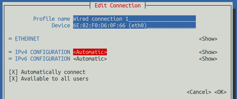
Then press Enter, select Manual through the up and down arrow keys, and then press Enter to confirm.
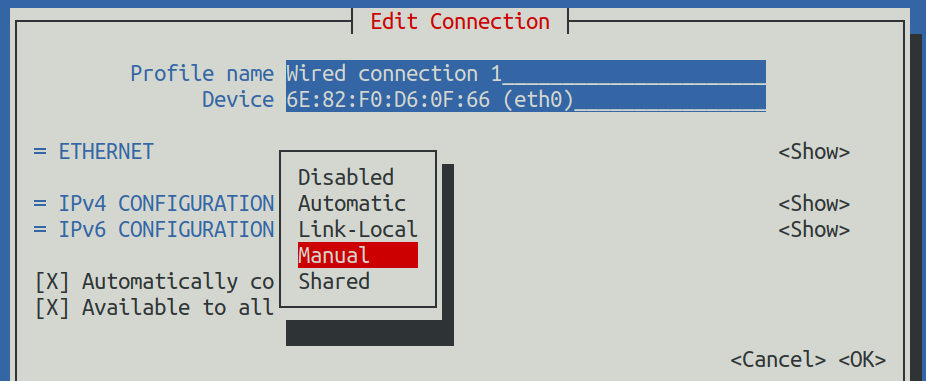
The display after selection is as shown below

Then move the cursor to <Show> via the Tab key
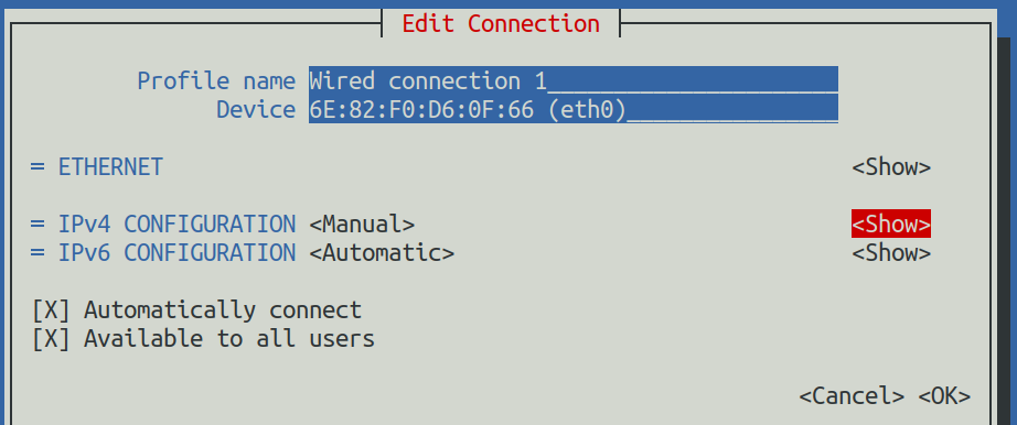
Then press Enter. After pressing Enter, the following setting interface will pop up.
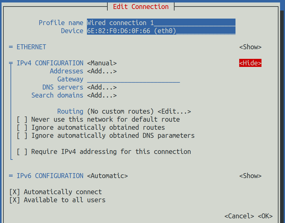
Then you can set the IP address (Addresses), gateway (Gateway) and DNS server address as shown in the figure below (there are many other setting options, please explore by yourself), please set according to your specific needs. The values set in the image below are just an example
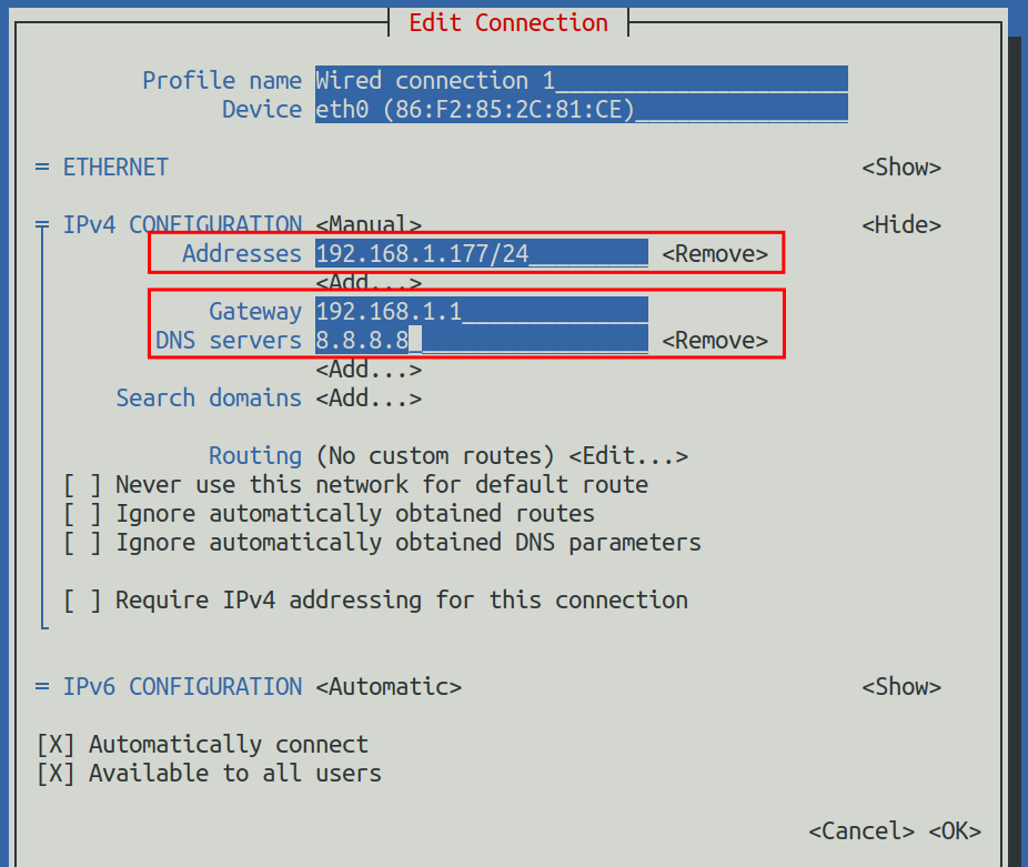
After setting, move the cursor to <OK> in the lower right corner, and then press Enter to confirm.
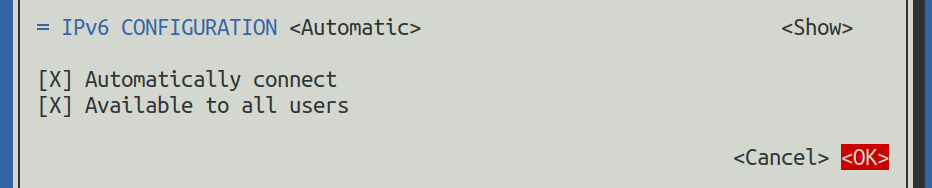
Then click <Back> to return to the previous level selection interface

Then select Activate a connection, then move the cursor to <OK>, and finally click Enter
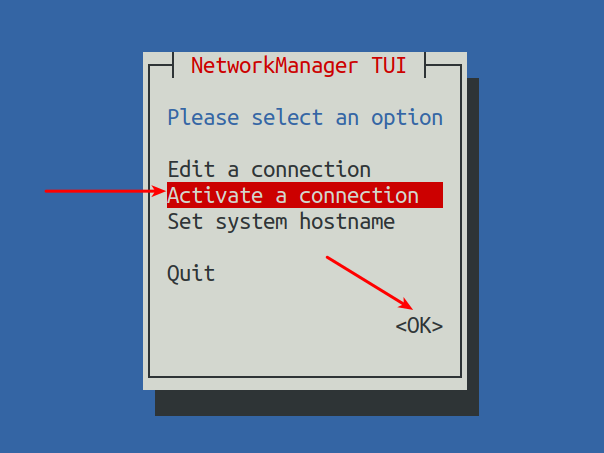
Then select the network interface that needs to be set, such as Wired connection 1, then move the cursor to <Deactivate>, and then press the Enter key to disable Wired connection 1
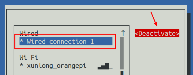
Then please do not move the cursor, and then press the Enter key to re-enable Wired connection 1, so that the static IP address set previously will take effect.
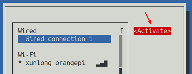
Then you can exit nmtui through the <Back> and Quit buttons
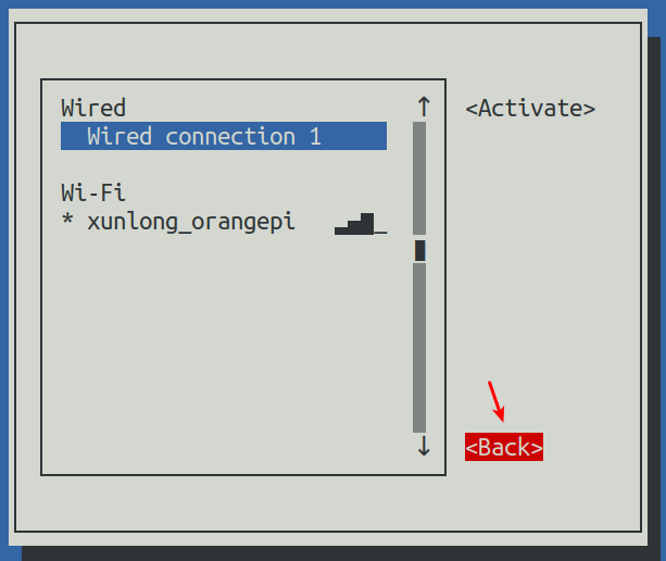
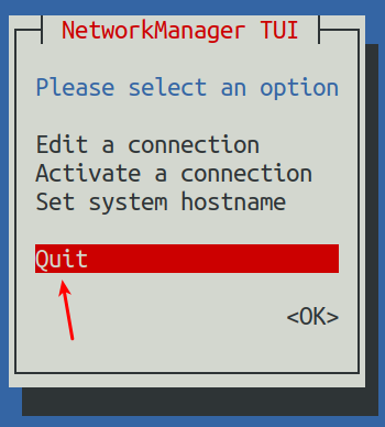
Then through ip a s eth0 you can see that the IP address of the network port has become the static IP address set previously.
Note that in the following command, Debian12 needs to modify eth0 to end0.
orangepi@orangepi:~$ ip a s eth0
3: eth0: <BROADCAST,MULTICAST,UP,LOWER_UP> mtu 1500 qdisc pfifo_fast state UP group default qlen 1000
link/ether 5e:ac:14:a5:92:b3 brd ff:ff:ff:ff:ff:ff
inet 192.168.1.177/24 brd 192.168.1.255 scope global noprefixroute eth0
valid_lft forever preferred_lft forever
inet6 241e:3b8:3240:c3a0:e269:8305:dc08:135e/64 scope global dynamic noprefixroute
valid_lft 259149sec preferred_lft 172749sec
inet6 fe80::957d:bbbe:4928:3604/64 scope link noprefixroute
valid_lft forever preferred_lft forever
Then you can test the network connectivity to check whether the IP address is configured OK. The ping command can be interrupted by using the Ctrl+C shortcut key.
Note that in the following command, Debian12 needs to modify eth0 to end0.
orangepi@orangepi:~$ ping 192.168.1.177 -I eth0
PING 192.168.1.47 (192.168.1.47) from 192.168.1.188 eth0: 56(84) bytes of data.
64 bytes from 192.168.1.47: icmp_seq=1 ttl=64 time=0.233 ms
64 bytes from 192.168.1.47: icmp_seq=2 ttl=64 time=0.263 ms
64 bytes from 192.168.1.47: icmp_seq=3 ttl=64 time=0.273 ms
64 bytes from 192.168.1.47: icmp_seq=4 ttl=64 time=0.269 ms
64 bytes from 192.168.1.47: icmp_seq=5 ttl=64 time=0.275 ms
^C
--- 192.168.1.47 ping statistics ---
5 packets transmitted, 5 received, 0% packet loss, time 4042ms
rtt min/avg/max/mdev = 0.233/0.262/0.275/0.015 ms


Use nmcli command to set static IP address
If you want to set a static IP address for the network port, please plug the network cable into the development board first. If you need to set a static IP address for WIFI, please connect to WIFI first, and then start setting the static IP address.
Then you can view the name of the network device through the nmcli con show command, as shown below
orangepi is the name of the WIFI network interface (the names are not necessarily the same)
Wired connection 1 is the name of the Ethernet interface
orangepi@orangepi:~$ nmcli con show
NAMEUUID TYPE DEVICE
orangepicfc4f922-ae48-46f1-84e1-2f19e9ec5e2awifi wlan0
Wired connection 19db058b7-7701-37b8-9411-efc2ae8bfa30ethernet eth0
中Then enter the following command, where
"Wired connection 1" means setting the static IP address of the Ethernet port. If you need to set the static IP address of WIFI, please change it to the name corresponding to the WIFI network interface (can be obtained through the nmcli con show command)
ipv4.addresses is followed by the static IP address to be set, which can be modified to the value you want to set.
ipv4.gateway represents the address of the gateway
orangepi@orangepi:~$ sudo nmcli con mod "Wired connection 1" \
ipv4.addresses "192.168.1.110" \ipv4.gateway "192.168.1.1" \
ipv4.dns "8.8.8.8" \
ipv4.method "manual"
Then restart the linux system
orangepi@orangepi:~$ sudo reboot
Then re-enter the Linux system and use the ip addr show eth0 command to see that the IP address has been set to the desired value.
orangepi@orangepi:~$ ip addr show eth0
3: eth0: <BROADCAST,MULTICAST,UP,LOWER_UP> mtu 1500 qdisc pfifo_fast state UP group default qlen 1000
link/ether 5e:ae:14:a5:91:b3 brd ff:ff:ff:ff:ff:ff
inet 192.168.1.110/32 brd 192.168.1.110 scope global noprefixroute eth0
valid_lft forever preferred_lft forever
inet6 240e:3b7:3240:c3a0:97de:1d01:b290:fe3a/64 scope global dynamic noprefixroute
valid_lft 259183sec preferred_lft 172783sec
inet6 fe80::3312:861a:a589:d3c/64 scope link noprefixroute
valid_lft forever preferred_lft forever
How to set up the Linux system to automatically connect to the network for the first time
|
The development board has an Ethernet port. If you want to remotely log in to the Linux system of the development board through the Ethernet port, you only need to plug in a network cable that can access the Internet normally. After starting the Linux system, it will automatically connect to the Ethernet port through DHCP. Assign an IP address, and then we can obtain the IP address of the Ethernet port through the HDMI screen, serial port, or view the router's background, and then log in to the Linux system remotely. The development board also has wireless WIFI. If you want to remotely log in to the Linux system of the development board through WIFI, you need to remotely log in to the Linux system through ssh through the IP address of the Ethernet port and then use commands to connect to WIFI, or use commands on the HDMI screen or serial port. Connect to WIFI. But if there is no HDMI screen and serial port module, although there is a network cable, the IP address of the development board cannot be viewed through the router background. Or if there is no HDMI screen, serial port module and network cable, and only WIFI can be connected, you can use the method introduced in this section to automatically connect to WIFI and set the static IP address of WIFI or automatically set the static IP address of the Ethernet port. |
|
To use the method in this section, you first need to prepare a Linux system machine. For example, a computer or virtual machine with Ubuntu system installed. Why do you need a Linux system machine? Because the root file system of the Linux system of the development board burned in the TF card is in ext4 format. The Linux system machine can mount it normally and then modify the configuration file in it. |
|
If you want to modify it in a Windows system, you can use the software Paragon ExtFS for Windows. Since this software requires payment, and there is currently no similar free software that is easy to use, I will not demonstrate it in detail here. In addition, if you have any problems when trying to use Paragon ExtFS for Windows, please solve it yourself. We will not answer questions. |
First burn the Linux image of the development board you want to use into a TF card, and then use a card reader to insert the TF card with the Linux image of the development board into a machine with a Linux system (such as a machine with Ubuntu system Computer, the following uses Ubuntu computer as an example for demonstration)
When the TF card is inserted into the Ubuntu computer, the Ubuntu computer will generally automatically mount the Linux root file system partition in the TF card. From the following command, we can know that /media/test/opi_root is the Linux root file in the TF card. System mounting path
test@test:~$ df -h | grep "media"
/dev/sdd1 1.4G 1.2G 167M 88% /media/test/opi_root
test@test:~$ ls /media/test/opi_root
bin boot dev etc home lib lost+found media mnt opt proc root run
sbin selinux srv sys tmp usr varThen enter the /boot directory of the Linux system burned in the TF card
test@test:~$ cd /media/test/opi_root/boot/
Then copy the orangepi_first_run.txt.template to orangepi_first_run.txt. Through the orangepi_first_run.txt configuration file, you can set the development board to automatically connect to a WIFI hotspot when the Linux system starts for the first time. You can also set the WIFI or Ethernet port Static IP address.
test@test:/media/test/opi_root/boot$ sudo cp orangepi_first_run.txt.template orangepi_first_run.txt
You can open the orangepi_first_run.txt file through the following command, and then you can view and modify the contents.
test@test:/media/test/opi_root/boot$ sudo vim orangepi_first_run.txt
Variable usage instructions in the orangepi_first_run.txt file
FR_general_delete_this_file_after_completion The variable is used to set whether to delete the orangepi_first_run.txt file after the first startup. The default is 1, which means deletion. If set to 0, orangepi_first_run.txt will be renamed after the first startup.orangepi_first_run.txt.old, Generally, just keep the default value
FR_net_change_defaults The variable is used to set whether to change the default network settings. This must be set to 1, otherwise all network settings will not take effect.
FR_net_ethernet_enabled The variable is used to control whether to enable the configuration of the Ethernet port. If you need to set the static IP address of the Ethernet port, please set it to 1
FR_net_wifi_enabled The variable is used to control whether to enable WIFI configuration. If you need to set the development board to automatically connect to WIFI hotspots, you must set it to 1. Also please note that if this variable is set to 1, the Ethernet port settings will be invalid. That is to say, the WIFI and Ethernet ports cannot be set at the same time (why, because it is not necessary...)
FR_net_wifi_ssid Variable is used to set the name of the WIFI hotspot you want to connect to
FR_net_wifi_key Variable is used to set the password of the WIFI hotspot you want to connect to
FR_net_use_static Variables are used to set whether the static IP address of the WIFI or Ethernet port needs to be set.
FR_net_static_ip The variable is used to set the static IP address. Please set it according to your actual situation.
FR_net_static_gateway Variables are used to set the gateway. Please set according to your actual situation.
Here are some specific setting examples:
For example, if you want the Linux system of the development board to automatically connect to the WIFI hotspot after it is started for the first time, you can set it like this:
a) Set FR_net_change_defaults to 1
b) Set FR_net_wifi_enabled to 1
c) Set FR_net_wifi_ssid to the name of the WIFI hotspot you want to connect to
d) Set FR_net_wifi_key to the password of the WIFI hotspot you want to connect to
For example, you want the Linux system of the development board to automatically connect to the WIFI hotspot after the first startup, and set the WIFI IP address to a specific static IP address (so that when the Linux system starts, you can directly use the set static IP address to ssh remotely Log in to the development board, there is no need to check the IP address of the development board through the router background), you can set it like this:
a) Set FR_net_change_defaults to 1
b) Set FR_net_wifi_enabled to 1
c) Set FR_net_wifi_ssid to the name of the WIFI hotspot you want to connect to
d) Set FR_net_wifi_key to the password of the WIFI hotspot you want to connect to
e) Set FR_net_use_static to 1
f) Set FR_net_static_ip to the desired IP address
g) Set R_net_static_gateway to the corresponding gateway address
For example, if you want the development board's Linux system to automatically set the IP address of the Ethernet port to the desired static IP address after it is started for the first time, you can set it like this
a) Set FR_net_change_default to 1
b) Set FR_net_ethernet_enabled to 1
c) Set FR_net_use_static to 1
d) Set FR_net_static_ip to the desired IP address
e) Set FR_net_static_gateway to the corresponding gateway address
After modifying the orangepi_first_run.txt file, you can exit the /boot directory of the development board Linux system in the TF card, uninstall the TF card, and then insert the TF card into the development board to start.
If a static IP address is not set, you still need to check the IP address through the router background. If a static IP address is set, you can ping the set static IP address on the computer. If you can ping, it means that the system has started normally, and The network has been set up correctly, and then you can use the set IP address to ssh to remotely log in to the Linux system of the development board.
After the development board's Linux system is started for the first time, orangepi_first_run.txt will be deleted or renamed to orangepi_first_run.txt.old. At this time, even if the orangepi_first_run.txt configuration file is reset, and then the development board's Linux system is restarted, orangepi_first_run. The configuration in txt will not take effect again, because this configuration will only take effect when the Linux system is started for the first time after burning it. Please pay special attention to this point.
SSH remote login development board
|
Linux systems enable ssh remote login by default and allow root users to log in to the system. Before ssh login, you first need to ensure that the Ethernet or wifi network is connected, and then use the ip addr command or obtain the IP address of the development board by checking the router |
SSH remote login development board under Ubuntu
- Obtain the IP address of the development board
- Then you can remotely log in to the Linux system through the ssh command
test@test:~$ ssh orangepi@192.168.1.xxx (Need to be replaced with the IP address of the development board)
orangepi@192.168.1.xx's password: (Enter your password here, the default password is orangepi)
Note that when entering a password, the specific content of the entered password will not be displayed on the screen. Please do not think that there is something wrong. Just press Enter after entering it.
If you are prompted to refuse the connection, as long as you are using the image provided by Orange Pi, please do not doubt whether the orangepi password is incorrect, but look for other reasons.
After successfully logging into the system, the display is as shown below
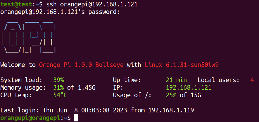
If ssh cannot log in to the Linux system normally, first check whether the IP address of the development board can be pinged. If there is no problem with pinging, you can log in to the Linux system through the serial port or HDMI display and enter the following command on the development board before trying again. Can it be connected?:
root@orangepi:~# reset_ssh.sh
If it still doesn't work, please try restarting the system.

SSH remote login development board under Windows
First obtain the IP address of the development board
You can use MobaXterm to remotely log in to the development board under Windows. First create a new ssh session.
Open Session
Then select SSH in Session Setting
Then enter the IP address of the development board in Remote host
Then enter the username root or orangepi of the linux system in Specify username.
Finally click OK
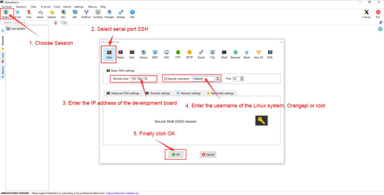
You will then be prompted to enter a password. The default passwords for both root and orangepi users are orangepi.
Note that when entering a password, the specific content of the entered password will not be displayed on the screen. Please do not think that there is any malfunction. Just press Enter after entering the password.
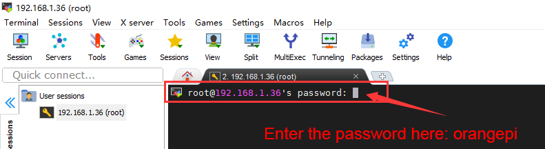
After successfully logging into the system, the display is as shown below
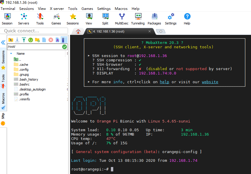


HDMI test
HDMI display test
Use Mini HDMI to HDMI cable to connect the Orange Pi development board and HDMI display
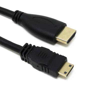
After starting the Linux system, if there is image output on the HDMI display, it means that the HDMI interface is working normally.
Note that although many laptops have HDMI interfaces, the HDMI interface of the laptop generally only has the output function and does not have the HDMI in function, which means that the HDMI output of other devices cannot be displayed on the laptop screen
When you want to connect the HDMI of the development board to the HDMI interface of your laptop, please first confirm that your laptop supports the HDMI in function
When HDMI does not display, please first check whether the HDMI cable is plugged in tightly. After confirming that the wiring is OK, you can try a different screen to see if there is any display.
HDMI to VGA display test
First you need to prepare the following accessories
HDMI to VGA converter
A VGA cable and a Mini HDMI male to HDMI female adapter
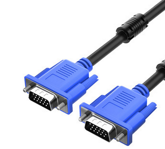
A monitor or TV that supports VGA interface
HDMI to VGA display test is as follows
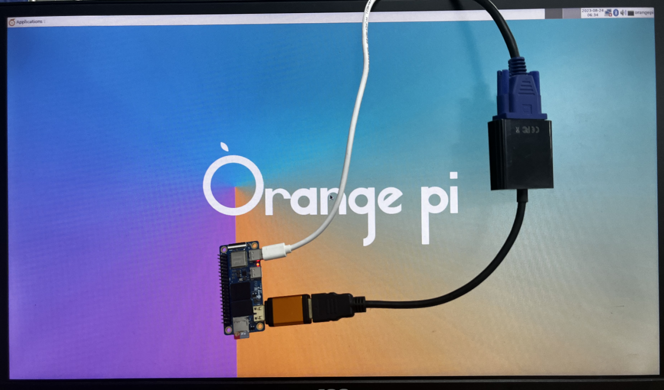
When using HDMI to VGA display, the development board and the Linux system of the development board do not need to make any settings. You only need the Mini HDMI interface of the development board to display normally. So if there is a problem with the test, please check whether there is a problem with the HDMI to VGA converter, VGA cable and monitor.


How to set HDMI resolution in Linux5.4 system
|
Note: This method is only applicable to systems with Linux 5.4 kernel. |
There is a disp_mode variable in /boot/orangepiEnv.txt of the Linux system, which can be used to set the resolution of HDMI output. The default resolution of the Linux system is 1080p60
orangepi@orangepi:~$ sudo vim /boot/orangepiEnv.txt
verbosity=1
console=both
disp_mode=1080p60
fb0_width=1920
fb0_height=1080
The disp_mode variable supports setting values as shown in the table below
| disp_mode supported values | HDMI resolution | HDMI refresh rate |
| 480i | 720x480 | 60 |
| 576i | 720x480 | 50 |
| 480p | 720x480 | 60 |
| 576p | 720x576 | 60 |
| 720p50 | 1280x720 | 50 |
| 720p60 | 1280x720 | 60 |
| 1080i50 | 1920x1080 | 50 |
| 1080i60 | 1920x1080 | 60 |
| 1080p24 | 1920x1080 | 24 |
| 1080p50 | 1920x1080 | 50 |
| 1080p60 | 1920x1080 | 60 |
|
Note: Linux systems currently do not support 4K resolution. |
Change the value of the disp_mode variable to the resolution you want to output, then restart the system, and HDMI will output the set resolution.
The method of checking the HDMI output resolution is as follows. If the displayed resolution is the same as the set resolution, it means that the settings on the development board are correct.
orangepi@orangepi:~$ sudo cat /sys/class/disp/disp/attr/sys
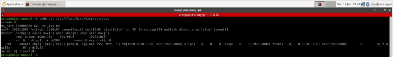

How to modify the width and height of Framebuffer in Linux5.4 system
|
Note: This method is only applicable to systems with Linux 5.4 kernel. |
There are two variables, fb0_width and fb0_height, in /boot/orangepiEnv.txt of the Linux system. You can use them to set the width and height of the Framebuffer. The Linux system defaults to fb0_width=1920 and fb0_height=1080.
|
orangepi@orangepi:~$ sudo vim /boot/orangepiEnv.txt verbosity=1 console=both disp_mode=1080p60 fb0_width=1920 fb0_height=1080 |
The reference values corresponding to different resolutions of fb0_width and fb0_height are as follows::
| HDMI resolution | fb0_width | fb0_height |
| 480p | 720 | 480 |
| 576p | 720 | 576 |
| 720p | 1280 | 720 |
| 1080p | 1920 | 1080 |
Under the same HDMI resolution, when the values set by fb0_width and fb0_height are larger, the text displayed on the screen will be smaller. When the values of fb0_width and fb0_height are set smaller, the text displayed on the screen will be larger.
Framebuffer cursor setting
The softcursor used by Framebuffer, the method to set the cursor to blink or not to blink is as follows
root@orangepi:~# echo 1 > /sys/class/graphics/fbcon/cursor_blink #Cursor flashes
root@orangepi:~# echo 0 > /sys/class/graphics/fbcon/cursor_blink #Cursor does not flash
If you need to hide the cursor, you can add vt.global_cursor_default=0 to the extraargs variable in /boot/orangepiEnv.txt (the value of extraargs will be assigned to the bootargs environment variable and eventually passed to the kernel) (if vt.global_cursor_default=1, it will be displayed cursor), then restart the system and you will see that the cursor has disappeared.
orangepi@orangepi:~$ sudo vim /boot/orangepiEnv.txt
verbosity=1
console=both
disp_mode=1080p60
fb0_width=1920
fb0_height=1080
extraargs=vt.global_cursor_default=0
How to use Bluetooth
Testing method for desktop image
Click the Bluetooth icon in the upper right corner of the desktop
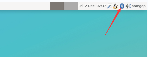
Then select the adapter
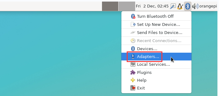
If prompted with the following interface, please select Yes.
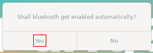
Then set the Visibility Setting to Always visible in the Bluetooth adapter setting interface, and then turn it off.
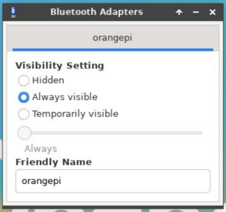
Then open the configuration interface of the Bluetooth device
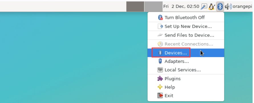
Click Search to start scanning for surrounding Bluetooth devices
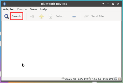
Then select the Bluetooth device you want to connect, and then right-click the mouse to pop up the operation interface for the Bluetooth device. Select Pair to start pairing. The demonstration here is pairing with an Android phone.
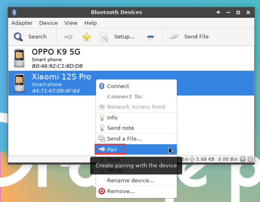
When pairing, a pairing confirmation box will pop up in the upper right corner of the desktop. Just select Confirm to confirm. At this time, you also need to confirm on the mobile phone.
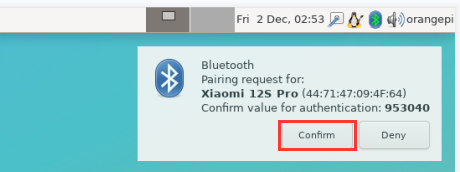
After pairing with the mobile phone, you can select the paired Bluetooth device, then right-click and select Send a File to start sending a picture to the mobile phone.
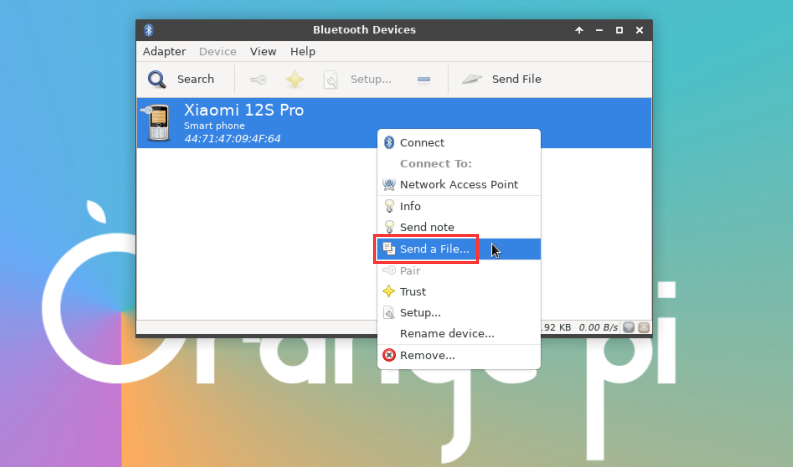
The interface for sending pictures is as follows
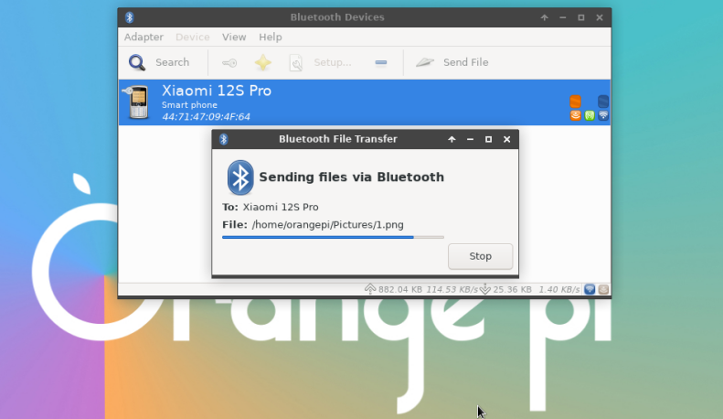


How to use server version image
After entering the system, you can first check whether there is a Bluetooth device node through the hciconfig command. If it exists, it means that the Bluetooth initialization is normal.
orangepi@orangepi:~$ sudo apt update && sudo apt install -y bluez
orangepi@orangepi:~$ hciconfig -a
hci0: Type: Primary Bus: UART
BD Address: 3E:61:3D:19:0E:52 ACL MTU: 1021:8 SCO MTU: 240:3
UP RUNNING
RX bytes:925 acl:0 sco:0 events:72 errors:0
TX bytes:5498 acl:0 sco:0 commands:72 errors:0
Features: 0xbf 0xff 0x8d 0xfe 0xdb 0x3d 0x7b 0xc7
Packet type: DM1 DM3 DM5 DH1 DH3 DH5 HV1 HV2 HV3
Link policy: RSWITCH SNIFF
Link mode: SLAVE ACCEPT
Name: 'orangepi'
Class: 0x3c0000
Service Classes: Rendering, Capturing, Object Transfer, Audio
Device Class: Miscellaneous,
HCI Version: 5.0 (0x9) Revision: 0x400
LMP Version: 5.0 (0x9) Subversion: 0x400
Manufacturer: Spreadtrum Communications Shanghai Ltd (492)
Use bluetoothctl to scan for Bluetooth devices
orangepi@orangepi:~$ sudo bluetoothctl
[NEW] Controller 10:11:12:13:14:15 orangepizero2w [default]
Agent registered
[bluetooth]# power on #enable controller
Changing power on succeeded
[bluetooth]# discoverable on #Set the controller to be discoverable
Changing discoverable on succeeded
[CHG] Controller 10:11:12:13:14:15 Discoverable: yes
[bluetooth]# pairable on #Set the controller to be pairable
Changing pairable on succeeded
[bluetooth]# scan on #Start scanning for surrounding Bluetooth devices
Discovery started
[CHG] Controller 10:11:12:13:14:15 Discovering: yes
[NEW] Device 76:60:79:29:B9:31 76-60-79-29-B9-31
[NEW] Device 9C:2E:A1:42:71:11 Xiaomi mobile phone
[NEW] Device DC:72:9B:4C:F4:CF orangepi
[bluetooth]# scan off #After scanning to the Bluetooth device you want to connect, you can turn off the scan, and then write down the MAC address of the Bluetooth device. The Bluetooth device tested here is an Android phone, the Bluetooth name is orangepi, and the corresponding MAC address is DC:72:9B:4C :F4:CF
Discovery stopped
[CHG] Controller 10:11:12:13:14:15 Discovering: no
[CHG] Device DC:72:9B:4C:F4:CF RSSI is nil
After scanning the device you want to pair, you can pair it. For pairing, you need to use the MAC address of the device.
[bluetooth]# pair DC:72:9B:4C:F4:CF #Pair using the MAC address of the scanned Bluetooth device
Attempting to pair with DC:72:9B:4C:F4:CF
[CHG] Device DC:72:9B:4C:F4:CF Connected: yes
Request confirmation
[leeb1m[agent] Confirm passkey 764475 (yes/no): yes #Enter yes here, you also need to confirm on the mobile phone
[CHG] Device DC:72:9B:4C:F4:CF Modalias: bluetooth:v010Fp107Ed1436
[CHG] Device DC:72:9B:4C:F4:CF UUIDs: 0000046a-0000-1000-8000-00805f9b34fb
[CHG] Device DC:72:9B:4C:F4:CF ServicesResolved: yes
[CHG] Device DC:72:9B:4C:F4:CF Paired: yes
Pairing successful #Prompt pairing successful
[CHG] Device DC:72:9B:4C:F4:CF ServicesResolved: no
[CHG] Device DC:72:9B:4C:F4:CF Connected: no
After successful pairing, the Bluetooth interface of the mobile phone will appear as follows:
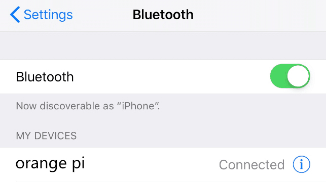
To connect to a Bluetooth device, you need to install the pulseaudio-module-bluetooth software package, and then start the pulseaudio service
orangepi@orangepi:~$ sudo apt update
orangepi@orangepi:~$ sudo apt -y install pulseaudio-module-bluetooth
orangepi@orangepi:~$ pulseaudio --start
How to connect Bluetooth devices
orangepi@orangepi:~$ sudo bluetoothctl
Agent registered
[bluetooth]# paired-devices #View the MAC address of a paired Bluetooth device
Device DC:72:9B:4C:F4:CF orangepi
[bluetooth]# connect DC:72:9B:4C:F4:CF #Connect to Bluetooth device using MAC address
Attempting to connect to DC:72:9B:4C:F4:CF
[CHG] Device DC:72:9B:4C:F4:CF Connected: yes
Connection successful
[CHG] Device DC:72:9B:4C:F4:CF ServicesResolved: yes
[CHG] Controller 10:11:12:13:14:15 Discoverable: no
[orangepi]# #If this prompt appears, the connection is successful.
After connecting the Bluetooth device, you can see the prompt that the audio for calls and media has been connected in the Bluetooth configuration interface of the Android phone.

USB interface test
|
The USB interface can be connected to a USB hub to expand the number of USB interfaces. |
USB interface extension description
As shown in the figure below, there are only two Type-C USB2.0 interfaces on the main board of the development board, which cannot directly connect USB Type-A mice, keyboards and other USB devices.

If you only purchased the motherboard and not the 24pin expansion board, you can prepare a Type-C to USB cable as shown in the figure below, plug one end of the Type-C interface into the Type-C interface of the motherboard, and then plug the other end into You can connect USB devices such as mouse and keyboard. If you feel that one USB interface is not enough, you can also expand multiple USB interfaces through USB Hub.

If you purchase a 24pin expansion board, you do not need a Type-C to USB cable, because the 24pin expansion board can expand two USB2.0 interfaces.

How to set USB0 to HOST mode
As shown in the figure below, there are two Type-C interfaces on the main board of the development board: USB0 and USB1. Both of these interfaces can be used to power the development board, and they can also be used as USB2.0 HOST interfaces. The difference between USB0 and USB1 is that in addition to being set to HOST mode, USB0 can also be set to Device mode, while USB1 only has HOST mode
USB0 of the Linux system released by Orange Pi is set to Device mode by default, so when there is no need to use USB0 Device mode, it is recommended to use USB0 for power supply, so that USB1 can be used directly to connect USB devices
If you need to use USB0 to connect USB devices, you need to set USB0 to HOST mode. The method is as follows:
First run orangepi-config. Ordinary users remember to add sudo permissions.
orangepi@orangepi:~$ sudo orangepi-config
Then select System
Then select Hardware
Then use the keyboard's arrow keys to locate the location shown in the picture below, and then use the space to select usb0-host

Then select <Save>to save
Then select <Back>
Then select <Reboot>to restart the system to make the configuration take effect.
After restarting, USB0 can use USB devices such as mouse and keyboard normally.

Connect USB mouse or keyboard to test
- Insert the USB interface keyboard into the USB interface of the Orange Pi development board
- Connect the Orange Pi development board to the HDMI display
- If the mouse or keyboard can operate the operating system normally, it means that the USB interface is working normally (the mouse can only be used in the desktop version of the system)
Connect USB storage device for testing
- First insert the U disk or USB mobile hard disk into the USB interface of the Orange Pi development board
- Execute the following command. If you can see the output of sdX, it means the USB disk is successfully recognized.
orangepi@orangepi:~$ cat /proc/partitions | grep "sd*"
major minor #blocksname
8030044160 sda
8130043119 sda1
- Use the mount command to mount the U disk to /mnt, and then you can view the files in the U disk
|
orangepi@orangepi:~$ sudo mount /dev/sda1 /mnt/ orangepi@orangepi:~$ ls /mnt/ test.txt |
- After mounting, you can check the capacity usage and mount point of the U disk through the df -h command.
|
orangepi@orangepi:~$ df -h | grep "sd" /dev/sda1 29G 208K 29G 1% /mnt |
USB Ethernet card test
- The currently tested and usable USB Ethernet cards are as follows. Among them, the RTL8153 USB Gigabit network card can be used normally when inserted into the USB 2.0 Host interface of the development board for testing, but the speed cannot reach Gigabit. Please note this.
serial number model 1 RTL8152B USB 100M network card 2 RTL8153 USB Gigabit network card
First insert the USB network card into the USB interface of the development board, and then insert the network cable into the USB network card to ensure that the network cable can access the Internet normally. If you can see the following log information through the dmesg command, it means that the USB network card is recognized normally.
orangepi@orangepi:~$ dmesg | tail
[ 121.985016] usb 3-1: USB disconnect, device number 2
[ 126.873772] sunxi-ehci 5311000.ehci3-controller: ehci_irq: highspeed device connect
[ 127.094054] usb 3-1: new high-speed USB device number 3 using sunxi-ehci
[ 127.357472] usb 3-1: reset high-speed USB device number 3 using sunxi-ehci
[ 127.557960] r8152 3-1:1.0 eth1: v1.08.9
[ 127.602642] r8152 3-1:1.0 enx00e04c362017: renamed from eth1
[ 127.731874] IPv6: ADDRCONF(NETDEV_UP): enx00e04c362017: link is not ready
[ 127.763031] IPv6: ADDRCONF(NETDEV_UP): enx00e04c362017: link is not ready
[ 129.892465] r8152 3-1:1.0 enx00e04c362017: carrier on
[ 129.892583] IPv6: ADDRCONF(NETDEV_CHANGE): enx00e04c362017: link becomes ready
Then you can see the device node of the USB network card and the automatically assigned IP address through the ifconfig command
orangepi@orangepi:~$ sudo ifconfig
enx00e04c362017: flags=4163<UP,BROADCAST,RUNNING,MULTICAST> mtu 1500
inet 192.168.1.177 netmask 255.255.255.0 broadcast 192.168.1.255
inet6 fe80::681f:d293:4bc5:e9fd prefixlen 64 scopeid 0x20<link>
ether 00:e0:4c:36:20:17 txqueuelen 1000 (Ethernet)
RX packets 1849 bytes 134590 (134.5 KB)
RX errors 0 dropped 125 overruns 0 frame 0
TX packets 33 bytes 2834 (2.8 KB)
TX errors 0 dropped 0 overruns 0 carrier 0 collisions 0
The command to test network connectivity is as follows
orangepi@orangepi:~$ ping www.baidu.com -I enx00e04c362017
PING www.a.shifen.com (14.215.177.38) from 192.168.1.12 eth0: 56(84) bytes of data.
64 bytes from 14.215.177.38 (14.215.177.38): icmp_seq=1 ttl=56 time=6.74 ms
64 bytes from 14.215.177.38 (14.215.177.38): icmp_seq=2 ttl=56 time=6.80 ms
64 bytes from 14.215.177.38 (14.215.177.38): icmp_seq=3 ttl=56 time=6.26 ms
64 bytes from 14.215.177.38 (14.215.177.38): icmp_seq=4 ttl=56 time=7.27 ms
^C
--- www.a.shifen.com ping statistics ---
4 packets transmitted, 4 received, 0% packet loss, time 3002ms
rtt min/avg/max/mdev = 6.260/6.770/7.275/0.373 ms
USB camera test
First insert the USB camera into the USB interface of the Orange Pi development board
Then you can see through the lsmod command that the kernel automatically loads the following modules
orangepi@orangepi:~$ lsmod
Module Size Used by
uvcvideo 106496 0
Through the v4l2-ctl command, you can see that the device node information of the USB camera is/dev/video0
orangepi@orangepi:~$ sudo apt update
orangepi@orangepi:~$ sudo apt install -y v4l-utils
orangepi@orangepi:~$ v4l2-ctl --list-devices
USB 2.0 Camera (usb-sunxi-ehci-1):
/dev/video0
Note that the l in v4l2 is the lowercase letter l, not the number 1.
In addition, the serial number of the video may not always be video0, please refer to what you actually see.
Use fswebcam to test the USB camera
Install fswebcam
orangepi@orangepi:~$ sudo apt update
orangepi@orangepi:~$ sudo apt-get install -y fswebcam
After installing fswebcam, you can use the following command to take pictures
a) -d Option to specify the device node of the USB camera
b) --no-banner Used to remove watermarks from photos
c) -r option is used to specify the resolution of the photo
d) -S Option to skip previous frames
e) ./image.jpg Used to set the name and path of the generated photo
orangepi@orangepi:~$ sudo fswebcam -d /dev/video0 \
--no-banner -r 1280x720 -S 5 ./image.jpg
In the server version of Linux system, after taking the picture, you can use the scp command to transfer the taken picture to the Ubuntu PC for mirror viewing.
orangepi@orangepi:~$ scp image.jpg test@192.168.1.55:/home/test (Modify the IP address and path according to the actual situation)
In the desktop version of Linux system, you can directly view the captured pictures through the HDMI display
Use mjpg-streamer to test the USB camera
Download mjpg-streamer
a) Github download address:
orangepi@orangepi:~$ git clone https://github.com/jacksonliam/mjpg-streamer
b) The image download address of Gitee is:
orangepi@orangepi:~$ git clone https://gitee.com/leeboby/mjpg-streamer
Install dependent software packages
a) Ubuntu system
orangepi@orangepi:~$ sudo apt-get install -y cmake libjpeg8-dev
b) Debian system
orangepi@orangepi:~$ sudo apt-get install -y cmake libjpeg62-turbo-dev
Compile and install mjpg-streamer
orangepi@orangepi:~$ cd mjpg-streamer/mjpg-streamer-experimental
orangepi@orangepi:~/mjpg-streamer/mjpg-streamer-experimental$ make -j4
orangepi@orangepi:~/mjpg-streamer/mjpg-streamer-experimental$ sudo make install
Then enter the following command to start mjpg_streamer
Note that the serial number of the video is not always video0, please refer to what you actually see.
orangepi@orangepi:~/mjpg-streamer/mjpg-streamer-experimental$ export LD_LIBRARY_PATH=.
orangepi@orangepi:~/mjpg-streamer/mjpg-streamer-experimental$ sudo ./mjpg_streamer -i "./input_uvc.so -d \
/dev/video0 -u -f 30" -o "./output_http.so -w ./www"
Then enter [the IP address of the development board: 8080] in the Ubuntu PC or Windows PC or mobile phone browser on the same LAN as the development board to see the video output by the camera.
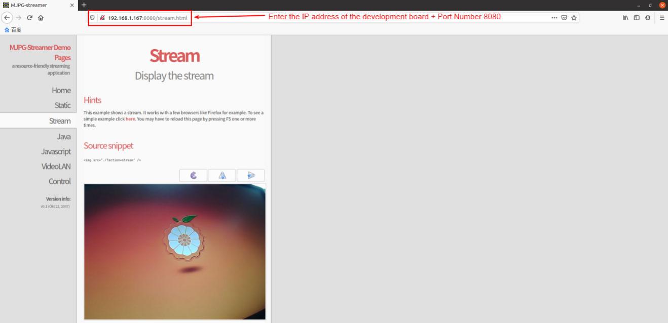

Audio test
How to play audio using the command line
Headphone interface audio playback test
There is no headphone interface on the main board of the development board. We can expand it through a 24pin expansion board.
Use the aplay -l command to view the sound card devices supported by the Linux system
The output of the linux5.4 system is as follows, where card 0: audiocodec is the sound card device required for headphone playback
root@orangepi:~# aplay -l
**** List of PLAYBACK Hardware Devices ****
card 0: audiocodec [audiocodec], device 0: soc@3000000:codec_plat-5096000.codec 5096000.codec-0 []
Subdevices: 1/1
Subdevice #0: subdevice #0
The output of the b.linux6.1 system is as follows, where audiocodec is the sound card device required for headphone playback.
root@orangepi:~# aplay -l
**** List of PLAYBACK Hardware Devices ****
card 0: audiocodec [audiocodec], device 0: CDC PCM Codec-0 [CDC PCM Codec-0]
Subdevices: 1/1
Subdevice #0: subdevice #0
Then use the aplay command to play the audio, and the sound can be heard through the headphones
root@orangepi:~# aplay -D hw:0,0 /usr/share/sounds/alsa/audio.wav
Playing WAVE 'audio.wav' : Signed 16 bit Little Endian, Rate 44100 Hz, Stereo
If there is noise during the headphone test, please pull out some of the headphones and do not plug them all the way in.
HDMI audio playback test
First use the Mini HDMI to HDMI cable to connect the Orange Pi development board to the TV (other HDMI displays need to ensure that they can play audio)
HDMI audio playback does not require other settings, just use the aplay command to play directly
root@orangepi:~# aplay -D hw:2,0 /usr/share/sounds/alsa/audio.wav
Test audio methods on desktop systems
First open the file manager
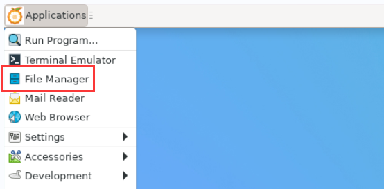
Then find the following file (if there is no such audio file in the system, you can upload an audio file to the system yourself)
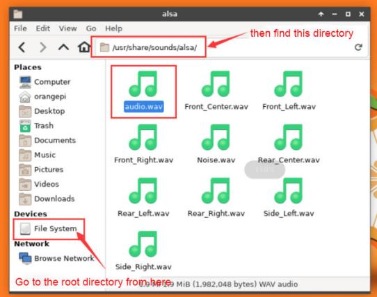
Then select the audio.wav file, right-click and select open with vlc to start playing.
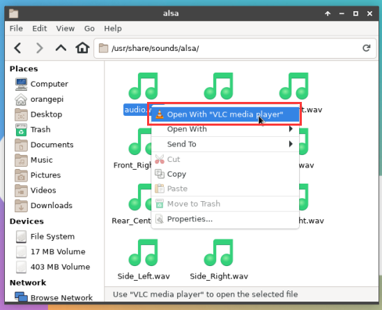
How to switch between different audio devices such as HDMI playback and headphone playback
First open the volume control interface
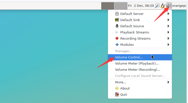
When playing audio, the audio device options that can be used by the Playback software will be displayed in Playback, as shown in the figure below. Here you can set which audio device needs to be played.
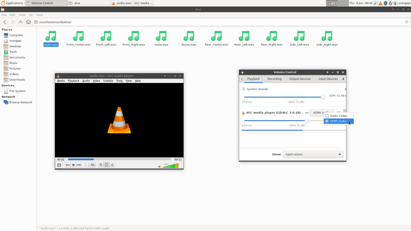


Infrared reception test
There is no infrared receiver on the main board of the development board. We can expand it through a 24pin expansion board.
Install ir-keytable infrared test software
|
orangepi@orangepi:~$ sudo apt update orangepi@orangepi:~$ sudo apt-get install -y ir-keytable |
Then execute ir-keytable to view the information of the infrared device
- linux5.4 system output is as follows
- Name: sunxi-ir
- Driver: sunxi-rc-recv
- Default keymap: rc_map_sunxi
- Input device: /dev/input/event1
- LIRC device: /dev/lirc0
- Attached BPF protocols: Operation not permitted
- Supported kernel protocols: lirc nec
- Enabled kernel protocols: lirc nec
- bus: 25, vendor/product: 0001:0001, version: 0x0100
- Repeat delay = 500 ms, repeat period = 125 ms
orangepi@orangepi:~$ ir-keytable
Found /sys/class/rc/rc0/ with:
The output of the linux6.1 system is as follows
orangepi@orangepi:~$ ir-keytable
Found /sys/class/rc/rc0/ with:
Name: sunxi-ir
Driver: sunxi-ir
Default keymap: rc-empty
Input device: /dev/input/event5
LIRC device: /dev/lirc0
Attached BPF protocols: Operation not permitted
Supported kernel protocols: lirc rc-5 rc-5-sz jvc sony nec sanyo mce_kbd rc-6 sharp xmp imon rc-mm
Enabled kernel protocols: lirc
bus: 25, vendor/product: 0001:0001, version: 0x0100
Repeat delay = 500 ms, repeat period = 125 ms
Before testing the infrared reception function, you need to prepare an Orange Pi-specific infrared remote control. Other remote controls do not support it.

Then enter the ir-keytable -t command in the terminal, and then use the infrared remote control to press the button against the infrared receiver of the Orange Pi development board to see the received key code in the terminal.
- linux5.4 system output is as follows
orangepi@orangepi:~$ sudo ir-keytable -t
Testing events. Please, press CTRL-C to abort.
1598339152.260376: event type EV_MSC(0x04): scancode = 0xfb0413
1598339152.260376: event type EV_SYN(0x00).
1598339152.914715: event type EV_MSC(0x04): scancode = 0xfb0410
linux6.1 system output is as follows
orangepi@orangepi:~$ sudo ir-keytable -c -p NEC -t
Old keytable cleared
Protocols changed to nec
Testing events. Please, press CTRL-C to abort.
202.063219: lirc protocol(nec): scancode = 0x45c
202.063249: event type EV_MSC(0x04): scancode = 0x45c
202.063249: event type EV_SYN(0x00).

Temperature sensor
How to check the temperature in linux5.4 system
H618 has a total of 4 temperature sensors. The command to view the temperature is as follows:
|
The displayed temperature value needs to be divided by 1000, and the unit is Celsius. |
- sensor0: CPU temperature sensor, the first command is used to view the type of temperature sensor, the second command is used to view the value of the temperature sensor
|
orangepi@orangepi:~$ cat /sys/class/thermal/thermal_zone0/type cpu_thermal_zone orangepi@orangepi:~$ cat /sys/class/thermal/thermal_zone0/temp 57734 |
sensor1: DDR temperature sensor, the first command is used to view the type of temperature sensor, the second command is used to view the value of the temperature sensor
orangepi@orangepi:~$ cat /sys/class/thermal/thermal_zone1/type
ddr_thermal_zone
orangepi@orangepi:~$ cat /sys/class/thermal/thermal_zone1/temp
57410
sensor2: GPU temperature sensor, the first command is used to view the type of temperature sensor, the second command is used to view the value of the temperature sensor
orangepi@orangepi:~$ cat /sys/class/thermal/thermal_zone2/type
gpu_thermal_zone
orangepi@orangepi:~$ cat /sys/class/thermal/thermal_zone2/temp
59273
sensor3: VE's temperature sensor. The first command is used to view the type of temperature sensor, and the second command is used to view the value of the temperature sensor.
orangepi@orangepi:~$ cat /sys/class/thermal/thermal_zone3/type
ve_thermal_zone
orangepi@orangepi:~$ cat /sys/class/thermal/thermal_zone3/temp
58949
How to check the temperature in linux6.1 system
|
orangepi@orangepi:~$ sensors cpu_thermal-virtual-0 Adapter: Virtual device temp1: +47.4°C (crit = +110.0°C)
Adapter: Virtual device temp1: +48.7°C (crit = +110.0°C)
Adapter: Virtual device temp1: +47.8°C (crit = +110.0°C)
Adapter: Virtual device temp1: +47.2°C (crit = +110.0°C) |
40 Pin Interface pin description
|
Note: The pin header on the 40pin interface is not soldered by default, and you need to solder it yourself before it can be used. |
For the order of the 40 Pin interface pins of the Orange Pi Zero 2w development board, please refer to the silk screen diagram on the development board.
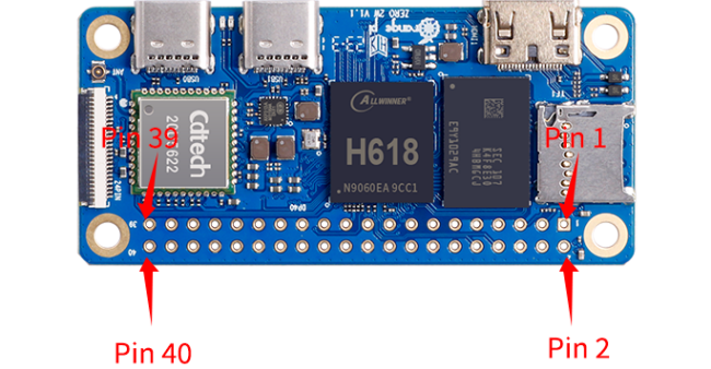
The functions of the 40 Pin interface pins on the development board are as shown in the table below

| GPIO NO. | GPIO | Function | pin |
| 3.3V | 1 | ||
| 264 | PI8 | TWI1-SDA | 3 |
| 263 | PI7 | TWI1-SCL | 5 |
| 269 | PI13 | PWM3/UART4_TX | 7 |
| GND | 9 | ||
| 226 | PH2 | UART5_TX | 11 |
| 227 | PH3 | UART5_RX | 13 |
| 261 | PI5 | TWI0_SCL/UART2_TX | 15 |
| 3.3V | 17 | ||
| 231 | PH7 | SPI1_MOSI | 19 |
| 232 | PH8 | SPI1_MISO | 21 |
| 230 | PH6 | SPI1_CLK | 23 |
| GND | 25 | ||
| 266 | PI10 | TWI2-SDA/UART3_RX | 27 |
| 256 | PI0 | 29 | |
| 271 | PI15 | 31 | |
| 268 | PI12 | PWM2 | 33 |
| 258 | PI2 | 35 | |
| 272 | PI16 | 37 | |
| GND | 39 |
| pin | Function | GPIO | GPIO NO. |
| 2 | 5V | ||
| 4 | 5V | ||
| 6 | GND | ||
| 8 | UART0_TX | PH0 | 224 |
| 10 | UART0_RX | PH1 | 225 |
| 12 | PI1 | 257 | |
| 14 | GND | ||
| 16 | PWM4/UART4_RX | PI14 | 270 |
| 18 | PH4 | 228 | |
| 20 | GND | ||
| 22 | TWI0_SDA/UART2_RX | PI6 | 262 |
| 24 | SPI1_CS0 | PH5 | 229 |
| 26 | SPI1_CS1 | PH9 | 233 |
| 28 | TWI2-SCL/UART3_TX | PI9 | 265 |
| 30 | GND | ||
| 32 | PWM1 | PI11 | 267 |
| 34 | GND | ||
| 36 | PC12 | 76 | |
| 38 | PI4 | 260 | |
| 40 | PI3 | 259 |
- There are a total of 28 GPIO ports in the 40pin interface. The high-level voltage of all GPIO ports is 3.3v
How to install wiringOP
|
Note that wiringOP is already pre-installed in the linux image released by Orange Pi. Unless the wiringOP code is updated, there is no need to re-download, compile and install, you can just use it directly.
orangepi-build/external/cache/debs/arm64/wiringpi_x.xx.deb
 WiringOP currently mainly adapts to the functions of setting GPIO port input and output, setting GPIO port output high and low levels, and setting pull-up and pull-down resistors. Functions such as hardware PWM cannot be used. |
Download the code of wiringOP
orangepi@orangepi:~$ sudo apt update
orangepi@orangepi:~$ sudo apt install -y git
orangepi@orangepi:~$ git clone https://github.com/orangepi-xunlong/wiringOP.git -b next
Note that the source code needs to download the code of wiringOP next branch. Please don't miss the -b next parameter.
If there is a problem downloading the code from GitHub, you can directly use the wiringOP source code that comes with the Linux image. The storage location is: /usr/src/wiringOP.
Compile and install wiringOP
orangepi@orangepi:~$ cd wiringOP
orangepi@orangepi:~/wiringOP$ sudo ./build clean
orangepi@orangepi:~/wiringOP$ sudo ./build
The output of the test gpio readall command is as follows
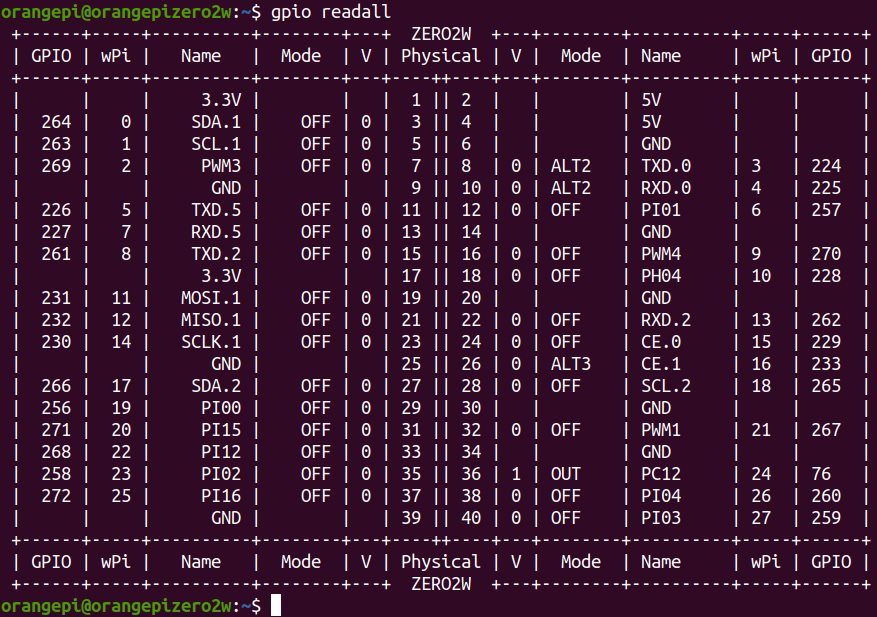
40pin interface GPIO, I2C, UART, SPI and PWM testing
|
Note: The pin header on the 40pin interface is not soldered by default, and you need to solder it yourself before it can be used. |
40pin GPIO port test
The following uses pin No. 7 - corresponding to GPIO PI13 - corresponding to wPi serial number 2 - as an example to demonstrate how to set the high and low levels of the GPIO port.
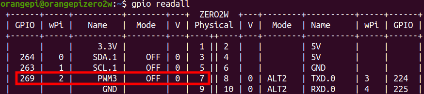
First set the GPIO port to output mode, and the third parameter needs to be the serial number of the wPi corresponding to the input pin.
root@orangepi:~/wiringOP# gpio mode 2 out
Then set the GPIO port to output a low level. After setting, you can use a multimeter to measure the voltage value of the pin. If it is 0v, it means the low level is set successfully.
root@orangepi:~/wiringOP# gpio write 2 0
Then set the GPIO port to output a high level. After setting, you can use a multimeter to measure the voltage value of the pin. If it is 3.3v, it means the setting of the high level is successful.
root@orangepi:~/wiringOP# gpio write 2 1
The setting method for other pins is similar. You only need to modify the serial number of wPi to the serial number corresponding to the pin.

How to set the pull-down resistor of 40 Pin GPIO port
The following uses pin No. 7—corresponding to GPIO PI13—corresponding to wPi serial number 2—as an example to demonstrate how to set the pull-up and pull-down resistors of the GPIO port.
First, you need to set the GPIO port to input mode, and the third parameter needs to be the serial number of the wPi corresponding to the input pin.
root@orangepi:~/wiringOP# gpio mode 2 in
After setting to input mode, execute the following command to set the GPIO port to pull-up mode.
root@orangepi:~/wiringOP# gpio mode 2 up
Then enter the following command to read the level of the GPIO port. If the level is 1, it means that the pull-up mode is set successfully.
root@orangepi:~/wiringOP# gpio read 2
1
Then execute the following command to set the GPIO port to pull-down mode
root@orangepi:~/wiringOP# gpio mode 2 down
Then enter the following command to read the level of the GPIO port. If the level is 0, it means that the pull-down mode is set successfully.
root@orangepi:~/wiringOP# gpio read 2
0
40pin SPI test
- As can be seen from the table below, the spi available for the 40pin interface is spi1, and there are two chip select pins cs0 and cs1
GPIO NO. GPIO Function pin 3.3V 1 264 PI8 TWI1-SDA 3 263 PI7 TWI1-SCL 5 269 PI13 PWM3/UART4_TX 7 GND 9 226 PH2 UART5_TX 11 227 PH3 UART5_RX 13 261 PI5 TWI0_SCL/UART2_TX 15 3.3V 17 231 PH7 SPI1_MOSI 19 232 PH8 SPI1_MISO 21 230 PH6 SPI1_CLK 23 GND 25 266 PI10 TWI2-SDA/UART3_RX 27 256 PI0 29 271 PI15 31 268 PI12 PWM2 33 258 PI2 35 272 PI16 37 GND 39
| pin | Function | GPIO | GPIO NO. |
| 2 | 5V | ||
| 4 | 5V | ||
| 6 | GND | ||
| 8 | UART0_TX | PH0 | 224 |
| 10 | UART0_RX | PH1 | 225 |
| 12 | PI1 | 257 | |
| 14 | GND | ||
| 16 | PWM4/UART4_RX | PI14 | 270 |
| 18 | PH4 | 228 | |
| 20 | GND | ||
| 22 | TWI0_SDA/UART2_RX | PI6 | 262 |
| 24 | SPI1_CS0 | PH5 | 229 |
| 26 | SPI1_CS1 | PH9 | 233 |
| 28 | TWI2-SCL/UART3_TX | PI9 | 265 |
| 30 | GND | ||
| 32 | PWM1 | PI11 | 267 |
| 34 | GND | ||
| 36 | PC12 | 76 | |
| 38 | PI4 | 260 | |
| 40 | PI3 | 259 |
In Linux systems, spi1 is turned off by default and needs to be turned on manually before it can be used. The opening steps are as follows:
First run orangepi-config. Ordinary users remember to add sudo permissions.
orangepi@orangepi:~$ sudo orangepi-config
Then select System
Then select Hardware
Then use the keyboard's arrow keys to locate the position shown in the figure below, and then use the space to select the dtbo configuration of the SPI you want to open.
dtbo configuration illustrate spi1-cs0-cs1-spidev Open cs0 and cs1 of spi1 at the same time spi1-cs0-spidev Only open cs0 of spi1 spi1-cs1-spidev Only open cs1 of spi1 
Then select <Save> to save
Then select <Back>
Then select <Reboot>to restart the system to make the configuration take effect.

Then check whether there is a spidev1.x device node in the Linux system. If it exists, it means that the SPI1 configuration has taken effect.
orangepi@orangepi:~$ ls /dev/spidev1*
/dev/spidev1.0 /dev/spidev1.1
Note that only when you open spi1-cs0-cs1-spidev, you will see the device nodes of the two spi.
Next, start the spi loopback test. Do not short-circuit the mosi and miso pins of SPI1 first. The output result of running spidev_test is as follows. You can see that the data of TX and RX are inconsistent.
orangepi@orangepi:~$ sudo spidev_test -v -D /dev/spidev1.0
spi mode: 0x0
bits per word: 8
max speed: 500000 Hz (500 KHz)
TX | FF FF FF FF FF FF 40 00 00 00 00 95 FF FF FF FF FF FF FF FF FF FF FF FF FF FF FF FF FF FF F0 0D | ......@.…▒..................▒.
RX | FF FF FF FF FF FF FF FF FF FF FF FF FF FF FF FF FF FF FF FF FF FF FF FF FF FF FF FF FF FF FF FF | ............................….
Then short-circuit the two pins of SPI1 mosi (pin 19 in the 40pin interface) and miso (pin 21 in the 40pin interface) and then run spidev_test. The output is as follows. You can see the sending and receiving The data is the same, indicating that the loopback test passed.
orangepi@orangepi:~$ sudo spidev_test -v -D /dev/spidev1.0
spi mode: 0x0
bits per word: 8
max speed: 500000 Hz (500 KHz)
TX | FF FF FF FF FF FF 40 00 00 00 00 95 FF FF FF FF FF FF FF FF FF FF FF FF FF FF FF FF FF FF F0 0D | ......@.…▒..................▒.
RX | FF FF FF FF FF FF 40 00 00 00 00 95 FF FF FF FF FF FF FF FF FF FF FF FF FF FF FF FF FF FF F0 0D | ......@.…▒..................▒.
40pin I2C test
- As can be seen from the table below, the i2c available for the 40pin interface are i2c0, i2c1 and i2c2
GPIO NO. GPIO Function pin 3.3V 1 264 PI8 TWI1-SDA 3 263 v TWI1-SCL 5 269 PI13 PWM3/UART4_TX 7 GND 9 226 PH2 UART5_TX 11 227 PH3 UART5_RX 13 261 PI5 TWI0_SCL/UART2_TX 15 3.3V 17 231 PH7 SPI1_MOSI 19 232 PH8 SPI1_MISO 21 230 PH6 SPI1_CLK 23 GND 25 266 PI10 TWI2-SDA/UART3_RX 27 256 PI0 29 271 PI15 31 268 PI12 PWM2 33 258 PI2 35 272 PI16 37 GND 39
| pin | Function | GPIO | GPIO NO. |
| 2 | 5V | ||
| 4 | 5V | ||
| 6 | GND | ||
| 8 | UART0_TX | PH0 | 224 |
| 10 | UART0_RX | PH1 | 225 |
| 12 | PI1 | 257 | |
| 14 | GND | ||
| 16 | PWM4/UART4_RX | PI14 | 270 |
| 18 | PH4 | 228 | |
| 20 | GND | ||
| 22 | TWI0_SDA/UART2_RX | PI6 | 262 |
| 24 | SPI1_CS0 | PH5 | 229 |
| 26 | SPI1_CS1 | PH9 | 233 |
| 28 | TWI2-SCL/UART3_TX | PI9 | 265 |
| 30 | GND | ||
| 32 | PWM1 | PI11 | 267 |
| 34 | GND | ||
| 36 | PC12 | 76 | |
| 38 | PI4 | 260 | |
| 40 | PI3 | 259 |
i2c is turned off by default in Linux systems and needs to be turned on manually to use it. The opening steps are as follows:
First run orangepi-config. Ordinary users remember to add sudo permissions.
orangepi@orangepi:~$ sudo orangepi-config
Then select System
Then select Hardware
Then use the keyboard's arrow keys to locate the position shown in the picture below, and then use the space to select the corresponding i2c configuration in the picture below.
Multiplexing function in 40pin Corresponding dtbo configuration 40pin - i2c0 pi-i2c0 40pin - i2c1 pi-i2c1 40pin - i2c2 pi-i2c2 
Then select <Save> to save
Then select <Back>
Then select <Reboot> to restart the system to make the configuration take effect.

After starting the Linux system, first confirm that there is an open i2c device node under /dev
orangepi@orangepi:~$ ls /dev/i2c-*
/dev/i2c-*
Sometimes the i2c device node and the i2c bus serial number do not correspond one to one. For example, the i2c device node of the i2c1 bus may be /dev/i2c-3.
The method to accurately confirm the device node under /dev corresponding to the i2c bus is:
First run the following command to check the corresponding relationship of i2c
orangepi@orangepizero2w:~$ ls /sys/devices/platform/soc*/*/i2c-* | grep "i2c-[0-9]"
/sys/devices/platform/soc/5002000.i2c/i2c-0:
/sys/devices/platform/soc/5002400.i2c/i2c-3:
/sys/devices/platform/soc/5002800.i2c/i2c-4:
/sys/devices/platform/soc/5002c00.i2c/i2c-5:
/sys/devices/platform/soc/6000000.hdmi/i2c-2:
/sys/devices/platform/soc/7081400.i2c/i2c-1:
In the above output
a) 5002000 is the register base address of the i2c0 bus, and i2c-0 shown behind it is its corresponding i2c device node
b) 5002400 is the register base address of the i2c1 bus, and i2c-3 shown behind it is its corresponding i2c device node
c) 5002800 is the register base address of the i2c2 bus, and i2c-4 shown behind it is its corresponding i2c device node
Then start testing i2c, first install i2c-tools
orangepi@orangepi:~$ sudo apt-get update
orangepi@orangepi:~$ sudo apt-get install -y i2c-tools
Then connect an i2c device to the i2c pin of the 40pin connector
Then use the i2cdetect -y x x command. If the address of the connected i2c device can be detected, it means that i2c can be used normally.
Note that x in the i2cdetect -y x command needs to be replaced with the serial number of the device node corresponding to the i2c bus.
Different i2c device addresses are different. The 0x50 address in the picture below is just an example. Please refer to what you actually see.
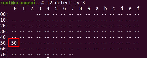

40pin UART test
- As can be seen from the table below, the available uarts are uart2, uart3, uart4 and uart5. Please note that uart0 is set as a debugging serial port by default. Please do not use uart0 as a normal serial port.
GPIO NO. GPIO Function pin 3.3V 1 264 PI8 TWI1-SDA 3 263 PI7 TWI1-SCL 5 269 PI13 PWM3/UART4_TX 7 GND 9 226 PH2 UART5_TX 11 227 PH3 UART5_RX 13 261 PI5 TWI0_SCL/UART2_TX 15 3.3V 17 231 PH7 SPI1_MOSI 19 232 PH8 SPI1_MISO 21 230 PH6 SPI1_CLK 23 GND 25 266 PI10 TWI2-SDA/UART3_RX 27 256 PI0 29 271 PI15 31 268 PI12 PWM2 33 258 PI2 35 272 PI16 37 GND 39
| pin | Function | GPIO | GPIO NO. |
| 2 | 5V | ||
| 4 | 5V | ||
| 6 | GND | ||
| 8 | UART0_TX | PH0 | 224 |
| 10 | UART0_RX | PH1 | 225 |
| 12 | PI1 | 257 | |
| 14 | GND | ||
| 16 | PWM4/UART4_RX | PI14 | 270 |
| 18 | PH4 | 228 | |
| 20 | GND | ||
| 22 | TWI0_SDA/UART2_RX | PI6 | 262 |
| 24 | SPI1_CS0 | PH5 | 229 |
| 26 | SPI1_CS1 | PH9 | 233 |
| 28 | TWI2-SCL/UART3_TX | PI9 | 265 |
| 30 | GND | ||
| 32 | PWM1 | PI11 | 267 |
| 34 | GND | ||
| 36 | PC12 | 76 | |
| 38 | PI4 | 260 | |
| 40 | PI3 | 259 |
In Linux systems, uart is turned off by default and needs to be turned on manually before it can be used. The opening steps are as follows:
First run orangepi-config. Ordinary users remember to add sudo permissions.
orangepi@orangepi:~$ sudo orangepi-config
Then select System
Then select Hardware
Then use the keyboard's arrow keys to locate the position shown in the picture below, and then use the space to select the serial port you want to open.
Multiplexing function in 40pin Corresponding dtbo configuration 40pin - uart2 pi-uart2 40pin - uart3 pi-uart3 40pin - uart4 pi-uart4 40pin - uart5 ph-uart5 
Then select <Save> to save
Then select <Back>
Then select <Reboot> to restart the system to make the configuration take effect.

After entering the Linux system, first confirm whether there is a uart5 device node under /dev
Note that the linux5.4 system is /dev/ttyASx.
orangepi@orangepi:~$ ls /dev/ttyS*
/dev/ttySx
Then start testing the uart interface. First use Dupont wire to short-circuit the rx and tx pins of the uart interface to be tested.
Use the gpio command in wiringOP to test the loopback function of the serial port as shown below. If you can see the following print, it means the serial port communication is normal.
Note that the last x in the gpio serial /dev/ttySx command needs to be replaced with the serial number of the corresponding uart device node.
orangepi@orangepi:~$ gpio serial /dev/ttySx # linux-6.1 test command
orangepi@orangepi:~$ gpio serial /dev/ttyASx # linux-5.4 test command
Out: 0: -> 0
Out: 1: -> 1
Out: 2: -> 2
Out: 3: -> 3^C
PWM test method
- As can be seen from the following table, the available pwm are pwm1, pwm2, pwm3 and pwm4.
GPIO NO. GPIO Function Pin 3.3V 1 264 PI8 TWI1-SDA 3 263 PI7 TWI1-SCL 5 269 PI13 PWM3/UART4_TX 7 GND 9 226 PH2 UART5_TX 11 227 PH3 UART5_RX 13 261 PI5 TWI0_SCL/UART2_TX 15 3.3V 17 231 PH7 SPI1_MOSI 19 232 PH8 SPI1_MISO 21 230 PH6 SPI1_CLK 23 GND 25 266 PI10 TWI2-SDA/UART3_RX 27 256 PI0 29 271 PI15 31 268 PI12 PWM2 33 258 PI2 35 272 PI16 37 GND 39
| Pin | Function | GPIO | GPIO NO. |
| 2 | 5V | ||
| 4 | 5V | ||
| 6 | GND | ||
| 8 | UART0_TX | PH0 | 224 |
| 10 | UART0_RX | PH1 | 225 |
| 12 | PI1 | 257 | |
| 14 | GND | ||
| 16 | PWM4/UART4_RX | PI14 | 270 |
| 18 | PH4 | 228 | |
| 20 | GND | ||
| 22 | TWI0_SDA/UART2_RX | PI6 | 262 |
| 24 | SPI1_CS0 | PH5 | 229 |
| 26 | SPI1_CS1 | PH9 | 233 |
| 28 | TWI2-SCL/UART3_TX | PI9 | 265 |
| 30 | GND | ||
| 32 | PWM1 | PI11 | 267 |
| 34 | GND | ||
| 36 | PC12 | 76 | |
| 38 | PI4 | 260 | |
| 40 | PI3 | 259 |
pwm is turned off by default in Linux systems and needs to be turned on manually to use it. The opening steps are as follows:
First run orangepi-config. Ordinary users remember to add sudo permissions.
orangepi@orangepi:~$ sudo orangepi-config
Then select System
Then select Hardware
Then use the keyboard's arrow keys to locate the position shown in the figure below, and then use the space to select the configuration corresponding to the pwm you want to open.

Then select <Save> to save
Then select <Back>
Then select <Reboot> to restart the system to make the configuration take effect.
After restarting, you can start the PWM test
Please execute the following commands under the root user.
Enter the following command on the command line to make pwm1 output a 50Hz square wave
root@orangepi:~# echo 1 > /sys/class/pwm/pwmchip0/export
root@orangepi:~# echo 20000000 > /sys/class/pwm/pwmchip0/pwm1/period
root@orangepi:~# echo 1000000 > /sys/class/pwm/pwmchip0/pwm1/duty_cycle
root@orangepi:~# echo 1 > /sys/class/pwm/pwmchip0/pwm1/enable
Enter the following command on the command line to make pwm2 output a 50Hz square wave
root@orangepi:~# echo 2 > /sys/class/pwm/pwmchip0/export
root@orangepi:~# echo 20000000 > /sys/class/pwm/pwmchip0/pwm2/period
root@orangepi:~# echo 1000000 > /sys/class/pwm/pwmchip0/pwm2/duty_cycle
root@orangepi:~# echo 1 > /sys/class/pwm/pwmchip0/pwm2/enable
- Enter the following command on the command line to make pwm3 output a 50Hz square wave
root@orangepi:~# echo 3 > /sys/class/pwm/pwmchip0/export
root@orangepi:~# echo 20000000 > /sys/class/pwm/pwmchip0/pwm3/period
root@orangepi:~# echo 1000000 > /sys/class/pwm/pwmchip0/pwm3/duty_cycle
root@orangepi:~# echo 1 > /sys/class/pwm/pwmchip0/pwm3/enable
- Enter the following command on the command line to make pwm4 output a 50Hz square wave
root@orangepi:~# echo 4 > /sys/class/pwm/pwmchip0/export
root@orangepi:~# echo 20000000 > /sys/class/pwm/pwmchip0/pwm4/period
root@orangepi:~# echo 1000000 > /sys/class/pwm/pwmchip0/pwm4/duty_cycle
root@orangepi:~# echo 1 > /sys/class/pwm/pwmchip0/pwm4/enable
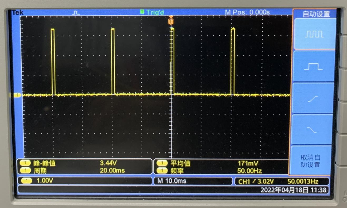


How to install and use wiringOP-Python
|
Note: The pin header on the 40pin interface is not soldered by default, and you need to solder it yourself before it can be used. |
|
wiringOP-Python is the Python language version of wiringOP library, used to operate the development board's GPIO, I2C, SPI, UART and other hardware resources in the Python program Also please note that all the following commands are operated under the root user. |
How to install wiringOP-Python
First install dependency packages
root@orangepi:~# sudo apt-get update
root@orangepi:~# sudo apt-get -y install git swig python3-dev python3-setuptools
Then use the following command to download the source code of wiringOP-Python
|
Note that the following git clone--recursive command will automatically download the source code of wiringOP, because wiringOP-Python depends on wiringOP. Please make sure there are no errors during the download process due to network problems. If there is a problem downloading the code from GitHub, you can directly use the wiringOP-Python source code that comes with the Linux image. The storage location is: /usr/src/wiringOP-Python |
|
root@orangepi:~# git clone --recursive https://github.com/orangepi-xunlong/wiringOP-Python -b next root@orangepi:~# cd wiringOP-Python root@orangepi:~/wiringOP-Python# git submodule update --init --remote |
Then use the following command to compile wiringOP-Python and install it into the Linux system of the development board
root@orangepi:~# cd wiringOP-Python
root@orangepi:~/wiringOP-Python# python3 generate-bindings.py > bindings.i
root@orangepi:~/wiringOP-Python# sudo python3 setup.py install
Then enter the following command. If helpful information is output, it means wiringOP-Python is successfully installed. Press the q key to exit the help information interface.
- wiringpi
- # This file was automatically generated by SWIG (http://www.swig.org).
- # Version 4.0.2
- #
- # Do not make changes to this file unless you know what you are doing--modify
- # the SWIG interface file instead.
|
root@orangepi:~/wiringOP-Python# python3 -c "import wiringpi; help(wiringpi)" Help on module wiringpi:
|
The steps to test whether wiringOP-Python is installed successfully under the python command line are as follows:
- First use the python3 command to enter the command line mode of > python3
root@orangepi:~# python3
- Then import the python module of wiringpi
>>> import wiringpi;
- Finally, enter the following command to view the help information of > wiringOP-Python. Press the q key to exit the help information > interface.
- wiringpi
- # This file was automatically generated by SWIG (http://www.swig.org).
- # Version 4.0.2
- #
- # Do not make changes to this file unless you know what you are doing--modify
- # the SWIG interface file instead.
- builtins.object
- GPIO
- I2C
- Serial
- nes
- class GPIO(builtins.object)
- | GPIO(pinmode=0)
- |
>>> help(wiringpi)
Help on module wiringpi:
NAME
DESCRIPTION
CLASSES
>>>
40pin GPIO port test
|
Like wiringOP, wiringOP-Python can also determine which GPIO pin to operate by specifying the wPi number. Because there is no command to view the wPi number in wiringOP-Python, you can only view the board's wPi number and physics through the gpio command in wiringOP Correspondence of pins. |
The following uses pin No. 7 - corresponding to GPIO PI13 - corresponding to wPi serial number 2 - as an example to demonstrate how to set the high and low levels of the GPIO port.
The steps for testing directly with commands are as follows:
First set the GPIO port to output mode, where the first parameter of the pinMode function is the serial number of the wPi corresponding to the pin, and the second parameter is the GPIO mode.
root@orangepi:~/wiringOP-Python# python3 -c "import wiringpi; \
from wiringpi import GPIO; wiringpi.wiringPiSetup() ; \
wiringpi.pinMode(2, GPIO.OUTPUT) ; "
Then set the GPIO port to output a low level. After setting, you can use a multimeter to measure the voltage value of the pin. If it is 0v, it means the low level is set successfully.
root@orangepi:~/wiringOP-Python# python3 -c "import wiringpi; \
from wiringpi import GPIO; wiringpi.wiringPiSetup() ;\
wiringpi.digitalWrite(2, GPIO.LOW)"
Then set the GPIO port to output a high level. After setting, you can use a multimeter to measure the voltage value of the pin. If it is 3.3v, it means the setting of the high level is successful.
root@orangepi:~/wiringOP-Python# python3 -c "import wiringpi; \
from wiringpi import GPIO; wiringpi.wiringPiSetup() ;\
wiringpi.digitalWrite(2, GPIO.HIGH)"
The steps for testing in the command line of python3 are as follows:
First use the python3 command to enter the command line mode of python3
root@orangepi:~# python3
Then import the python module of wiringpi
>>> import wiringpi
>>> from wiringpi import GPIO
Then set the GPIO port to output mode, where the first parameter of the pinModefunction is the serial number of the wPi corresponding to the pin, and the second parameter is the GPIO mode.
>>> wiringpi.wiringPiSetup()
0
>>> wiringpi.pinMode(2, GPIO.OUTPUT)
Then set the GPIO port to output a low level. After setting, you can use a multimeter to measure the voltage value of the pin. If it is 0v, it means the low level is set successfully.
>>> wiringpi.digitalWrite(2, GPIO.LOW)
Then set the GPIO port to output a high level. After setting, you can use a multimeter to measure the voltage value of the pin. If it is 3.3v, it means the setting of the high level is successful.
>>> wiringpi.digitalWrite(2, GPIO.HIGH)
For wiringOP-Python to set the GPIO high and low levels in the python code, you can refer to the blink.py test program in the examples. The blink.py test program will set the voltage of all GPIO ports in the 40 Pin of the development board to continuously change high and low.
root@orangepi:~/wiringOP-Python# cd examples
root@orangepi:~/wiringOP-Python/examples# ls blink.py
blink.py
root@orangepi:~/wiringOP-Python/examples# python3 blink.py
40pin SPI test
- As can be seen from the table below, the spi available for the 40pin interface is spi1, and there are two chip select pins cs0 and cs1
GPIO NO. GPIO Function Pin 3.3V 1 264 PI8 TWI1-SDA 3 263 PI7 TWI1-SCL 5 269 PI13 PWM3/UART4_TX 7 GND 9 226 PH2 UART5_TX 11 227 PH3 UART5_RX 13 261 PI5 TWI0_SCL/UART2_TX 15 3.3V 17 231 PH7 SPI1_MOSI 19 232 PH8 SPI1_MISO 21 230 PH6 SPI1_CLK 23 GND 25 266 PI10 TWI2-SDA/UART3_RX 27 256 PI0 29 271 PI15 31 268 PI12 PWM2 33 258 PI2 35 272 PI16 37 GND 39
| Pin | Function | GPIO | GPIO NO. |
| 2 | 5V | ||
| 4 | 5V | ||
| 6 | GND | ||
| 8 | UART0_TX | PH0 | 224 |
| 10 | UART0_RX | PH1 | 225 |
| 12 | PI1 | 257 | |
| 14 | GND | ||
| 16 | PWM4/UART4_RX | PI14 | 270 |
| 18 | PH4 | 228 | |
| 20 | GND | ||
| 22 | TWI0_SDA/UART2_RX | PI6 | 262 |
| 24 | SPI1_CS0 | PH5 | 229 |
| 26 | SPI1_CS1 | PH9 | 233 |
| 28 | TWI2-SCL/UART3_TX | PI9 | 265 |
| 30 | GND | ||
| 32 | PWM1 | PI11 | 267 |
| 34 | GND | ||
| 36 | PC12 | 76 | |
| 38 | PI4 | 260 | |
| 40 | PI3 | 259 |
In Linux systems, spi1 is turned off by default and needs to be turned on manually before it can be used. The opening steps are as follows:
First run orangepi-config. Ordinary users remember to add sudo permissions.
orangepi@orangepi:~$ sudo orangepi-config
Then select System
Then select Hardware
Then use the keyboard's arrow keys to locate the position shown in the figure below, and then use the space to select the dtbo configuration of the SPI you want to open.
dtbo configuration illustrate spi1-cs0-cs1-spidev Open cs0 and cs1 of spi1 at the same time spi1-cs0-spidev Only open cs0 of spi1 spi1-cs1-spidev Only open cs1 of spi1 Then select <Save> to save
Then select <Back>
Then select <Reboot> to restart the system to make the configuration take effect.
Then check whether there is a spidev1.x device node in the Linux system. If it exists, it means that the SPI1 configuration has taken effect.
orangepi@orangepi:~$ ls /dev/spidev1*
/dev/spidev1.0 /dev/spidev1.1
Note that only when you open spi1-cs0-cs1-spidev, you will see the device nodes of the two spi.
Then you can use the spidev_test.py program in examples to test the SPI loopback function. The spidev_test.py program needs to specify the following two parameters:
--channel: Specify the channel number of SPI
--port: Specify the port number of the SPI
Without shorting the mosi and miso pins of SPI1, the output result of running spidev_test.py is as follows. You can see that the data of TX and RX are inconsistent.
root@orangepi:~/wiringOP-Python# cd examples
root@orangepi:~/wiringOP-Python/examples# python3 spidev_test.py \
--channel 1 --port 0
spi mode: 0x0
max speed: 500000 Hz (500 KHz)
Opening device /dev/spidev1.1
TX | FF FF FF FF FF FF 40 00 00 00 00 95 FF FF FF FF FF FF FF FF FF FF FF FF FF FF FF FF FF FF F0 0D |......@.......…|
RX | FF FF FF FF FF FF FF FF FF FF FF FF FF FF FF FF FF FF FF FF FF FF FF FF FF FF FF FF FF FF FF FF |.............….|
Then use Dupont wire to short-circuit the txd (pin 19 in the 40pin interface) and rxd (pin 21 in the 40pin interface) of SPI1 and then run spidev_test.py. The output is as follows, you can see If the data sent and received are the same, it means that the SPI1 loopback test is normal.
root@orangepi:~/wiringOP-Python# cd examples
root@orangepi:~/wiringOP-Python/examples# python3 spidev_test.py \
--channel 1 --port 0
spi mode: 0x0
max speed: 500000 Hz (500 KHz)
Opening device /dev/spidev1.1
TX | FF FF FF FF FF FF 40 00 00 00 00 95 FF FF FF FF FF FF FF FF FF FF FF FF FF FF FF FF FF FF F0 0D |......@.......…|
RX | FF FF FF FF FF FF 40 00 00 00 00 95 FF FF FF FF FF FF FF FF FF FF FF FF FF FF FF FF FF FF F0 0D |......@.......…|
40pin I2C test
- As can be seen from the table below, the i2c available for the 40pin interface are i2c0, i2c1 and i2c2
GPIO NO. GPIO Function Pin 3.3V 1 264 PI8 TWI1-SDA 3 263 v TWI1-SCL 5 269 PI13 PWM3/UART4_TX 7 GND 9 226 PH2 UART5_TX 11 227 PH3 UART5_RX 13 261 PI5 TWI0_SCL/UART2_TX 15 3.3V 17 231 PH7 SPI1_MOSI 19 232 PH8 SPI1_MISO 21 230 PH6 SPI1_CLK 23 GND 25 266 PI10 TWI2-SDA/UART3_RX 27 256 PI0 29 271 PI15 31 268 PI12 PWM2 33 258 PI2 35 272 PI16 37 GND 39
| Pin | Function | GPIO | GPIO NO. |
| 2 | 5V | ||
| 4 | 5V | ||
| 6 | GND | ||
| 8 | UART0_TX | PH0 | 224 |
| 10 | UART0_RX | PH1 | 225 |
| 12 | PI1 | 257 | |
| 14 | GND | ||
| 16 | PWM4/UART4_RX | PI14 | 270 |
| 18 | PH4 | 228 | |
| 20 | GND | ||
| 22 | TWI0_SDA/UART2_RX | PI6 | 262 |
| 24 | SPI1_CS0 | PH5 | 229 |
| 26 | SPI1_CS1 | PH9 | 233 |
| 28 | TWI2-SCL/UART3_TX | PI9 | 265 |
| 30 | GND | ||
| 32 | PWM1 | PI11 | 267 |
| 34 | GND | ||
| 36 | PC12 | 76 | |
| 38 | PI4 | 260 | |
| 40 | PI3 | 259 |
i2c is turned off by default in Linux systems and needs to be turned on manually to use it. The opening steps are as follows:
First run orangepi-config. Ordinary users remember to add sudo permissions.
orangepi@orangepi:~$ sudo orangepi-config
Then select System
Then select Hardware
Then use the keyboard's arrow keys to locate the position shown in the picture below, and then use the space to select the corresponding i2c configuration in the picture below.
Multiplexing function in 40pin Corresponding dtbo configuration 40pin - i2c0 pi-i2c0 40pin - i2c1 pi-i2c1 40pin - i2c2 pi-i2c2
Then select <Save> to save
Then select <Back>
Then select <Reboot> to restart the system to make the configuration take effect.
After starting the Linux system, first confirm that there is an open i2c device node under /dev
orangepi@orangepi:~$ ls /dev/i2c-*
/dev/i2c-*
注意,这里说的Linux镜像具体指的是从Orange Pi资料下载页面下载的Debian或者Ubuntu这样的Linux发行版镜像。
Sometimes the i2c device node and the i2c bus serial number do not correspond one to one. For example, the i2c device node of the i2c1 bus may be /dev/i2c-3.
The method to accurately confirm the device node under /dev corresponding to the i2c bus is:
First run the following command to check the corresponding relationship of i2c
orangepi@orangepizero2w:~$ ls /sys/devices/platform/soc*/*/i2c-* | grep "i2c-[0-9]"
/sys/devices/platform/soc/5002000.i2c/i2c-0:
/sys/devices/platform/soc/5002400.i2c/i2c-3:
/sys/devices/platform/soc/5002800.i2c/i2c-4:
/sys/devices/platform/soc/5002c00.i2c/i2c-5:
/sys/devices/platform/soc/6000000.hdmi/i2c-2:
/sys/devices/platform/soc/7081400.i2c/i2c-1:
In the above output
a) 5002000 is the register base address of the i2c0 bus, and i2c-0 shown behind it is its corresponding i2c device node
b) 5002400 is the register base address of the i2c1 bus, and i2c-3 shown behind it is its corresponding i2c device node
c) 5002800 is the register base address of the i2c2 bus, and i2c-4 shown behind it is its corresponding i2c device node
Then start testing i2c, first install i2c-tools
orangepi@orangepi:~$ sudo apt-get update
orangepi@orangepi:~$ sudo apt-get install -y i2c-tools
Then connect an i2c device to the i2c pin of the 40pin connector. Here we take the DS1307 RTC module as an example.

Then use the i2cdetect -y xcommand. If the address of the connected i2c device can be detected, it means that the i2c device is connected correctly.
Note that x in the i2cdetect -y x command needs to be replaced with the serial number of the device node corresponding to the i2c bus.
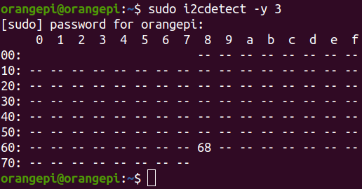

Then you can run the ds1307.py test program in examples to read the RTC time
Note that the x in i2c-x in the following command needs to be replaced with the serial number of the device node corresponding to the i2c bus.
root@orangepi:~/wiringOP-Python# cd examples
root@orangepi:~/wiringOP-Python/examples# python3 ds1307.py --device \
"/dev/i2c-x"
Thu 2022-06-16 04:35:46
Thu 2022-06-16 04:35:47
Thu 2022-06-16 04:35:48
^C
exit
40pin UART test
- As can be seen from the table below, the available uarts are uart2, uart3, uart4 and uart5. Please note that uart0 is set as a debugging serial port by default. Please do not use uart0 as a normal serial port.
GPIO NO. GPIO Function Pin 3.3V 1 264 PI8 TWI1-SDA 3 263 PI7 TWI1-SCL 5 269 PI13 PWM3/UART4_TX 7 GND 9 226 PH2 UART5_TX 11 227 PH3 UART5_RX 13 261 PI5 TWI0_SCL/UART2_TX 15 3.3V 17 231 PH7 SPI1_MOSI 19 232 PH8 SPI1_MISO 21 230 PH6 SPI1_CLK 23 GND 25 266 PI10 TWI2-SDA/UART3_RX 27 256 PI0 29 271 PI15 31 268 PI12 PWM2 33 258 PI2 35 272 PI16 37 GND 39
| Pin | Function | GPIO | GPIO NO. |
| 2 | 5V | ||
| 4 | 5V | ||
| 6 | GND | ||
| 8 | UART0_TX | PH0 | 224 |
| 10 | UART0_RX | PH1 | 225 |
| 12 | PI1 | 257 | |
| 14 | GND | ||
| 16 | PWM4/UART4_RX | PI14 | 270 |
| 18 | PH4 | 228 | |
| 20 | GND | ||
| 22 | TWI0_SDA/UART2_RX | PI6 | 262 |
| 24 | SPI1_CS0 | PH5 | 229 |
| 26 | SPI1_CS1 | PH9 | 233 |
| 28 | TWI2-SCL/UART3_TX | PI9 | 265 |
| 30 | GND | ||
| 32 | PWM1 | PI11 | 267 |
| 34 | GND | ||
| 36 | PC12 | 76 | |
| 38 | PI4 | 260 | |
| 40 | PI3 | 259 |
In Linux systems, uart is turned off by default and needs to be turned on manually before it can be used. The opening steps are as follows::
First run orangepi-config. Ordinary users remember to add sudo permissions.
orangepi@orangepi:~$ sudo orangepi-config
Then select System
Then select Hardware
Then use the keyboard's arrow keys to locate the position shown in the picture below, and then use the space to select the serial port you want to open.
Multiplexing function in 40pin Corresponding dtbo configuration 40pin - uart2 pi-uart2 40pin - uart3 pi-uart3 40pin - uart4 pi-uart4 40pin - uart5 ph-uart5
Then select <Save> to save
Then select <Back>
Then select <Reboot> to restart the system to make the configuration take effect.
After entering the Linux system, first confirm whether there is a uart5 device node under /dev
注意, linux5.4系统为/dev/ttyASx.
orangepi@orangepi:~$ ls /dev/ttyS*
/dev/ttySx
Then start testing the uart interface. First use Dupont wire to short-circuit the rx and tx pins of the uart interface to be tested.
Use the gpio command in wiringOP to test the loopback function of the serial port as shown below. If you can see the following print, it means the serial port communication is normal.
Note that the last x in the gpio serial /dev/ttySx command needs to be replaced with the serial number of the corresponding uart device node.
orangepi@orangepi:~$ gpio serial /dev/ttySx # linux-6.1 test command
orangepi@orangepi:~$ gpio serial /dev/ttyASx # linux-5.4 test command
Out: 0: -> 0
Out: 1: -> 1
Out: 2: -> 2
Out: 3: -> 3^C
Finally, you can run the serialTest.py program in examples to test the loopback function of the serial port. If you can see the following print, it means that the serial port loopback test is normal.
Note that the x in /dev/ttySx or /dev/ttyASx in the command needs to be replaced with the serial number of the corresponding uart device node.
root@orangepi:~/wiringOP-Python# cd examples
root@orangepi:~/wiringOP-Python/examples# python3 serialTest.py --device "/dev/ttySx" # linux6.1 use
root@orangepi:~/wiringOP-Python/examples# python3 serialTest.py --device "/dev/ttyASx" # linux5.4 use
Out: 0: -> 0
Out: 1: -> 1
Out: 2: -> 2
Out: 3: -> 3
Out: 4:^C
exit
Hardware watchdog test
The watchdog_test program is pre-installed in the Linux system released by Orange Pi and can be tested directly.
The method to run the watchdog_test program is as follows:
The second parameter 10 represents the counting time of the watchdog. If the dog is not fed within this time, the system will restart.
We can feed the dog by pressing any key on the keyboard (except ESC). After feeding the dog, the program will print a line "keep alive" to indicate that the dog feeding is successful.
orangepi@orangepi:~$ sudo watchdog_test 10
open success
options is 33152,identity is sunxi-wdt
put_usr return,if 0,success:0
The old reset time is: 16
return ENOTTY,if -1,success:0
return ENOTTY,if -1,success:0
put_user return,if 0,success:0
put_usr return,if 0,success:0
keep alive
keep alive
keep alive
Check the chipid of H618 chip
The command to view the H618 chip chipid is as follows. The chipid of each chip is different, so you can use chipid to distinguish multiple development boards.
|
orangepi@orangepi:~$ cat /sys/class/sunxi_info/sys_info | grep "chipid" sunxi_chipid : 338020004c0048080147478824681ed1 |
How to compile and install Python source code
|
If the Python version in the Ubuntu or Debian system software repository you are using does not meet the development requirements and you want to use the latest version of Python, you can use the following method to download the Python source code package to compile and install the latest version of Python. The following demonstration is to compile and install the latest version of Python 3.9. If you want to compile and install other versions of Python, the method is the same (you need to download the source code corresponding to the Python you want to install). |
First install the dependency packages needed to compile Python
orangepi@orangepi:~$ sudo apt-get update
orangepi@orangepi:~$ sudo apt-get install -y build-essential zlib1g-dev \
libncurses5-dev libgdbm-dev libnss3-dev libssl-dev libsqlite3-dev \
libreadline-dev libffi-dev curl libbz2-dev
Then download the latest version of Python3.9 source code and unzip it
orangepi@orangepi:~$ wget \
https://www.python.org/ftp/python/3.9.10/Python-3.9.10.tgz
orangepi@orangepi:~$ tar xvf Python-3.9.10.tgz
Then run the configuration command
orangepi@orangepi:~$ cd Python-3.9.10
orangepi@orangepi:~$ ./configure --enable-optimizations
Then compile and install Python3.9. The compilation time takes about half an hour.
orangepi@orangepi:~$ make -j4
orangepi@orangepi:~$ sudo make altinstall
After installation, you can use the following command to check the version number of the Python you just installed.
orangepi@orangepi:~$ python3.9 --version
Python 3.9.10
Then update pip
orangepi@orangepi:~$ /usr/local/bin/python3.9 -m pip install --upgrade pip
How to replace pip source in Python
|
The default source used by Linux system pip is the official source of Python. However, accessing the official source of Python in China is very slow, and the installation of Python software packages often fails due to network reasons. So when using pip to install the Python library, please remember to change the pip source. |
First install python3-pip
orangepi@orangepi:~$ sudo apt-get update
orangepi@orangepi:~$ sudo apt-get install -y python3-pip
How to permanently change the pip source under Linux
First create a new ~/.pip directory, then add the pip.conf configuration file, and set the pip source in it to Tsinghua source.
orangepi@orangepi:~$ mkdir -p ~/.pip
orangepi@orangepi:~$ cat <<EOF > ~/.pip/pip.conf
[global]
timeout = 6000
index-url = https://pypi.tuna.tsinghua.edu.cn/simple
trusted-host = pypi.tuna.tsinghua.edu.cn
EOF
Then use pip3 to install the Python library very quickly
How to temporarily change the pip source under Linux, where <packagename> needs to be replaced with a specific package name
orangepi@orangepi:~$ pip3 install <packagename> -i \
https://pypi.tuna.tsinghua.edu.cn/simple --trusted-host pypi.tuna.tsinghua.edu.cn
How to install Docker
The Linux image provided by Orange Pi has Docker pre-installed, but the Docker service is not turned on by default. Use the enable_docker.sh script to enable the docker service, and then you can start using the docker command, and the docker service will be automatically started the next time you start the system.
|
orangepi@orangepi:~$ enable_docker.sh |
You can use the following command to test docker. If hello-world can be run, docker can be used normally.
|
orangepi@orangepi:~$ docker run hello-world Unable to find image 'hello-world:latest' locally latest: Pulling from library/hello-world 256ab8fe8778: Pull complete Digest: sha256:7f0a9f93b4aa3022c3a4c147a449ef11e0941a1fd0bf4a8e6c9408b2600777c5 Status: Downloaded newer image for hello-world:latest
This message shows that your installation appears to be working correctly. .…. |
When using the docker command, if you are prompted for permission denied, please add the current user to the docker user group so that you can run the docker command without sudo.
|
orangepi@orangepi:~$ sudo usermod -aG docker $USER |
|
Note: You need to log out and log in again to the system to take effect. You can also restart the system. |
How to install Home Assistant
|
Note that this article will only provide methods for installing Home Assistant in Ubuntu or Debian systems. For detailed usage of Home Assistant, please refer to the official documentation or corresponding books. |
Installation via docker
First, please install docker and ensure that docker can run normally. For the installation steps of docker, please refer to the instructions in the How to Install Docker section.
Then you can search for the docker image of Home Assistant
orangepi@orangepi:~$ docker search homeassistant
Then use the following command to download the Docker image of Home Assistant to your local computer. The image size is about 1GB, and the download time will be relatively long. Please be patient and wait for the download to complete.
orangepi@orangepi:~$ docker pull homeassistant/home-assistant
Using default tag: latest
latest: Pulling from homeassistant/home-assistant
be307f383ecc: Downloading
5fbc4c07ac88: Download complete
...... (Omit some output)
3cc6a1510c9f: Pull complete
7a4e4d5b979f: Pull complete
Digest: sha256:81d381f5008c082a37da97d8b08dd8b358dae7ecf49e62ce3ef1eeaefc4381bb
Status: Downloaded newer image for homeassistant/home-assistant:latest
docker.io/homeassistant/home-assistant:latest
Then you can use the following command to view the docker image of Home Assistant you just downloaded
orangepi@orangepi:~$ docker images homeassistant/home-assistant
REPOSITORY TAG IMAGE ID CREATED SIZE
homeassistant/home-assistant latest bfa0ab9e1cf5 2 months ago 1.17GB
At this point you can run the Home Assistant docker container
orangepi@orangepi:~$ docker run -d \
--name homeassistant \
--privileged \
--restart=unless-stopped \
-e TZ=Asia/Shanghai \
-v /home/orangepi/home-assistant:/config \
--network=host \
homeassistant/home-assistant:latest
Then enter【the IP address of the development board: 8123】in the browser to see the Home Assistant interface
It takes a while for the Home Assistant container to start. If the interface below does not display normally, please wait a few seconds before refreshing it. If the following interface is not displayed normally after waiting for more than a minute, it means there is a problem with the Home Assistant installation. At this time, you need to check whether there is a problem with the previous installation and setting process.

Then enter your name, username and password and click Create Account
Then follow the interface prompts to set according to your own preferences, and then click Next
Then click Next
Then click Finish
The main interface finally displayed by Home Assistant is as shown below
Method to stop Home Assistant container
The command to view the docker container is as follows
orangepi@orangepi:~$ docker ps -a
The command to stop the Home Assistant container is as follows
orangepi@orangepi:~$ docker stop homeassistant
The command to delete the Home Assistant container is as follows
orangepi@orangepi:~$ docker rm homeassistant


Installation via python
|
Before installation, please change the source of pip to a domestic source to speed up the installation of Python packages. For the configuration method, see the instructions in the section "How to Change the Pip Source of Python" |
First install dependency packages
orangepi@orangepi:~$ sudo apt-get update
orangepi@orangepi:~$ sudo apt-get install -y python3 python3-dev python3-venv \
python3-pip libffi-dev libssl-dev libjpeg-dev zlib1g-dev autoconf build-essential \
libopenjp2-7 libtiff5 libturbojpeg0-dev tzdata
If it is debian12, please use the following command:
orangepi@orangepi:~$ sudo apt-get update
orangepi@orangepi:~$ sudo apt-get install -y python3 python3-dev python3-venv \
python3-pip libffi-dev libssl-dev libjpeg-dev zlib1g-dev autoconf build-essential \
libopenjp2-7 libturbojpeg0-dev tzdata
Then you need to compile and install Python3.9. For the method, please refer to the Python source code compilation and installation method section.
The default Python version of Debian Bullseye is Python3.9, so there is no need to compile and install it.
The default Python version of Ubuntu Jammy is Python3.10, so there is no need to compile and install it.
The default Python version of Debian Bookworm is Python3.11, so there is no need to compile and install it.
Then create a Python virtual environment
Debian Bookworm is python3.11, please remember to replace the corresponding command.
orangepi@orangepi:~$ sudo mkdir /srv/homeassistant
orangepi@orangepi:~$ sudo chown orangepi:orangepi /srv/homeassistant
orangepi@orangepi:~$ cd /srv/homeassistant
orangepi@orangepi:~$ python3.9 -m venv .
orangepi@orangepi:~$ source bin/activate
(homeassistant) orangepi@orangepi:/srv/homeassistant$
Then install the required Python packages
(homeassistant) orangepi@orangepi:/srv/homeassistant$ python3 -m pip install wheel
Then you can install Home Assistant Core
(homeassistant) orangepi@orangepi:/srv/homeassistant$ pip3 install homeassistant
Then enter the following command to run Home Assistant Core
(homeassistant) orangepi@orangepi:/srv/homeassistant$ hass
Then enter【development board IP address: 8123】 in the browser to see the Home Assistant interface
When you run the hass command for the first time, some libraries and dependency packages necessary for operation will be downloaded, installed and cached. This process may take several minutes. Note that you cannot see the Home Assistant interface in the browser at this time. Please wait for a while and then refresh it.
OpenCV installation method
Use apt to install OpenCV
The installation command is as follows
orangepi@orangepi:~$ sudo apt-get update
orangepi@orangepi:~$ sudo apt-get install -y libopencv-dev python3-opencv
Then use the following command to print the version number of OpenCV. The output is normal, indicating that the OpenCV installation is successful.
The version of OpenCV in Ubuntu22.04 is as follows:
orangepi@orangepi:~$ python3 -c "import cv2; print(cv2.__version__)"
4.5.4
The version of OpenCV in Ubuntu20.04 is as follows:
orangepi@orangepi:~$ python3 -c "import cv2; print(cv2.__version__)"
4.2.0
The version of OpenCV in Debian11 is as follows:
orangepi@orangepi:~$ python3 -c "import cv2; print(cv2.__version__)"
4.5.1
The version of OpenCV in Debian12 is as follows:
orangepi@orangepi:~$ python3 -c "import cv2; print(cv2.__version__)"
4.6.0
Set up the Chinese environment and install the Chinese input method
|
Note, before installing the Chinese input method, please make sure that the Linux system used by the development board is a desktop version. |
Debian system installation method
First set the default locale to Chinese
Enter the following command to start configuring locale
orangepi@orangepi:~$ sudo dpkg-reconfigure locales
Then select zh_CN.UTF-8 UTF-8 in the pop-up interface (use the up and down keys on the keyboard to move up and down, use the space bar to select, and finally use the Tab key to move the cursor to <OK>, and then return Car can be used)
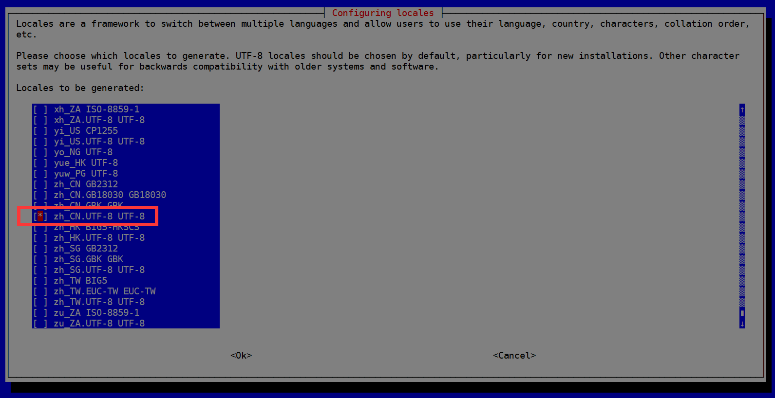
Then set the default locale to zh_CN.UTF-8
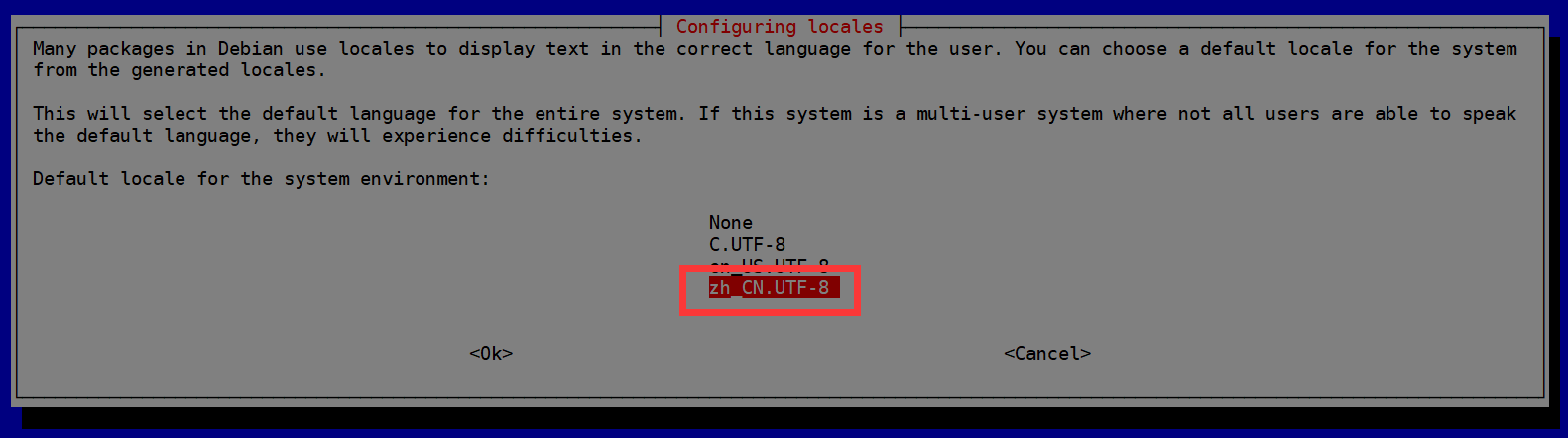
After exiting the interface, the locale setting will begin. The output displayed on the command line is as follows:
orangepi@orangepi:~$ sudo dpkg-reconfigure locales
Generating locales (this might take a while)...
en_US.UTF-8... done
zh_CN.UTF-8... done
Generation complete.
Then open Input Method

Then select OK
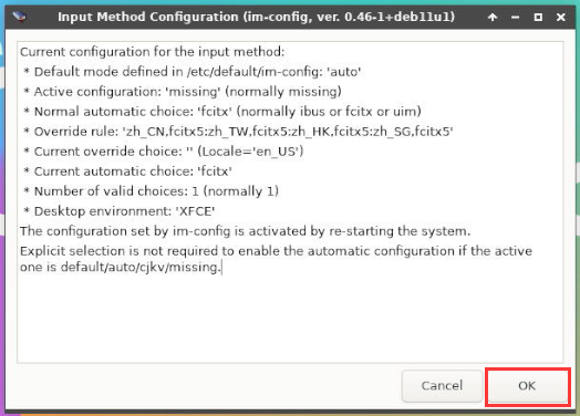
Then select Yes
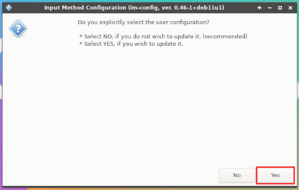
Then select fcitx
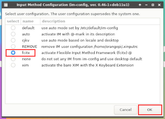
Then select OK
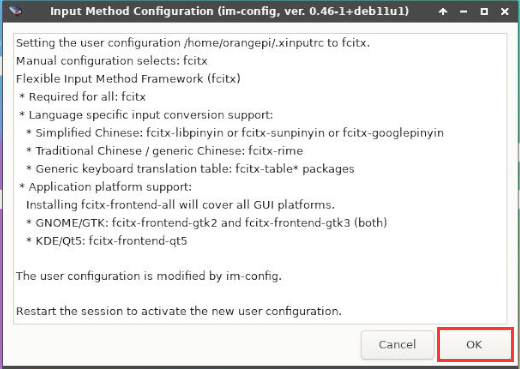
Then restart the Linux system to make the configuration take effect.
Then open Fcitx configuration

Then click the + sign as shown in the picture below
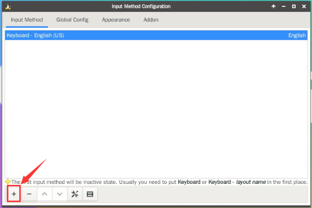
Then search Google Pinyin and click OK
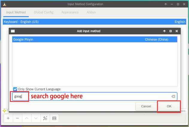
Then put Google Pinyin on top
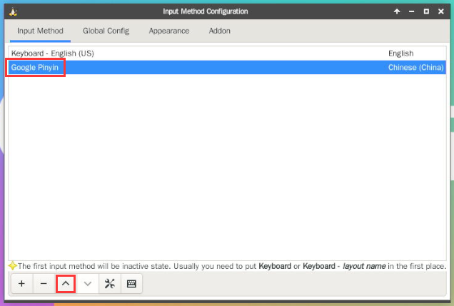
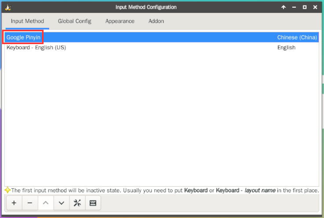
Then open the Geany editor to test the Chinese input method

The Chinese input method test is as follows
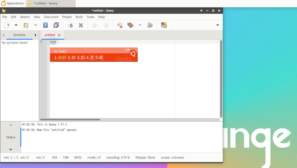
You can switch between Chinese and English input methods through the Ctrl+Space shortcut key
If you need the entire system to be displayed in Chinese, you can set all variables in /etc/default/locale to zh_CN.UTF-8
orangepi@orangepi:~$ sudo vim /etc/default/locale
# File generated by update-locale
LC_MESSAGES=zh_CN.UTF-8
LANG=zh_CN.UTF-8
LANGUAGE=zh_CN.UTF-8
Then restart the system and you will see that the system is displayed in Chinese.


Installation method of Ubuntu 20.04 system
First open Language Support

Then find the Chinese (China) option
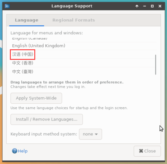
Then please use the left button of the mouse to select Chinese (China) and hold it down, then drag it up to the starting position. After dragging, the display will be as shown below:
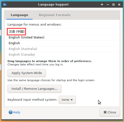


|
Note that this step is not easy to drag, please be patient and try it a few times. |
Then select Apply System-Wide to apply the Chinese settings to the entire system
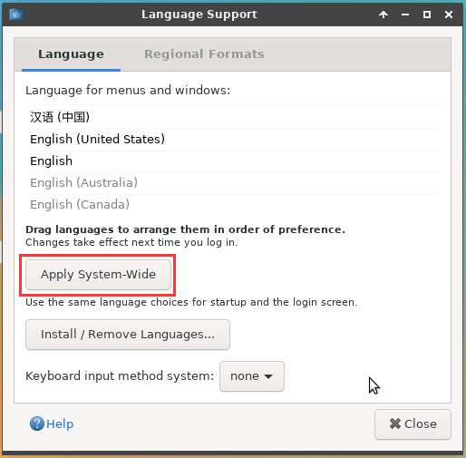
Then set the Keyboard input method system system to fcitx
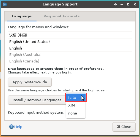
Then restart the Linux system to make the configuration take effect
After re-entering the system, please select Do not ask me again in the following interface, and then please decide according to your own preferences whether the standard folder should also be updated to Chinese
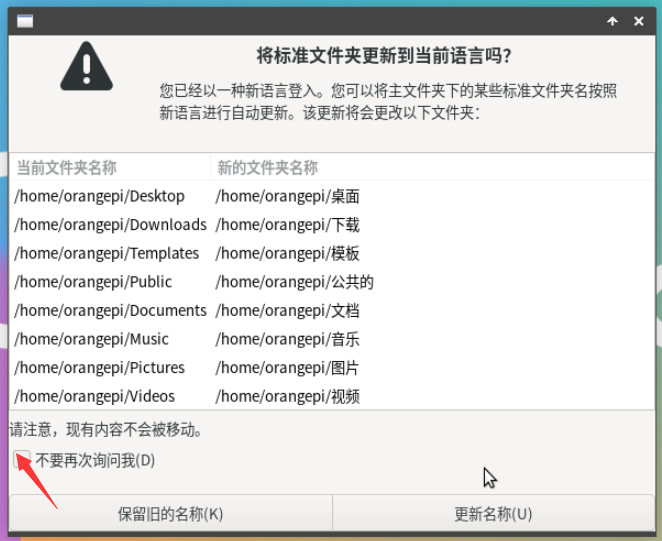
Then you can see that the desktop is displayed in Chinese

Then we can open Geany to test the Chinese input method. The opening method is as shown in the figure below

After opening Geany, the English input method is still the default. We can switch to the Chinese input method through the Ctrl+Space shortcut key, and then we can input Chinese.
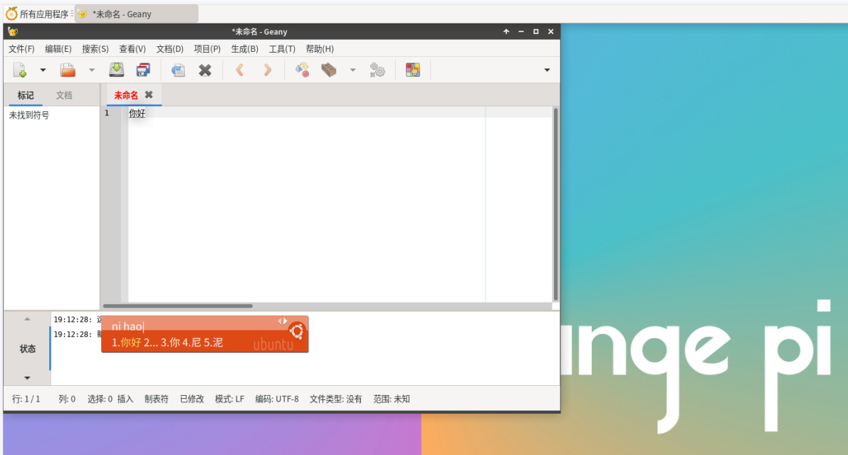


Installation method of Ubuntu 22.04 system
First open Language Support
Then find the Chinese (China) option
Then please use the left button of the mouse to select Chinese (China) and hold it down, then drag it up to the starting position. After dragging, the display will be as shown below:


|
Note that this step is not easy to drag, please be patient and try it a few times. |
Then select Apply System-Wide to apply the Chinese settings to the entire system
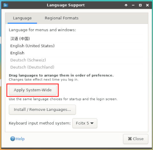
Then restart the Linux system to make the configuration take effect
After re-entering the system, please select Do not ask me again in the following interface, and then please decide whether the standard folder should also be updated to Chinese according to your own preferences.
Then you can see that the desktop is displayed in Chinese
Then open the Fcitx5 configuration program

Then choose to use Pinyin input method
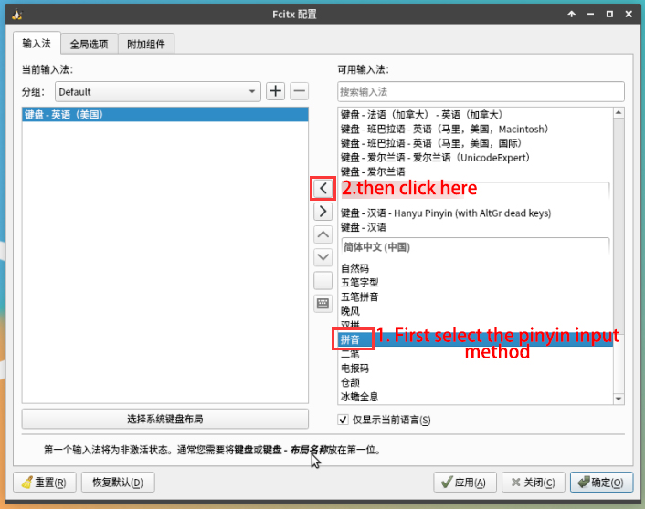
The interface after selection is as shown below, then click OK
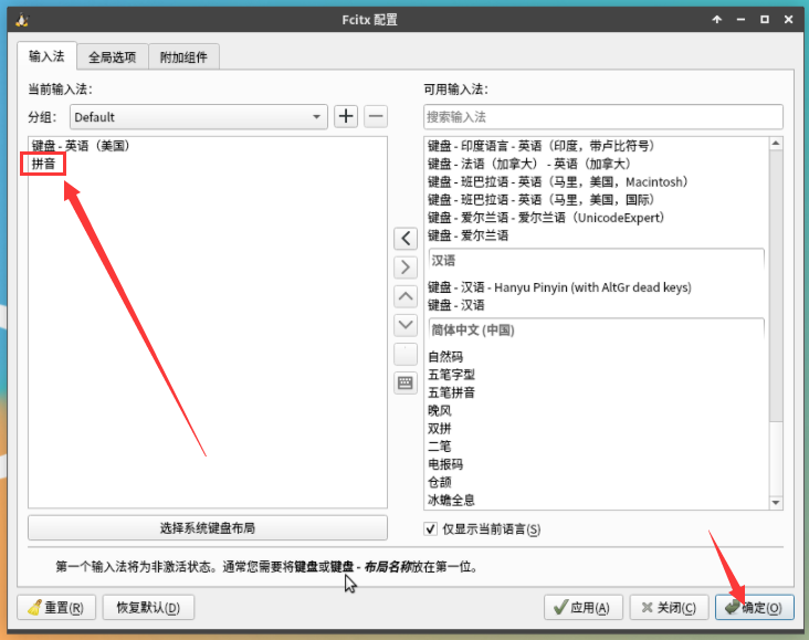
Then we can open Geany to test the Chinese input method. The opening method is as shown in the figure below
After opening Geany, the English input method is still the default. We can switch to the Chinese input method through the Ctrl+Space shortcut key, and then we can enter Chinese.
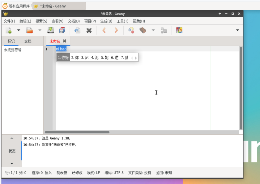


How to remotely log in to the Linux system desktop
Remote login using NoMachine
|
Please ensure that the Ubuntu or Debian system installed on the development board is a desktop version of the system. In addition, NoMachine also provides detailed usage documentation. It is strongly recommended to read this document thoroughly to become familiar with the use of NoMachine. The document link is as follows: |
|
NoMachine supports Windows, Mac, Linux, iOS and Android platforms, so we can remotely log in and control the Orange Pi development board through NoMachine on a variety of devices. The following demonstrates how to remotely log in to the Linux system desktop of the Orange Pi development board through NoMachine in Windows. For installation methods on other platforms, please refer to NoMachine's official documentation. |
|
Before operating, please make sure that the Windwos computer and the development board are in the same LAN, and that you can log in to the Ubuntu or Debian system of the development board through ssh normally. |
First download the installation package of the NoMachine software Linux arm64 deb version, and then install it into the Linux system of the development board
- Since H618 is an ARMv8 architecture SOC and the system we use is Ubuntu or Debian, we need to download the NoMachine for ARM ARMv8 DEB installation package. The download link is as follows:
Note that this download link may change, please look for the Armv8/Arm64 version of the deb package.
In addition, you can also download the NoMachine installation package from the official tool.

First enter the remote login software-NoMachine folder

Then download the arm64 version of the deb installation package
Then upload the downloaded nomachine_x.x.x_x_arm64.deb to the Linux system of the development board
Then use the following command to install NoMachine in the Linux system of the development board
orangepi@orangepi:~$ sudo dpkg -i nomachine_x.x.x_x_arm64_arm64.deb


- Then download the installation package of the Windows version of the NoMachine software. The download address is as follows
|
Note that this download link may change. |

Then install NoMachine in Windows. Please restart your computer after installation.
Then open NoMachine in Window

After NoMachine is started, it will automatically scan other devices with NoMachine installed on the LAN. After entering the main interface of NoMachine, you can see that the development board is already in the list of connectable devices, and then click on the location shown in the red box in the picture below You can now log in to the Linux system desktop of the development board.
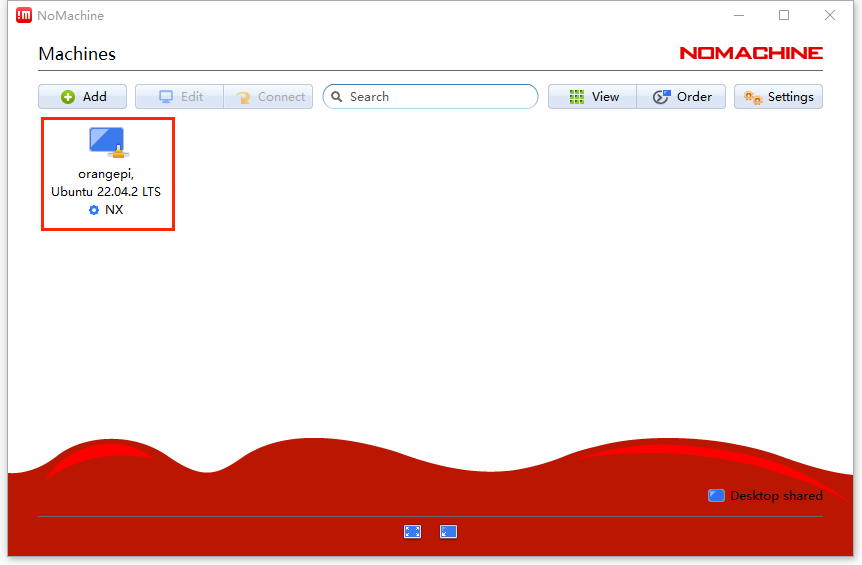
Then click OK
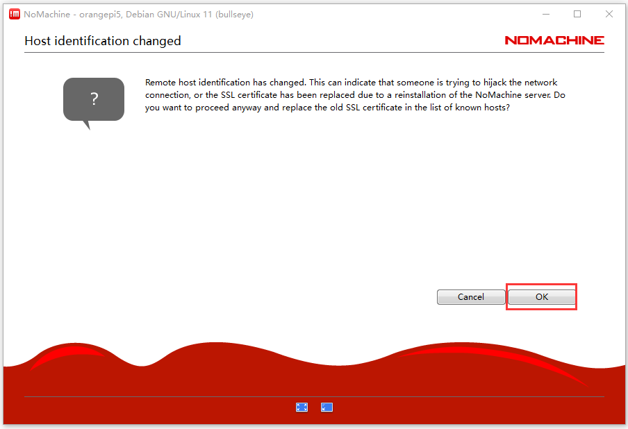
Then enter the username and password of the development board Linux system in the corresponding positions in the figure below, and then click OK to start logging in.
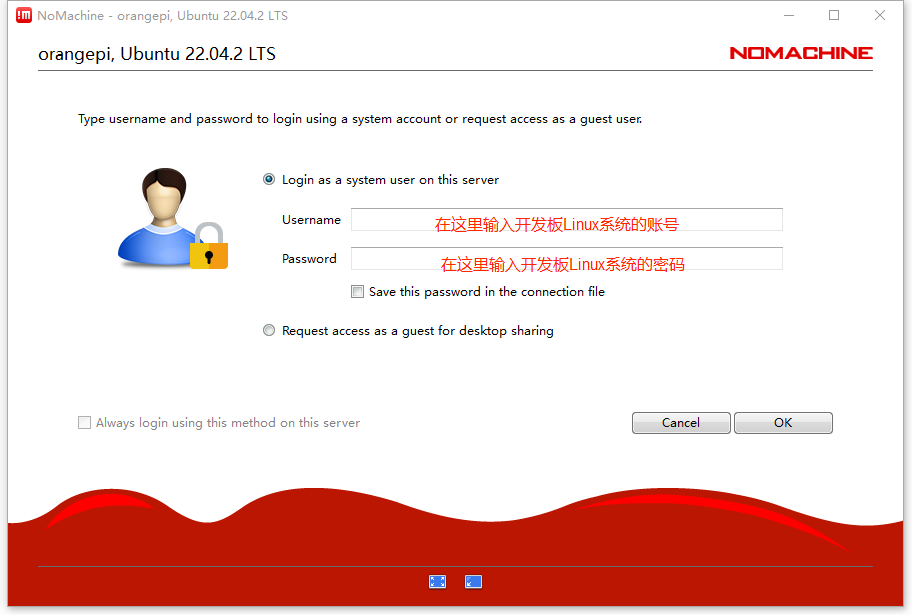
Then click OK in the next interface.
Finally you can see the desktop of the development board Linux system


Remote login using VNC
|
Before operating, please make sure that the Windwos computer and the development board are in the same LAN, and that you can log in to the Ubuntu or Debian system of the development board through ssh normally. There are many problems with VNC testing in Ubuntu20.04, please do not use this method. |
First run the set_vnc.sh script to set up vnc, remember to add sudo permissions
orangepi@orangepi:~$ sudo set_vnc.sh
You will require a password to access your desktops.
Password: #Set the vnc password here, 8 characters
Verify: #Set the vnc password here, 8 characters
Would you like to enter a view-only password (y/n)? n
xauth: file /root/.Xauthority does not exist
New 'X' desktop is orangepi:1
Creating default startup script /root/.vnc/xstartup
Starting applications specified in /root/.vnc/xstartup
Log file is /root/.vnc/orangepi:1.log
Killing Xtightvnc process ID 3047
New 'X' desktop is orangepi:1
Starting applications specified in /root/.vnc/xstartup
Log file is /root/.vnc/orangepi:1.log
The steps to use MobaXterm software to connect to the development board Linux system desktop are as follows:
- First click Session, then select VNC, then fill in the IP address and port of the development board, and finally click OK to confirm.
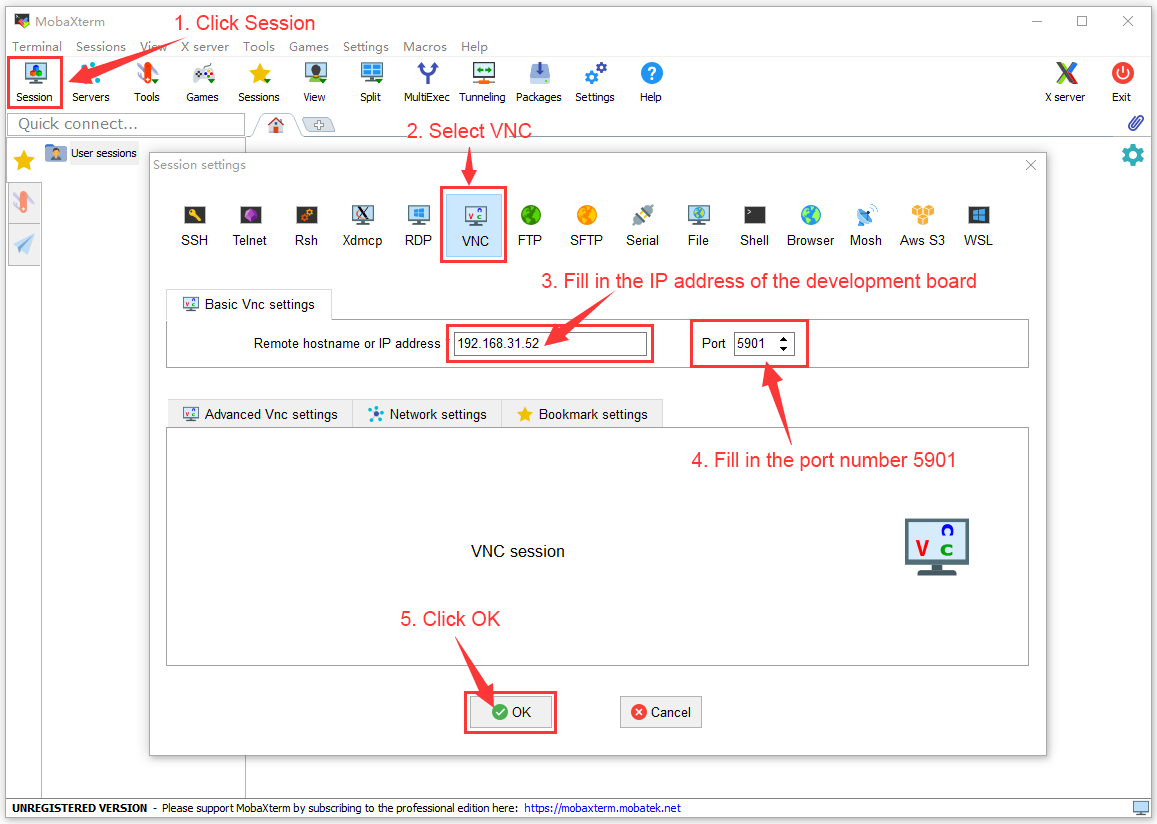
Then enter the VNC password set earlier
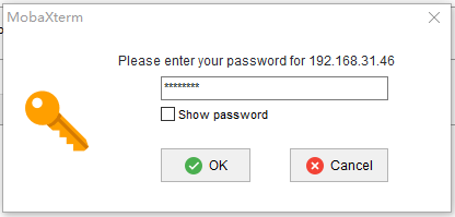
After successful login, the interface is displayed as shown below, and then you can remotely operate the desktop of the development board Linux system.
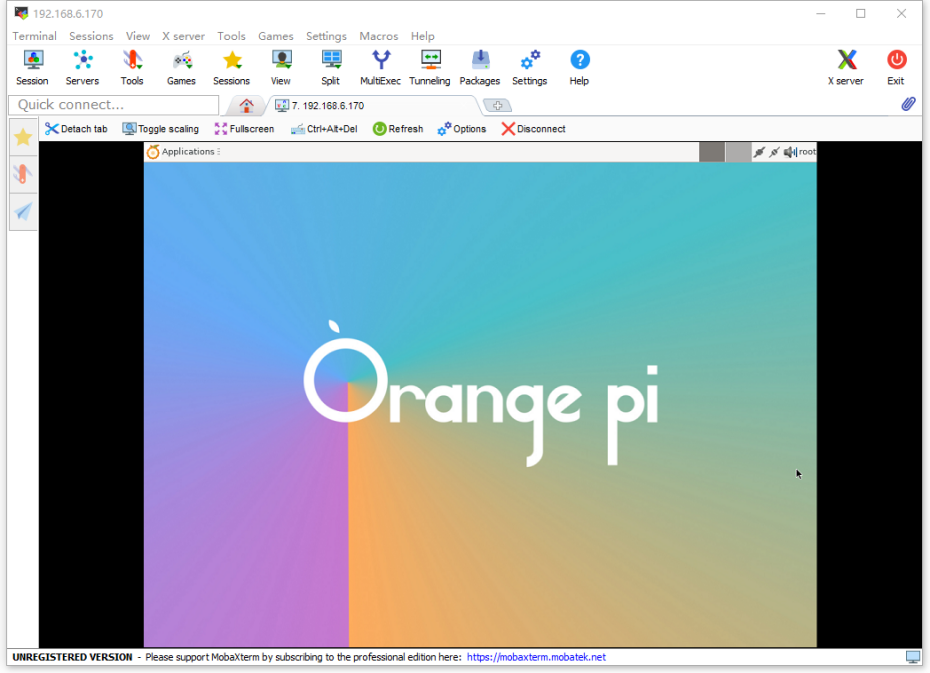


QT installation method
Use the following script to install QT5 and QT Creator
orangepi@orangepi:~$ install_qt.sh
After installation, the QT version number will be automatically printed.
The qt version that comes with Ubuntu20.04 is 5.12.8
orangepi@orangepi:~$ install_qt.sh
......
QMake version 3.1
Using Qt version 5.12.8 in /usr/lib/aarch64-linux-gnu
The QT version that comes with Ubuntu22.04 is 5.15.3
orangepi@orangepi:~$ install_qt.sh
......
QMake version 3.1
Using Qt version 5.15.3 in /usr/lib/aarch64-linux-gnu
The QT version that comes with Debian11 is 5.15.2
orangepi@orangepi:~$ install_qt.sh
......
QMake version 3.1
Using Qt version 5.15.2 in /usr/lib/aarch64-linux-gnu
The QT version that comes with Debian12 is 5.15.8
orangepi@orangepi:~$ install_qt.sh
......
QMake version 3.1
Using Qt version 5.15.8 in /usr/lib/aarch64-linux-gnu
Then you can see the QT Creator startup icon in Applications

You can also use the following command to open QT Creator
orangepi@orangepi:~$ qtcreator
The interface after QT Creator is opened is as follows
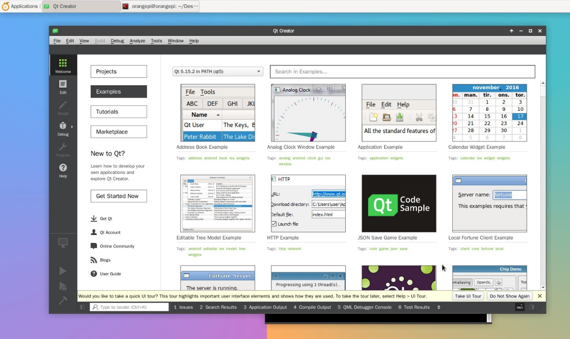
The version of QT Creator is as follows
The default version of QT Creator in Ubuntu20.04 is as follows
The default version of QT Creator in Ubuntu22.04 is as follows
The default version of QT Creator in Debian11 is as follows
The default version of QT Creator in Debian12 is as follows
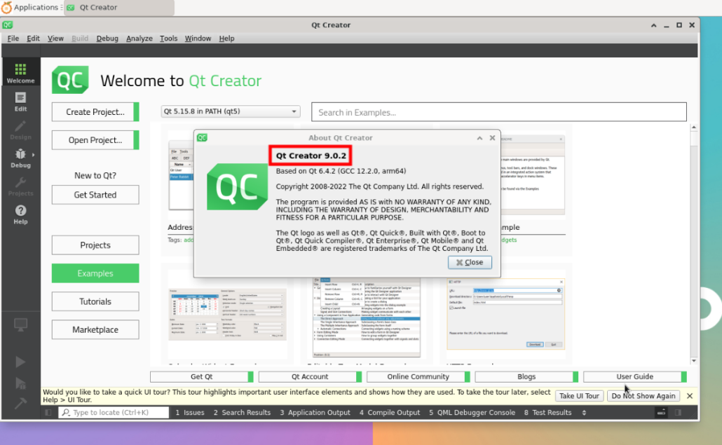
Then set up QT
First open Help->About Plugins....
Then remove the check mark of ClangCodeModel
After setting up, you need to restart QT Creator
Then make sure the GCC compiler used by QT Creator. If the default is Clang, please change it to GCC.
Debian12 please skip this step.
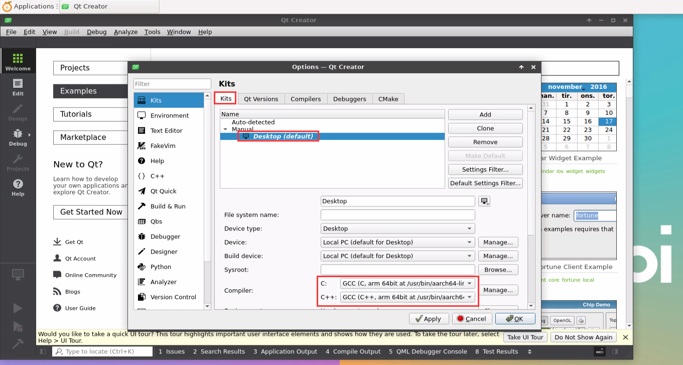
Then you can open a sample code
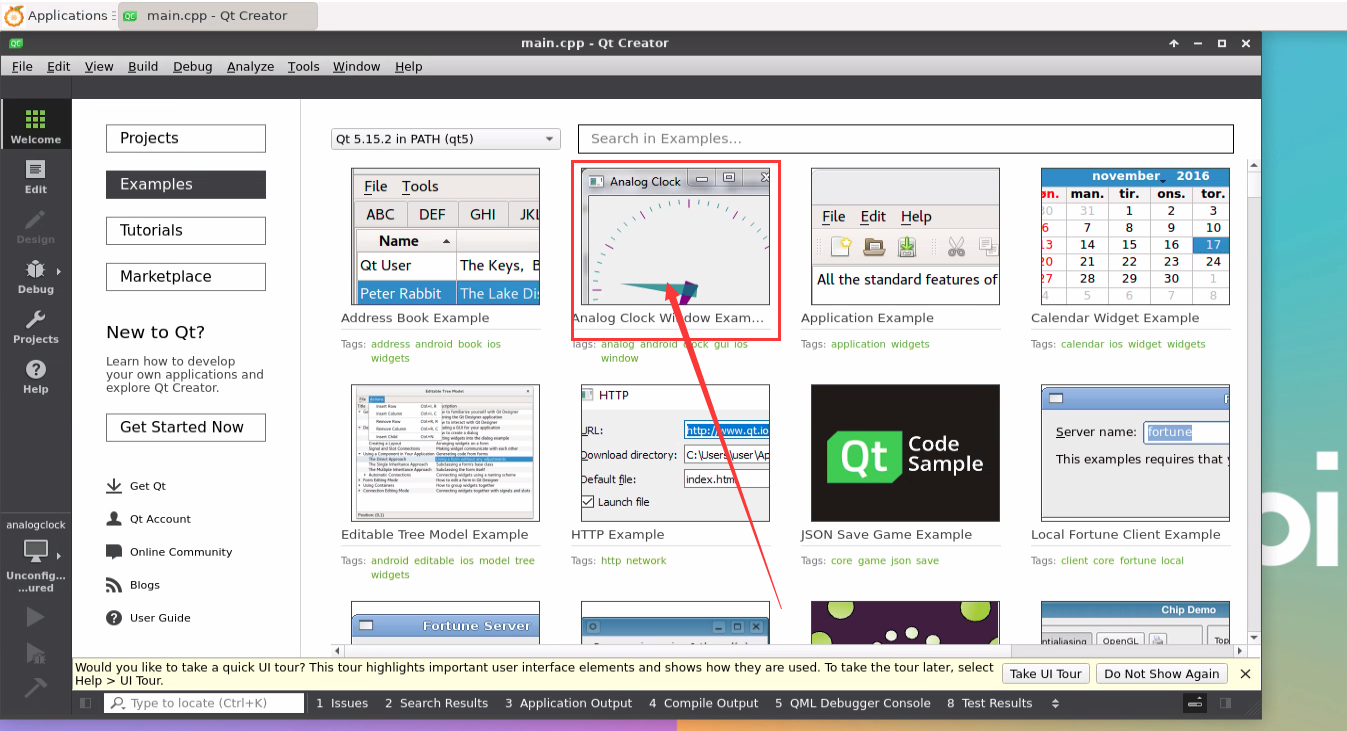
After clicking on the sample code, the corresponding instruction document will automatically open. You can read the instructions carefully.
Then click Configure Project
Then click the green triangle in the lower left corner to compile and run the sample code
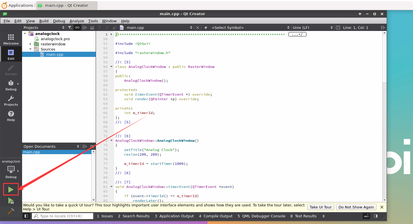
After waiting for a period of time, the interface shown in the figure below will pop up, which means that QT can compile and run normally.
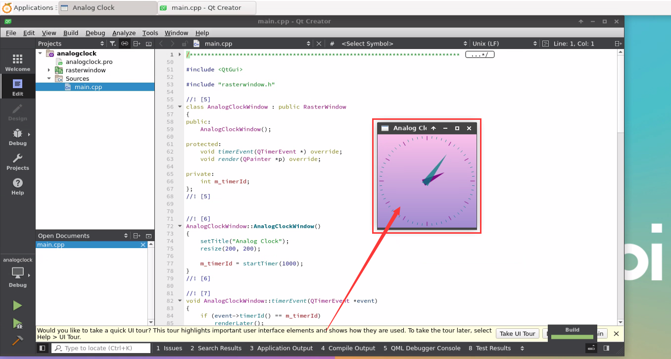
References
https://wiki.qt.io/Install_Qt_5_on_Ubuntu


ROS installation method
How to install ROS 1 Noetic on Ubuntu20.04
- The currently active version of ROS 1 is as follows, the recommended version is Noetic Ninjemys


The link to the official installation documentation of ROS 1 Noetic Ninjemys is as follows:
In the official installation documentation of ROS Noetic Ninjemys, Ubuntu recommends using Ubuntu20.04, so please ensure that the system used by the development board is Ubuntu20.04 desktop system.
http://wiki.ros.org/noetic/Installation
Then use the script below to install ros1
orangepi@orangepi:~$ install_ros.sh ros1
Before using the ROS tool, you first need to initialize rosdep. Then when compiling the source code, you can quickly install some system dependencies and some core components in ROS.
- The read operation timed out
- rosdep update

|
Note that when running the following command, you need to ensure that the development board can access github normally, otherwise an error will be reported due to network problems.
Hit https://raw.githubusercontent.com/ros/rosdistro/master/rosdep/base.yaml ERROR: error loading sources list: |
|
orangepi@orangepi:~$ source /opt/ros/noetic/setup.bash orangepi@orangepi:~$ sudo rosdep init Wrote /etc/ros/rosdep/sources.list.d/20-default.list Recommended: please run
orangepi@orangepi:~$ rosdep update reading in sources list data from /etc/ros/rosdep/sources.list.d Hit https://raw.githubusercontent.com/ros/rosdistro/master/rosdep/osx-homebrew.yaml Hit https://raw.githubusercontent.com/ros/rosdistro/master/rosdep/base.yaml Hit https://raw.githubusercontent.com/ros/rosdistro/master/rosdep/python.yaml Hit https://raw.githubusercontent.com/ros/rosdistro/master/rosdep/ruby.yaml Hit https://raw.githubusercontent.com/ros/rosdistro/master/releases/fuerte.yaml Query rosdistro index https://raw.githubusercontent.com/ros/rosdistro/master/index-v4.yaml Skip end-of-life distro "ardent" Skip end-of-life distro "bouncy" Skip end-of-life distro "crystal" Skip end-of-life distro "dashing" Skip end-of-life distro "eloquent" Add distro "foxy" Add distro "galactic" Skip end-of-life distro "groovy" Add distro "humble" Skip end-of-life distro "hydro" Skip end-of-life distro "indigo" Skip end-of-life distro "jade" Skip end-of-life distro "kinetic" Skip end-of-life distro "lunar" Add distro "melodic" Add distro "noetic" Add distro "rolling" updated cache in /home/orangepi/.ros/rosdep/sources.cache |
Then open a command line terminal window on the desktop, and then use the test_ros.sh script to start a small turtle routine to test whether ROS can be used normally.
orangepi@orangepi:~$ test_ros.sh
After running the test_ros.sh script, a small turtle as shown in the picture below will pop up.
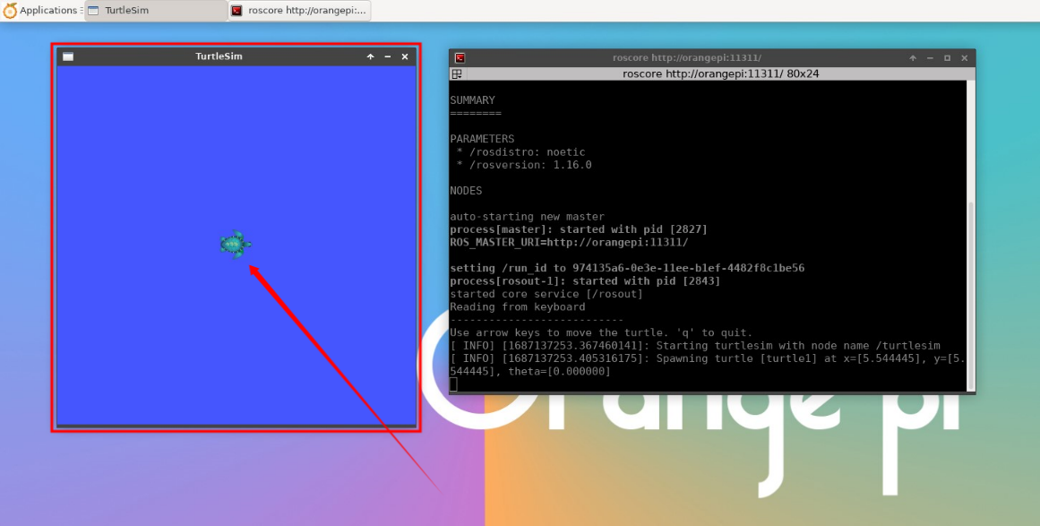
Then please keep the terminal window you just opened at the top


At this time, press the direction keys on the keyboard to control the little turtle to move up, down, left, and right.
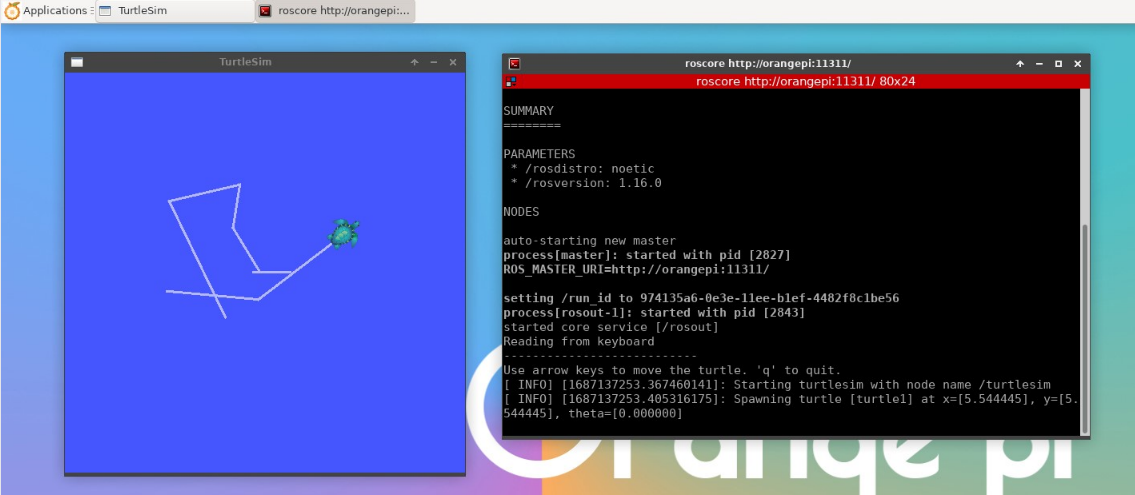

How to install ROS 2 Galactic on Ubuntu20.04
The currently active version of ROS 2 is as follows, the recommended version is Galactic Geochelone


The link to the official installation documentation of ROS 2 Galactic Geochelone is as follows:
docs.ros.org/en/galactic/Installation.html
http://docs.ros.org/en/galactic/Installation/Ubuntu-Install-Debians.html
In the official installation documentation of ROS 2 Galactic Geochelone, Ubuntu Linux recommends using Ubuntu20.04, so please ensure that the system used by the development board is the Ubuntu20.04 desktop system. There are several ways to install ROS 2. The following demonstrates how to install ROS 2 Galactic Geochelone through Debian packages.
Use the install_ros.sh script to install ros2
orangepi@orangepi:~$ install_ros.sh ros2
The install_ros.sh script will automatically run the ros2 -h command after installing ros2. If you can see the following print, it means that the ros2 installation is complete.
usage: ros2 [-h] Call `ros2 <command> -h` for more detailed usage. ...
ros2 is an extensible command-line tool for ROS 2.
optional arguments:
-h, --help show this help message and exit
Commands:
action Various action related sub-commands
bag Various rosbag related sub-commands
component Various component related sub-commands
daemon Various daemon related sub-commands
doctor Check ROS setup and other potential issues
interface Show information about ROS interfaces
launch Run a launch file
lifecycle Various lifecycle related sub-commands
multicast Various multicast related sub-commands
node Various node related sub-commands
param Various param related sub-commands
pkg Various package related sub-commands
run Run a package specific executable
security Various security related sub-commands
service Various service related sub-commands
topic Various topic related sub-commands
wtf Use `wtf` as alias to `doctor`
Call `ros2 <command> -h` for more detailed usage.
Then you can use the test_ros.sh script to test whether ROS 2 is installed successfully. If you can see the following print, it means ROS 2 can run normally.
orangepi@orangepi:~$ test_ros.sh
[INFO] [1671174101.200091527] [talker]: Publishing: 'Hello World: 1'
[INFO] [1671174101.235661048] [listener]: I heard: [Hello World: 1]
[INFO] [1671174102.199572327] [talker]: Publishing: 'Hello World: 2'
[INFO] [1671174102.204196299] [listener]: I heard: [Hello World: 2]
[INFO] [1671174103.199580322] [talker]: Publishing: 'Hello World: 3'
[INFO] [1671174103.204019965] [listener]: I heard: [Hello World: 3]
Run the following command to open rviz2
orangepi@orangepi:~$ source /opt/ros/galactic/setup.bash
orangepi@orangepi:~$ ros2 run rviz2 rviz2
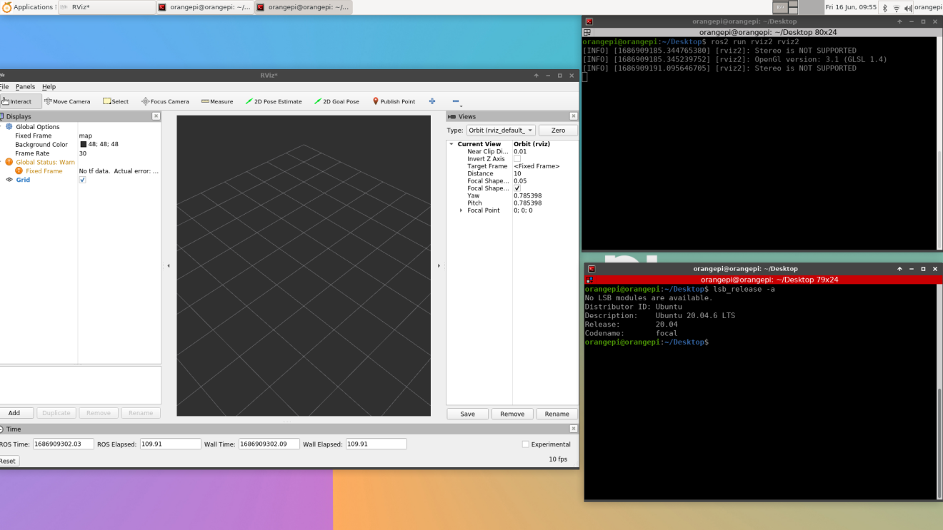
For how to use ROS, please refer to the documentation of ROS 2.


How to install ROS 2 Humble on Ubuntu22.04
Use the install_ros.sh script to install_ros.sh
orangepi@orangepi:~$ install_ros.sh ros2
The install_ros.sh script will automatically run the ros2 -h command after installing ros2. If you can see the following print, it means that the ros2 installation is complete.
usage: ros2 [-h] Call `ros2 <command> -h` for more detailed usage. ...
ros2 is an extensible command-line tool for ROS 2.
optional arguments:
-h, --help show this help message and exit
Commands:
action Various action related sub-commands
bag Various rosbag related sub-commands
component Various component related sub-commands
daemon Various daemon related sub-commands
doctor Check ROS setup and other potential issues
interface Show information about ROS interfaces
launch Run a launch file
lifecycle Various lifecycle related sub-commands
multicast Various multicast related sub-commands
node Various node related sub-commands
param Various param related sub-commands
pkg Various package related sub-commands
run Run a package specific executable
security Various security related sub-commands
service Various service related sub-commands
topic Various topic related sub-commands
wtf Use `wtf` as alias to `doctor`
Call `ros2 <command> -h` for more detailed usage.
Then you can use the test_ros.sh script to test whether ROS 2 is successfully installed. If you can see the following print, it means ROS 2 can run normally.
orangepi@orangepi:~$ test_ros.sh
[INFO] [1671174101.200091527] [talker]: Publishing: 'Hello World: 1'
[INFO] [1671174101.235661048] [listener]: I heard: [Hello World: 1]
[INFO] [1671174102.199572327] [talker]: Publishing: 'Hello World: 2'
[INFO] [1671174102.204196299] [listener]: I heard: [Hello World: 2]
[INFO] [1671174103.199580322] [talker]: Publishing: 'Hello World: 3'
[INFO] [1671174103.204019965] [listener]: I heard: [Hello World: 3]
Run the following command to open rviz2
orangepi@orangepi:~$ source /opt/ros/humble/setup.bash
orangepi@orangepi:~$ ros2 run rviz2 rviz2
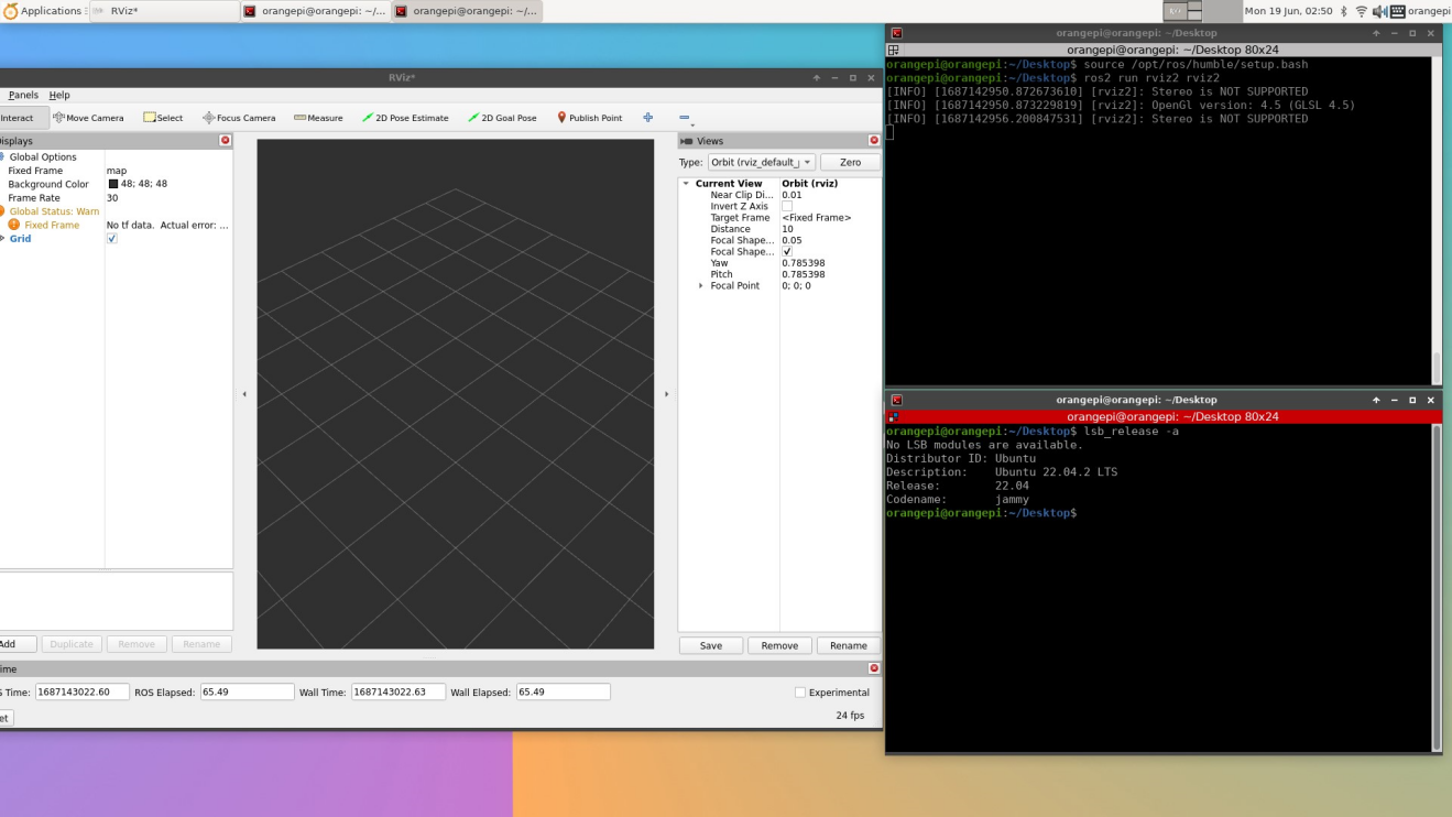
Reference documentation
http://docs.ros.org/en/humble/index.html
http://docs.ros.org/en/humble/Installation/Ubuntu-Install-Debians.html

How to install kernel header files
|
Debian11 system with Linux6.1 kernel will report GCC error when compiling kernel module. So if you want to compile the kernel module, please use Debian12 or Ubuntu22.04. |
The Linux image released by OPi comes with the deb package of the kernel header file by default, and the storage location is /opt/
orangepi@orangepi:~$ ls /opt/linux-headers*
/opt/linux-headers-xxx-sun50iw9_x.x.x_arm64.deb
Use the following command to install the deb package of the kernel header file
orangepi@orangepi:~$ sudo dpkg -i /opt/linux-headers*.deb
After installation, you can see the folder where the kernel header file is located under /usr/src.
orangepi@orangepi:~$ ls /usr/src
linux-headers-x.x.x
Then you can compile the source code of the hello kernel module that comes with the Linux image. The source code of the hello module is in /usr/src/hello. After entering this directory, then use the make command to compile.
orangepi@orangepi:~$ cd /usr/src/hello/
orangepi@orangepi:/usr/src/hello$ sudo make
make -C /lib/modules/5.4.125/build M=/usr/src/hello modules
make[1]: Entering directory '/usr/src/linux-headers-5.4.125'
CC [M] /usr/src/hello/hello.o
Building modules, stage 2.
MODPOST 1 modules
CC [M] /usr/src/hello/hello.mod.o
LD [M] /usr/src/hello/hello.ko
make[1]: Leaving directory '/usr/src/linux-headers-5.4.125'
After compilation, the hello.ko kernel module will be generated
orangepi@orangepi:/usr/src/hello$ ls *.ko
hello.ko
Use the insmod command to insert the hello.ko kernel module into the kernel
orangepi@orangepi:/usr/src/hello$ sudo insmod hello.ko
Then use the demsg command to view the output of the hello.ko kernel module. If you can see the following output, it means that the hello.ko kernel module is loaded correctly.
orangepi@orangepi:/usr/src/hello$ dmesg | grep "Hello"
[ 2871.893988] Hello Orange Pi -- init
Use the rmmod command to uninstall the hello.ko kernel module
orangepi@orangepi:/usr/src/hello$ sudo rmmod hello
orangepi@orangepi:/usr/src/hello$ dmesg | grep "Hello"
[ 2871.893988] Hello Orange Pi -- init
[ 3173.800892] Hello Orange Pi -- exit
Testing of some programming languages supported by Linux system
Debian Bullseye system
Debian Bullseye is installed with the gcc compilation tool chain by default, which can directly compile C language programs in the Linux system of the development board.
The version of a.gcc is as follows
orangepi@orangepi:~$ gcc --version
gcc (Debian 10.2.1-6) 10.2.1 20210110
Copyright (C) 2020 Free Software Foundation, Inc.
This is free software; see the source for copying conditions. There is NO
warranty; not even for MERCHANTABILITY or FITNESS FOR A PARTICULAR PURPOSE.
Write the hello_world.c program in C language
orangepi@orangepi:~$ vim hello_world.c
#include <stdio.h>
int main(void)
{
printf("Hello World!\n");
return 0;
}
Then compile and run hello_world.c
orangepi@orangepi:~$ gcc -o hello_world hello_world.c
orangepi@orangepi:~$ ./hello_world
Hello World!
Debian Bullseye has Python3 installed by default
The specific version of Python is as follows
orangepi@orangepi:~$ python3
Python 3.9.2 (default, Feb 28 2021, 17:03:44)
[GCC 10.2.1 20210110] on linux
Type "help", "copyright", "credits" or "license" for more information.
>>>
Use the Ctrl+D shortcut key to exit python's interactive mode.
Write the hello_world.py program in Python language
orangepi@orangepi:~$ vim hello_world.py
print('Hello World!')
The result of running hello_world.py is as follows
orangepi@orangepi:~$ python3 hello_world.py
Hello World!
Debian Bullseye does not install Java compilation tools and operating environment by default.
You can use the following command to install openjdk. The latest version in Debian Bullseye is openjdk-17
orangepi@orangepi:~$ sudo apt install -y openjdk-17-jdk
After installation, you can check the Java version.
orangepi@orangepi:~$ java --version
Write the Java version of hello_world.java
orangepi@orangepi:~$ vim hello_world.java
public class hello_world
{
public static void main(String[] args)
{
System.out.println("Hello World!");
}
}
Then compile and run hello_world.java
orangepi@orangepi:~$ javac hello_world.java
orangepi@orangepi:~$ java hello_world
Hello World!
Debian Bookworm system
Debian Bookworm is installed with the gcc compilation tool chain by default, which can directly compile C language programs in the Linux system of the development board.
The version of a.gcc is as follows
orangepi@orangepi:~$ gcc --version
gcc (Debian 12.2.0-14) 12.2.0
Copyright (C) 2022 Free Software Foundation, Inc.
This is free software; see the source for copying conditions. There is NO
warranty; not even for MERCHANTABILITY or FITNESS FOR A PARTICULAR PURPOSE.
Write the hello_world.c program in C language
orangepi@orangepi:~$ vim hello_world.c
#include <stdio.h>
int main(void)
{
printf("Hello World!\n");
return 0;
}
Then compile and run hello_world.c
orangepi@orangepi:~$ gcc -o hello_world hello_world.c
orangepi@orangepi:~$ ./hello_world
Hello World!
Debian Bookworm has Python3 installed by default
The specific version of Python is as follows
orangepi@orangepi:~$ python3
Python 3.11.2 (main, Mar 13 2023, 12:18:29) [GCC 12.2.0] on linux
Type "help", "copyright", "credits" or "license" for more information.
>>>
Use the Ctrl+D shortcut key to exit python's interactive mode.
Write the hello_world.py program in Python language
orangepi@orangepi:~$ vim hello_world.py
print('Hello World!')
The result of running hello_world.py is as follows
orangepi@orangepi:~$ python3 hello_world.py
Hello World!
Debian Bookworm does not install Java compilation tools and operating environment by default.
You can use the following command to install openjdk. The latest version in Debian Bookworm is openjdk-17
orangepi@orangepi:~$ sudo apt install -y openjdk-17-jdk
After installation, you can check the Java version.
orangepi@orangepi:~$ java --version
Write the Java version of hello_world.java
orangepi@orangepi:~$ vim hello_world.java
public class hello_world
{
public static void main(String[] args)
{
System.out.println("Hello World!");
}
}
Then compile and run hello_world.java
orangepi@orangepi:~$ javac hello_world.java
orangepi@orangepi:~$ java hello_world
Hello World!
Ubuntu Focal system
Ubuntu Focal is installed with the gcc compilation tool chain by default, which can directly compile C language programs in the Linux system of the development board.
The version of a.gcc is as follows
orangepi@orangepi:~$ gcc --version
gcc (Ubuntu 9.4.0-1ubuntu1~20.04.1) 9.4.0
Copyright (C) 2019 Free Software Foundation, Inc.
This is free software; see the source for copying conditions. There is NO
warranty; not even for MERCHANTABILITY or FITNESS FOR A PARTICULAR PURPOSE.
Write the hello_world.c program in C language
orangepi@orangepi:~$ vim hello_world.c
#include <stdio.h>
int main(void)
{
printf("Hello World!\n");
return 0;
}
Then compile and run hello_world.c
orangepi@orangepi:~$ gcc -o hello_world hello_world.c
orangepi@orangepi:~$ ./hello_world
Hello World!
Ubuntu Focal has Python3 installed by default
The specific version of Python3 is as follows
orangepi@orangepi:~$ python3
Python 3.8.10 (default, Nov 14 2022, 12:59:47)
[GCC 9.4.0] on linux
Type "help", "copyright", "credits" or "license" for more information.
>>>
Use the Ctrl+D shortcut key to exit python's interactive mode.
Write the hello_world.py program in Python language
orangepi@orangepi:~$ vim hello_world.py
print('Hello World!')
The result of running hello_world.py is as follows
orangepi@orangepi:~$ python3 hello_world.py
Hello World!
Ubuntu Focal does not have Java compilation tools and running environment installed by default.
You can use the following command to install openjdk-17
orangepi@orangepi:~$ sudo apt install -y openjdk-17-jdk
After installation, you can check the Java version.
orangepi@orangepi:~$ java --version
openjdk 17.0.2 2022-01-18
OpenJDK Runtime Environment (build 17.0.2+8-Ubuntu-120.04)
OpenJDK 64-Bit Server VM (build 17.0.2+8-Ubuntu-120.04, mixed mode, sharing)
Write the Java version of hello_world.java
orangepi@orangepi:~$ vim hello_world.java
public class hello_world
{
public static void main(String[] args)
{
System.out.println("Hello World!");
}
}
Then compile and run hello_world.java
orangepi@orangepi:~$ javac hello_world.java
orangepi@orangepi:~$ java hello_world
Hello World!
Ubuntu Jammy system
Ubuntu Jammy is installed with the gcc compilation tool chain by default, which can directly compile C language programs in the Linux system of the development board.
The version of a.gcc is as follows
orangepi@orangepi:~$ gcc --version
gcc (Ubuntu 11.3.0-1ubuntu1~22.04.1) 11.3.0
Copyright (C) 2021 Free Software Foundation, Inc.
This is free software; see the source for copying conditions. There is NO
warranty; not even for MERCHANTABILITY or FITNESS FOR A PARTICULAR PURPOSE.
Write the hello_world.c program in C language
orangepi@orangepi:~$ vim hello_world.c
#include <stdio.h>
int main(void)
{
printf("Hello World!\n");
return 0;
}
Then compile and run hello_world.c
orangepi@orangepi:~$ gcc -o hello_world hello_world.c
orangepi@orangepi:~$ ./hello_world
Hello World!
Ubuntu Jammy has Python3 installed by default
The specific version of Python3 is as follows
orangepi@orangepi:~$ python3
Python 3.10.6 (main, May 29 2023, 11:10:38) [GCC 11.3.0] on linux
Type "help", "copyright", "credits" or "license" for more information.
>>>
Use the Ctrl+D shortcut key to exit python's interactive mode.
Write the hello_world.py program in Python language
orangepi@orangepi:~$ vim hello_world.py
print('Hello World!')
The result of running hello_world.py is as follows
orangepi@orangepi:~$ python3 hello_world.py
Hello World!
Ubuntu Jammy does not install Java compilation tools and operating environment by default.
You can use the following command to install openjdk-18
orangepi@orangepi:~$ sudo apt install -y openjdk-18-jdk
After installation, you can check the Java version.
orangepi@orangepi:~$ java --version
openjdk 18.0.2-ea 2022-07-19
OpenJDK Runtime Environment (build 18.0.2-ea+9-Ubuntu-222.04)
OpenJDK 64-Bit Server VM (build 18.0.2-ea+9-Ubuntu-222.04, mixed mode, sharing)
Write the Java version of hello_world.java
orangepi@orangepi:~$ vim hello_world.java
public class hello_world
{
public static void main(String[] args)
{
System.out.println("Hello World!");
}
}
Then compile and run hello_world.java
orangepi@orangepi:~$ javac hello_world.java
orangepi@orangepi:~$ java hello_world
Hello World!
Method of uploading files to the development board Linux system
Method to upload files to the development board Linux system in Ubuntu PC
How to upload files using scp command
Use the scp command to upload files to the Linux system of the development board in Ubuntu PC. The specific command is as follows
file_path: Needs to be replaced with the path of the file to be uploaded
orangepi: This is the user name of the development board's Linux system. It can also be replaced with something else, such as root.
192.168.xx.xx: This is the IP address of the development board. Please modify it according to the actual situation.
/home/orangepi: The path in the development board Linux system can also be modified to other paths.
test@test:~$ scp file_path orangepi@192.168.xx.xx:/home/orangepi/
If you want to upload a folder, you need to add the -r parameter
test@test:~$ scp -r dir_path orangepi@192.168.xx.xx:/home/orangepi/
There are more usages of scp, please use the following command to view the man manual
|
test@test:~$ man scp |
How to upload files using filezilla
First install filezilla in Ubuntu PC
test@test:~$ sudo apt install -y filezilla
Then use the following command to open filezilla
test@test:~$ filezilla
The interface after opening filezilla is as shown below. At this time, the remote site on the right is empty.
The method of connecting the development board is as shown in the figure below


Then choose to save the password and click OK
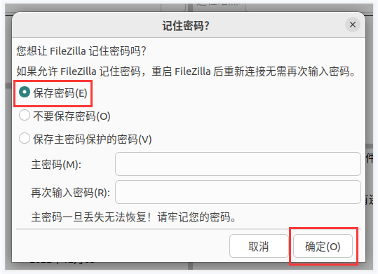
Then select Always trust this host and click OK


- After the connection is successful, you can see the directory structure of the development board's Linux file system on the right side of the filezilla software.

- Then select the path to be uploaded to the development board on the right side of the filezilla software, select the file to be uploaded in Ubuntu PC on the left side of the filezilla software, right-click the mouse, and then click the upload option to start uploading the file to the development board.

After the upload is completed, you can go to the corresponding path in the development board Linux system to view the uploaded file.
The method of uploading a folder is the same as the method of uploading a file, so I won't go into details here.
Method to upload files from Windows PC to development board Linux system
How to upload files using filezilla
- First download the installation file of the Windows version of the filezilla software. The download link is as follows


The downloaded installation package is as shown below, then double-click to install it directly
FileZilla_Server_1.5.1_win64-setup.exe
During the installation process, please select Decline on the following installation interface, and then select Next>
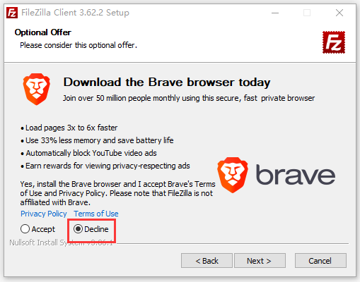

- The interface after opening filezilla is as shown below. At this time, the remote site on the right is empty.

- The method of connecting the development board is as shown in the figure below:
- Then choose to save the password and click OK

- Then select Always trust this host and click OK

- After the connection is successful, you can see the directory structure of the development board's Linux file system on the right side of the filezilla software.

- Then select the path to be uploaded to the development board on the right side of the filezilla software, select the file to be uploaded on the Windows PC on the left side of the filezilla software, right-click the mouse, and then click the upload option to start uploading the file to the development board.

After the upload is completed, you can go to the corresponding path in the development board Linux system to view the uploaded file.
The method of uploading a folder is the same as the method of uploading a file, so I won't go into details here.
Instructions for using the logo on and off the machine
The power on/off logo will only be displayed on the desktop version of the system by default.
Set the bootlogo variable to false in /boot/orangepiEnv.txt to turn off the switch logo.
orangepi@orangepi:~$ sudo vim /boot/orangepiEnv.txt
verbosity=1
bootlogo=false
Set the bootlogo variable to true in /boot/orangepiEnv.txt to enable the power on/off logo.
orangepi@orangepi:~$ sudo vim /boot/orangepiEnv.txt
verbosity=1
bootlogo=true
The location of the boot logo picture in the Linux system is
/usr/share/plymouth/themes/orangepi/watermark.png
After replacing the boot logo image, you need to run the following command to take effect
orangepi@orangepi:~$ sudo update-initramfs -u
How to turn on the power button in Linux5.4
There is no power on/off button on the main board of the development board. We can expand it through a 24pin expansion board. The location of the power on/off button on the expansion board is as follows:

The power on/off button of the Linux 6.1 image is turned on by default, but the power on/off button of the Linux 5.4 kernel image is turned off by default and needs to be turned on manually for normal use. The steps are as follows:
First run orangepi-config. Ordinary users remember to add sudo permissions.
orangepi@orangepi:~$ sudo orangepi-config
Then select System
Then select Hardware
Then use the keyboard's arrow keys to locate the position shown in the picture below, and then use the space to select the dtbo configuration of the SPI you want to open.

Then select <Save> to save
Then select <Back>
Then select <Reboot> to restart the system to make the configuration take effect.

How to shut down and restart the development board
During the running of the Linux system, if you directly unplug the power supply, it may cause the file system to lose some data. It is recommended to use the poweroff command to shut down the Linux system of the development board before powering off, and then unplug the power supply.
orangepi@orangepi:~$ sudo poweroff
Note that after turning off the development board, you need to unplug and replug the power supply before it can be turned on.
In addition to using the poweroff command to shut down, you can also use the power on/off button on the expansion board to shut down.
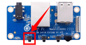
Note that Linux 5.4 requires manual configuration of the power on/off button before it can be used. For the opening method, please refer to the method of opening the power button in Linux5.4.
Use the reboot command to restart the Linux system in the development board
orangepi@orangepi:~$ sudo reboot
Linux SDK——orangepi-build usage instructions
Compilation system requirements
The Linux SDK, orangepi-build, only supports running on X64 computers with Ubuntu 22.04 installed. Therefore, before downloading orangepi-build, please first ensure that the Ubuntu version installed on your computer is Ubuntu 22.04. The command to check the Ubuntu version installed on the computer is as follows. If the Release field does not display 22.04, it means that the Ubuntu version currently used does not meet the requirements. Please change the system before performing the following operations.
|
test@test:~$ lsb_release -a No LSB modules are available. Distributor ID: Ubuntu Description: Ubuntu 22.04 LTS Release: 22.04 Codename: jammy |
If the computer is installed with a Windows system and does not have Ubuntu 22.04 installed on it, you can consider usingVirtualBox or VMware to install an Ubuntu 22.04 virtual machine in the Windows system. But please note, do not compile orangepi-build on the WSL virtual machine, because orangepi-build has not been tested in the WSL virtual machine, so there is no guarantee that orangepi-build can be used normally in WSL. In addition, please do not compile the Linux system on the development board. Use orangepi-build. The installation image download address of Ubuntu 22.04 amd64 version is:
|
https://mirrors.tuna.tsinghua.edu.cn/ubuntu-releases/22.04/ubuntu-22.04-desktop-amd64.iso |
After installing Ubuntu 22.04 on your computer or virtual machine, please first set the software source of Ubuntu 22.04 to Tsinghua source (or other domestic sources that you think is fast), otherwise it is easy to make errors due to network reasons when installing the software later. The steps to replace Tsinghua Source are as follows:
- For the method of replacing Tsinghua Source, please refer to the instructions on this page.
- Note that the Ubuntu version needs to be switched to 22.04.

- The contents of the /etc/apt/sources.list file that need to be replaced are:
|
test@test:~$ sudo mv /etc/apt/sources.list cat /etc/apt/sources.list.bak test@test:~$ sudo vim /etc/apt/sources.list # The source code image is commented by default to improve apt update speed. You can uncomment it yourself if necessary. deb https://mirrors.tuna.tsinghua.edu.cn/ubuntu/ jammy main restricted universe multiverse # deb-src https://mirrors.tuna.tsinghua.edu.cn/ubuntu/ jammy main restricted universe multiverse deb https://mirrors.tuna.tsinghua.edu.cn/ubuntu/ jammy-updates main restricted universe multiverse # deb-src https://mirrors.tuna.tsinghua.edu.cn/ubuntu/ jammy-updates main restricted universe multiverse deb https://mirrors.tuna.tsinghua.edu.cn/ubuntu/ jammy-backports main restricted universe multiverse # deb-src https://mirrors.tuna.tsinghua.edu.cn/ubuntu/ jammy-backports main restricted universe multiverse deb https://mirrors.tuna.tsinghua.edu.cn/ubuntu/ jammy-security main restricted universe multiverse # deb-src https://mirrors.tuna.tsinghua.edu.cn/ubuntu/ jammy-security main restricted universe multiverse
# deb https://mirrors.tuna.tsinghua.edu.cn/ubuntu/ jammy-proposed main restricted universe multiverse # deb-src https://mirrors.tuna.tsinghua.edu.cn/ubuntu/ jammy-proposed main restricted universe multiverse |
- After the replacement, you need to update the package information and ensure that no errors are reported.
|
test@test:~$ sudo apt-get update |
- In addition, since the source code of the kernel and Uboot are stored on GitHub, it is very important to ensure that the computer can download the code from GitHub normally when compiling the image.
Obtain the source code of linux sdk
Download orangepi-build from github
Linux sdk refers to the orangepi-build set of codes. Orangepi-build is modified based on the armbian build compilation system. Multiple versions of Linux images can be compiled using orangepi-build. Use the following command to download the orangepi-build code:
|
test@test:~$ sudo apt-get update test@test:~$ sudo apt-get install -y git test@test:~$ git clone https://github.com/orangepi-xunlong/orangepi-build.git -b next |
|
Note that when using the H618 Soc development board, you need to download the source code of the next branch of orangepi-build. The above git clone command needs to specify the branch of the orangepi-build source code as next.  |
|
When downloading the orangepi-build code through the git clone command, you do not need to enter the user name and password of the github account (the same is true for downloading other codes in this manual). If after entering the git clone command, Ubuntu PC prompts you to enter the user name of the github account. The name and password are usually entered incorrectly in the address of the orangepi-build warehouse behind git clone. Please carefully check whether there are any errors in the spelling of the command, rather than thinking that we have forgotten to provide the username and password of the github account. |
The u-boot and linux kernel versions currently used by the H618 series development boards are as follows:
| branch | u-boot Version | linux Kernel version |
| current | u-boot v2018.05 | linux5.4 |
| next | u-boot v2021.07 | linux6.1 |
|
The branch mentioned here is not the same thing as the branch of orangepi-build source code, please don't get confused. This branch is mainly used to distinguish different kernel source code versions. We define the linux5.4 bsp kernel currently provided by Allwinner as the current branch. The latest linux6.1 LTS kernel is defined as the next branch. |
After downloading, the following files and folders will be included:
build.sh: Compile startup script
external: Contains configuration files needed to compile the image, specific scripts, and source code of some programs, etc.
LICENSE: GPL 2 license file
README.md: orangepi-build documentation
scripts: Common script for compiling linux images
|
test@test:~/orangepi-build$ ls build.sh external LICENSE README.md scripts |
|
If you downloaded the orangepi-build code from github, after downloading, you may find that orangepi-build does not contain the source code of u-boot and linux kernel, and there is no cross-compilation tool required to compile u-boot and linux kernel. chain, this is normal, because these things are stored in other separate github repositories or some servers (their addresses will be detailed below). Orangepi-build will specify the addresses of u-boot, Linux kernel and cross-compilation tool chain in the script and configuration file. When running orangepi-build, when it finds that these things are not available locally, it will automatically download them from the corresponding places. |
Download the cross-compilation tool chain
When orangepi-build is run for the first time, it will automatically download the cross-compilation toolchain and put it in the toolchains folder. Every time you run orangepi-build's build.sh script, it will check whether the cross-compilation toolchain in toolchains exists. If If it does not exist, the download will be restarted. If it exists, it will be used directly without repeated downloading.

The mirror URL of the cross-compilation tool chain in China is the open source software mirror site of Tsinghua University:
|
https://mirrors.tuna.tsinghua.edu.cn/armbian-releases/_toolchain/ |
After toolchains is downloaded, it will contain multiple versions of cross-compilation toolchain:
|
test@test:~/orangepi-build$ ls toolchains/ gcc-arm-11.2-2022.02-x86_64-aarch64-none-linux-gnu gcc-linaro-4.9.4-2017.01-x86_64_aarch64-linux-gnu gcc-linaro-7.4.1-2019.02-x86_64_arm-linux-gnueabi gcc-arm-11.2-2022.02-x86_64-arm-none-linux-gnueabihf gcc-linaro-4.9.4-2017.01-x86_64_arm-linux-gnueabi gcc-linaro-aarch64-none-elf-4.8-2013.11_linux gcc-arm-9.2-2019.12-x86_64-aarch64-none-linux-gnu gcc-linaro-5.5.0-2017.10-x86_64_arm-linux-gnueabihf gcc-linaro-arm-linux-gnueabihf-4.8-2014.04_linux gcc-arm-9.2-2019.12-x86_64-arm-none-linux-gnueabihf gcc-linaro-7.4.1-2019.02-x86_64_aarch64-linux-gnu gcc-linaro-arm-none-eabi-4.8-2014.04_linux |
The cross-compilation tool chain used to compile the H618 Linux kernel source code is:
- linux5.4
|
gcc-arm-11.2-2022.02-x86_64-aarch64-none-linux-gnu |
- linux6.1
|
gcc-arm-11.2-2022.02-x86_64-aarch64-none-linux-gnu |
The cross-compilation tool chain used to compile the H618 u-boot source code is:
- v2018.05
|
gcc-linaro-7.4.1-2019.02-x86_64_arm-linux-gnueabi |
- v2021.07
|
gcc-arm-11.2-2022.02-x86_64-aarch64-none-linux-gnu |
orangepi-build complete directory structure description
After downloading, the orangepi-build warehouse does not contain the source code of the linux kernel, u-boot and cross-compilation tool chain. The source code of the linux kernel and u-boot is stored in an independent git warehouse.
The git warehouse where the linux kernel source code is stored is as follows. Please note that the branch of the linux-orangepi warehouse is switched to
- a) Linux5.4
https://github.com/orangepi-xunlong/linux-orangepi/tree/orange-pi-5.4-sun50iw9
- b) Linux6.1
https://github.com/orangepi-xunlong/linux-orangepi/tree/orange-pi-6.1-sun50iw9
The git warehouse where the u-boot source code is stored is as follows. Please note that the branch of the u-boot-orangepi warehouse is switched to
- a) v2018.05
https://github.com/orangepi-xunlong/u-boot-orangepi/tree/v2018.05-h618
- b) v2021.07
https://github.com/orangepi-xunlong/u-boot-orangepi/tree/v2021.07-sunxi
When orangepi-build is run for the first time, it will download the cross-compilation tool chain, u-boot and linux kernel source code. After successfully compiling a linux image, the files and folders that can be seen in orangepi-build are:
build.sh: Compile startup script
external: Contains the configuration files needed to compile the image, scripts for specific functions, and the source code of some programs. The rootfs compressed package cached during the image compilation process is also stored in external.
kernel: Store the source code of the linux kernel
LICENSE: GPL 2 license file
README.md: orangepi-build documentation
output: Store compiled u-boot, linux and other deb packages, compilation logs, and compiled images and other files
scripts: Common script for compiling linux images
toolchains: Store cross-compilation tool chain
u-boot: Store the source code of u-boot
userpatches: Store the configuration files needed to compile the script
test@test:~/orangepi-build$ ls
build.sh external kernel LICENSE output README.md scripts toolchains u-boot userpatches
Compile u-boot
- Run the build.sh script, remember to add sudo permissions
|
test@test:~/orangepi-build$ sudo ./build.sh |
- Select U-boot package and press Enter

- Then select the model of the development board

Then select the branch type of u-boot
The current branch will compile the u-boot v2018.05 version code that needs to be used by the linux5.4 image.
The next branch will compile the u-boot v2021.07 version code that needs to be used by the linux6.1 image.

If you select the next branch, you will also be prompted to select the memory size, and you do not need to select the current branch.
If the development board you purchased has a memory size of 1.5GB, please select the first option.
If the development board you purchased has 1GB or 2GB or 4GB memory size, please choose the second option.


Then it will start to compile u-boot. Some of the information prompted when compiling the next branch is as follows:
- Version of u-boot source code
[ o.k. ] Compiling u-boot [ v2021.07 ]
- Version of the cross-compilation tool chain
[ o.k. ] Compiler version [ aarch64-linux-gnu-gcc 11 ]
- Path to the compiled u-boot deb package
[ o.k. ] Target directory [ orangepi-build/output/debs/u-boot ]
- The package name of the compiled u-boot deb package
[ o.k. ] File name [ linux-u-boot-next-orangepizero2w_x.x.x_arm64.deb ]
- Compilation time
[ o.k. ] Runtime [ 1 min ]
- Repeat the command to compile u-boot. Use the following command without selecting through the graphical interface. You can start compiling u-boot directly.
[ o.k. ] Repeat Build Options [ sudo ./build.sh BOARD=orangepizero2w BRANCH=next BUILD_OPT=u-boot ]
- View the compiled u-boot deb package
|
test@test:~/orangepi-build$ ls output/debs/u-boot/ linux-u-boot-next-orangepizero2w_x.x.x_arm64.deb |
- When the orangepi-bulid compilation system compiles the u-boot source code, it will first synchronize the u-boot source code with the u-boot source code of the github server. Therefore, if you want to modify the u-boot source code, you first need to turn off the download and update function of the source code. (You need to completely compile u-boot before you can turn off this function, otherwise it will prompt that the source code of u-boot cannot be found), otherwise the modifications will be restored. The method is as follows:
Set the IGNORE_UPDATES variable in uuserpatches/config-default.conf to "yes"
|
test@test:~/orangepi-build$ vim userpatches/config-default.conf ...... IGNORE_UPDATES="yes" ...... |
When debugging u-boot code, you can use the following method to update u-boot in the linux image for testing
- First upload the compiled deb package of u-boot to the Linux system of the development board.
test@test:~/orangepi-build$ cd output/debs/u-boot
test@test:~/orangepi_build/output/debs/u-boot$ scp \
linux-u-boot-next-orangepizero2w_x.x.x_arm64.deb root@192.168.1.xxx:/root
- Install the new u-boot deb package just uploaded
orangepi@orangepi:~$ sudo dpkg -i linux-u-boot-next-orangepizero2w_x.x.x_arm64.deb
- Then run the nand-sata-install script
orangepi@orangepi:~$ sudo nand-sata-install
- Then select 5 Install/Update the bootloader on SD/eMMC
- After pressing the Enter key, a Warning will pop up first.
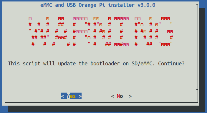
- Press the Enter key again to start updating u-boot. After the update is completed, the following information will be displayed.
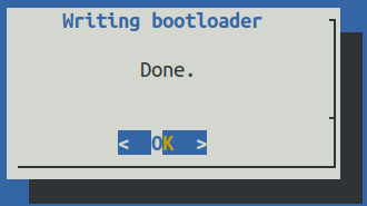
- Then you can restart the development board to test whether the u-boot modification has taken effect.


Compile the linux kernel
- Run the build.sh script, remember to add sudo permissions
test@test:~/orangepi-build$ sudo ./build.sh
- Select Kernel package and press Enter

- Then you will be prompted whether you need to display the kernel configuration interface. If you do not need to modify the kernel configuration, select the first one. If you need to modify the kernel configuration, select the second one.

- Then select the model of the development board
- Then select the branch type of the kernel source code
- a. The current branch will compile the linux5.4 kernel source code
- b. The next branch will compile the linux6.1 kernel source code
- If you choose to display the kernel configuration menu (the second option) in step 3), the kernel configuration interface opened through make menuconfig will pop up. At this time, you can directly modify the kernel configuration. After modification, save and exit. Yes, compilation of the kernel source code will begin after exiting.
- If you do not need to modify the kernel configuration options, when running the build.sh script, pass KERNEL_CONFIGURE=no to temporarily block the pop-up of the kernel configuration interface.
b. You can also set KERNEL_CONFIGURE=no in the orangepi-build/userpatches/config-default.confconfiguration file to permanently disable this function.
If the following error is prompted when compiling the kernel, it is because the Ubuntu PC terminal interface is too small, causing the make menuconfig interface to be unable to be displayed. Please increase the Ubuntu PC terminal to the maximum size, and then rerun the build.sh script.

|
test@test:~/orangepi-build$ sudo ./build.sh KERNEL_CONFIGURE=no |

Part of the information prompted when compiling the next branch kernel source code is explained as follows:
- Version of the linux kernel source code
[ o.k. ] Compiling current kernel [ 6.1.31 ]
- The version of the cross-compilation tool chain used
[ o.k. ] Compiler version [ aarch64-linux-gnu-gcc 11 ]
- The default configuration file used by the kernel and the path where it is stored are as follows
[ o.k. ] Using kernel config file [ orangepi-build/external/config/kernel/linux-6.1-sun50iw9-next.config ]
- The path to the kernel-related deb package generated by compilation
[ o.k. ] Target directory [ output/debs/ ]
- The package name of the kernel image deb package generated by compilation
[ o.k. ] File name [ linux-image-next-sun50iw9_x.x.x_arm64.deb ]
- Compilation time
[ o.k. ] Runtime [ 10 min ]
- Finally, the compilation command to repeatedly compile the last selected kernel will be displayed. Use the following command without selecting through the graphical interface, and you can directly start compiling the kernel source code.
[ o.k. ] Repeat Build Options [ sudo ./build.sh BOARD=orangepizero2w BRANCH=next BUILD_OPT=kernel KERNEL_CONFIGURE=no ]
View the kernel-related deb package generated by compilation
linux-dtb-next-sun50iw9_x.x.x_arm64.deb Contains dtb files used by the kernel
linux-headers-next-sun50iw9_x.x.x_arm64.deb Contains kernel header files
linux-image-next-sun50iw9_x.x.x_arm64.deb Contains kernel images and kernel modules
test@test:~/orangepi-build$ ls output/debs/linux-*
output/debs/linux-dtb-next-sun50iw9_x.x.x_arm64.deb
output/debs/linux-headers-next-sun50iw9_x.x.x_arm64.deb
output/debs/linux-image-next-sun50iw9_x.x.x_arm64.deb
- When the orangepi-bulid compilation system compiles the linux kernel source code, it will first synchronize the linux kernel source code with the linux kernel source code of the github server. Therefore, if you want to modify the linux kernel source code, you first need to turn off the update function of the source code (it needs to be completely compiled once This function can only be turned off after obtaining the Linux kernel source code, otherwise it will prompt that the source code of the Linux kernel cannot be found), otherwise the modifications will be restored. The method is as follows:
Set the IGNORE_UPDATES variable in userpatches/config-default.conf to "yes"
|
test@test:~/orangepi-build$ vim userpatches/config-default.conf IGNORE_UPDATES="yes" |
If the kernel is modified, you can use the following method to update the kernel and kernel module of the development board Linux system
- Upload the compiled deb package of the Linux kernel to the Linux system of the development board
test@test:~/orangepi-build$ cd output/debs
test@test:~/orangepi-build/output/debs$ scp \
linux-image-next-sun50iw9_x.x.x_arm64.deb root@192.168.1.xxx:/root
- Install the deb package of the new linux kernel just uploaded.
orangepi@orangepi:~$ sudo dpkg -i linux-image-next-sun50iw9_x.x.x_arm64.deb
- Then restart the development board and check whether the kernel-related modifications have taken effect.
orangepi@orangepi:~$ sudo reboot
Compile rootfs
- Run the build.sh script, remember to add sudo permissions
test@test:~/orangepi-build$ sudo ./build.sh
- Select Rootfs and all deb packages and press Enter

- Then select the model of the development board
Then select the branch type of the kernel source code. Different versions of the kernel source code maintain different rootfs types.
In the current branch, you can see three options: debian11, ubuntu20.04, and ubuntu22.04.
In the next branch, you can see three options: debian11, debian12, and ubuntu22.04.
- Then select the type of rootfs

Then select the type of image
Image with console interface (server) Represents the image of the server version, which is relatively small in size.
Image with desktop environment Represents an image with a desktop, which is relatively large in size.


- If you are compiling the server version of the image, you can also choose to compile the Standard version or the Minimal version. The Minimal version will have much less pre-installed software than the Standard version (please do not choose the Minimal version without special needs, because many things are not pre-installed by default. Some functions may not be available)

- If you are compiling a desktop version of the image, you also need to select the type of desktop environment. Currently, only XFCE is maintained, so please select an XFCE type desktop.


You can then select additional packages that need to be installed. Please press the Enter key here to skip directly.

Then the compilation of rootfs will start. Some of the information prompted during compilation are as follows:
- Type of rootfs
[ o.k. ] local not found [ Creating new rootfs cache for bullseye ]
- The storage path of the compiled rootfs compressed package
[ o.k. ] Target directory [ orangepi-build/external/cache/rootfs ]
- The name of the rootfs compressed package generated by compilation
[ o.k. ] File name [ bullseye-xfce-arm64.5250ec7002de9e81a41de169f1f89721.tar.lz4 ]
View the compiled rootfs compressed package
- bullseye-xfce-arm64.5250ec7002de9e81a41de169f1f89721.tar.lz4 It is a compressed package of rootfs. The meaning of each field in the name is
- a) bullseye represents the type of Linux distribution of rootfs
- b) xfce indicates that the rootfs is the desktop version, and if it is cli, it indicates the server version.
- c) arm64 represents the architecture type of rootfs
- d) 25250ec7002de9e81a41de169f1f89721 is the MD5 hash value generated by the package names of all software packages installed by rootfs. As long as the list of software packages installed by rootfs is not modified, this value will not change. The compilation script will use this MD5 hash value. Determine whether rootfs needs to be recompiled
- bullseye-xfce-arm64.5250ec7002de9e81a41de169f1f89721.tar.lz4.list Lists the package names of all packages installed by rootfs
test@test:~/orangepi-build$ ls external/cache/rootfs/
bullseye-xfce-arm64.5250ec7002de9e81a41de169f1f89721.tar.lz4
bullseye-xfce-arm64.5250ec7002de9e81a41de169f1f89721.tar.lz4.current
bullseye-xfce-arm64.5250ec7002de9e81a41de169f1f89721.tar.lz4.list
- If the required rootfs already exists under external/cache/rootfs, then compiling the rootfs again will directly skip the compilation process and will not restart the compilation. When compiling the image, it will also go to external/cache/rootfs to check whether it already exists. There is a cached rootfs available. If it is available, use it directly. This can save a lot of download and compilation time.
Compile linux image
- Run the build.sh script, remember to add sudo permissions
test@test:~/orangepi-build$ sudo ./build.sh
- Select Full OS image for flashing and press Enter

- Then select the model of the development board
Then select the branch type of the kernel source code. Different versions of the kernel source code maintain different rootfs types.
In the current branch, you can see three options: debian11, ubuntu20.04, and ubuntu22.04.
In the next branch, you can see three options: debian11, debian12, and ubuntu22.04.
If you select the next branch, you will also be prompted to select the memory size, and you do not need to select the current branch.
If the development board you purchased has a memory size of 1.5GB, please select the first option.
If the development board you purchased has 1GB or 2GB or 4GB memory size, please choose the second option.
Then select the type of rootfs
Then select the type of image
Image with console interface (server) Represents the image of the server version, which is relatively small in size.
Image with desktop environmentRepresents an image with a desktop, which is relatively large in size.
- If you are compiling the server version of the image, you can also choose to compile the Standard version or the Minimal version. The Minimal version will have much less pre-installed software than the Standard version (please do not choose the Minimal version without special needs, because many things are not pre-installed by default. Some functions may not be available)
- If you are compiling a desktop version of the image, you also need to select the type of desktop environment. Currently, only XFCE is maintained, so please select an XFCE type desktop.
You can then select additional packages that need to be installed. Please press the Enter key here to skip directly.
- Then the compilation of the linux image will begin. The general process of compilation is as follows
- a. Initialize the compilation environment of Ubuntu PC and install the software packages required for the compilation process.
- b. Download the source code of u-boot and linux kernel (if already cached, only update the code)
- c. Compile u-boot source code and generate u-boot deb package
- d. Compile linux source code and generate linux-related deb packages
- e. Make the deb package of linux firmware
- f. Make the deb package of orangepi-config tool
- g. Create a deb package with board-level support
- h. If you compile the desktop version image, you will also create a desktop-related deb package.
- i. Check whether rootfs has been cached. If not, re-create rootfs. If it has been cached, decompress it directly and use it.
- j. Install the deb package generated previously into rootfs
- k. Make some specific settings for different development boards and different types of images, such as pre-installing additional software packages, modifying system configurations, etc.
- l. Then create the image file and format the partition. The default type is ext4.
- m. Then copy the configured rootfs to the mirror partition.
- n. Then update initramfs
- o. Finally, write the bin file of u-boot into the image through the dd command.
After compiling the image, the following message will be displayed
- The storage path of the compiled image
[ o.k. ] Done building [ output/images/orangepizero2w_x.x.x_debian_bullseye_linux6.1.xx_xfce_desktop/orangepizero2w_x.x.x_debian_bullseye_linux6.1.xx_xfce_desktop.img ]
- Compilation time
[ o.k. ] Runtime [ 19 min ]
- Repeat the command to compile the image. Use the following command to start compiling the image directly without selecting it through the graphical interface.
[ o.k. ] Repeat Build Options [ sudo ./build.sh BOARD=orangepizero2w BRANCH=next BUILD_OPT=image RELEASE=bullseye BUILD_MINIMAL=no BUILD_DESKTOP=no KERNEL_CONFIGURE=yes ]
Instructions for using the Orange Pi OS Arch system
Orange Pi OS Arch system function adaptation status
| Motherboard functions | OPi OS Arch |
| HDMI video | OK |
| HDMI Audio | OK |
| Type-C USB2.0 x 2 | OK |
| TF Card Startup | OK |
| WIFI | OK |
| Bluetooth | OK |
| LED Light | OK |
| 40pin GPIO | OK |
| 40pin I2C | OK |
| 40pin SPI | OK |
| 40pin UART | OK |
| 40pin PWM | OK |
| Temperature Sensor | OK |
| Hardware watchdog | OK |
| Mali GPU | NO |
| Video codec | NO |
| 24pin expansion board function | OPi OS Arch |
| 100M network port | OK |
| 100M Ethernet port light | OK |
| USB2.0 HOST x 2 | OK |
| Infrared reception | OK |
| Headphone audio playback | OK |
| On/off button | OK |
| LRADC Custom buttons x 2 | OK |
| TV-OUT | NO |
Orange Pi OS Arch System User Guide Instructions
First of all, please note that the OPi OS Arch system does not have a default orangepi user and password, so you cannot directly log in remotely through the serial port and ssh after the system is started after burning (not even the root user). This is different from Ubuntu and Debian systems.
When the OPi OS Arch system is started for the first time, you need to connect an HDMI display and then initialize the system settings through the user wizard (including creating a new user name and setting a password). The setup steps of the user wizard are as follows:
After burning the system, when you start it for the first time and enter the desktop, you will see the user wizard program shown in the figure below.
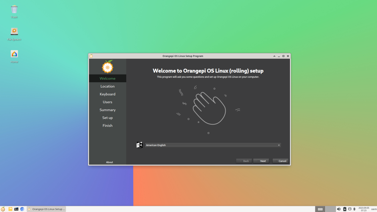
First you need to select the language you want
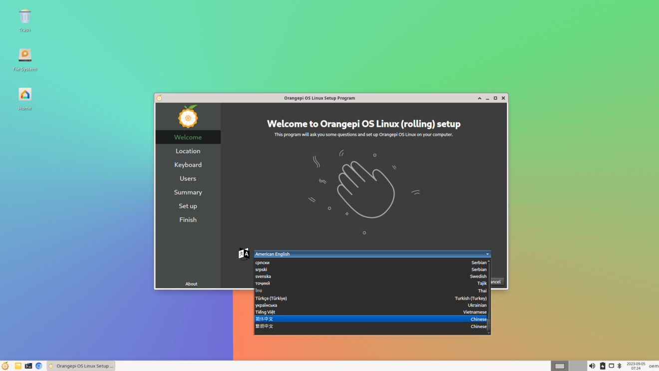
After selecting the language, the user wizard will immediately switch to the corresponding language interface, as shown below in Chinese
Then select the area
Then select the keyboard model
Then create a new username and set a password
Then make sure there is no problem with the selection, and then click the install button
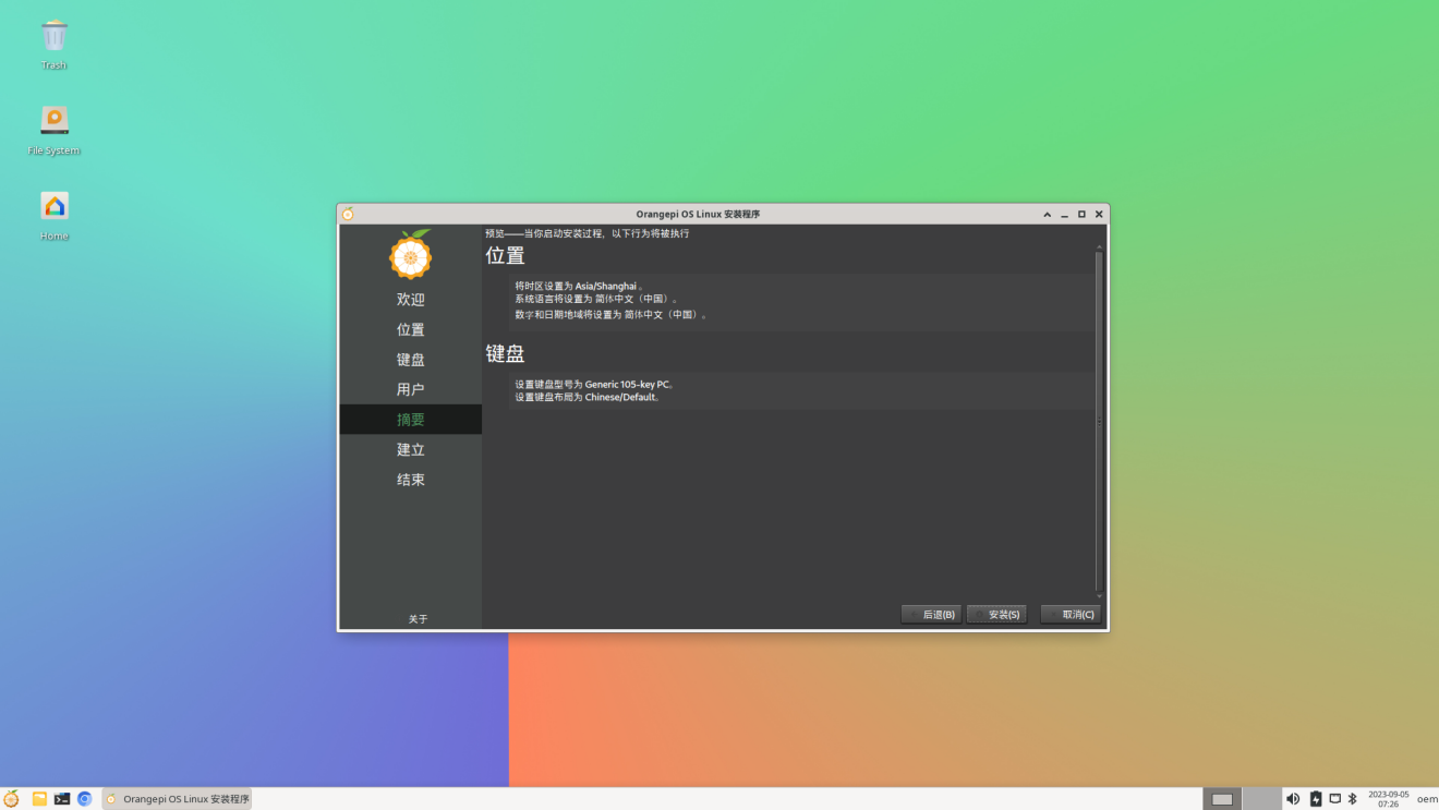
Then wait for the installation to complete
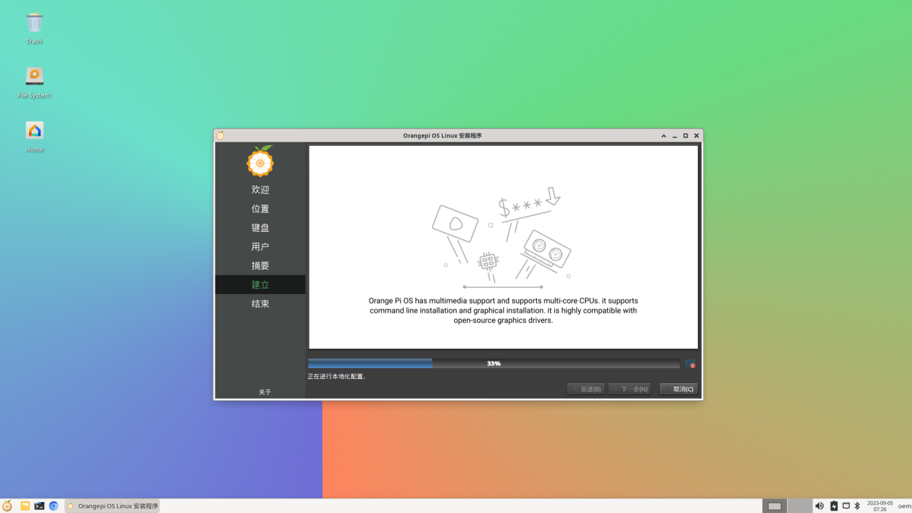
After the installation is complete, you need to click the Finish button to restart the system.
The Orange Pi Hello program will automatically start after restarting. At this time, you need to remove the check mark of Start on startup in the lower right corner, otherwise you need to manually close the Orange Pi Hello program every time you start it.
At this point, you can use the newly created username and password to log in to the OPi OS system through the serial port or ssh.


How to set DT overlays
The multiplexing functions such as I2C/SPI/UART/PWM in the 40-pin development board are turned off by default in the kernel's dts, and the corresponding DT overlays need to be manually turned on before they can be used.
The method to open DT overlays in OPi OS Arch system is as follows:
- First open the /boot/extlinux/extlinux.conf configuration file
[orangepi@orangepi-pc ~]$ sudo vim /boot/extlinux/extlinux.conf
- Then open the corresponding configuration by adding FDTOVERLAYS /dtbs/allwinner/overlay/xxx.dtbo in /boot/extlinux/extlinux.conf
|
Note that xxx.dtbo in FDTOVERLAYS /dtbs/allwinner/overlay/xxx.dtbo needs to be replaced with the specific dtbo configuration, please do not copy it. |
|
[orangepi@orangepi-pc ~]$ sudo vim /boot/extlinux/extlinux.conf LABEL Orange Pi KERNEL /Image FDT /dtbs/allwinner/sun50i-h616-orangepi-zero2w.dtb FDTOVERLAYS /dtbs/allwinner/overlay/xxx.dtbo #Configuration that needs to be added |
The storage path of xxx.dtbo in the OPi OS Arch image is as follows. Please note that not all dtbo under this path can be used.
/boot/dtbs/allwinner/overlay/
The DT overlays configuration that can be used by the development board is as follows
| Functions on the development board | Corresponding DT overlays configuration |
| 40pin - i2c0 | sun50i-h616-pi-i2c0.dtbo |
| 40pin - i2c1 | sun50i-h616-pi-i2c1.dtbo |
| 40pin - i2c2 | sun50i-h616-pi-i2c2.dtbo |
| 40pin - uart2 | sun50i-h616-pi-uart2.dtbo |
| 40pin - uart3 | sun50i-h616-pi-uart3.dtbo |
| 40pin - uart4 | sun50i-h616-pi-uart4.dtbo |
| 40pin - uart5 | sun50i-h616-ph-uart5.dtbo |
| 40pin - pwm1 | sun50i-h616-pi-pwm1.dtbo |
| 40pin - pwm2 | sun50i-h616-pi-pwm2.dtbo |
| 40pin - pwm3 | sun50i-h616-pi-pwm3.dtbo |
| 40pin - pwm4 | sun50i-h616-pi-pwm4.dtbo |
| 40pin - spi1 cs0 | sun50i-h616-spi1-cs0-spidev.dtbo |
| 40pin - spi1 cs1 | sun50i-h616-spi1-cs1-spidev.dtbo |
| 40pin - spi1 cs0 cs1 | sun50i-h616-spi1-cs0-cs1-spidev.dtbo |
| 设Set USB0 to Host mode | sun50i-h616-usb0-host.dtbo |
| Turn off the green LED light | sun50i-h616-zero2w-disable-led.dtbo |
| How to close the UART0 debugging serial port | sun50i-h616-disable-uart0.dtbo |
- If you need to open multiple configurations at the same time, just add the paths of multiple configurations directly after FDTOVERLAYS. For example, the configuration of opening i2c1 and uart5 at the same time is as follows
|
[orangepi@orangepi-pc ~]$ sudo vim /boot/extlinux/extlinux.conf LABEL Orange Pi KERNEL /Image FDT /dtbs/allwinner/sun50i-h616-orangepi-zero2w.dtb FDTOVERLAYS /dtbs/allwinner/overlay/sun50i-h616-pi-i2c1.dtbo /dtbs/allwinner/overlay/sun50i-h616-ph-uart5.dtbo |
- After setting, you need to restart the system for the configuration to take effect.
|
[orangepi@orangepi-pc ~]$ sudo reboot |
How to install software
You can use the pacman package management tool to install software that is not available in OPi OS. For example, the command to install the vim editor is as follows. If you want to install other software, you only need to replace vim with the package name of the software you want to install.
|
[orangepi@orangepi-pc ~]$ sudo pacman -Syy vim |
Android 12 TV system usage instructions
Supported Android versions
| Android Version | Kernel version |
| Android 12 TV Version | linux5.4 |
Android 12 TV function adaptation status
| Motherboard functions | Android12 TV |
| HDMI video | OK |
| HDMI Audio | OK |
| Type-C USB2.0 x 2 | OK |
| TF card startup | OK |
| WIFI | OK |
| Bluetooth | OK |
| USB Camera | OK |
| LED Light | OK |
| 40pin GPIO | OK |
| 40pin I2C | OK |
| 40pin SPI1 | OK |
| 40pin UART | OK |
| 40pin PWM | OK |
| Temperature Sensor | OK |
| Hardware watchdog | OK |
| Mali GPU | OK |
| Video codec | OK |
| 24pin Expansion board function | Android12 TV |
| 100M network port | OK |
| 100M Ethernet port light | OK |
| USB2.0 HOST x 2 | OK |
| Infrared reception | OK |
| Headphone audio playback | OK |
| On/off button | OK |
| LRADC Custom buttons x 2 | OK, The default setting is the volume up and down keys. |
| TV-OUT | OK |
Onboard LED light display instructions
| green light | red light | |
| u-boot startup phase | Off | on |
| Kernel boot to enter the system | on | on |
How to return to the previous interface in Android
We generally use the mouse and keyboard to control the Android system of the development board. When entering certain interfaces and need to return to the previous interface or desktop, we can only return by right-clicking the mouse, and the keyboard cannot return.
If you have purchased the infrared remote control (other remote controls do not work) and a 24pin expansion board that come with the development board, after connecting the 24pin expansion board to the development board, you can also use the return key on the remote control to return to the previous menu. The location of the return key is as shown below. Shown:

How to use ADB
Use network connection adb debugging
|
Using network adb does not require a USB Typc C interface data cable to connect the computer and the development board. Instead, it communicates through the network, so first make sure that the development board's wired or wireless network is connected, and then obtain the IP address of the development board. Next To be used. |
- Make sure the service.adb.tcp.port of the Android system is set to 5555 port number
apollo-p2:/ # getprop | grep "adb.tcp"
[service.adb.tcp.port]: [5555]
- If service.adb.tcp.port is not set, you can use the following command in the serial port to set the port number of the network adb
|
apollo-p2:/ # setprop service.adb.tcp.port 5555 apollo-p2:/ # stop adbd apollo-p2:/ # start adbd |
- Install adb tool on Ubuntu PC
|
test@test:~$ sudo apt-get update test@test:~$ sudo apt-get install -y adb |
- Then connect network adb on Ubuntu PC
|
test@test:~$ adb connect 192.168.1.xxx:5555 (Need to be modified to the IP address of the development board) * daemon not running; starting now at tcp:5037 * daemon started successfully connected to 192.168.1.xxx:5555
List of devices attached 192.168.1.xxx:5555 device |
- Then you can log in to the android system through adb shell on Ubuntu PC
|
test@test:~$ adb shell apollo-p2:/ # |
Use data cable to connect adb debugging
- Prepare a USB Type C interface data cable, plug one end of the USB interface into the USB interface of the computer, and plug one end of the USB Type C interface into the USB0 interface of the development board (see the description of the picture on the right below for the location of USB0). In this case, the development board is powered by the computer's USB interface, so please ensure that the computer's USB interface can provide the most sufficient power to drive the development board.


- Install adb tool on Ubuntu PC
|
test@test:~$ sudo apt-get update test@test:~$ sudo apt-get install -y adb |
- Check whether the ADB device is recognized
|
test@test:~$ adb devices List of devices attached 4c00146473c28651dd0 device |
- Then you can log in to the android system through adb shell on Ubuntu PC
|
test@test:~$ adb shell apollo-p2:/ $ |
View how to set HDMI display resolution
Enter first Settings
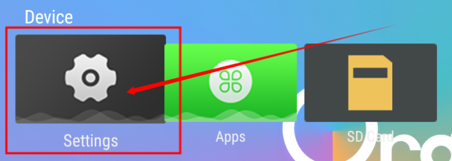
Then select Device Preferences
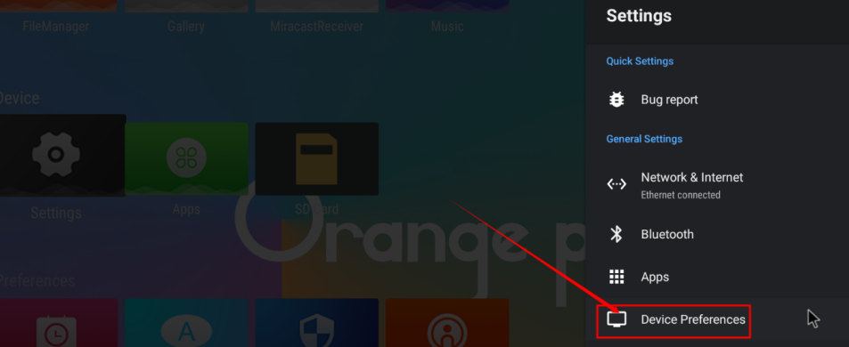
Then select Display & Sound
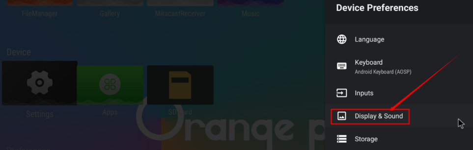
Then select Advanced display settings
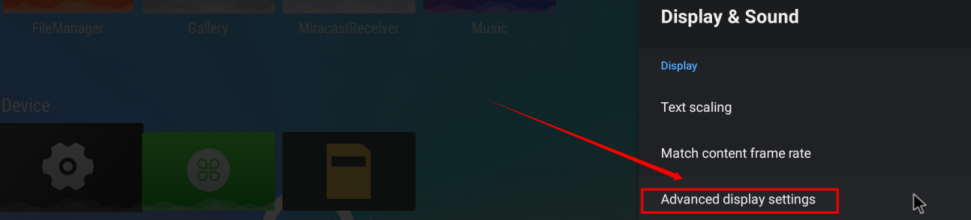
Then select HDMI output mode
Then you can see the list of resolutions supported by the monitor. At this time, clicking the corresponding option will switch to the corresponding resolution. Please note that different monitors may support different resolutions. If you connect it to a TV, you will generally see more resolution options than the picture below.
The HDMI output of the development board supports 4K display. When connected to a 4K TV, you can see the 4K resolution option.


HDMI to VGA display test
First you need to prepare the following accessories
- HDMI to VGA converter
- A VGA cable and a Mini HDMI male to HDMI female adapter
- A monitor or TV that supports VGA interface
- HDMI to VGA display test is as follows

|
When using HDMI to VGA display, the development board and the Android system of the development board do not need to make any settings. You only need the Mini HDMI interface of the development board to display normally. So if there is a problem with the test, please check whether there is a problem with the HDMI to VGA converter, VGA cable and monitor. |
WI-FI connection method
- Choose first Settings
- Then select Network & Internet

- Then turn on WI-FI

- After turning on WI-FI, you can see the searched signals under Available networks.

- After selecting the WI-FI you want to connect to, the password input interface shown below will pop up.

- Then use the keyboard to enter the password corresponding to the WI-FI, and then use the mouse to click the Enter button on the virtual keyboard to start connecting to the WI-FI.

- The display after successful WI-FI connection is as shown below

How to use WI-FI hotspot
- First, please make sure that the Ethernet port is connected to the network cable and can access the Internet normally.
- Then select Settings
- Then select Network & Internet
- Then select WIFI hotspot

- Then open Hotspot Enable. You can also see the name and password of the generated hotspot in the picture below. Remember them and use them when connecting to the hotspot (if you need to modify the name and password of the hotspot, you need to close Hotspot Enable first. Then you can modify it)

- At this time, you can take out your mobile phone. If everything is normal, you can find the WIFI hotspot with the same name (here AndroidAP_7132) shown under the Hotspot name in the picture above in the WI-FI list searched by the mobile phone. Then you can click AndroidAP_7132 to connect to the hotspot. The password can be seen under the Hotspot password in the picture above.

- After the connection is successful, it will be displayed as shown below (the interface will be different on different mobile phones, the specific interface is subject to the one displayed on your mobile phone). At this time, you can open a web page on your mobile phone to see if you can access the Internet. If the web page can be opened normally, it means that the WI-FI Hotspot of the development board can be used normally.

How to check the IP address of the Ethernet port
- There is no wired network interface on the main board of the development board. We can expand the 100M Ethernet through a 24pin expansion board.
Then make sure the network port of the expansion board is connected to the router or switch
Then open Settings
Then select Network & Internet
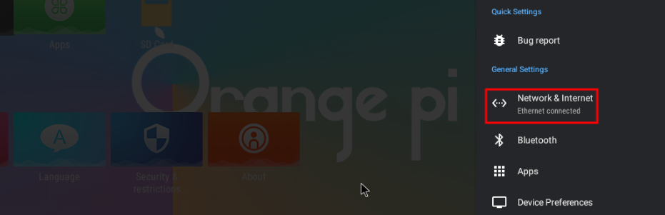
Then you can see the IP address of the development board's wired network port at the location shown in the picture below.
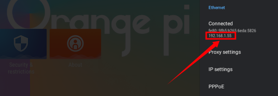


Bluetooth connection method
- Choose first Settings
- Then select Bluetooth

- Then Open Bluetooth Enable

- Then click Pair new deviceto start scanning for surrounding Bluetooth devices

- The searched Bluetooth devices will be displayed under Available devices

- Then click on the Bluetooth device you want to connect to start pairing. When the following interface pops up, please use the mouse to select the Pairoption

- What is tested here is the Bluetooth configuration process between the development board and the Android phone. At this time, the following confirmation interface will pop up on the phone. Click the pairing button on the phone to start the pairing process.

- After pairing is completed, open Paired devices and you will see the paired Bluetooth devices.

- At this time, you can use the Bluetooth of your mobile phone to send a picture to the development board. After sending, you can see the following confirmation interface in the Android system of the development board, and then click Accept to start receiving the pictures sent by the mobile phone.

- Pictures received by the Bluetooth system of the development board Android system can be viewed in Received files.

How to set USB0 to HOST mode
As shown in the figure below, there are two Type-C interfaces on the motherboard of the development board: USB0 and USB1. Both of these interfaces can be used to power the development board, and they can also be used as USB2.0 HOST interfaces. The difference between USB0 and USB1 is that in addition to being set to HOST mode, USB0 can also be set to Device mode, while USB1 only has HOST mode.
USB0 of the Android12 TV system released by Orange Pi is set to Device mode by default, so when there is no need to use USB0 Device mode (ADB function needs to ensure that USB0 is in Device mode), it is recommended to use USB0 for power supply, so that USB1 can be directly used to connect USB devices .
If you want to use USB0 to connect USB devices, you need to set USB0 to HOST mode. The method is as follows:
- Run the following command to set USB0 to HOST mode:
|
apollo-p2:/ # cat /sys/devices/platform/soc@3000000/soc@3000000\:usbc0@0/usb_host host_chose finished! apollo-p2:/ # |
- Run the following command to switch back to Device mode
|
apollo-p2:/ # cat /sys/devices/platform/soc@3000000/soc@3000000\:usbc0@0/usb_device device_chose finished! apollo-p2:/ # |
- The command to view the current mode of USB0 is
|
apollo-p2:/ # cat /sys/devices/platform/soc@3000000/soc@3000000\:usbc0@0/otg_role usb_host |
How to use USB camera
- First insert the USB (UVC protocol) camera into the USB interface of the development board
- If the USB camera is recognized normally, the corresponding video device node will be generated under /dev
console:/ # ls /dev/video0
/dev/video0
Then make sure that the adb connection between the Ubuntu PC and the development board is normal. For how to use adb, please refer to the instructions in the section "How to use ADB".
Download the USB camera test APP from the official tool on the development board information download page


- Then use the adb command to install the USB camera test APP into the Android system. Of course, you can also use a USB disk copy to install it.
|
test@test:~$ adb install usbcamera.apk |
- After installation, you can see the startup icon of the USB camera on the Android desktop.

- Then double-click to open the USB camera APP and you can see the output video of the USB camera.
Android system ROOT description
|
The Android system released by Orange Pi has been ROOT and can be tested using the following method. |
- Download from the official tool on the development board data download page rootcheck.apk

Then make sure that the adb connection between the Ubuntu PC and the development board is normal. For how to use adb, please refer to the instructions in the section "How to use ADB".
Then use the adb command to install rootcheck.apk into the Android system. Of course, you can also use a USB disk copy to install it.
|
test@test:~$ adb install rootcheck.apk |
- After installation, you can see the startup icon of the ROOT test tool on the Android desktop.

- The display interface after opening the ROOT test tool for the first time is as shown below

- Then you can click CHECK NOW to start checking the ROOT status of the Android system. After the check is completed, the display is as follows. You can see that the Android system has obtained ROOT permissions.

How to use MiracastReceiver to cast the mobile phone screen to the development board
First, please make sure that both the development board and the mobile phone are connected to the same WIFI hotspot. For the method of connecting the development board to WIFI, please refer to the instructions in the WI-FI connection method.
Then open the MiracastReceiverapplication in the Android system of the development board
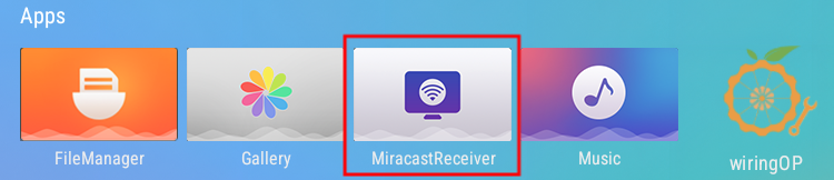
The interface after MiracastReceiver is opened is as follows
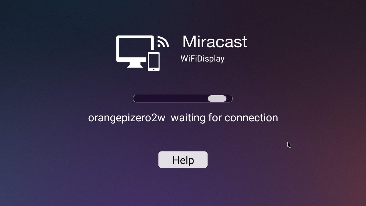
Then find the screen mirroring function in the phone settings. Here we take Xiaomi 12S Pro mobile phone as an example. Please research other brands of mobile phones by yourself. As shown in the picture below, click the button in the red box to open the screen mirroring function of the phone.

After waiting for a period of time, you will be able to see the searched connectable devices on your mobile phone, and then we can select the device corresponding to the development board to connect.
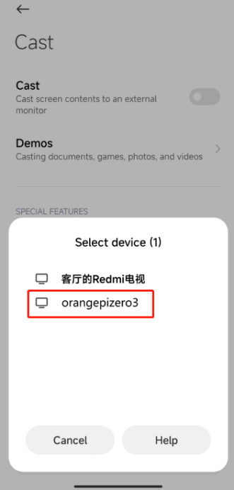
Then the selection box shown in the figure below will pop up in the MiracastReceiver application interface of the development board. Here we can select Accept
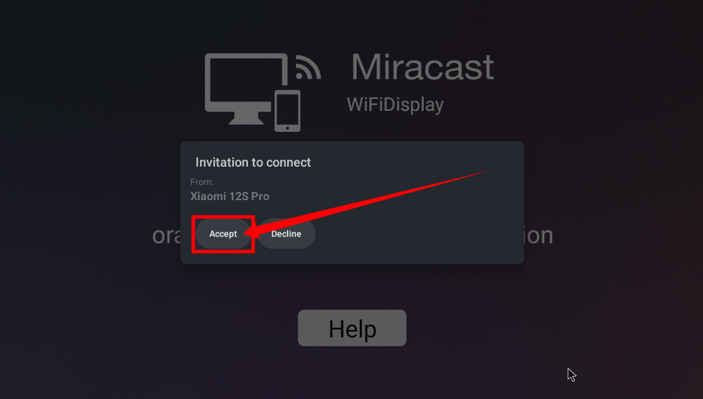
Then you can see the content of the mobile phone screen on the HDMI screen connected to the development board


Method of turning on and off the machine through buttons or infrared remote control
We can turn off or turn on the Android system of the development board through the power on/off button or infrared remote control. However, it should be noted that there is no power on/off button and infrared receiver on the main board of the development board, and it needs to be expanded through a 24pin expansion board.
The location of the power button on the 24pin expansion board is as shown in the figure below:
The location of the infrared remote control power button is as follows:

When shutting down, we need to press and hold the power button or the power button on the infrared remote control, and then the Android system will pop up the confirmation dialog box shown in the figure below, and then select OK to shut down the Android system.

After shutting down, press and hold the power button or the power button on the infrared remote control again to turn it on.
40pin interface GPIO, UART, SPI test
|
Note: The pin header on the 40pin interface is not soldered by default, and you need to solder it yourself before it can be used. |
40pin GPIO port test method
- First open wiringOP APP on the desktop
- Then click the GPIO_TEST button to open the GPIO test interface

- The GPIO test interface is as shown in the figure below. The two rows of CheckBox buttons on the left have a one-to-one correspondence with the 40pin pins. When the CheckBox button is checked, the corresponding GPIO pin will be set to OUT mode and the pin level is set to high level; when unchecked, the GPIO pin level will be set to low level; when the GPIO is clicked When you click the GPIO READALL button, you can get information such as wPi number, GPIO mode, pin level, etc.; when you click theBLINK ALL GPIO button, all GPIO ports will cycle through outputting high and low levels. This function can be used to test all the 40pin pins. GPIO port.

- Then click the GPIO READALL button, and the output information is as shown below:

- There are a total of 28 GPIO ports available in the 40-pin development board. The following takes pin 12 - corresponding to GPIO PI01 - corresponding to wPi serial number 6 - as an example to demonstrate how to set the high and low levels of the GPIO port. First click the CheckBox button corresponding to pin 12. When the button is selected, pin 12 will be set to high level. After setting, you can use a multimeter to measure the value of the voltage of the pin. If it is 3.3v, it means the setting High level success.

- Then click the GPIO READALL button and you can see that the current pin 12 mode is OUT and the pin level is high level.

- Click the CheckBox button in the picture below again to uncheck it, and pin 12 will be set to low level. After setting, you can use a multimeter to measure the voltage value of the pin. If it is 0v, it means the low level setting is successful.

- Then click the GPIO READALL button and you can see that the current pin 12 mode is OUT and the pin level is low level.

40pin UART test method
- As can be seen from the table below, the default uarts available in the Android12 TV system are uart2 and uart5. Please note that uart0 is set as a debugging serial port by default. Please do not use uart0 as a normal serial port.
GPIO NO. GPIO Function Pin 3.3V 1 264 PI8 TWI1-SDA 3 263 PI7 TWI1-SCL 5 269 PI13 PWM3 7 GND 9 226 PH2 UART5_TX 11 227 PH3 UART5_RX 13 261 PI5 UART2_TX 15 3.3V 17 231 PH7 SPI1_MOSI 19 232 PH8 SPI1_MISO 21 230 PH6 SPI1_CLK 23 GND 25 266 PI10 TWI2-SDA 27 256 PI0 29 271 PI15 31 268 PI12 PWM2 33 258 PI2 35 272 PI16 37 GND 39
| Pin | Function | GPIO | GPIO NO. |
| 2 | 5V | ||
| 4 | 5V | ||
| 6 | GND | ||
| 8 | UART0_TX | PH0 | 224 |
| 10 | UART0_RX | PH1 | 225 |
| 12 | PI1 | 257 | |
| 14 | GND | ||
| 16 | PWM4 | PI14 | 270 |
| 18 | PH4 | 228 | |
| 20 | GND | ||
| 22 | UART2_RX | PI6 | 262 |
| 24 | SPI1_CS0 | PH5 | 229 |
| 26 | SPI1_CS1 | PH9 | 233 |
| 28 | TWI2-SCL | PI9 | 265 |
| 30 | GND | ||
| 32 | PWM1 | PI11 | 267 |
| 34 | GND | ||
| 36 | PC12 | 76 | |
| 38 | PI4 | 260 | |
| 40 | PI3 | 259 |
- The device node corresponding to uart2 is /dev/ttyAS2, and the device node corresponding to uart5 is/dev/ttyAS5
|
apollo-p2:/ # ls /dev/ttyAS* /dev/ttyAS0 /dev/ttyAS1 /dev/ttyAS2 /dev/ttyAS5 |
- First open wiringOP APP on the desktop

- Then click the UART_TESTbutton to open the UART test interface

- The serial port test interface of wiringOP is as shown in the figure below

Then select the /dev/ttyAS2 or/dev/ttyAS5 node in the selection box
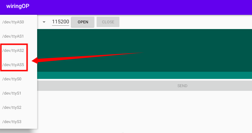
Enter the baud rate you want to set in the edit box, and then click the OPEN button to open the uart node. After the opening is successful, the OPEN button becomes unselectable, and the CLOSE button and SEND button become selectable.


Then use Dupont wire to short the rx and tx pins of uart
Then you can enter a paragraph of characters in the send edit box below and click the SEND button to start sending.

- If everything is normal, the received string will be displayed in the receiving box

40pin SPI test method
- As can be seen from the table below, the spi available for the 40pin interface is spi1, and there are two chip select pins cs0 and cs1
GPIO NO. GPIO Function Pin 3.3V 1 264 PI8 TWI1-SDA 3 263 PI7 TWI1-SCL 5 269 PI13 PWM3 7 GND 9 226 PH2 UART5_TX 11 227 PH3 UART5_RX 13 261 PI5 UART2_TX 15 3.3V 17 231 PH7 SPI1_MOSI 19 232 PH8 SPI1_MISO 21 230 PH6 SPI1_CLK 23 GND 25 266 PI10 TWI2-SDA 27 256 PI0 29 271 PI15 31 268 PI12 PWM2 33 258 PI2 35
| Pin | Function | GPIO | GPIO NO. |
| 2 | 5V | ||
| 4 | 5V | ||
| 6 | GND | ||
| 8 | UART0_TX | PH0 | 224 |
| 10 | UART0_RX | PH1 | 225 |
| 12 | PI1 | 257 | |
| 14 | GND | ||
| 16 | PWM4 | PI14 | 270 |
| 18 | PH4 | 228 | |
| 20 | GND | ||
| 22 | UART2_RX | PI6 | 262 |
| 24 | SPI1_CS0 | PH5 | 229 |
| 26 | SPI1_CS1 | PH9 | 233 |
| 28 | TWI2-SCL | PI9 | 265 |
| 30 | GND | ||
| 32 | PWM1 | PI11 | 267 |
| 34 | GND | ||
| 36 | PC12 | 76 |
- The device node corresponding to SPI1 CS0 is /dev/spidev1.0, and the device node corresponding to SPI1 CS1 is /dev/spidev1.1
|
apollo-p2:/ # ls /dev/spidev1.* /dev/spidev1.0 /dev/spidev1.1 |
- Here is a demonstration to test the SPI1 interface through the w25qxx module. First, connect the w25qxx module to the SPI1 interface.
|
It doesn't matter if there is no w25qxx module, because there is a SPIFlash on the development board connected to SPI0, and the configuration of SPI0 is also turned on by default in Android, so we can also directly use the onboard SPIFlash for testing. |
- Then open wiringOP APP on the desktop
- Then click the SPI_TEST button to open the SPI test interface

Then select the spi device node in the upper left corner. If you test the onboard SPIFlash directly, just keep the default /dev/spidev0.0. If the w25qxx module is connected to the 40pin spi1 cs0, then please select/dev/spidev1.0, if the w25qxx module is connected to the 40pin spi1 cs1, then please select /dev/spidev1.1
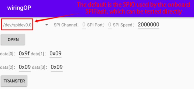
Then click the OPEN button to initialize the SPI


- Then fill in the bytes that need to be sent, such as reading the ID information of the onboard SPIFlash, filling in the address 0x9f in data[0], and then click the TRANSFER button

- Finally, the APP will display the read ID information of the onboard SPI Flash.

- If the w25qxx module connected to 40pin SPI1 is read, the ID information of the onboard SPI Flash is also similar.
40pin I2C test method
- As can be seen from the table below, the Android12 TV system has i2c1 and i2c2 turned on by default.
GPIO NO. GPIO Function Pin 3.3V 1 264 PI8 TWI1-SDA 3 263 PI7 TWI1-SCL 5 269 PI13 PWM3 7 GND 9 226 PH2 UART5_TX 11 227 PH3 UART5_RX 13 261 PI5 UART2_TX 15 3.3V 17 231 PH7 SPI1_MOSI 19 232 PH8 SPI1_MISO 21 230 PH6 SPI1_CLK 23 GND 25 266 PI10 TWI2-SDA 27 256 PI0 29 271 PI15 31 268 PI12 PWM2 33 258 PI2 35 272 PI16 37 GND 39
| Pin | Function | GPIO | GPIO NO. |
| 2 | 5V | ||
| 4 | 5V | ||
| 6 | GND | ||
| 8 | UART0_TX | PH0 | 224 |
| 10 | UART0_RX | PH1 | 225 |
| 12 | PI1 | 257 | |
| 14 | GND | ||
| 16 | PWM4 | PI14 | 270 |
| 18 | PH4 | 228 | |
| 20 | GND | ||
| 22 | UART2_RX | PI6 | 262 |
| 24 | SPI1_CS0 | PH5 | 229 |
| 26 | SPI1_CS1 | PH9 | 233 |
| 28 | TWI2-SCL | PI9 | 265 |
| 30 | GND | ||
| 32 | PWM1 | PI11 | 267 |
| 34 | GND | ||
| 36 | PC12 | 76 | |
| 38 | PI4 | 260 | |
| 40 | PI3 | 259 |
- The device node corresponding to i2c1 is /dev/i2c-1, and the device node corresponding to i2c2 is /dev/i2c-2
|
apollo-p2:/ # ls /dev/i2c-* /dev/i2c-1 /dev/i2c-2 /dev/i2c-5 |
- First open wiringOP APP on the desktop
- Then click the I2C_TEST button to open the i2c test interface

- The i2c test interface of wiringOP is shown in the figure below

- Then click the device node selection box in the upper left corner to select the i2c you want to test

- Then connect an i2c device to the 40pin i2c pin. Here we take the ds1307 rtc module as an example.

The i2c address of the ds1307 rtc module is 0x68. After connecting the lines, we can use the i2cdetect -y 1 or i2cdetect -y 2 command on the serial port command line to check whether the i2c address of the ds1307 rtc module can be scanned. If you can see the address 0x68, it means that the ds1307 rtc module is wired correctly.
apollo-p2:/ # i2cdetect -y 1
Or
apollo-p2:/ # i2cdetect -y 2
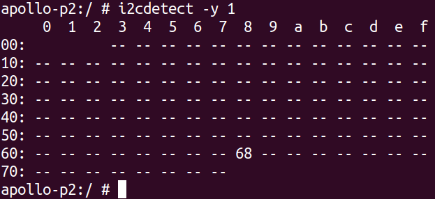
Then set the i2c address to 0x68 in wiringOP, and then click the OPEN button to open i2c
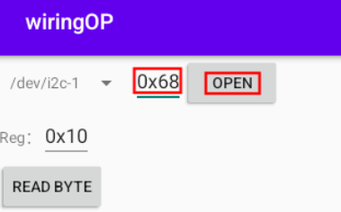
After clicking the OPEN button to open i2c, the display is as follows
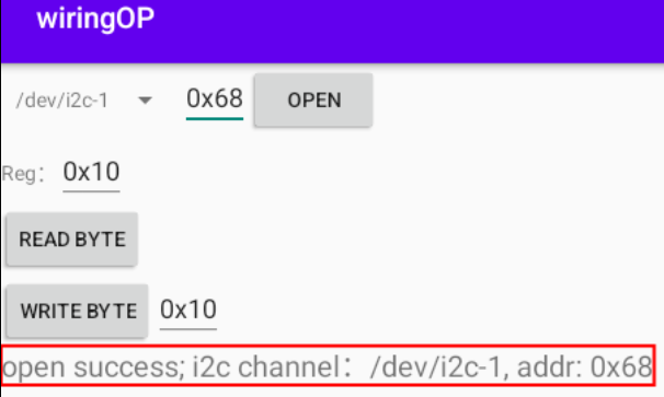
Then we test writing a value to the register of the rtc module, for example, writing 0x55 to the 0x1c address
We first set the address of the register to be written to 0x1c
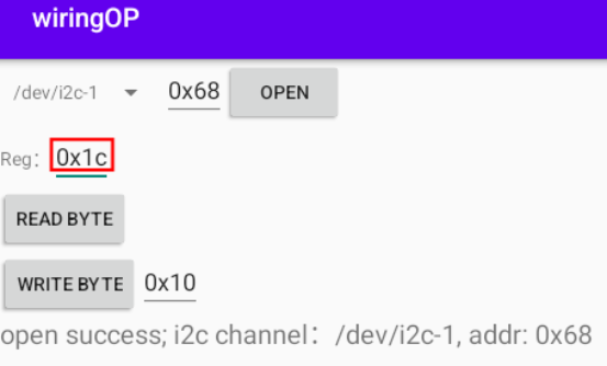
Then set the value to be written to 0x55
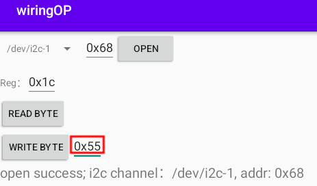
Then click the WRITE BYTE button to perform the writing action
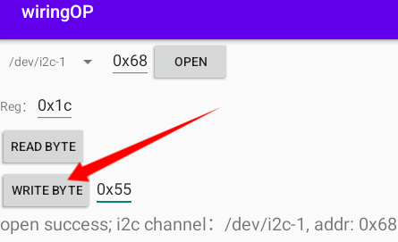
Then click the READ BYTE button to read the value of the 0x1c register. If it displays 0x55, it means that the i2c read and write test has passed.
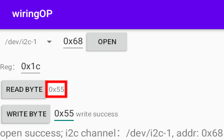


40pin PWM test
- As can be seen from the table below, the available pwm are pwm1, pwm2, pwm3 and pwm4.
GPIO NO. GPIO Function Pin 3.3V 1 264 PI8 TWI1-SDA 3 263 PI7 TWI1-SCL 5 269 PI13 PWM3 7 GND 9 226 PH2 UART5_TX 11 227 PH3 UART5_RX 13 261 PI5 UART2_TX 15 3.3V 17 231 PH7 SPI1_MOSI 19 232 PH8 SPI1_MISO 21 230 PH6 SPI1_CLK 23 GND 25 266 PI10 TWI2-SDA 27 256 PI0 29 271 PI15 31 268 PI12 PWM2 33 258 PI2 35 272 PI16 37 GND 39
| Pin | Function | GPIO | GPIO NO. |
| 2 | 5V | ||
| 4 | 5V | ||
| 6 | GND | ||
| 8 | UART0_TX | PH0 | 224 |
| 10 | UART0_RX | PH1 | 225 |
| 12 | PI1 | 257 | |
| 14 | GND | ||
| 16 | PWM4 | PI14 | 270 |
| 18 | PH4 | 228 | |
| 20 | GND | ||
| 22 | UART2_RX | PI6 | 262 |
| 24 | SPI1_CS0 | PH5 | 229 |
| 26 | SPI1_CS1 | PH9 | 233 |
| 28 | TWI2-SCL | PI9 | 265 |
| 30 | GND | ||
| 32 | PWM1 | PI11 | 267 |
| 34 | GND | ||
| 36 | PC12 | 76 | |
| 38 | PI4 | 260 | |
| 40 | PI3 | 259 |
- First click the wiringOP icon to open wiringOP APP
- Then click the PWM_TEST button on the main interface of wiringOP to enter the PWM test interface

- The PWM test interface is as follows

- Then set which PWM you want to use in the Channel. The default is PWM1. If you want to set it to PWM2, just enter 2 in the Channel. PWM3 and PWM4 and so on.

- Then you can set the PWM period. The default configuration is 50000ns. The converted PWM frequency is 20KHz

- Then click the EXPORTbutton to export PWM

- Then drag the progress bar below to change the PWM duty cycle, and then check Enable to output the PWM waveform.

- Then use an oscilloscope to measure the corresponding pins in the 40pin development board and you can see the following waveform.

How to compile Android 12 source code
Download the source code of Android 12
First download the compressed package of the Android 12 source code and the compressed package of the files modified by Orange Pi Zero2w from Google Cloud Drive
- Google Cloud Drive
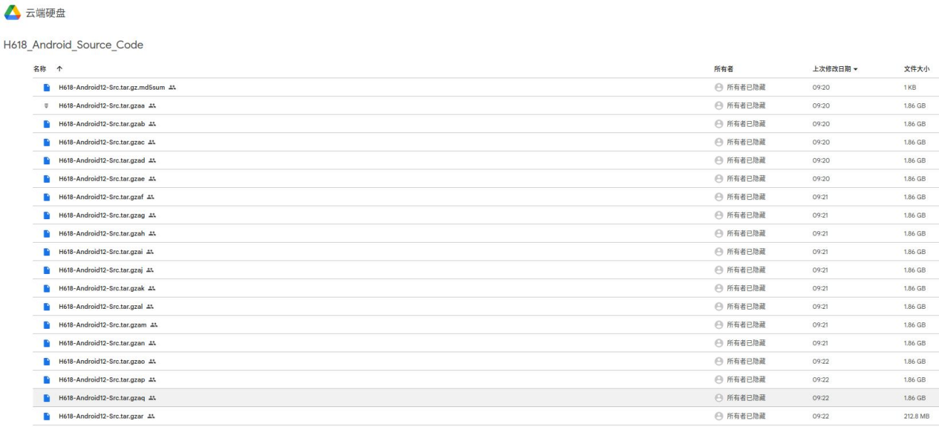

- After downloading the compressed package of Android 12 source code, please check whether the MD5 checksum is correct. If it is incorrect, please download the source code again. Here's how to check the MD5 checksum:
|
test@test:~$ md5sum -c H618-Android12-Src.tar.gz.md5sum H618-Android12-Src.tar.gzaa: OK H618-Android12-Src.tar.gzab: OK ...... |
- Then you need to merge multiple compressed files into one, and then extract the Android source code. The command looks like this:
|
test@test:~$ cat H618-Android12-Src.tar.gza* > H618-Android12-Src.tar.gz test@test:~$ tar -xvf H618-Android12-Src.tar.gz |
- Then unzip the compressed package of the files modified by Orange Pi Zero2w
|
test@test:~$ tar zxf opizero2w_android12_patches.tar.gz test@test:~$ ls opizero2w_android12_patches opizero2w_android12_patches.tar.gz |
- Then copy the files modified by Orange Pi Zero2w to the Android source code
|
test@test:~$ cp -rf opizero2w_android12_patches/* H618-Android12-Src/ |
Compile the source code of Android 12
|
Android12 is compiled on an x86_64 computer with Ubuntu 22.04 installed. Other versions of Ubuntu system package dependencies may have some differences. The image download address of the Ubuntu 22.04 amd64 version is as follows: https://repo.huaweicloud.com/ubuntu-releases/22.04/ubuntu-22.04.2-desktop-amd64.iso The x86_64 computer hardware configuration for compiling Android12 source code recommends a memory of 16GB or more, and a hard disk space of 200GB or more is recommended. The more CPU cores, the better. |
- First install the software packages needed to compile Android12 source code
test@test:~$ sudo apt-get update
test@test:~$ sudo apt-get install -y git gnupg flex bison gperf build-essential \
zip curl zlib1g-dev gcc-multilib g++-multilib libc6-dev-i386 \
lib32ncurses5-dev x11proto-core-dev libx11-dev lib32z1-dev ccache \
libgl1-mesa-dev libxml2-utils xsltproc unzip u-boot-tools python-is-python3 \
libssl-dev libncurses5 clang gawk
Then compile the code in the longan folder, which mainly contains u-boot and linux kernel
- First run ./build.sh config to set compilation options
0. android
1. linux
0. h618
0. ft
1. p1
2. p2
3. p7
4. p7l
5. perf1
6. perf2
7. perf3
8. qa
0. default
1. nor
0. linux-5.4
0. arm
1. arm64
test@test:~$ cd H618-Android12-Src/longan
test@test:~/H618-Android12-Src/longan$ ./build.sh config
Welcome to mkscript setup progress
All available platform:
Choice [android]: 0
All available ic:
Choice [h618]: 0
All available board:
Choice [p2]: 2
All available flash:
Choice [default]: 0
All available kern_ver:
Choice [linux-5.4]: 0
All available arch:
Choice [arm64]: 1
......
*** Default configuration is based on 'sun50iw9p1smp_h618_android_defconfig'
#
# configuration written to .config
#
make[1]: Leaving directory '/home/test/H618-Android12-Src/longan/out/kernel/build'
make: Leaving directory '/home/test/H618-Android12-Src/longan/kernel/linux-5.4'
INFO: clean buildserver
INFO: prepare_buildserver
- Then run the ./build.sh script to start compilation.
test@test:~/H618-Android12-Src/longan$ ./build.sh
- After compilation is completed, you will see the following output
sun50iw9p1 compile Kernel successful
INFO: Prepare toolchain ...
......
INFO: build kernel OK.
INFO: build rootfs ...
INFO: skip make rootfs for android
INFO: ----------------------------------------
INFO: build lichee OK.
INFO: ----------------------------------------
- Then use the following command to compile the Android source code and generate the final Android image
|
test@test:~$ cd H618-Android12-Src test@test:~/H618-Android12-Src$ source build/envsetup.sh test@test:~/H618-Android12-Src$ lunch apollo_p2-userdebug test@test:~/H618-Android12-Src$ make -j8 test@test:~/H618-Android12-Src$ pack |
The storage path of the Android image generated by compilation is:
longan/out/h618_android12_p2_uart0.img
Appendix
User manual update history
| Version | Date | Release Notes |
| v1.0 | 2023-09-14 | initial version |
Image update history
| Date | Release Notes |
| 2023-09-14 |
orangepizero2w_1.0.0_debian_bullseye_server_linux5.4.125.7z orangepizero2w_1.0.0_ubuntu_focal_server_linux5.4.125.7z orangepizero2w_1.0.0_ubuntu_focal_desktop_xfce_linux5.4.125.7z orangepizero2w_1.0.0_debian_bullseye_desktop_xfce_linux5.4.125.7z
orangepizero2w_1.0.0_debian_bookworm_server_linux6.1.31.7z orangepizero2w_1.0.0_debian_bullseye_server_linux6.1.31.7z orangepizero2w_1.0.0_ubuntu_jammy_desktop_xfce_linux6.1.31.7z orangepizero2w_1.0.0_debian_bookworm_desktop_xfce_linux6.1.31.7z orangepizero2w_1.0.0_debian_bullseye_desktop_xfce_linux6.1.31.7z
|