Difference between revisions of "Orange Pi Zero 2"
(→Method of flashing Linux image or OpenWRT image to TF card based on Ubuntu PC) |
(→Method of flashing Android firmware to TF card) |
||
| Line 381: | Line 381: | ||
<div style="padding-left:200px">[[File:Orange-pi-4-lts-img39.png|600px]]</div> | <div style="padding-left:200px">[[File:Orange-pi-4-lts-img39.png|600px]]</div> | ||
<br> | <br> | ||
| − | |||
| − | |||
| − | |||
| − | |||
| − | |||
| − | |||
| − | |||
| − | |||
| − | |||
| − | |||
| − | |||
| − | |||
| − | |||
| − | |||
| − | |||
| − | |||
| − | |||
| − | |||
| − | |||
| − | |||
| − | |||
| − | |||
| − | |||
| − | |||
| − | |||
| − | |||
| − | |||
| − | |||
| − | |||
| − | |||
| − | |||
| − | |||
| − | |||
| − | |||
=== ''' Start the Orange Pi development board''' === | === ''' Start the Orange Pi development board''' === | ||
Revision as of 17:01, 27 June 2022
Contents
- 1 Basic Features of Orange Pi Zero 2
- 2 Introduction to the use of the development board
- 2.1 Prepare the necessary accessories
- 2.2 Download the image of the development board and related materials
- 2.3 Method of Burning Linux Image to TF Card Based on Windows PC
- 2.4 Method of burning Linux image to TF card based on Ubuntu PC
- 2.5 Start the Orange Pi development board
- 2.6 How to use the debug serial port
Basic Features of Orange Pi Zero 2
What is Orange Pi Zero 2
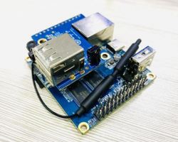
Orange Pi is an open source single-board -computer, a new generation of arm64 development boards, which can run Android TV 10, Ubuntu and Debian . The Orange Pi Zero 2 uses the Allwinner H616 Rockchip and has 1GB DDR3 .
Purpose of Orange Pi Zero 2
We can use it to build:
- A small Linux system computer
- A small Linux web server
- Install Klipper host computer to control 3D printer
- Android TV box
Of course, there are other more functions, because the Orange Pi development board can install Linux systems such as Debian and Ubuntu, and Android TV system, which means that we can implement a variety of functions within the scope of the development board hardware and software support.
Who is Orange Pi Zero 2 designed for?
Orange Pi Zero2 is for anyone who wants to start creating with technology – not just consuming it. It's a simple, fun, useful tool that you can use to start taking control of the world around you.
Hardware Features of Orange Pi Zero 2
| colspan=2 | Hardware Introduction
|
| CPU | Allwinner H616 64-bit high-performance Quad-core Cortex-A53 processor |
| GPU |
Mali G31 MP2 |
| Memory(SDRAM) | 1GB DDR3 (Shared with GPU) |
| Onboard Storage | TF card slot、2MB SPI Flash |
| Onboard Network | Support 1000M/100M/10M Ethernet |
| WIFI+BT | * AW859A Chip、Support IEEE 802.11 a/b/g/n/ac、BT5.0 |
| Video Outputs |
|
| Audio output |
|
| Power Source | USB Type C interface input |
| USB 2.0 Ports | 3*USB 2.0 HOST(Two of them are via 13pin interface board) |
| 26pin header | With I2Cx1、SPIx1、UARTx1 and multiple GPIO ports |
| 13pin header | With USB 2.0 HOSTx2、TV-OUT、LINE OUT、IR-RX、and 3*GPIO ports |
| Debug serial port | UART-TX、UART-RX and GND |
| LED | Power led & Status led |
| IR receiver | Support IR remote control (via 13pin interface board) |
| Supported OS | Android10 TV、Ubuntu、Debian and so on |
| colspan=2 | Appearance specification
|
| Dimension | 85mm×56mm |
| Weight | 30g |
| colspan=2 |
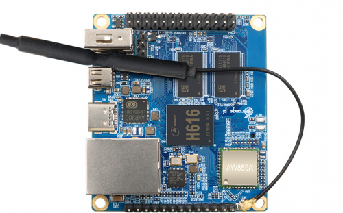
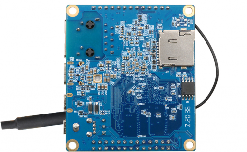
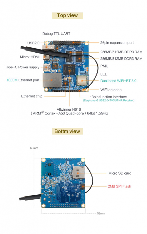
The Top view and Bottom view of Orange Pi Zero 2
Top view:
Bottom view:
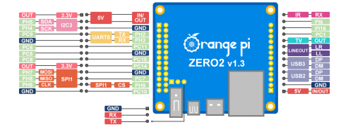
The Ports Detail of Orange Pi Zero 2
The diameter of the four positioning holes is 3.0mm
Introduction to the use of the development board
Prepare the necessary accessories
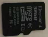
1)TF card, class10 or above high-speed SanDisk card with a minimum capacity of 8GB
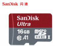
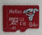
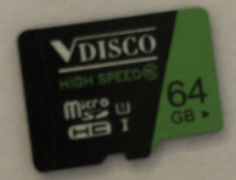
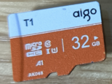
Use other brands of TF cards (not SanDisk TF cards), as shown in the picture below (including but not only to these cards), some friends have reported that there will be problems during the system startup process, such as the system being stuck halfway during startup, Or the reboot command cannot be used normally, and it was finally solved after change to using the SanDisk TF card. So if you are using a non-SanDisk TF card and find that problems during system startup or use, please replace the TF card to the SanDisk TF card and then test
In addition, the TF card that can be used normally on other types of development boards does not guarantee that the Orange Pi Zero 2 will also start normally by using this TF card. Please pay special attention to this point.
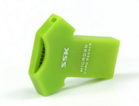
2)TF card reader, used to read and write TF card
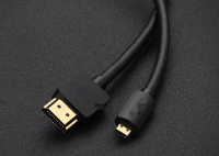
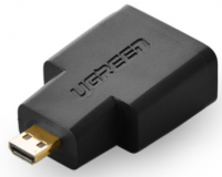
3)Micro HDMI to HDMI cable, used to connect the development board to an HDMI monitor or TV for display
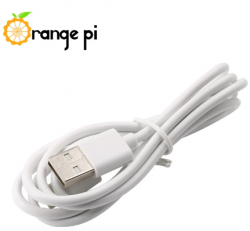
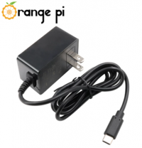
4)Power supply, if there is a 5V/2A or 5V/3A power supply head, you only need to prepare a data cable with the USB to Type C interface like as shown in the picture on the left below, and you can also use a cable similar to the picture shown on the right below. 5V/2A or 5V/3A high-quality USB Typc C interface power adapter supply
5)13pin interface board
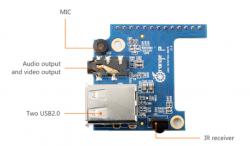
a.The actual interface board is shown below
b.The way to insert the expansion board into the development board is as follows, note: not to inserted in the wrong direction
c.The 13pin pin header on the Orange Pi Zero 2 development board can be connected to the expansion board to expand the functions that are not available on the development board. The functions that the expansion board can use include:
| 1 | Mic |
No support, no support, no support! ! ! |
| 2 | Analog audio and video output interface | Support, it can be used to connect headphones to play music, or connect to TV through AV cable to output analog audio and video signals (Android only). |
| 3 | USB2.0 Host x 2 | Supported, used to connect USB keyboard, mouse and USB storage device. |
| 4 | IR function | Support, can control Android system through infrared remote control |
d.The schematic diagram about the 13pin pin header of the Orange Pi Zero 2 development board is as follows
6)USB interface mouse and keyboard, as long as it is a standard USB interface mouse and keyboard, the mouse and keyboard can be used to control the Orange Pi development board
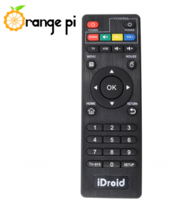
7)Infrared remote control, mainly used to control the Android system
8)Fast or Gigabit Ethernet cable to connect the development board to the Internet
9)AV video cable, if you want to display video through the AV interface instead of the HDMI interface, then you need to connect the development board to the TV through the AV video cable
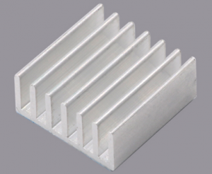
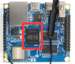
10)Heat sink, if you are worried that the temperature of the development board is too high, you can add a heat sink, and the heat sink can be attached to the H616 chip
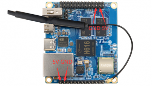
11)5V cooling fan, as shown in the figure below, there are 5V and GND pins on the 26pin and 13pin interfaces of the development board that can be connected to the cooling fan. The distance between the 26pin and 13pin pin headers is 2.54mm, and the power interface of the cooling fan refers to this Specifications to buy
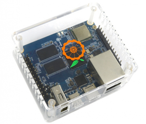
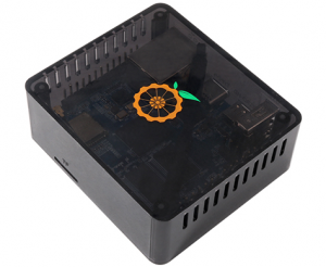
12)Matching shell, transparent shell and black shell are available
Note that the matching case of the Orange Pi Zero 2 cannot hold the 13pin expansion board.
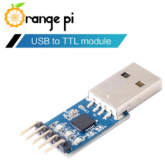
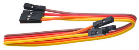
13)USB to TTL module and DuPont cable, when using the serial port debugging function, USB to TTL module and DuPont cable are required to connect the development board and computer
Note that the TTL level used by the development board is 3.3v. Except for the USB to TTL module shown in the figure above, other similar 3.3v USB to TTL modules are generally available.
14)A PC with Ubuntu and Windows operating systems installed
| 1 | Ubuntu14.04.6 PC | Optional, used to compile Android source code |
| 2 | Ubuntu18.04 PC | Optional, used to compile Linux source code |
| 3 | Windows PC | For burning Android and Linux images |
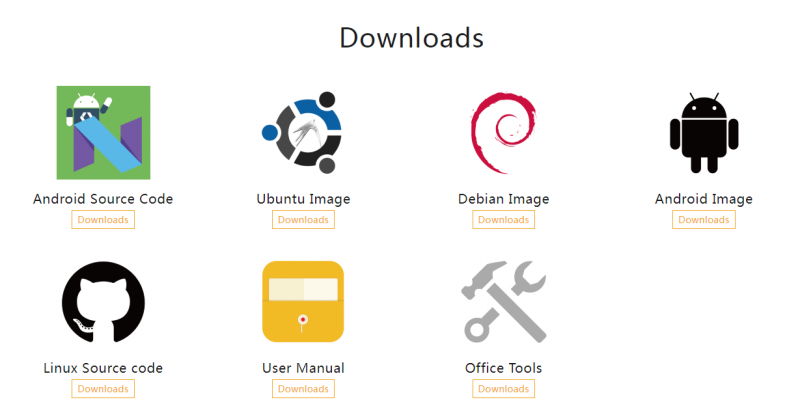
1)The download URL of the English version of the material is:
http://www.orangepi.org/html/hardWare/computerAndMicrocontrollers/service-and-support/Orange-Pi-Zero-2.html
2)The data mainly includes
a.Android source code:Save on Google network disk
b.Linux source code:Save on Github
c.User Manual and Schematics:Chip related data sheets will also be placed here
d.Official tool: Mainly includes the software that needs to be used in the use of the development board
e.Android Image:Save on Google network disk
f.Ubuntu Image:Save on Google network disk
g.Debian Image:Save on Google network disk
Method of Burning Linux Image to TF Card Based on Windows PC
Note that the Linux image mentioned here refers specifically to the image of a Linux distribution such as Debian or Ubuntu downloaded from the Orange Pi data download page.
The way to use balenaEtcher to burn a Linux image
1)First prepare a TF card with a capacity of 8GB or more. The transmission speed of the TF card must be class10 or above. It is recommended to use a TF card from a brand such as SanDisk
2)Then insert the TF card into the card reader and insert it into the computer
3)Download the compressed package of the Linux operating system image file you want to burn from the data download page of Orange Pi, and then use the decompression software to decompress it. In the decompressed file, the file ending with ".img" is the image file of the operating system. It is generally more than 1GB
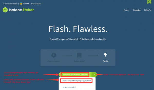
4)Then download the burning software for the Linux image——balenaEtcher,the download address is
https://www.balena.io/etcher/
5)After entering the balenaEtcher download page, click the green download button to download the installation package of balenaEtcher, or select the Portable version of balenaEtcher through the drop-down button. The Portable version does not need to be installed, just double-click to open it and use it
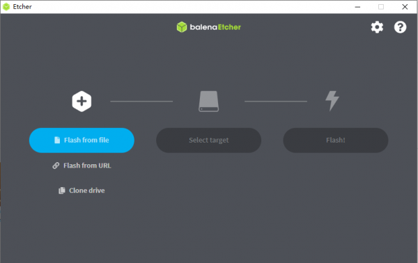
6)If you download a version of balenaEtcher that needs to be installed, please install it before using it. If you download the Portable version of balenaEtcher, just double-click to open it. The opened balenaEtcher interface is shown in the figure below.
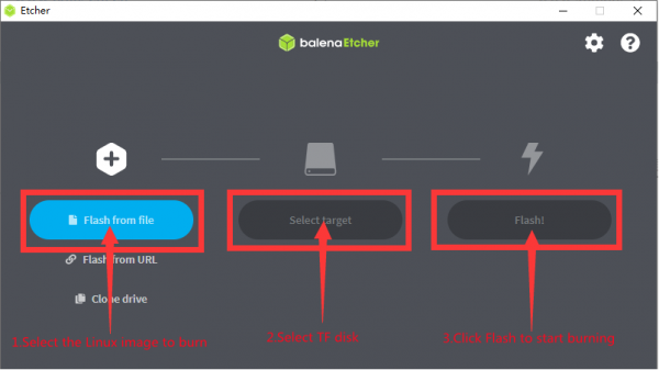
7)The specific steps to use balenaEtcher to burn a Linux image are as follows
a.First select the path of the Linux image file to be burned
b.Then select the symbol of the TF card
c.Finally, click Flash to start burning the Linux image to the TF card
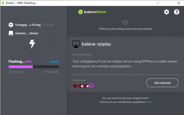
8)The interface displayed in the process of balenaEtcher burning the Linux image is shown in the figure below. In addition, the progress bar shows purple to indicate that the Linux image is being burned to the TF card.
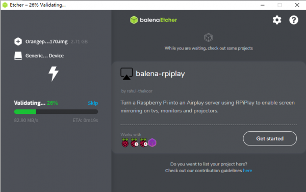
9)After the Linux image is burned, balenaEtcher will also verify the image burned to the TF card by default to ensure that there is no problem in the burning process. As shown in the figure below, a green progress bar indicates that the image has been burned, and balenaEtcher is verifying the burned image.
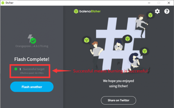
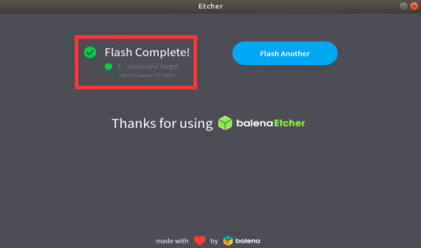
10)After the successful burning, the display interface of balenaEtcher is shown in the figure below. If the green indicator icon is displayed, it means that the image burning is successful. At this time, you can exit balenaEtcher, and then pull out the TF card and insert it into the TF card slot of the development board.
The Way to use Win32Diskimager to burn Linux image
1)First prepare a TF card with a capacity of 8GB or more. The transmission speed of the TF card must be above class 10. It is recommended to use a TF card from a brand such as SanDisk
2)Then use the card reader to insert the TF card into the computer
3)Then format the TF card
a.The SD Card Formatter software can be used to format the TF card, and its download address is
https://www.sdcard.org/downloads/formatter/eula_windows/SDCardFormatterv5_WinEN.zip
b.After downloading, unzip and install directly, and then open the software
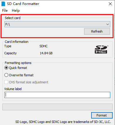
c.If only the TF card is inserted into the computer, the “Select card” column will display the drive letter of the TF card. If multiple USB storage devices are inserted into the computer, you can select the drive letter corresponding to the TF card through the drop-down box.
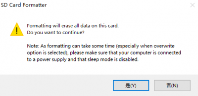
d.Then click "Format", a warning box will pop up before formatting, select "Yes (Y)" to start formatting
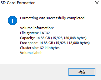
e.After formatting the TF card, the information shown in the figure below will pop up, click OK.
4)Download the compressed package of the Linux operating system image file you want to burn from the data download page of Orange Pi, and then use the decompression software to decompress it. In the decompressed file, the file ending with ".img" is the image file of the operating system. The size is generally more than 1GB
5)Use Win32Diskimager to burn the Linux image to the TF card
a.The download page of Win32Diskimager is
http://sourceforge.net/projects/win32diskimager/files/Archive/
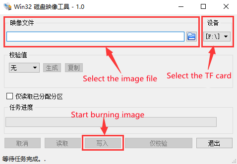
b.After downloading, install it directly. The Win32Diskimager interface is as follows
a) First select the path of the image file
b) Then confirm that the drive letter of the TF card is consistent with the one displayed in the "Device" column
c) Finally click "Write" to start burning
c.After the image writing is completed, click the "Exit" button to exit, and then you can pull out the TF card and insert it into the development board to start
Method of burning Linux image to TF card based on Ubuntu PC
Note that the Linux image mentioned here specifically refers to a Linux distribution image such as Debian or Ubuntu downloaded from the Orange Pi data download page, and Ubuntu PC refers to a personal computer with Ubuntu installed.
1)First prepare a TF card with 8GB or more. The transmission speed of the TF card must be class10 or above. It is recommended to use a TF card from a brand such as SanDisk
2)Then use the card reader to insert the TF card into the computer
3)Download balenaEtcher software, the download address is
https://www.balena.io/etcher/
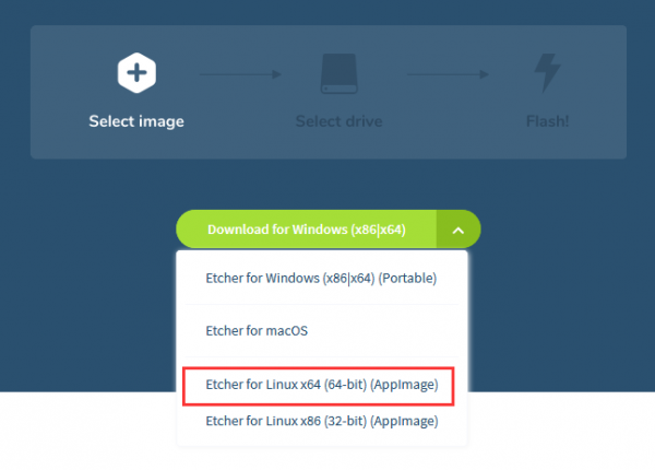
4)After entering the balenaEtcher download page, please select the Linux version of the software through the drop-down box to download
5)After downloading, use unzip to decompress. The decompressed balenaEtcher-1.5.109-x64.AppImage is the software needed to burn Linux image
test@test:~$ unzip balena-etcher-electron-1.5.109-linux-x64.zip
Archive: balena-etcher-electron-1.5.109-linux-x64.zip
inflating: balenaEtcher-1.5.109-x64.AppImage
test@test:~$ ls
balenaEtcher-1.5.109-x64.AppImage balena-etcher-electron-1.5.109-linux-x64.zip
6)Download the compressed package of the Linux operating system image file you want to burn from the data download page of Orange Pi, and then use the decompression software to decompress it. In the decompressed file, the file ending with ".img" is the image file of the operating system. It is generally more than 1GB
The decompression command for the compressed Documentation ending in 7z is as follows
test@test:~$ 7z x Orangepizero2_2.2.0_ubuntu_focal_desktop_linux4.9.170.7z
test@test:~$ ls Orangepizero2_2.2.0_ubuntu_focal_desktop_linux4.9.170.*
Orangepizero2_2.2.0_ubuntu_focal_desktop_linux4.9.170.7z
Orangepizero2_2.2.0_ubuntu_focal_desktop_linux4.9.170.sha #checksum file
Orangepizero2_2.2.0_ubuntu_focal_desktop_linux4.9.170.img #image file
7)After decompressing the image, you can use the sha256sum -c *.sha command to calculate whether the checksum is correct. If the message is successful, it means that the downloaded image is correct. You can safely burn it to the TF card. If the checksum does not match, it means that There is a problem with the downloaded image, please try to download again
test@test:~$ sha256sum -c *.sha
orangepizero2_2.2.0_ubuntu_bionic_server_linux4.9.170.img: success
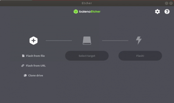
8)Then double-click balenaEtcher-1.5.109-x64.AppImage on the graphical interface of Ubuntu PC to open balenaEtcher (no installation required), and the interface after balenaEtcher is opened is shown in the following figure
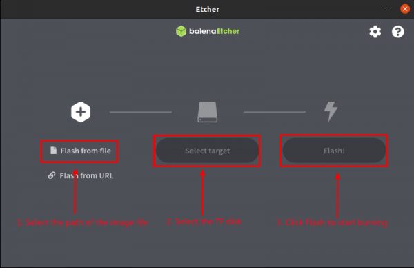
9)The specific steps to use balenaEtcher to burn a Linux image are as follows
a.First select the path of the Linux image file to be burned
b.Then select the symbol of the TF card
c.Finally, click Flash to start burning the Linux image to the TF card
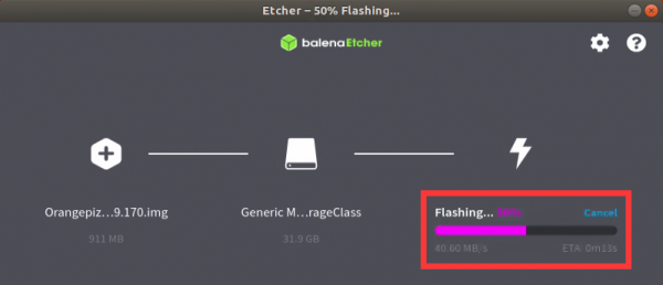
10)The interface displayed in the process of balenaEtcher burning the Linux image is shown in the figure below. In addition, the progress bar shows purple to indicate that the Linux image is being burned to the TF card.
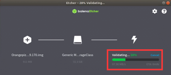
11)After the Linux image is burned, balenaEtcher will also verify the image burned to the TF card by default to ensure that there is no problem in the burning process. As shown in the figure below, a green progress bar indicates that the image has been burned, and balenaEtcher is verifying the burned image.
12)After the successful burning, the display interface of balenaEtcher is shown in the figure below. If the green indicator icon is displayed, it means that the image burning is successful. At this time, you can exit balenaEtcher, and then pull out the TF card and insert it into the TF card slot of the development board.
Start the Orange Pi development board
1)Insert the burned TF card into the TF card slot of the Orange Pi development board
2) The development board has an Ethernet port, which can be plugged into a network cable for Internet access
3)Connect a 5V/2A (5V/3A is also available) high-quality power adapter
a.Remember not to plug in the 12V power adapter, if you plug in the 12V power adapter, it will burn the development board
b.Many unstable phenomena during system power-on and startup are basically caused by power supply problems, so a reliable power adapter is very important
4)If you want to view the output information of the system through the debug serial port, please use the USB to TTL module and DuPont cable to connect the development board to the computer. For the connection method of the serial port, please refer to the section on the use of the debug serial port
5)Then turn on the switch of the power adapter, if everything is normal, the serial terminal can see the output log of the system startup at this time
How to use the debug serial port
Debug serial port connection instructions
1)First, you need to prepare a USB to TTL module. This module can be bought in Orange Pi Store. If there are other similar USB to TTL modules, you can also insert the USB port of the USB to TTL module into the USB of the computer Interface
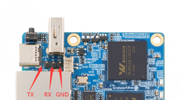
2)The corresponding relationship between the debug serial port GND, TX and RX pins of the development board is shown in the figure below
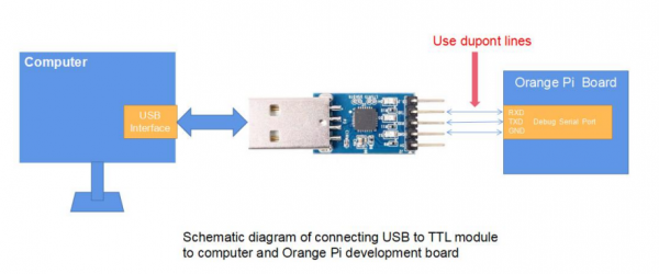
3)The GND, TX and RX pins of the USB to TTL module need to be connected to the debug serial port of the development board through a Dupont cable
a. Connect the GND of the USB to TTL module to the GND of the development board
b. Connect the RX of the USB to TTL module to the TX of the development board
c. Connect the TX of the USB to TTL module to the RX of the development board
4)The schematic diagram of connecting the USB to TTL module to the computer and the Orange Pi development board is shown below
5)If you are using a CP2102 USB to TTL module, under the condition of a baud rate of 1.500000, some systems may encounter garbled or unusable problems. The specific test situation is as follows
| USB to TTL module model | Host system | Support situation |
| CH340 | win7 | ok |
| win10 | ok | |
| ubuntu14.04 | ok | |
| ubuntu18.04 | ok | |
| ubuntu20.04 | ok | |
| CP2102 | win7 | ok |
| win10 | Not available | |
| ubuntu14.04 | ok | |
| ubuntu18.04 | Not available | |
| ubuntu20.04 | Not available |
How to use the debugging serial port on Ubuntu platform
1)If the USB to TTL module is connected normally, you can see the corresponding device node name under /dev of the Ubuntu PC, remember this node name, it will be used when setting the serial port software later
test@test:~$ ls /dev/ttyUSB*
/dev/ttyUSB0
2)There are many serial debugging tools that can be used under linux, such as putty, minicom, etc. The following demonstrates how to use putty
3)First install putty on the Ubuntu PC
test@test:~$ sudo apt update
test@test:~$ sudo apt -y install putty
4)Then run putty, remember to add sudo permissions
test@test:~$ sudo putty
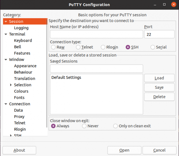
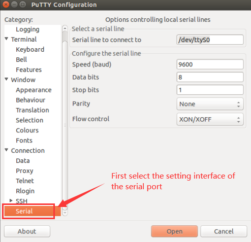
5)After executing the putty command, the following interface will pop up
6)First select the setting interface of the serial port
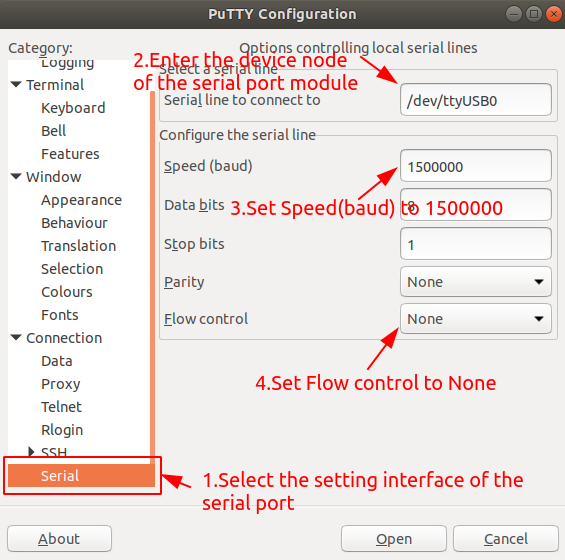
7)Then set the parameters of the serial port
a. Set the Serial line to connect to to /dev/ttyUSB0 (modify to the corresponding node name, generally /dev/ttyUSB0)
b. Set Speed (baud) to 1500000 (baud rate of the serial port)
c. Set Flow control to None
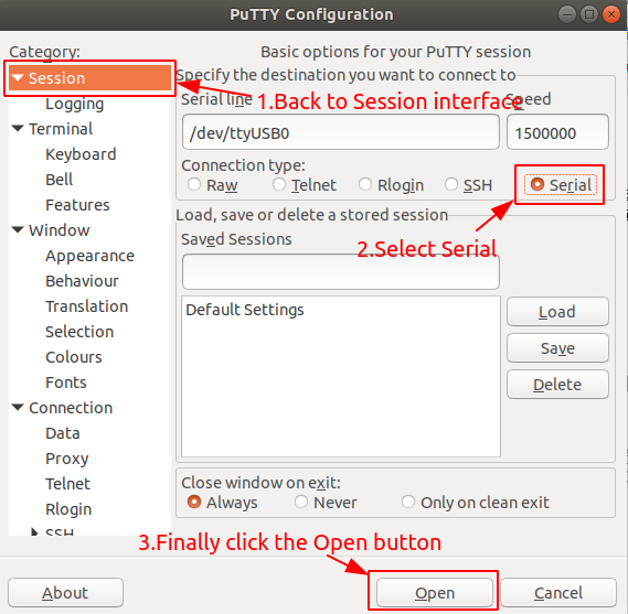
8)After setting the serial port setting interface, return to the Session interface
a. First select the Connection type as Serial
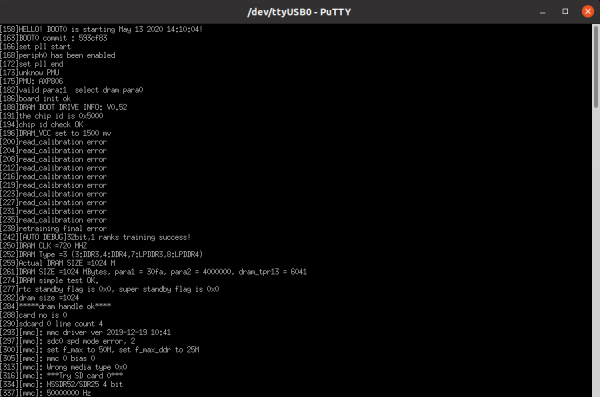
9)After starting the development board, you can see the Log information output by the system from the opened serial port terminal
How to use the debugging serial port on Windows platform
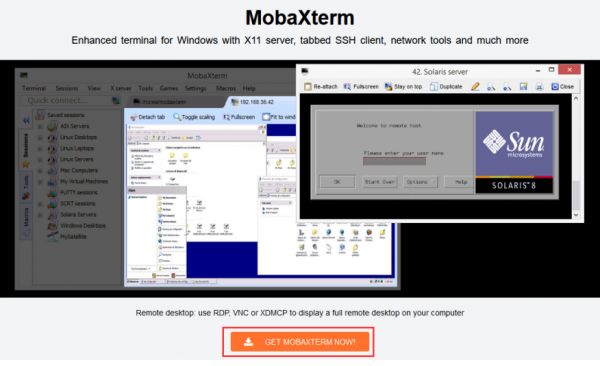
1)There are many serial debugging tools that can be used under Windows, such as SecureCRT, MobaXterm, etc. The following shows how to use MobaXterm. This software is free and can be used without purchasing a serial number.
2)Download MobaXterm
a.Download the MobaXterm URL as follows
https://mobaxterm.mobatek.net/
b.After entering the MobaXterm download page, click GET XOBATERM NOW!
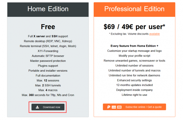
c.Then choose to download the Home version
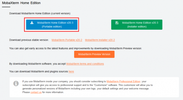
d.Then select the Portable version, after downloading, you don’t need to install it, just open it and you can use it
3)After downloading, use the decompression software to decompress the downloaded compressed package, you can get the executable software of MobaXterm, and then double-click to open it
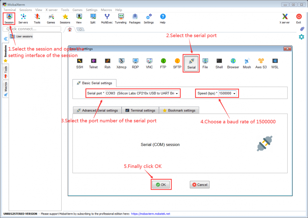
4)After opening the software, the steps to set up the serial port connection are as follows
a. Open the session setting interface
b. Select the serial port type
c. Select the port number of the serial port (choose the corresponding port number according to the actual situation), if you can't see the port number, please use the 360 driver master to scan and install the USB to TTL serial chip driver
d. Select the baud rate of the serial port to be 1500000
e. Finally click the "OK" button to complete the setting
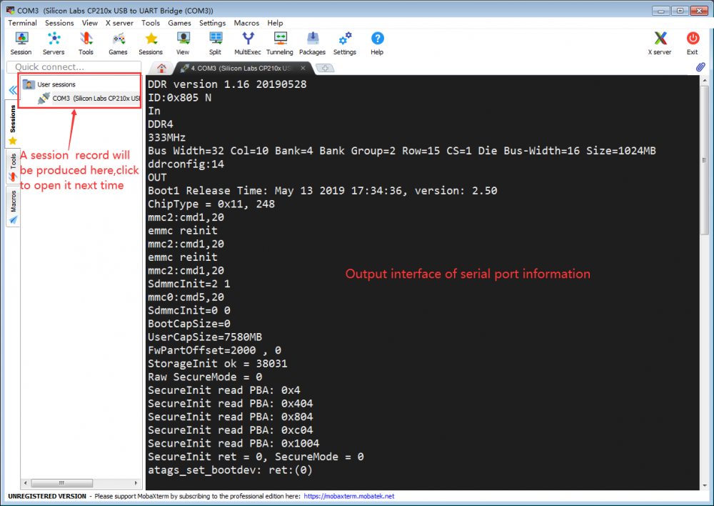
5)After clicking the "OK" button, you will enter the following interface, and you can see the output information of the serial port when you start the development board.
For more information on using the Orange Pi R1 Plus LTS, please see the Orange Pi R1 Plus LTS User Manual. (Click to download)
