8,367
edits
Changes
Created page with "1) Please refer to the figure below for the order of the 26 pin interface pins on the Orange Pi 5 development board<br><br> Image:Pi-5-details2-pic17.png<br><br> 2) The fu..."
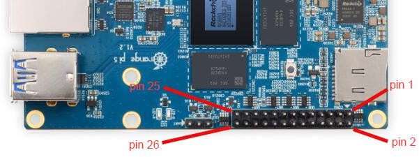
1) Please refer to the figure below for the order of the 26 pin interface pins on the Orange Pi 5 development board<br><br>
[[Image:Pi-5-details2-pic17.png]]<br><br>
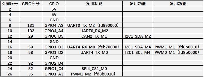
2) The functions of the 26 pin interface pins on the Orange Pi 5 development board are shown in the table below<br>
a. The following is the complete pin diagram of 26pin<br><br>
[[Image:Pi-5-details2-pic18.png]]<br><br>
b. The table below is the picture of the left half of the complete table above, so you can see it clearly<br><br>
[[Image:Pi-5-details2-pic19.png]]<br><br>
c. The table below is the picture of the right half of the complete table above, so you can see it clearly<br><br>
[[Image:Pi-5-details2-pic20.png]]<br><br>
{| class="wikitable" style="background-color:#ffffdc;width:800px;"
|-
| <br><big>'''The pwm in the above table has marked the base address of the corresponding register, which is useful when checking which pwmchip in /sys/class/pwm/ corresponds to which pwm pin in the 26pin header.'''</big><br><br>
|}
3) There are a total of 17 GPIO ports in the 26pin interface, and the voltage of all GPIO ports is '''<span style="color:#FF0000">3.3v</span>'''<br><br>