Difference between revisions of "Orange Pi CM4"
(Created page with "= Basic features of Orange Pi CM4 = <span id="what-is-orange-pi-cm4"></span> == What is Orange Pi CM4 == Orange Pi CM4 uses Rockchip RK3566 quad-core 64-bit Cortex-A55 proce...") |
(→Download orangepi-build from github) |
||
| (229 intermediate revisions by the same user not shown) | |||
| Line 1: | Line 1: | ||
| − | = Basic features of Orange Pi CM4 = | + | = '''Basic features of Orange Pi CM4''' = |
<span id="what-is-orange-pi-cm4"></span> | <span id="what-is-orange-pi-cm4"></span> | ||
| Line 20: | Line 20: | ||
* Android game console, etc. | * Android game console, etc. | ||
| − | '''Of course, there are more functions. Relying on a powerful ecosystem and a variety of expansion accessories, Orange Pi can help users easily achieve delivery from ideas to prototypes to mass production. It is an ideal choice for makers, dreamers, and hobbyists. An ideal creative platform for readers.''' | + | {| class="wikitable" style="background-color:#ffffdc;width:800px;" |
| + | |- | ||
| + | | | ||
| + | <big>'''Of course, there are more functions. Relying on a powerful ecosystem and a variety of expansion accessories, Orange Pi can help users easily achieve delivery from ideas to prototypes to mass production. It is an ideal choice for makers, dreamers, and hobbyists. An ideal creative platform for readers.'''</big> | ||
| + | |} | ||
<span id="hardware-specifications-of-orange-pi-cm4"></span> | <span id="hardware-specifications-of-orange-pi-cm4"></span> | ||
| + | |||
== Hardware specifications of Orange Pi CM4 == | == Hardware specifications of Orange Pi CM4 == | ||
| Line 28: | Line 33: | ||
=== Hardware specifications of Orange Pi CM4 core board === | === Hardware specifications of Orange Pi CM4 core board === | ||
| − | {| class="wikitable" | + | {| class="wikitable" style="width:800px;" |
|- | |- | ||
| − | | '''Hardware | + | | colspan=2| |
| − | + | <div style="text-align:center"><big>'''Hardware specifications'''</big></div> | |
|- | |- | ||
| − | | Master chip | + | | style="width:150px;" | Master chip |
| − | | Rockchip RK3566 | + | | |
| + | Rockchip RK3566 | ||
|- | |- | ||
| CPU | | CPU | ||
| − | | Quad-core 64-bit Cortex-A55 processor, 22nm advanced process, clocked at up to 1.8GHz | + | | |
| + | Quad-core 64-bit Cortex-A55 processor, 22nm advanced process, clocked at up to 1.8GHz | ||
|- | |- | ||
| GPU | | GPU | ||
| − | | • ARM Mali G52 2EE graphics processor | + | | |
| + | • ARM Mali G52 2EE graphics processor | ||
• Support OpenGL ES 1.1/2.0/3.2, OpenCL 2.0, Vulkan 1.1 | • Support OpenGL ES 1.1/2.0/3.2, OpenCL 2.0, Vulkan 1.1 | ||
| Line 48: | Line 56: | ||
|- | |- | ||
| NPU | | NPU | ||
| − | | •Integrated RKNN NPU AI accelerator, 0.8Tops@INT8 performance | + | | |
| + | •Integrated RKNN NPU AI accelerator, 0.8Tops@INT8 performance | ||
•Supports one-click conversion of Caffe/TensorFlow/TFLite/ONNX/PyTorch/Keras/Darknet architecture models | •Supports one-click conversion of Caffe/TensorFlow/TFLite/ONNX/PyTorch/Keras/Darknet architecture models | ||
| Line 54: | Line 63: | ||
|- | |- | ||
| VPU | | VPU | ||
| − | | • 4K@60fps H.265/H.264/VP9 video decoding | + | | |
| + | • 4K@60fps H.265/H.264/VP9 video decoding | ||
• 1080P@60fps H.265/H.264 video encoding | • 1080P@60fps H.265/H.264 video encoding | ||
| Line 60: | Line 70: | ||
|- | |- | ||
| PMU | | PMU | ||
| − | | Rockchip RK809-5 | + | | |
| + | Rockchip RK809-5 | ||
|- | |- | ||
| Memory | | Memory | ||
| − | | 2GB/4GB/8GB (LPDDR4/4x) | + | | |
| + | 2GB/4GB/8GB (LPDDR4/4x) | ||
|- | |- | ||
| Storage | | Storage | ||
| − | | • Onboard eMMC: 16GB/32GB/64GB/128GB | + | | |
| + | • Onboard eMMC: 16GB/32GB/64GB/128GB | ||
• SPI Flash: default blank paste | • SPI Flash: default blank paste | ||
| Line 72: | Line 85: | ||
|- | |- | ||
| Wi-Fi+BT | | Wi-Fi+BT | ||
| − | | Wi-Fi 5+BT 5.0, BLE(AP6256) | + | | |
| + | Wi-Fi 5+BT 5.0, BLE(AP6256) | ||
|- | |- | ||
| Ethernet transceiver | | Ethernet transceiver | ||
| − | | 10/100/1000Mbps Ethernet (onboard PHY chip: YT8531C) | + | | |
| + | 10/100/1000Mbps Ethernet (onboard PHY chip: YT8531C) | ||
|- | |- | ||
| Core board interface | | Core board interface | ||
| − | | 2 x 100PIN, 1 x 24PIN, including the following signals: | + | | |
| + | 2 x 100PIN, 1 x 24PIN, including the following signals: | ||
• 10/100/1000Mbps Ethernet MDI signal | • 10/100/1000Mbps Ethernet MDI signal | ||
| − | • 1x HDMI 2.0 interface, up to 4K@60fps | + | • 1x HDMI 2.0 interface, up to 4K@60fps |
| + | |||
• 1x 4-lane MIPI DSI display interface | • 1x 4-lane MIPI DSI display interface | ||
| Line 103: | Line 120: | ||
|- | |- | ||
| Supported OS | | Supported OS | ||
| − | | Android11, Ubuntu22.04, Ubuntu20.04, Debian11, Debian12, open source Hongmeng 4.0 Beta1, Orange Pi OS (Arch), Orange Pi OS (OH) based on open source Hongmeng and other operating systems. | + | | |
| + | Android11, Ubuntu22.04, Ubuntu20.04, Debian11, Debian12, open source Hongmeng 4.0 Beta1, Orange Pi OS (Arch), Orange Pi OS (OH) based on open source Hongmeng and other operating systems. | ||
|- | |- | ||
| − | | Introduction of Appearance Specifications | + | | colspan=2| |
| − | + | <div style="text-align:center"><big>'''Introduction of Appearance Specifications'''</big></div> | |
|- | |- | ||
| PCB Size | | PCB Size | ||
| − | | 55x40mm | + | | |
| + | 55x40mm | ||
|} | |} | ||
<span id="hardware-specifications-of-orange-pi-cm4-baseboard"></span> | <span id="hardware-specifications-of-orange-pi-cm4-baseboard"></span> | ||
| + | |||
=== Hardware specifications of Orange Pi CM4 baseboard === | === Hardware specifications of Orange Pi CM4 baseboard === | ||
| − | {| class="wikitable" | + | {| class="wikitable" style="width:800px;" |
|- | |- | ||
| − | | '''CM4 Base Board Hardware Specifications''' | + | | colspan=2| |
| − | + | <div style="text-align:center"><big>'''CM4 Base Board Hardware Specifications'''</big></div> | |
|- | |- | ||
| Storage | | Storage | ||
| − | | • M.2 M-KEY slot: SATA3 or PCIe2.0 NVME SSD | + | | |
| + | • M.2 M-KEY slot: SATA3 or PCIe2.0 NVME SSD | ||
• TF card slot | • TF card slot | ||
| Line 127: | Line 148: | ||
|- | |- | ||
| Ethernet interface | | Ethernet interface | ||
| − | | 10/100/1000Mbps Ethernet RJ45 socket | + | | |
| + | 10/100/1000Mbps Ethernet RJ45 socket | ||
|- | |- | ||
| Display | | Display | ||
| − | | • 1x Micro HDMI TX 2.0, maximum support 4K@60FPS | + | | |
| + | • 1x Micro HDMI TX 2.0, maximum support 4K@60FPS | ||
• 1xMIPI DSI 2 Lane | • 1xMIPI DSI 2 Lane | ||
| Line 138: | Line 161: | ||
|- | |- | ||
| Camera | | Camera | ||
| − | | 2xMIPI CSI 2 Lane | + | | |
| + | 2xMIPI CSI 2 Lane | ||
|- | |- | ||
| USB | | USB | ||
| − | | • 1xUSB 2.0 supports Device or HOST mode | + | | |
| + | • 1xUSB 2.0 supports Device or HOST mode | ||
• 1xUSB 3.0 HOST | • 1xUSB 3.0 HOST | ||
| Line 149: | Line 174: | ||
|- | |- | ||
| Audio | | Audio | ||
| − | | 3.5mm headphone jack audio input/output | + | | |
| + | 3.5mm headphone jack audio input/output | ||
|- | |- | ||
| Button | | Button | ||
| − | | 1xMaskROM key, 1xRECOVERY key, 1x reset key | + | | |
| + | 1xMaskROM key, 1xRECOVERY key, 1x reset key | ||
|- | |- | ||
| FAN | | FAN | ||
| − | | 4Pin 2.54mm 5V fan interface | + | | |
| + | 4Pin 2.54mm 5V fan interface | ||
|- | |- | ||
| 40Pin | | 40Pin | ||
| − | | 40Pin function expansion interface, supports the following interface types: | + | | |
| + | 40Pin function expansion interface, supports the following interface types: | ||
GPIO、UART、I2C、SPI、PWM | GPIO、UART、I2C、SPI、PWM | ||
| Line 164: | Line 193: | ||
|- | |- | ||
| Power Source | | Power Source | ||
| − | | Type-C 5V3A | + | | |
| + | Type-C 5V3A | ||
|- | |- | ||
| Supported OS | | Supported OS | ||
| − | | Android11, Ubuntu22.04, Ubuntu20.04, Debian11, Debian12, open source Hongmeng 4.0 Beta1, Orange Pi OS (Arch), Orange Pi OS (OH) based on open source Hongmeng and other operating systems. | + | | |
| + | Android11, Ubuntu22.04, Ubuntu20.04, Debian11, Debian12, open source Hongmeng 4.0 Beta1, Orange Pi OS (Arch), Orange Pi OS (OH) based on open source Hongmeng and other operating systems. | ||
|- | |- | ||
| − | | '''Introduction of Appearance Specifications''' | + | | colspan=2| |
| − | + | <div style="text-align:center"><big>'''Introduction of Appearance Specifications'''</big></div> | |
|- | |- | ||
| − | | PCB Size | + | | style="width:150px;" | PCB Size |
| − | | 85x56mm | + | | |
| + | 85x56mm | ||
|} | |} | ||
<span id="top-view-and-bottom-view-of-orange-pi-cm4"></span> | <span id="top-view-and-bottom-view-of-orange-pi-cm4"></span> | ||
| + | |||
== Top view and bottom view of Orange Pi CM4 == | == Top view and bottom view of Orange Pi CM4 == | ||
| Line 182: | Line 215: | ||
=== Top view and bottom view of Orange Pi CM4 core board === | === Top view and bottom view of Orange Pi CM4 core board === | ||
| − | '''Top view:''' | + | <big>'''Top view:'''</big><br> |
| − | [[File: | + | [[File:cm4-img3.png|800px]] |
| − | '''Bottom view:''' | + | <big>'''Bottom view:'''</big> |
| − | [[File: | + | [[File:cm4-img4.png|800px]] |
<span id="top-and-bottom-views-of-the-orange-pi-cm4-base-board"></span> | <span id="top-and-bottom-views-of-the-orange-pi-cm4-base-board"></span> | ||
| + | |||
=== Top and bottom views of the Orange Pi CM4 base board === | === Top and bottom views of the Orange Pi CM4 base board === | ||
| − | '''Top view:''' | + | <big>'''Top view:'''</big> |
| − | [[File: | + | [[File:cm4-img5.png|800px]] |
| − | '''Bottom view:''' | + | <big>'''Bottom view:'''</big> |
| − | [[File: | + | [[File:cm4-img6.png|800px]] |
<span id="the-interface-details-of-orange-pi-cm4"></span> | <span id="the-interface-details-of-orange-pi-cm4"></span> | ||
| + | |||
== The interface details of Orange Pi CM4 == | == The interface details of Orange Pi CM4 == | ||
| Line 209: | Line 244: | ||
<div class="figure"> | <div class="figure"> | ||
| − | [[File: | + | [[File:cm4-img7.png|800px]] |
</div> | </div> | ||
<span id="interface-details-of-orange-pi-cm4-base-board"></span> | <span id="interface-details-of-orange-pi-cm4-base-board"></span> | ||
| + | |||
=== Interface details of Orange Pi CM4 base board === | === Interface details of Orange Pi CM4 base board === | ||
<div class="figure"> | <div class="figure"> | ||
| − | [[File: | + | [[File:cm4-img8.png|800px]] |
</div> | </div> | ||
| − | [[File: | + | [[File:cm4-img9.png]] |
| − | '''The diameter of the three positioning holes on the base plate is 2.6mm, the diameter of the M.2 PICE device fixing hole is 2.7mm, and the diameter of the four positioning holes on the core board is 2.7mm.''' | + | {| class="wikitable" style="background-color:#ffffdc;width:800px;" |
| + | |- | ||
| + | | | ||
| + | <big>'''The diameter of the three positioning holes on the base plate is 2.6mm, the diameter of the M.2 PICE device fixing hole is 2.7mm, and the diameter of the four positioning holes on the core board is 2.7mm.'''</big> | ||
| + | |} | ||
<span id="introduction-to-the-use-of-the-development-board"></span> | <span id="introduction-to-the-use-of-the-development-board"></span> | ||
| + | |||
= '''Introduction to the use of the development board''' = | = '''Introduction to the use of the development board''' = | ||
| Line 232: | Line 273: | ||
<ol style="list-style-type: decimal;"> | <ol style="list-style-type: decimal;"> | ||
<li><p>TF card, a class 10 or above high-speed SanDisk card with a minimum capacity of 16GB (32GB or above recommended)</p> | <li><p>TF card, a class 10 or above high-speed SanDisk card with a minimum capacity of 16GB (32GB or above recommended)</p> | ||
| − | <p>[[File: | + | <p>[[File:cm4-img10.png]]</p></li> |
<li><p>TF card reader, used to burn the image into the TF card</p> | <li><p>TF card reader, used to burn the image into the TF card</p> | ||
| − | <p>[[File: | + | <p>[[File:cm4-img11.png]]</p></li> |
<li><p>Display with HDMI interface</p> | <li><p>Display with HDMI interface</p> | ||
| − | <p>[[File: | + | <p>[[File:cm4-img12.png]]</p></li> |
<li><p>Micro HDMI to HDMI cable, used to connect the development board to an HDMI monitor or TV for display</p> | <li><p>Micro HDMI to HDMI cable, used to connect the development board to an HDMI monitor or TV for display</p> | ||
<div class="figure"> | <div class="figure"> | ||
| − | [[File: | + | [[File:cm4-img13.png]] |
</div> | </div> | ||
| − | <p>'''Note, if you want to connect a 4K monitor, make sure the HDMI cable supports 4K video output.'''</p></li> | + | {| class="wikitable" style="background-color:#ffffdc;width:800px;" |
| + | |- | ||
| + | | | ||
| + | <big><p>'''Note, if you want to connect a 4K monitor, make sure the HDMI cable supports 4K video output.'''</p></big> | ||
| + | |} | ||
| + | </li> | ||
<li><p>Power adapter. Orange Pi CM4 is recommended to use a 5V/3A Type-C power supply.</p> | <li><p>Power adapter. Orange Pi CM4 is recommended to use a 5V/3A Type-C power supply.</p> | ||
| − | <p>[[File: | + | <p>[[File:cm4-img14.png]]</p></li> |
<li><p>The mouse and keyboard of the USB interface, as long as the mouse and keyboard of the standard USB interface are acceptable, the mouse and keyboard can be used to control the Orange Pi development board</p> | <li><p>The mouse and keyboard of the USB interface, as long as the mouse and keyboard of the standard USB interface are acceptable, the mouse and keyboard can be used to control the Orange Pi development board</p> | ||
| − | <p>[[File: | + | <p>[[File:cm4-img15.png]]</p></li> |
<li><p>USB camera</p> | <li><p>USB camera</p> | ||
| − | <p>[[File: | + | <p>[[File:cm4-img16.png]]</p></li> |
<li><p>PCIe NVMe SSD, the development board supports SSDs with M.2 2230 and M.2 2242 specifications. M.2 2280 is also supported, but it cannot be fixed with screws.</p> | <li><p>PCIe NVMe SSD, the development board supports SSDs with M.2 2230 and M.2 2242 specifications. M.2 2280 is also supported, but it cannot be fixed with screws.</p> | ||
| − | <p>'''The development board does not come with an SPI Flash chip by default. You need to buy it yourself and then solder it on. The SPI Flash chip model we recommend is XM25QU128CWIQT08Q.'''</p> | + | {| class="wikitable" style="background-color:#ffffdc;width:800px;" |
| − | <p>'''Please pay special attention to this point if you need to use SPIFlash+NVMe SSD to start the system.'''</p></li> | + | |- |
| + | | | ||
| + | <big><p>'''The development board does not come with an SPI Flash chip by default. You need to buy it yourself and then solder it on. The SPI Flash chip model we recommend is <span style="color:#FF0000">XM25QU128CWIQT08Q</span>.'''</p> | ||
| + | <p>'''Please pay special attention to this point if you need to use SPIFlash+NVMe SSD to start the system.'''</p></big> | ||
| + | |} | ||
| + | </li> | ||
<li><p>100M or 1000M network cable, used to connect the development board to the Internet</p> | <li><p>100M or 1000M network cable, used to connect the development board to the Internet</p> | ||
| − | <p>[[File: | + | <p>[[File:cm4-img17.png]]</p></li> |
<li><p>USB2.0 male-to-male data cable, used for burning images to eMMC, TF card, etc.</p> | <li><p>USB2.0 male-to-male data cable, used for burning images to eMMC, TF card, etc.</p> | ||
<div class="figure"> | <div class="figure"> | ||
| − | [[File: | + | [[File:cm4-img18.png]] |
</div></li> | </div></li> | ||
<li><p>'''3.3V''' USB to TTL module and DuPont line, when using serial port debugging function, need USB to TTL module and DuPont line to connect the development board and computer</p> | <li><p>'''3.3V''' USB to TTL module and DuPont line, when using serial port debugging function, need USB to TTL module and DuPont line to connect the development board and computer</p> | ||
| − | <p>[[File: | + | <p>[[File:cm4-img19.png|350px]] [[File:cm4-img20.png|450px]]</p></li> |
| − | <li><p>Personal computer with Ubuntu and Windows operating systems installed</p | + | <li><p>Personal computer with Ubuntu and Windows operating systems installed</p> |
| − | {| class="wikitable" | + | {| class="wikitable" style="width:800px;text-align: center;" |
|- | |- | ||
| − | + | | 1 | |
| − | + | | Ubuntu22.04 PC | |
| − | + | | Optional, used to compile Linux source code | |
|- | |- | ||
| − | + | | 2 | |
| − | + | | Windows PC | |
| − | + | | For burning Android and Linux images | |
|} | |} | ||
| + | </li></ol> | ||
| + | <span id="download-the-image-of-the-development-board-and-related-materials"></span> | ||
| − | |||
== Download the image of the development board and related materials == | == Download the image of the development board and related materials == | ||
| Line 282: | Line 334: | ||
<li><p>The website for downloading the English version is:</p> | <li><p>The website for downloading the English version is:</p> | ||
<p>[http://www.orangepi.org/html/hardWare/computerAndMicrocontrollers/service-and-support/Orange-Pi-3B.html '''http://www.orangepi.org/html/hardWare/computerAndMicrocontrollers/service-and-support/Orange-Pi-CM4.html''']</p> | <p>[http://www.orangepi.org/html/hardWare/computerAndMicrocontrollers/service-and-support/Orange-Pi-3B.html '''http://www.orangepi.org/html/hardWare/computerAndMicrocontrollers/service-and-support/Orange-Pi-CM4.html''']</p> | ||
| − | <p>[[File: | + | <p>[[File:cm4-img21.png]]</p></li> |
<li><p>The information mainly includes</p></li></ol> | <li><p>The information mainly includes</p></li></ol> | ||
| Line 299: | Line 351: | ||
== Method of burning Linux image to TF card based on Windows PC == | == Method of burning Linux image to TF card based on Windows PC == | ||
| − | '''Note that the Linux images mentioned here specifically refer to Linux distribution images such as Debian, Ubuntu and OPi OS Arch downloaded from the | + | {| class="wikitable" style="background-color:#ffffdc;width:800px;" |
| + | |- | ||
| + | | | ||
| + | <big>'''Note that the Linux images mentioned here specifically refer to Linux distribution images such as Debian, Ubuntu and OPi OS Arch downloaded from the [http://www.orangepi.org/html/hardWare/computerAndMicrocontrollers/service-and-support/Orange-Pi-CM4-1.html Orange Pi's data download page].'''</big> | ||
| + | |} | ||
<span id="how-to-use-balenaetcher-to-burn-linux-image"></span> | <span id="how-to-use-balenaetcher-to-burn-linux-image"></span> | ||
| − | === | + | === How to use balenaEtcher to burn Linux image === |
# First prepare a TF card with a capacity of 16GB or larger. The transmission speed of the TF card must be class 10 or above. It is recommended to use TF cards from SanDisk and other brands. | # First prepare a TF card with a capacity of 16GB or larger. The transmission speed of the TF card must be class 10 or above. It is recommended to use TF cards from SanDisk and other brands. | ||
# Then use the card reader to insert the TF card into the computer | # Then use the card reader to insert the TF card into the computer | ||
| − | # Download the Linux operating system image file compression package that you want to burn from the [http://www.orangepi.org/html/ | + | # Download the Linux operating system image file compression package that you want to burn from the [http://www.orangepi.org/html/hardWare/computerAndMicrocontrollers/service-and-support/Orange-Pi-CM4-1.html Orange Pi's data download page], and then use the decompression software to decompress it. Among the decompressed files, the file ending with "'''.img'''" is the image file of the operating system. The size is generally above 2GB. |
# Then download the Linux image burning software-'''balenaEtcher''', the download address is: | # Then download the Linux image burning software-'''balenaEtcher''', the download address is: | ||
| + | ::{| class="wikitable" style="width:800px;" | ||
| + | |- | ||
| + | | | ||
[https://www.balena.io/etcher/ '''https://www.balena.io/etcher/'''] | [https://www.balena.io/etcher/ '''https://www.balena.io/etcher/'''] | ||
| + | |} | ||
<ol start="5" style="list-style-type: decimal;"> | <ol start="5" style="list-style-type: decimal;"> | ||
<li><p>After entering the balenaEtcher download page, click the green download button to jump to the place where the software is downloaded</p> | <li><p>After entering the balenaEtcher download page, click the green download button to jump to the place where the software is downloaded</p> | ||
| − | <p>[[File: | + | <p>[[File:cm4-img22.png]]</p></li> |
<li><p>Then you can choose to download the Portable version of balenaEtcher software. The Portable version does not need to be installed, and you can use it by double-clicking to open it</p> | <li><p>Then you can choose to download the Portable version of balenaEtcher software. The Portable version does not need to be installed, and you can use it by double-clicking to open it</p> | ||
| − | <p>[[File: | + | <p>[[File:cm4-img23.png]]</p></li> |
<li><p>If you downloaded the version of balenaEtcher that needs to be installed, please install it first and then use it. If you downloaded the Portable version of balenaEtcher, just double-click to open it. The balenaEtcher interface after opening is as shown below:</p> | <li><p>If you downloaded the version of balenaEtcher that needs to be installed, please install it first and then use it. If you downloaded the Portable version of balenaEtcher, just double-click to open it. The balenaEtcher interface after opening is as shown below:</p> | ||
| − | <p>[[File: | + | <p>[[File:cm4-img24.png]]</p> |
| + | {| class="wikitable" style="background-color:#ffffdc;width:800px;" | ||
| + | |- | ||
| + | | | ||
| + | <big>'''If the following error is prompted when opening balenaEtcher:'''</big> | ||
| − | + | [[File:cm4-img25.png|center]] | |
| − | + | <big>'''Please select balenaEtcher, right-click, and select Run as administrator.'''</big> | |
| − | |||
| − | '''Please select balenaEtcher, right-click, and select Run as administrator.''' | ||
| − | |||
| − | |||
| + | [[File:cm4-img26.png|center]] | ||
| + | |} | ||
| + | </li></ol> | ||
<ol start="8" style="list-style-type: decimal;"> | <ol start="8" style="list-style-type: decimal;"> | ||
<li><p>The specific steps to use balenaEtcher to burn a Linux image are as follows</p> | <li><p>The specific steps to use balenaEtcher to burn a Linux image are as follows</p> | ||
| − | <p>a. First select the path of the Linux image file to be burned</p> | + | ::<p>a. First select the path of the Linux image file to be burned</p> |
| − | <p>b. Then select the drive letter of the TF card</p> | + | ::<p>b. Then select the drive letter of the TF card</p> |
| − | <p>c. Finally click Flash and it will start burning the Linux image to the TF card.</p> | + | ::<p>c. Finally click Flash and it will start burning the Linux image to the TF card.</p> |
<div class="figure"> | <div class="figure"> | ||
| − | [[File: | + | ::[[File:cm4-img27.png]] |
</div></li> | </div></li> | ||
<li><p>The interface displayed in the process of burning the Linux image by balenaEtcher is shown in the figure below, and the progress bar displays purple, indicating that the Linux image is being burned into the TF card</p> | <li><p>The interface displayed in the process of burning the Linux image by balenaEtcher is shown in the figure below, and the progress bar displays purple, indicating that the Linux image is being burned into the TF card</p> | ||
| − | <p>[[File: | + | <p>[[File:cm4-img28.png]]</p></li> |
<li><p>After burning the Linux image, balenaEtcher will also verify the image burned into the TF card by default to ensure that there is no problem in the burning process. As shown in the figure below, a green progress bar indicates that the image has been burnt, and balenaEtcher is verifying the burnt image</p> | <li><p>After burning the Linux image, balenaEtcher will also verify the image burned into the TF card by default to ensure that there is no problem in the burning process. As shown in the figure below, a green progress bar indicates that the image has been burnt, and balenaEtcher is verifying the burnt image</p> | ||
| − | <p>[[File: | + | <p>[[File:cm4-img29.png]]</p></li> |
<li><p>After successful burning, the display interface of balenaEtcher is as shown below. If the green indicator icon is displayed, it means that the image burning is successful. At this time, you can exit balenaEtcher, then pull out the TF card and insert it into the TF card slot of the development board for use.</p> | <li><p>After successful burning, the display interface of balenaEtcher is as shown below. If the green indicator icon is displayed, it means that the image burning is successful. At this time, you can exit balenaEtcher, then pull out the TF card and insert it into the TF card slot of the development board for use.</p> | ||
<div class="figure"> | <div class="figure"> | ||
| − | [[File: | + | [[File:cm4-img30.png]] |
</div></li></ol> | </div></li></ol> | ||
<span id="how-to-use-rkdevtool-to-burn-linux-image-to-tf-card"></span> | <span id="how-to-use-rkdevtool-to-burn-linux-image-to-tf-card"></span> | ||
| + | |||
=== How to use RKDevTool to burn Linux image to TF card === | === How to use RKDevTool to burn Linux image to TF card === | ||
| Line 355: | Line 419: | ||
<div class="figure"> | <div class="figure"> | ||
| − | [[File: | + | [[File:cm4-img18.png]] |
</div></li> | </div></li> | ||
<li><p>You also need to prepare a TF card with a capacity of 16GB or larger. The transmission speed of the TF card must be '''class 10''' or above. It is recommended to use TF cards from SanDisk and other brands.</p></li> | <li><p>You also need to prepare a TF card with a capacity of 16GB or larger. The transmission speed of the TF card must be '''class 10''' or above. It is recommended to use TF cards from SanDisk and other brands.</p></li> | ||
| − | <li><p>Then download the Rockchip driver '''DriverAssitant_v5.12.zip''' and '''MiniLoader''' and the burning tool '''RKDevTool_Release_v3.15.zip''' from the '''Orange Pi | + | <li><p>Then download the Rockchip driver '''DriverAssitant_v5.12.zip''' and '''MiniLoader''' and the burning tool '''RKDevTool_Release_v3.15.zip''' from the [http://www.orangepi.org/html/hardWare/computerAndMicrocontrollers/service-and-support/Orange-Pi-CM4-1.html '''Orange Pi information download page''']</p> |
<ol style="list-style-type: lower-alpha;"> | <ol style="list-style-type: lower-alpha;"> | ||
| − | <li><p>On the '''Orange Pi | + | <li><p>On the [http://www.orangepi.org/html/hardWare/computerAndMicrocontrollers/service-and-support/Orange-Pi-CM4-1.html '''Orange Pi information download page'''], first select the official tool, and then enter the folder below</p> |
<div class="figure"> | <div class="figure"> | ||
| − | [[File: | + | [[File:cm4-img31.png]] |
</div></li> | </div></li> | ||
| Line 370: | Line 434: | ||
<div class="figure"> | <div class="figure"> | ||
| − | [[File: | + | [[File:cm4-img32.png]] |
</div> | </div> | ||
| − | <p>'''Note that the "<span class="mark">MiniLoader-things needed to burn Linux images</span>" folder will be referred to as the MiniLoader folder below.'''</p></li></ol> | + | {| class="wikitable" style="background-color:#ffffdc;width:800px;" |
| + | |- | ||
| + | | | ||
| + | <big><p>'''Note that the "<span class="mark">MiniLoader-things needed to burn Linux images</span>" folder will be referred to as the MiniLoader folder below.'''</p></big> | ||
| + | |} | ||
| + | </li></ol> | ||
</li> | </li> | ||
| − | <li><p>Then download the compressed package of the Linux operating system image file you want to burn from the [http://www.orangepi.org/html/ | + | <li><p>Then download the compressed package of the Linux operating system image file you want to burn from the [http://www.orangepi.org/html/hardWare/computerAndMicrocontrollers/service-and-support/Orange-Pi-CM4-1.html '''Orange Pi information download page'''], and then use the decompression software to decompress it. In the decompressed file, the file ending with "'''.img'''" is the image file of the operating system. , the size is generally above 2GB</p></li> |
<li><p>Then use decompression software to decompress '''DriverAssitant_v5.12.zip''', then find the '''DriverInstall.exe''' executable file in the decompressed folder and open it.</p> | <li><p>Then use decompression software to decompress '''DriverAssitant_v5.12.zip''', then find the '''DriverInstall.exe''' executable file in the decompressed folder and open it.</p> | ||
| − | <p>[[File: | + | <p>[[File:cm4-img33.png]]</p></li> |
<li><p>Open '''DriverInstall.exe''' and install the Rockchip microdriver as follows</p> | <li><p>Open '''DriverInstall.exe''' and install the Rockchip microdriver as follows</p> | ||
<ol style="list-style-type: lower-alpha;"> | <ol style="list-style-type: lower-alpha;"> | ||
<li><p>Click the "'''Driver Installation'''" button</p> | <li><p>Click the "'''Driver Installation'''" button</p> | ||
| − | <p>[[File: | + | <p>[[File:cm4-img34.png]]</p></li> |
<li><p>After waiting for a period of time, a window will pop up prompting "'''Driver installation successful'''", then click the "'''OK'''" button.</p> | <li><p>After waiting for a period of time, a window will pop up prompting "'''Driver installation successful'''", then click the "'''OK'''" button.</p> | ||
| − | <p>[[File: | + | <p>[[File:cm4-img35.png]]</p></li></ol> |
</li> | </li> | ||
<li><p>Then unzip '''RKDevTool_Release_v3.15.zip'''. This software does not need to be installed. Just find '''RKDevTool''' in the unzipped folder and open it.</p> | <li><p>Then unzip '''RKDevTool_Release_v3.15.zip'''. This software does not need to be installed. Just find '''RKDevTool''' in the unzipped folder and open it.</p> | ||
| − | <p>[[File: | + | <p>[[File:cm4-img36.png]]</p></li> |
<li><p>After opening the '''RKDevTool''' burning tool, because the computer has not connected to the development board through the USB2.0 male-to-male data cable at this time, the lower left corner will prompt "'''No device found'''"</p> | <li><p>After opening the '''RKDevTool''' burning tool, because the computer has not connected to the development board through the USB2.0 male-to-male data cable at this time, the lower left corner will prompt "'''No device found'''"</p> | ||
| − | <p>[[File: | + | <p>[[File:cm4-img37.png]]</p></li> |
<li><p>Then start burning the Linux image to the TF card</p> | <li><p>Then start burning the Linux image to the TF card</p> | ||
<ol style="list-style-type: lower-alpha;"> | <ol style="list-style-type: lower-alpha;"> | ||
<li><p>First, connect the development board to the Windows computer through a USB2.0 male-to-male data cable. The location of the USB2.0 programming port on the development board is as shown in the figure below.</p> | <li><p>First, connect the development board to the Windows computer through a USB2.0 male-to-male data cable. The location of the USB2.0 programming port on the development board is as shown in the figure below.</p> | ||
| − | <p>[[File: | + | <p>[[File:cm4-img38.png]]</p></li> |
<li><p>Make sure the TF card slot is not inserted into the TF card</p></li> | <li><p>Make sure the TF card slot is not inserted into the TF card</p></li> | ||
<li><p>Then press and hold the MaskROM button on the development board, the position of the MaskROM button on the development board is shown in the figure below:</p> | <li><p>Then press and hold the MaskROM button on the development board, the position of the MaskROM button on the development board is shown in the figure below:</p> | ||
| − | <p>[[File: | + | <p>[[File:cm4-img39.png]]</p></li> |
<li><p>Then connect the development board to the power supply of the Type-C interface, power it on, and then release the MaskROM button.</p> | <li><p>Then connect the development board to the power supply of the Type-C interface, power it on, and then release the MaskROM button.</p> | ||
| − | <p>[[File: | + | <p>[[File:cm4-img40.png]]</p></li> |
<li><p>If the previous steps are successful, the development board will enter the '''MASKROM''' mode at this time, and the interface of the burning tool will prompt "'''found a MASKROM device'''"</p> | <li><p>If the previous steps are successful, the development board will enter the '''MASKROM''' mode at this time, and the interface of the burning tool will prompt "'''found a MASKROM device'''"</p> | ||
| − | <p>[[File: | + | <p>[[File:cm4-img41.png]]</p></li> |
<li><p>At this time, please insert the TF card into the TF card slot</p></li> | <li><p>At this time, please insert the TF card into the TF card slot</p></li> | ||
<li><p>Then place the mouse cursor in the area below</p> | <li><p>Then place the mouse cursor in the area below</p> | ||
<div class="figure"> | <div class="figure"> | ||
| − | [[File: | + | [[File:cm4-img42.png]] |
</div></li> | </div></li> | ||
<li><p>Then click the right mouse button and the selection interface shown in the figure below will pop up</p> | <li><p>Then click the right mouse button and the selection interface shown in the figure below will pop up</p> | ||
| − | <p>[[File: | + | <p>[[File:cm4-img43.png]]</p></li> |
<li><p>Then select the '''<span class="mark">import configuration</span>''' option</p> | <li><p>Then select the '''<span class="mark">import configuration</span>''' option</p> | ||
| − | <p>[[File: | + | <p>[[File:cm4-img44.png]]</p></li> |
<li><p>Then select the '''rk356x_linux_tfcard.cfg''' configuration file in the '''MiniLoader''' folder downloaded earlier, and click '''<span class="mark">Open</span>'''</p> | <li><p>Then select the '''rk356x_linux_tfcard.cfg''' configuration file in the '''MiniLoader''' folder downloaded earlier, and click '''<span class="mark">Open</span>'''</p> | ||
<div class="figure"> | <div class="figure"> | ||
| − | [[File: | + | [[File:cm4-img45.png]] |
</div></li> | </div></li> | ||
<li><p>Then click '''<span class="mark">OK</span>'''</p> | <li><p>Then click '''<span class="mark">OK</span>'''</p> | ||
| − | <p>[[File: | + | <p>[[File:cm4-img46.png]]</p></li> |
<li><p>Then click the position shown in the figure below</p> | <li><p>Then click the position shown in the figure below</p> | ||
| − | <p>[[File: | + | <p>[[File:cm4-img47.png]]</p></li> |
<li><p>Then select '''MiniLoaderAll.bin''' in the '''MiniLoader''' folder downloaded earlier, and then click to '''<span class="mark">open</span>'''</p> | <li><p>Then select '''MiniLoaderAll.bin''' in the '''MiniLoader''' folder downloaded earlier, and then click to '''<span class="mark">open</span>'''</p> | ||
<div class="figure"> | <div class="figure"> | ||
| − | [[File: | + | [[File:cm4-img48.png]] |
</div></li> | </div></li> | ||
<li><p>Then click on the location shown in the picture below</p> | <li><p>Then click on the location shown in the picture below</p> | ||
| − | <p>[[File: | + | <p>[[File:cm4-img49.png]]</p></li> |
<li><p>Then select the path of the Linux image you want to burn, and then click '''<span class="mark">Open</span>'''</p> | <li><p>Then select the path of the Linux image you want to burn, and then click '''<span class="mark">Open</span>'''</p> | ||
| − | <p>'''Before burning the image, it is recommended to rename the Linux image to be burned to orangepi.img or another shorter name, so that you can see the percentage of the burning progress when burning the image.'''</p> | + | {| class="wikitable" style="background-color:#ffffdc;width:800px;" |
| − | <p>[[File: | + | |- |
| + | | | ||
| + | <big><p>'''Before burning the image, it is recommended to rename the Linux image to be burned to orangepi.img or another shorter name, so that you can see the percentage of the burning progress when burning the image.'''</p></big> | ||
| + | |} | ||
| + | <p>[[File:cm4-img50.png]]</p></li> | ||
<li><p>Then please check the option to '''<span class="mark">force writing by address</span>'''.</p> | <li><p>Then please check the option to '''<span class="mark">force writing by address</span>'''.</p> | ||
| − | <p>[[File: | + | <p>[[File:cm4-img51.png]]</p></li> |
<li><p>Click the execute button again and it will start burning the Linux image to the tf card of the development board.</p> | <li><p>Click the execute button again and it will start burning the Linux image to the tf card of the development board.</p> | ||
| − | <p>[[File: | + | <p>[[File:cm4-img52.png]]</p></li> |
<li><p>The display log after the r.Linux image is burned is as shown below</p> | <li><p>The display log after the r.Linux image is burned is as shown below</p> | ||
<div class="figure"> | <div class="figure"> | ||
| − | [[File: | + | [[File:cm4-img53.png]] |
</div></li> | </div></li> | ||
| Line 446: | Line 519: | ||
<span id="how-to-burn-linux-image-using-win32diskimager"></span> | <span id="how-to-burn-linux-image-using-win32diskimager"></span> | ||
| − | === | + | |
| + | === How to burn Linux image using Win32Diskimager === | ||
<ol style="list-style-type: decimal;"> | <ol style="list-style-type: decimal;"> | ||
| Line 453: | Line 527: | ||
<li><p>Then format the TF card</p> | <li><p>Then format the TF card</p> | ||
<ol style="list-style-type: lower-alpha;"> | <ol style="list-style-type: lower-alpha;"> | ||
| − | <li>'''SD Card Formatter''' can be used to format the TF card. The download address is:</li | + | <li>'''SD Card Formatter''' can be used to format the TF card. The download address is:</li> |
| − | + | {| class="wikitable" style="width:800px;" | |
| − | + | |- | |
| + | | | ||
[https://www.sdcard.org/downloads/formatter/eula_windows/SDCardFormatterv5_WinEN.zip '''https://www.sdcard.org/downloads/formatter/eula_windows/SDCardFormatterv5_WinEN.zip'''] | [https://www.sdcard.org/downloads/formatter/eula_windows/SDCardFormatterv5_WinEN.zip '''https://www.sdcard.org/downloads/formatter/eula_windows/SDCardFormatterv5_WinEN.zip'''] | ||
| − | + | |} | |
| + | </ol> | ||
<ol start="2" style="list-style-type: lower-alpha;"> | <ol start="2" style="list-style-type: lower-alpha;"> | ||
<li><p>After downloading, unzip and install directly, and then open the software</p></li> | <li><p>After downloading, unzip and install directly, and then open the software</p></li> | ||
| Line 463: | Line 539: | ||
<div class="figure"> | <div class="figure"> | ||
| − | [[File: | + | [[File:cm4-img54.png]] |
</div></li> | </div></li> | ||
| − | <li><p>Then click "'''Format'''". A warning box will pop up before formatting. After selecting "'''Yes (Y)'''", formatting will begin.</p></li> | + | <li><p>Then click "'''Format'''". A warning box will pop up before formatting. After selecting "'''Yes (Y)'''", formatting will begin.</p></li> |
| − | |||
| − | |||
| + | [[File:cm4-img55.png]] | ||
| + | </ol> | ||
<ol start="5" style="list-style-type: lower-alpha;"> | <ol start="5" style="list-style-type: lower-alpha;"> | ||
<li><p>After formatting the TF card, the information shown in the figure below will pop up, click OK</p> | <li><p>After formatting the TF card, the information shown in the figure below will pop up, click OK</p> | ||
| − | <p>[[File: | + | <p>[[File:cm4-img56.png]]</p></li></ol> |
| − | + | </li></ol> | |
<!-- --> | <!-- --> | ||
<ol start="4" style="list-style-type: decimal;"> | <ol start="4" style="list-style-type: decimal;"> | ||
| − | <li><p>Download the compressed package of the Linux operating system image file you want to burn from the [http://www.orangepi.org/html/ | + | <li><p>Download the compressed package of the Linux operating system image file you want to burn from the [http://www.orangepi.org/html/hardWare/computerAndMicrocontrollers/service-and-support/Orange-Pi-CM4-1.html '''Orange Pi information download page'''], and then use the decompression software to decompress it. In the decompressed file, the file ending with "'''.img'''" is the image file of the operating system. The size is generally above 2GB</p></li> |
<li><p>Use '''Win32Diskimager''' to burn the Linux image to the TF card</p> | <li><p>Use '''Win32Diskimager''' to burn the Linux image to the TF card</p> | ||
<ol style="list-style-type: lower-alpha;"> | <ol style="list-style-type: lower-alpha;"> | ||
| − | <li>The download page of Win32Diskimager is</li | + | <li>The download page of Win32Diskimager is</li> |
| − | + | {| class="wikitable" style="width:800px;" | |
| − | + | |- | |
| + | | | ||
[http://sourceforge.net/projects/win32diskimager/files/Archive/ '''http://sourceforge.net/projects/win32diskimager/files/Archive/'''] | [http://sourceforge.net/projects/win32diskimager/files/Archive/ '''http://sourceforge.net/projects/win32diskimager/files/Archive/'''] | ||
| − | + | |} | |
| + | </ol> | ||
<ol start="2" style="list-style-type: lower-alpha;"> | <ol start="2" style="list-style-type: lower-alpha;"> | ||
<li><p>After downloading, you can install it directly. The Win32Diskimager interface is as follows</p> | <li><p>After downloading, you can install it directly. The Win32Diskimager interface is as follows</p> | ||
| − | <p>a) First select the path to the image file</p> | + | :<p>a) First select the path to the image file</p> |
| − | <p>b) Then confirm that the drive letter of the TF card is consistent with what is displayed in the "Device" column</p> | + | :<p>b) Then confirm that the drive letter of the TF card is consistent with what is displayed in the "Device" column</p> |
| − | <p>c) Finally click "Write" to start burning</p> | + | :<p>c) Finally click "Write" to start burning</p> |
<div class="figure"> | <div class="figure"> | ||
| − | [[File: | + | :[[File:cm4-img57.png]] |
</div></li> | </div></li> | ||
<li><p>After the image writing is completed, click the "'''Exit'''" button to exit, and then you can pull out the TF card and insert it into the development board to start</p></li></ol> | <li><p>After the image writing is completed, click the "'''Exit'''" button to exit, and then you can pull out the TF card and insert it into the development board to start</p></li></ol> | ||
| + | </li></ol> | ||
| + | <span id="method-of-burning-linux-image-to-tf-card-based-on-ubuntu-pc"></span> | ||
| − | |||
== Method of burning Linux image to TF card based on Ubuntu PC == | == Method of burning Linux image to TF card based on Ubuntu PC == | ||
| − | '''Note that the Linux images here refer specifically to the images of Linux distributions like Debian, Ubuntu, and OPi OS Arch downloaded from the [http://www.orangepi.org/html/ | + | {| class="wikitable" style="background-color:#ffffdc;width:800px;" |
| + | |- | ||
| + | | | ||
| + | <big>'''Note that the Linux images here refer specifically to the images of Linux distributions like Debian, Ubuntu, and OPi OS Arch downloaded from the [http://www.orangepi.org/html/hardWare/computerAndMicrocontrollers/service-and-support/Orange-Pi-CM4-1.html Orange Pi's data download page], and Ubuntu PC refers to a personal computer with Ubuntu installed.'''</big> | ||
| + | |} | ||
# First prepare a 16GB or larger capacity TF card, TF card transmission speed must be class10 or above, it is recommended to use Sandisk and other brands of TF card | # First prepare a 16GB or larger capacity TF card, TF card transmission speed must be class10 or above, it is recommended to use Sandisk and other brands of TF card | ||
# Then use the card reader to insert the TF card into the computer | # Then use the card reader to insert the TF card into the computer | ||
# Download the balenaEtcher software, the download address is | # Download the balenaEtcher software, the download address is | ||
| − | + | ::{| class="wikitable" style="width:800px;" | |
| + | |- | ||
| + | | | ||
[https://www.balena.io/etcher/ '''https://www.balena.io/etcher/'''] | [https://www.balena.io/etcher/ '''https://www.balena.io/etcher/'''] | ||
| + | |} | ||
<ol start="4" style="list-style-type: decimal;"> | <ol start="4" style="list-style-type: decimal;"> | ||
<li><p>After entering the balenaEtcher download page, click the green download button to jump to the place where the software is downloaded</p> | <li><p>After entering the balenaEtcher download page, click the green download button to jump to the place where the software is downloaded</p> | ||
| − | <p>[[File: | + | <p>[[File:cm4-img22.png]]</p></li> |
<li><p>Then choose to download the Linux version of the software</p> | <li><p>Then choose to download the Linux version of the software</p> | ||
| − | <p>[[File: | + | <p>[[File:cm4-img58.png]]</p></li> |
| − | <li><p>Download the compressed Linux operating system image file you want to burn from [http://www.orangepi.org/html/ | + | <li><p>Download the compressed Linux operating system image file you want to burn from [http://www.orangepi.org/html/hardWare/computerAndMicrocontrollers/service-and-support/Orange-Pi-CM4-1.html '''Orange Pi's data download page'''], and then use the decompression software to decompress it. Files ending with "'''.img''' "in the decompressed files are the image files of the operating system, and the size is generally more than 2GB</p> |
<p>The following command is used to decompress the compressed package ending in 7z</p> | <p>The following command is used to decompress the compressed package ending in 7z</p> | ||
| + | {| class="wikitable" style="width:800px;" | ||
| + | |- | ||
| + | | | ||
<p>test@test:~$ '''7z x Orangepicm4_1.0.0_debian_bullseye_desktop_xfce_linux5.10.160.7z'''</p> | <p>test@test:~$ '''7z x Orangepicm4_1.0.0_debian_bullseye_desktop_xfce_linux5.10.160.7z'''</p> | ||
<p>test@test:~$ '''ls Orangepicm4_1.0.0_debian_bullseye_desktop_xfce_linux5.10.160.*'''</p> | <p>test@test:~$ '''ls Orangepicm4_1.0.0_debian_bullseye_desktop_xfce_linux5.10.160.*'''</p> | ||
<p>Orangepicm4_1.0.0_debian_bullseye_desktop_xfce_linux5.10.160.7z Orangepicm4_1.0.0_debian_bullseye_desktop_xfce_linux5.10.160.sha #Checksum file</p> | <p>Orangepicm4_1.0.0_debian_bullseye_desktop_xfce_linux5.10.160.7z Orangepicm4_1.0.0_debian_bullseye_desktop_xfce_linux5.10.160.sha #Checksum file</p> | ||
| − | <p>Orangepicm4_1.0.0_debian_bullseye_desktop_xfce_linux5.10.160.img #Image file</p></li> | + | <p>Orangepicm4_1.0.0_debian_bullseye_desktop_xfce_linux5.10.160.img #Image file</p> |
| + | |} | ||
| + | </li> | ||
<li><p>After decompressing the image, you can first use the '''sha256sum -c *.sha''' command to calculate whether the checksum is correct, if the success indicates that the downloaded image is not wrong, you can rest assured to burn to the TF card, if the '''checksum does not match''' that there is a problem with the downloaded image, please try to re-download</p> | <li><p>After decompressing the image, you can first use the '''sha256sum -c *.sha''' command to calculate whether the checksum is correct, if the success indicates that the downloaded image is not wrong, you can rest assured to burn to the TF card, if the '''checksum does not match''' that there is a problem with the downloaded image, please try to re-download</p> | ||
| + | {| class="wikitable" style="width:800px;" | ||
| + | |- | ||
| + | | | ||
<p>test@test:~$ '''sha256sum -c *.sha'''</p> | <p>test@test:~$ '''sha256sum -c *.sha'''</p> | ||
| − | <p>Orangepicm4_1.0.0_debian_bullseye_desktop_xfce_linux5.10.160.img: OK</p></li> | + | <p>Orangepicm4_1.0.0_debian_bullseye_desktop_xfce_linux5.10.160.img: OK</p> |
| + | |} | ||
| + | </li> | ||
<li><p>Then double-click '''balenaEtcher-1.5.109-x64.AppImage''' in the graphical interface of Ubuntu PC to open balenaEtcher '''(no installation required)''', and the interface after balenaEtcher is opened is shown as the following figure</p> | <li><p>Then double-click '''balenaEtcher-1.5.109-x64.AppImage''' in the graphical interface of Ubuntu PC to open balenaEtcher '''(no installation required)''', and the interface after balenaEtcher is opened is shown as the following figure</p> | ||
| − | <p>[[File: | + | <p>[[File:cm4-img59.png]]</p></li> |
<li><p>The specific steps to burn a Linux image using balenaEtcher are shown below</p> | <li><p>The specific steps to burn a Linux image using balenaEtcher are shown below</p> | ||
| − | <p>a. Select the path of the Linux image file to be burned</p> | + | :<p>a. Select the path of the Linux image file to be burned</p> |
| − | <p>b. Then select the drive letter of the TF card</p> | + | :<p>b. Then select the drive letter of the TF card</p> |
| − | <p>c. Finally, clicking Flash will start burning the Linux image to the TF card</p> | + | :<p>c. Finally, clicking Flash will start burning the Linux image to the TF card</p> |
<div class="figure"> | <div class="figure"> | ||
| − | [[File: | + | :[[File:cm4-img27.png]] |
</div></li> | </div></li> | ||
<li><p>The interface displayed during balenaEtcher burning the Linux image is as shown in the following figure. In addition, the progress bar showing purple indicates that the Linux image is burning to the TF card</p> | <li><p>The interface displayed during balenaEtcher burning the Linux image is as shown in the following figure. In addition, the progress bar showing purple indicates that the Linux image is burning to the TF card</p> | ||
| − | <p>[[File: | + | <p>[[File:cm4-img60.png]]</p></li> |
<li><p>After the Linux image is burned, balenaEtcher will also verify the image burned to the TF card by default to ensure that there is no problem in the burning process. As shown in the following figure, the green progress bar indicates that the image has been burned, and balenaEtcher is verifying the burned image</p> | <li><p>After the Linux image is burned, balenaEtcher will also verify the image burned to the TF card by default to ensure that there is no problem in the burning process. As shown in the following figure, the green progress bar indicates that the image has been burned, and balenaEtcher is verifying the burned image</p> | ||
| − | <p>[[File: | + | <p>[[File:cm4-img61.png]]</p></li></ol> |
<!-- --> | <!-- --> | ||
<ol start="12" style="list-style-type: decimal;"> | <ol start="12" style="list-style-type: decimal;"> | ||
<li><p>The display interface of balenaEtcher after the successful burning is shown as the following figure. If the green indicator icon is displayed indicating that the image is burned successfully, you can exit balenaEtcher at this time, and then pull out the TF card and insert it into the TF card slot of the development board</p> | <li><p>The display interface of balenaEtcher after the successful burning is shown as the following figure. If the green indicator icon is displayed indicating that the image is burned successfully, you can exit balenaEtcher at this time, and then pull out the TF card and insert it into the TF card slot of the development board</p> | ||
| − | <p>[[File: | + | <p>[[File:cm4-img62.png]]</p></li></ol> |
<span id="methods-for-burning-linux-images-to-emmc"></span> | <span id="methods-for-burning-linux-images-to-emmc"></span> | ||
| + | |||
== Methods for burning Linux images to eMMC == | == Methods for burning Linux images to eMMC == | ||
| Line 548: | Line 645: | ||
=== Methods for burning Linux images to eMMC using RKDevTool === | === Methods for burning Linux images to eMMC using RKDevTool === | ||
| − | '''Note that all of the following actions are performed on a Windows computer.''' | + | {| class="wikitable" style="background-color:#ffffdc;width:800px;" |
| − | + | |- | |
| − | '''Note that the Linux images here specifically refer to the images of Linux distributions such as Debian, Ubuntu, and OPi OS Arch downloaded from the [http://www.orangepi.org/html/ | + | | |
| + | <big>'''Note that all of the following actions are performed on a Windows computer.'''</big> | ||
| + | |} | ||
| + | {| class="wikitable" style="background-color:#ffffdc;width:800px;" | ||
| + | |- | ||
| + | | | ||
| + | <big>'''Note that the Linux images here specifically refer to the images of Linux distributions such as Debian, Ubuntu, and OPi OS Arch downloaded from the [http://www.orangepi.org/html/hardWare/computerAndMicrocontrollers/service-and-support/Orange-Pi-CM4-1.html Orange Pi's data download page].'''</big> | ||
| + | |} | ||
<ol style="list-style-type: decimal;"> | <ol style="list-style-type: decimal;"> | ||
| Line 556: | Line 660: | ||
<div class="figure"> | <div class="figure"> | ||
| − | [[File: | + | [[File:cm4-img18.png]] |
</div></li> | </div></li> | ||
| − | <li><p>Then download the Rockchip '''DriverAssitant_v5.12.zip''' and '''MiniLoader''' and the burning tool '''RKDevTool_Release_v3.15.zip''' from [http://www.orangepi.org/html/ | + | <li><p>Then download the Rockchip '''DriverAssitant_v5.12.zip''' and '''MiniLoader''' and the burning tool '''RKDevTool_Release_v3.15.zip''' from [http://www.orangepi.org/html/hardWare/computerAndMicrocontrollers/service-and-support/Orange-Pi-CM4-1.html '''Orange Pi's data download page''']</p> |
<ol style="list-style-type: lower-alpha;"> | <ol style="list-style-type: lower-alpha;"> | ||
| − | <li><p>On the [http://www.orangepi.org/html/ | + | <li><p>On the [http://www.orangepi.org/html/hardWare/computerAndMicrocontrollers/service-and-support/Orange-Pi-CM4-1.html '''Orange Pi's data download page'''], first select the official tool and then go to the following folder</p> |
<div class="figure"> | <div class="figure"> | ||
| − | [[File: | + | [[File:cm4-img31.png]] |
</div></li> | </div></li> | ||
| Line 570: | Line 674: | ||
<div class="figure"> | <div class="figure"> | ||
| − | [[File: | + | [[File:cm4-img32.png]] |
</div> | </div> | ||
| − | <p>'''Note that the folder | + | {| class="wikitable" style="background-color:#ffffdc;width:800px;" |
| + | |- | ||
| + | | | ||
| + | <big><p>'''Note that the folder "MiniLoader- What you Need to burn Linux images" is hereinafter referred to as the MiniLoader folder.'''</p></big> | ||
| + | |} | ||
| + | </li></ol> | ||
</li> | </li> | ||
| − | <li><p>Download the compressed Linux operating system image file you want to burn from the [http://www.orangepi.org/html/ | + | <li><p>Download the compressed Linux operating system image file you want to burn from the [http://www.orangepi.org/html/hardWare/computerAndMicrocontrollers/service-and-support/Orange-Pi-CM4-1.html '''Orange Pi's data download page'''], and then use the decompression software to decompress it. After decompressing the file, the file ending with "'''.img''' "is the image file of the operating system, and the size is generally more than 2GB</p></li> |
<li><p>Then use the decompression software to decompress '''DriverAssitant_v5.12.zip''', and then find the '''DriverInstall.exe''' executable file in the decompressed folder and open it</p> | <li><p>Then use the decompression software to decompress '''DriverAssitant_v5.12.zip''', and then find the '''DriverInstall.exe''' executable file in the decompressed folder and open it</p> | ||
| − | <p>[[File: | + | <p>[[File:cm4-img33.png]]</p></li> |
<li><p>Open '''DriverInstall.exe''' and install the SWick micro driver as follows</p> | <li><p>Open '''DriverInstall.exe''' and install the SWick micro driver as follows</p> | ||
<ol style="list-style-type: lower-alpha;"> | <ol style="list-style-type: lower-alpha;"> | ||
<li><p>Click the "'''Driver Installation'''" button</p> | <li><p>Click the "'''Driver Installation'''" button</p> | ||
| − | <p>[[File: | + | <p>[[File:cm4-img34.png]]</p></li> |
<li><p>Wait for a period of time, the pop-up window will prompt > "'''Driver installation successful'''", and then click the > "'''OK'''" button</p> | <li><p>Wait for a period of time, the pop-up window will prompt > "'''Driver installation successful'''", and then click the > "'''OK'''" button</p> | ||
| − | <p>[[File: | + | <p>[[File:cm4-img35.png]]</p></li></ol> |
</li> | </li> | ||
<li><p>Then decompress '''RKDevTool_Release_v3.15.zip''', this software does not need to be installed, find '''RKDevTool''' in the decompressed folder and open it</p> | <li><p>Then decompress '''RKDevTool_Release_v3.15.zip''', this software does not need to be installed, find '''RKDevTool''' in the decompressed folder and open it</p> | ||
| − | <p>[[File: | + | <p>[[File:cm4-img36.png]]</p></li> |
<li><p>After opening the '''RKDevTool''' burning tool, because the computer has not connected to the development board through the USB2.0 public-to-public data cable at this time, the lower left corner will indicate "'''no device found'''".</p> | <li><p>After opening the '''RKDevTool''' burning tool, because the computer has not connected to the development board through the USB2.0 public-to-public data cable at this time, the lower left corner will indicate "'''no device found'''".</p> | ||
| − | <p>[[File: | + | <p>[[File:cm4-img37.png]]</p></li> |
<li><p>Then start burning the Linux image into eMMC</p> | <li><p>Then start burning the Linux image into eMMC</p> | ||
<ol style="list-style-type: lower-alpha;"> | <ol style="list-style-type: lower-alpha;"> | ||
<li><p>First, connect the development board to the Windows computer through the USB2.0 male-to-public data cable. The position of the USB2.0 burning port on the development board is shown in the figure below</p> | <li><p>First, connect the development board to the Windows computer through the USB2.0 male-to-public data cable. The position of the USB2.0 burning port on the development board is shown in the figure below</p> | ||
| − | <p>[[File: | + | <p>[[File:cm4-img38.png]]</p></li> |
<li><p>Ensure that no TF card is inserted into the development board and no power supply is connected</p></li> | <li><p>Ensure that no TF card is inserted into the development board and no power supply is connected</p></li> | ||
<li><p>Then press and hold the MaskROM button on the development board. The position of the MaskROM button on the development board is shown as follows:</p> | <li><p>Then press and hold the MaskROM button on the development board. The position of the MaskROM button on the development board is shown as follows:</p> | ||
| − | <p>[[File: | + | <p>[[File:cm4-img39.png]]</p></li> |
<li><p>Then connect the Type-C interface to the development board, and power on, and then you can release the MaskROM button</p> | <li><p>Then connect the Type-C interface to the development board, and power on, and then you can release the MaskROM button</p> | ||
| − | <p>[[File: | + | <p>[[File:cm4-img40.png]]</p></li> |
<li><p>If the previous steps are smooth, the development board will enter '''MASKROM''' mode at this time, and the interface of the burning tool will prompt "'''Found a MASKROM device'''".</p> | <li><p>If the previous steps are smooth, the development board will enter '''MASKROM''' mode at this time, and the interface of the burning tool will prompt "'''Found a MASKROM device'''".</p> | ||
| − | <p>[[File: | + | <p>[[File:cm4-img41.png]]</p></li> |
<li><p>Then place the mouse cursor on the field below</p> | <li><p>Then place the mouse cursor on the field below</p> | ||
<div class="figure"> | <div class="figure"> | ||
| − | [[File: | + | [[File:cm4-img63.png]] |
</div></li> | </div></li> | ||
<li><p>Then click the right mouse button to pop up the selection interface as shown in the following figure</p> | <li><p>Then click the right mouse button to pop up the selection interface as shown in the following figure</p> | ||
| − | <p>[[File: | + | <p>[[File:cm4-img43.png]]</p></li> |
<li><p>Then select the '''Import configuration''' option</p> | <li><p>Then select the '''Import configuration''' option</p> | ||
| − | <p>[[File: | + | <p>[[File:cm4-img44.png]]</p></li> |
<li><p>Then select the '''rk356x_linux_emmc.cfg''' configuration file in the '''MiniLoader''' folder downloaded earlier and click '''Open'''</p> | <li><p>Then select the '''rk356x_linux_emmc.cfg''' configuration file in the '''MiniLoader''' folder downloaded earlier and click '''Open'''</p> | ||
<div class="figure"> | <div class="figure"> | ||
| − | [[File: | + | [[File:cm4-img64.png]] |
</div></li> | </div></li> | ||
<li><p>Then click '''<span class="mark">OK</span>'''</p> | <li><p>Then click '''<span class="mark">OK</span>'''</p> | ||
| − | <p>[[File: | + | <p>[[File:cm4-img65.png]]</p></li> |
<li><p>Then click on the location shown in the image below</p> | <li><p>Then click on the location shown in the image below</p> | ||
| − | <p>[[File: | + | <p>[[File:cm4-img66.png]]</p></li> |
<li><p>Select '''MiniLoaderAll.bin''' from the '''MiniLoader''' folder downloaded earlier, and then click '''<span class="mark">Open</span>'''</p> | <li><p>Select '''MiniLoaderAll.bin''' from the '''MiniLoader''' folder downloaded earlier, and then click '''<span class="mark">Open</span>'''</p> | ||
<div class="figure"> | <div class="figure"> | ||
| − | [[File: | + | [[File:cm4-img48.png]] |
</div></li> | </div></li> | ||
<li><p>Then click on the location shown in the image below</p> | <li><p>Then click on the location shown in the image below</p> | ||
| − | <p>[[File: | + | <p>[[File:cm4-img67.png]]</p></li> |
<li><p>Then select the path of the Linux image you want to burn and click '''<span class="mark">Open</span>'''</p> | <li><p>Then select the path of the Linux image you want to burn and click '''<span class="mark">Open</span>'''</p> | ||
| − | <p>'''Before burning the image, it is recommended to rename the Linux image to orangepi.img or something shorter so that you can see the percentage of the burn progress when burning the image.'''</p> | + | {| class="wikitable" style="background-color:#ffffdc;width:800px;" |
| − | <p>[[File: | + | |- |
| + | | | ||
| + | <big><p>'''Before burning the image, it is recommended to rename the Linux image to orangepi.img or something shorter so that you can see the percentage of the burn progress when burning the image.'''</p></big> | ||
| + | |} | ||
| + | <p>[[File:cm4-img50.png]]</p></li> | ||
<li><p>Then check the '''<span class="mark">Force write to address</span>''' option</p> | <li><p>Then check the '''<span class="mark">Force write to address</span>''' option</p> | ||
| − | <p>[[File: | + | <p>[[File:cm4-img68.png]]</p></li> |
<li><p>Click the Execute button again to start burning the Linux image to eMMC on the development board</p> | <li><p>Click the Execute button again to start burning the Linux image to eMMC on the development board</p> | ||
| − | <p>[[File: | + | <p>[[File:cm4-img69.png]]</p></li> |
<li><p>The following figure shows the display log after the Linux image is burned</p> | <li><p>The following figure shows the display log after the Linux image is burned</p> | ||
| − | <p>[[File: | + | <p>[[File:cm4-img70.png]]</p></li> |
<li><p>After the Linux image is burned into eMMC, the Linux system automatically starts</p></li></ol> | <li><p>After the Linux image is burned into eMMC, the Linux system automatically starts</p></li></ol> | ||
</li></ol> | </li></ol> | ||
<span id="how-to-burn-a-linux-image-to-emmc-using-the-dd-command"></span> | <span id="how-to-burn-a-linux-image-to-emmc-using-the-dd-command"></span> | ||
| + | |||
=== How to burn a Linux image to eMMC using the dd command === | === How to burn a Linux image to eMMC using the dd command === | ||
| − | '''Note that by Linux images, I specifically mean images of Linux distributions such as Debian, Ubuntu, or OPi OS Arch downloaded from the [http://www.orangepi.org/html/ | + | {| class="wikitable" style="background-color:#ffffdc;width:800px;" |
| + | |- | ||
| + | | | ||
| + | <big>'''Note that by Linux images, I specifically mean images of Linux distributions such as Debian, Ubuntu, or OPi OS Arch downloaded from the [http://www.orangepi.org/html/hardWare/computerAndMicrocontrollers/service-and-support/Orange-Pi-CM4-1.html Orange Pi's data download page].'''</big> | ||
| + | |} | ||
<ol style="list-style-type: decimal;"> | <ol style="list-style-type: decimal;"> | ||
| − | <li><p>Using dd command to burn Linux image to eMMC needs TF card to complete, so first need to burn Linux image to TF card, and then use TF card to start the development board into the Linux system. For the method of burning a Linux image to a TF card, see the two sections for '''[[ | + | <li><p>Using dd command to burn Linux image to eMMC needs TF card to complete, so first need to burn Linux image to TF card, and then use TF card to start the development board into the Linux system. For the method of burning a Linux image to a TF card, see the two sections for '''[[Orange Pi CM4#Method of burning Linux image to TF card based on Windows PC|the method of burning a Linux image to a TF Card based on a Windows PC]]''' and [[Orange Pi CM4#Method of burning Linux image to TF card based on Ubuntu PC|'''the method of burning a Linux image to a TF card based on an Ubuntu PC''']].</p></li> |
| − | <li><p>After starting the Linux system with the TF card, we first upload the decompressed Linux image file (Debian, Ubuntu image or OPi OS (Arch) image downloaded from the official website) to the TF card. For details about how to upload a Linux image file to the development board, see section [[ | + | <li><p>After starting the Linux system with the TF card, we first upload the decompressed Linux image file (Debian, Ubuntu image or OPi OS (Arch) image downloaded from the official website) to the TF card. For details about how to upload a Linux image file to the development board, see section [[Orange Pi CM4#Method of uploading files to the development board Linux system|'''Uploading Files to the Linux system on the Development Board''']].</p></li> |
<li><p>After uploading the image to the Linux system of the development board, we can enter the storage path of the image file in the command line of the Linux system of the development board. For example, I saved the Linux image of the development board in the directory '''/home/orangepi/Desktop'''. Then go to the '''/home/orangepi/Desktop''' directory and you will see the uploaded image file.</p> | <li><p>After uploading the image to the Linux system of the development board, we can enter the storage path of the image file in the command line of the Linux system of the development board. For example, I saved the Linux image of the development board in the directory '''/home/orangepi/Desktop'''. Then go to the '''/home/orangepi/Desktop''' directory and you will see the uploaded image file.</p> | ||
| + | {| class="wikitable" style="width:800px;" | ||
| + | |- | ||
| + | | | ||
<p>orangepi@orangepi:~$ '''cd /home/orangepi/Desktop'''</p> | <p>orangepi@orangepi:~$ '''cd /home/orangepi/Desktop'''</p> | ||
<p>orangepi@orangepi:~/Desktop$ '''ls'''</p> | <p>orangepi@orangepi:~/Desktop$ '''ls'''</p> | ||
<p>Orangepicm4_x.x.x_debian_bullseye_desktop_xfce_linux5.10.160.img</p> | <p>Orangepicm4_x.x.x_debian_bullseye_desktop_xfce_linux5.10.160.img</p> | ||
| − | <p>'''How to enter the development board Linux system command line?'''</p> | + | |} |
| − | <p>'''1. For details about how to log in to the terminal through the serial port, see section [[ | + | {| class="wikitable" style="background-color:#ffffdc;width:800px;" |
| − | <p>'''2. For details about how to remotely log in to the Linux operating system over ssh, see section "[[ | + | |- |
| − | <p>'''3. If you are connected to a display screen such as HDMI or LCD, you can open a command line terminal on the desktop.'''</p></li> | + | | |
| + | <big><p>'''How to enter the development board Linux system command line?'''</p> | ||
| + | <p>'''1. For details about how to log in to the terminal through the serial port, see section [[Orange Pi CM4#How to use the debugging serial port|Debugging Serial Port]].'''</p> | ||
| + | <p>'''2. For details about how to remotely log in to the Linux operating system over ssh, see section "[[Orange Pi CM4#SSH remote login development board|Logging In to the Development Board over SSH]]".'''</p> | ||
| + | <p>'''3. If you are connected to a display screen such as HDMI or LCD, you can open a command line terminal on the desktop.'''</p></big> | ||
| + | |} | ||
| + | </li> | ||
<li><p>Next, we first use the following command to identify the eMMC device node</p> | <li><p>Next, we first use the following command to identify the eMMC device node</p> | ||
| + | {| class="wikitable" style="width:800px;" | ||
| + | |- | ||
| + | | | ||
<p>orangepi@orangepi:~/Desktop$ '''ls /dev/mmcblk*boot0 | cut -c1-12'''</p> | <p>orangepi@orangepi:~/Desktop$ '''ls /dev/mmcblk*boot0 | cut -c1-12'''</p> | ||
| − | <p>'''/dev/mmcblk0'''</p></li> | + | <p>'''<span style="color:#FF0000">/dev/mmcblk0</span>'''</p> |
| + | |} | ||
| + | </li> | ||
<li><p>Then we can use the dd command to clear eMMC, pay attention to the '''of=''' parameter after please fill in the output result of the above command</p> | <li><p>Then we can use the dd command to clear eMMC, pay attention to the '''of=''' parameter after please fill in the output result of the above command</p> | ||
| − | <p>orangepi@orangepi:~/Desktop$ '''sudo dd bs=1M if=/dev/zero of=/dev/mmcblk0 count=1000 status=progress'''</p> | + | {| class="wikitable" style="width:800px;" |
| − | <p>orangepi@orangepi:~/Desktop$ '''sudo sync'''</p></li> | + | |- |
| + | | | ||
| + | <p>orangepi@orangepi:~/Desktop$ '''sudo dd bs=1M if=/dev/zero of=<span style="color:#FF0000">/dev/mmcblk0</span> count=1000 status=progress'''</p> | ||
| + | <p>orangepi@orangepi:~/Desktop$ '''sudo sync'''</p> | ||
| + | |} | ||
| + | </li> | ||
<li><p>You can then use the dd command to burn the Linux image of the development board into eMMC</p> | <li><p>You can then use the dd command to burn the Linux image of the development board into eMMC</p> | ||
<ol style="list-style-type: lower-alpha;"> | <ol style="list-style-type: lower-alpha;"> | ||
<li><p>'''if''' = parameter in the command is to fill in behind the Linux + Linux mirror mirror to store the full path name (such as'''<span class="mark">/home/orangepi/Desktop/Linux image name</span>'''). Since we have entered the path of the Linux image above, we only need to fill in the name of the Linux image.</p></li> | <li><p>'''if''' = parameter in the command is to fill in behind the Linux + Linux mirror mirror to store the full path name (such as'''<span class="mark">/home/orangepi/Desktop/Linux image name</span>'''). Since we have entered the path of the Linux image above, we only need to fill in the name of the Linux image.</p></li> | ||
<li><p>Do not copy the Linux image name in the following command. Replace it with the actual image name (because the version of the image may be updated).</p> | <li><p>Do not copy the Linux image name in the following command. Replace it with the actual image name (because the version of the image may be updated).</p> | ||
| − | <p>'''sudo dd bs=1M if=Orangepicm4_x.x.x_debian_bullseye_desktop_xfce_linux5.10.160.img of=/dev/mmcblk0 status=progress'''</p> | + | {| class="wikitable" style="width:800px;" |
| + | |- | ||
| + | | | ||
| + | <p>'''sudo dd bs=1M if=Orangepicm4_x.x.x_debian_bullseye_desktop_xfce_linux5.10.160.img of=<span style="color:#FF0000">/dev/mmcblk0</span> status=progress'''</p> | ||
<p>'''sudo''' '''sync'''</p> | <p>'''sudo''' '''sync'''</p> | ||
| − | <p>'''Note that if you are uploading a.7z or.xz Linux image file, please decompress it before using the dd command to burn it.'''</p> | + | |} |
| − | <p>'''A detailed description of all the parameters of the dd command and more usage can be seen by running the man dd command on Linux.'''</p></li></ol> | + | {| class="wikitable" style="background-color:#ffffdc;width:800px;" |
| + | |- | ||
| + | | | ||
| + | <big><p>'''<span style="color:#FF0000">Note that if you are uploading a.7z or.xz Linux image file, please decompress it before using the dd command to burn it.</span>'''</p> | ||
| + | <p>'''A detailed description of all the parameters of the dd command and more usage can be seen by running the man dd command on Linux.'''</p></big> | ||
| + | |} | ||
| + | </li></ol> | ||
</li> | </li> | ||
<li><p>After successfully burning the Linux image of the development board to eMMC, you can use the poweroff command to shut down. Then pull out the TF card, power it on again, and the Linux system in eMMC will be started.</p></li></ol> | <li><p>After successfully burning the Linux image of the development board to eMMC, you can use the poweroff command to shut down. Then pull out the TF card, power it on again, and the Linux system in eMMC will be started.</p></li></ol> | ||
<span id="method-of-burning-linux-image-to-spiflashnvme-ssd"></span> | <span id="method-of-burning-linux-image-to-spiflashnvme-ssd"></span> | ||
| + | |||
== Method of burning Linux image to SPIFlash+NVMe SSD == | == Method of burning Linux image to SPIFlash+NVMe SSD == | ||
| − | '''Before starting to burn the image, it is necessary to ensure that the SPI Flash chip has been affixed to the development board, because the development board does not have SPI Flash chip when it is shipped, so it is necessary to purchase and weld it by itself. We suggest that the SPI Flash chip model be XM25QU128CWIQT08Q''' | + | {| class="wikitable" style="background-color:#ffffdc;width:800px;" |
| − | + | |- | |
| − | '''eMMC has a higher boot priority than NVMe SSDS. Therefore, you need to clear the eMMC system before burning the image. For details about how to clear eMMC, see section "[[ | + | | |
| − | + | <big>'''Before starting to burn the image, it is necessary to ensure that the SPI Flash chip has been affixed to the development board, because the development board does not have SPI Flash chip when it is shipped, so it is necessary to purchase and weld it by itself. We suggest that the SPI Flash chip model be <span style="color:#FF0000">XM25QU128CWIQT08Q</span>'''</big> | |
| − | '''Note that the Linux images here specifically refer to the images of Linux distributions such as Debian, Ubuntu, and OPi OS Arch downloaded from the Orange Pi's data download page.''' | + | |} |
| − | + | {| class="wikitable" style="background-color:#ffffdc;width:800px;" | |
| − | '''Note that all of the following actions are performed on a Windows computer.''' | + | |- |
| + | | | ||
| + | <big>'''eMMC has a higher boot priority than NVMe SSDS. Therefore, you need to clear the eMMC system before burning the image. For details about how to clear eMMC, see section "[[Orange Pi CM4#How to clear eMMC using RKDevTool|Clearing eMMC using RKDevTool]]"'''</big> | ||
| + | |} | ||
| + | {| class="wikitable" style="background-color:#ffffdc;width:800px;" | ||
| + | |- | ||
| + | | | ||
| + | <big>'''Note that the Linux images here specifically refer to the images of Linux distributions such as Debian, Ubuntu, and OPi OS Arch downloaded from the Orange Pi's data download page.'''</big> | ||
| + | |} | ||
| + | {| class="wikitable" style="background-color:#ffffdc;width:800px;" | ||
| + | |- | ||
| + | | | ||
| + | <big>'''Note that all of the following actions are performed on a Windows computer.'''</big> | ||
| + | |} | ||
<span id="method-of-burning-using-rkdevtool"></span> | <span id="method-of-burning-using-rkdevtool"></span> | ||
| Line 691: | Line 851: | ||
<ol style="list-style-type: lower-alpha;"> | <ol style="list-style-type: lower-alpha;"> | ||
<li><p>M.2 2230 SSD specifications are as follows</p> | <li><p>M.2 2230 SSD specifications are as follows</p> | ||
| − | <p>[[File: | + | <p>[[File:cm4-img71.png]]</p></li> |
<li><p>M.2 2242 SSDS are described as follows</p> | <li><p>M.2 2242 SSDS are described as follows</p> | ||
| − | <p>[[File: | + | <p>[[File:cm4-img72.png]]</p></li></ol> |
</li> | </li> | ||
<li><p>Insert the NVMe SSD into the M.2 PCIe port on the development board and secure it</p> | <li><p>Insert the NVMe SSD into the M.2 PCIe port on the development board and secure it</p> | ||
| − | <p>[[File: | + | <p>[[File:cm4-img73.png]]</p></li> |
<li><p>Please ensure that the SPI Flash is affixed to the development board. The position of SPI Flash on the development board is shown in the figure below. No other Settings are required before burning</p> | <li><p>Please ensure that the SPI Flash is affixed to the development board. The position of SPI Flash on the development board is shown in the figure below. No other Settings are required before burning</p> | ||
| − | <p>[[File: | + | <p>[[File:cm4-img74.png]]</p></li> |
<li><p>Then you need to prepare a good quality USB2.0 public-to-public data cable</p> | <li><p>Then you need to prepare a good quality USB2.0 public-to-public data cable</p> | ||
<div class="figure"> | <div class="figure"> | ||
| − | [[File: | + | [[File:cm4-img18.png]] |
</div></li> | </div></li> | ||
| − | <li><p>Then download the Rockchip '''DriverAssitant_v5.12.zip''' and '''MiniLoader''' and the burning tool '''RKDevTool_Release_v3.15.zip''' from [http://www.orangepi.org/html/ | + | <li><p>Then download the Rockchip '''DriverAssitant_v5.12.zip''' and '''MiniLoader''' and the burning tool '''RKDevTool_Release_v3.15.zip''' from [http://www.orangepi.org/html/hardWare/computerAndMicrocontrollers/service-and-support/Orange-Pi-CM4-1.html '''Orange Pi's data download page''']</p> |
<ol style="list-style-type: lower-alpha;"> | <ol style="list-style-type: lower-alpha;"> | ||
| − | <li><p>On the [http://www.orangepi.org/html/ | + | <li><p>On the [http://www.orangepi.org/html/hardWare/computerAndMicrocontrollers/service-and-support/Orange-Pi-CM4-1.html '''Orange Pi's data download page'''], first select the '''official tool''' and then go to the following folder</p> |
<div class="figure"> | <div class="figure"> | ||
| − | [[File: | + | [[File:cm4-img31.png]] |
</div></li> | </div></li> | ||
| Line 716: | Line 876: | ||
<div class="figure"> | <div class="figure"> | ||
| − | [[File: | + | [[File:cm4-img32.png]] |
</div> | </div> | ||
| − | <p>'''Note that the folder <span class="mark">"MiniLoader- What you Need to burn Linux images"</span> is hereinafter referred to as the MiniLoader folder.'''</p></li></ol> | + | {| class="wikitable" style="background-color:#ffffdc;width:800px;" |
| + | |- | ||
| + | | | ||
| + | <big><p>'''Note that the folder <span class="mark">"MiniLoader- What you Need to burn Linux images"</span> is hereinafter referred to as the MiniLoader folder.'''</p></big> | ||
| + | |} | ||
| + | </li></ol> | ||
</li> | </li> | ||
| − | <li><p>Download the compressed Linux operating system image file you want to burn from the [http://www.orangepi.org/html/ | + | <li><p>Download the compressed Linux operating system image file you want to burn from the [http://www.orangepi.org/html/hardWare/computerAndMicrocontrollers/service-and-support/Orange-Pi-CM4-1.html '''Orange Pi's data download page'''], and then use the decompression software to decompress it. In the decompressed file, the file ending with "'''.img''' "is the image file of the operating system, and the size is generally more than 2GB</p></li> |
<li><p>Then use the decompression software to decompress '''DriverAssitant_v5.12.zip''', and then find the '''DriverInstall.exe''' executable file in the decompressed folder and open it</p> | <li><p>Then use the decompression software to decompress '''DriverAssitant_v5.12.zip''', and then find the '''DriverInstall.exe''' executable file in the decompressed folder and open it</p> | ||
| − | <p>[[File: | + | <p>[[File:cm4-img33.png]]</p></li> |
<li><p>Open '''DriverInstall.exe''' and install the Rockchip driver as follows</p> | <li><p>Open '''DriverInstall.exe''' and install the Rockchip driver as follows</p> | ||
<ol style="list-style-type: lower-alpha;"> | <ol style="list-style-type: lower-alpha;"> | ||
<li><p>Click the "'''Driver Installation'''" button</p> | <li><p>Click the "'''Driver Installation'''" button</p> | ||
| − | <p>[[File: | + | <p>[[File:cm4-img34.png]]</p></li> |
| − | <li><p>Wait for a period of time, the pop-up window will prompt | + | <li><p>Wait for a period of time, the pop-up window will prompt "'''Driver installation successful'''", and then click the "'''OK'''" button</p> |
| − | <p>[[File: | + | <p>[[File:cm4-img35.png]]</p></li></ol> |
</li> | </li> | ||
<li><p>Then decompress '''RKDevTool_Release_v3.15.zip''', this software does not need to be installed, find '''RKDevTool''' in the decompressed folder and open it</p> | <li><p>Then decompress '''RKDevTool_Release_v3.15.zip''', this software does not need to be installed, find '''RKDevTool''' in the decompressed folder and open it</p> | ||
| − | <p>[[File: | + | <p>[[File:cm4-img36.png]]</p></li> |
<li><p>After opening the '''RKDevTool''' burning tool, because the computer has not connected to the development board through the USB2.0 public-to-public data cable at this time, the lower left corner will indicate "'''No device found'''".</p> | <li><p>After opening the '''RKDevTool''' burning tool, because the computer has not connected to the development board through the USB2.0 public-to-public data cable at this time, the lower left corner will indicate "'''No device found'''".</p> | ||
| − | <p>[[File: | + | <p>[[File:cm4-img37.png]]</p></li> |
<li><p>Then start burning the Linux image to the SSD</p> | <li><p>Then start burning the Linux image to the SSD</p> | ||
<ol style="list-style-type: lower-alpha;"> | <ol style="list-style-type: lower-alpha;"> | ||
| − | <li><p>First, connect the development board to the Windows computer | + | <li><p>First, connect the development board to the Windows computer through the USB2.0 male-to-public data cable. The position of the USB2.0 burning interface on the development board is shown in the figure below</p> |
| − | <p>[[File: | + | <p>[[File:cm4-img38.png]]</p></li> |
| − | <li><p>Ensure that no TF card is inserted into the development board | + | <li><p>Ensure that no TF card is inserted into the development board and no power supply is connected</p></li> |
| − | <li><p>Then press and hold the MaskROM button on the development board. | + | <li><p>Then press and hold the MaskROM button on the development board. The position of the MaskROM button on the development board is shown as follows:</p> |
| − | <p>[[File: | + | <p>[[File:cm4-img39.png]]</p></li> |
| − | <li><p>Then connect the Type-C interface to the development board, and | + | <li><p>Then connect the Type-C interface to the development board, and power on, and then you can release the MaskROM button</p> |
| − | <p>[[File: | + | <p>[[File:cm4-img40.png]]</p></li> |
| − | <li><p>If the previous steps are smooth, the development board will | + | <li><p>If the previous steps are smooth, the development board will enter '''MASKROM''' mode at this time, and the interface of the burning tool will prompt "'''Found a MASKROM device'''".</p> |
| − | <p>[[File: | + | <p>[[File:cm4-img41.png]]</p></li> |
<li><p>Then place the mouse cursor on the field below</p> | <li><p>Then place the mouse cursor on the field below</p> | ||
<div class="figure"> | <div class="figure"> | ||
| − | [[File: | + | [[File:cm4-img63.png]] |
</div></li> | </div></li> | ||
| − | <li><p>Then click the right mouse button to pop up the selection | + | <li><p>Then click the right mouse button to pop up the selection interface as shown in the following figure</p> |
| − | <p>[[File: | + | <p>[[File:cm4-img43.png]]</p></li> |
<li><p>Then select the '''Import configuration''' option</p> | <li><p>Then select the '''Import configuration''' option</p> | ||
| − | <p>[[File: | + | <p>[[File:cm4-img44.png]]</p></li> |
| − | <li><p>Then go to the previously downloaded '''MiniLoader''' folder, | + | <li><p>Then go to the previously downloaded '''MiniLoader''' folder, select the '''rk356x_linux_pcie.cfg''' configuration file, and click '''Open'''</p> |
<div class="figure"> | <div class="figure"> | ||
| − | [[File: | + | [[File:cm4-img75.png]] |
</div></li> | </div></li> | ||
<li><p>Then click '''<span class="mark">OK</span>'''</p> | <li><p>Then click '''<span class="mark">OK</span>'''</p> | ||
| − | <p>[[File: | + | <p>[[File:cm4-img76.png]]</p></li> |
<li><p>Then click on the location shown in the image below</p> | <li><p>Then click on the location shown in the image below</p> | ||
| − | <p>[[File: | + | <p>[[File:cm4-img77.png]]</p></li> |
| − | <li><p>Select '''MiniLoaderAll.bin''' from the '''MiniLoader''' folder | + | <li><p>Select '''MiniLoaderAll.bin''' from the '''MiniLoader''' folder downloaded earlier, and then click '''<span class="mark">Open</span>'''</p> |
<div class="figure"> | <div class="figure"> | ||
| − | [[File: | + | [[File:cm4-img48.png]] |
</div></li> | </div></li> | ||
<li><p>Then click on the location shown in the image below</p> | <li><p>Then click on the location shown in the image below</p> | ||
| − | <p>[[File: | + | <p>[[File:cm4-img78.png]]</p></li> |
| − | <li><p>Then go to the previously downloaded '''MiniLoader''' folder, | + | <li><p>Then go to the previously downloaded '''MiniLoader''' folder, select '''rkspi_loader.img''', and click '''<span class="mark">Open</span>'''</p> |
<div class="figure"> | <div class="figure"> | ||
| − | [[File: | + | [[File:cm4-img79.png]] |
</div></li> | </div></li> | ||
<li><p>Then click on the location shown in the image below</p> | <li><p>Then click on the location shown in the image below</p> | ||
| − | <p>[[File: | + | <p>[[File:cm4-img80.png]]</p></li> |
| − | <li><p>Then select the path of the Linux image you want to burn and | + | <li><p>Then select the path of the Linux image you want to burn and click '''<span class="mark">Open</span>'''</p> |
| − | <p>'''Before burning the image, it is recommended to rename the Linux image to orangepi.img or something shorter so that you can see the percentage of the burn progress when burning the image.'''</p> | + | {| class="wikitable" style="background-color:#ffffdc;width:800px;" |
| − | <p>[[File: | + | |- |
| + | | | ||
| + | <big><p>'''Before burning the image, it is recommended to rename the Linux image to orangepi.img or something shorter so that you can see the percentage of the burn progress when burning the image.'''</p></big> | ||
| + | |} | ||
| + | <p>[[File:cm4-img50.png]]</p></li> | ||
<li><p>Then select '''<span class="mark">Force Write to address</span>'''</p> | <li><p>Then select '''<span class="mark">Force Write to address</span>'''</p> | ||
| − | <p>[[File: | + | <p>[[File:cm4-img81.png]]</p></li> |
| − | <li><p>Click the Run button again to start burning the Linux image to | + | <li><p>Click the Run button again to start burning the Linux image to the SSD</p> |
| − | <p>[[File: | + | <p>[[File:cm4-img82.png]]</p></li> |
| − | <li><p>The display log of the S.lux image after burning is shown in the | + | <li><p>The display log of the S.lux image after burning is shown in the following figure</p> |
| − | <p>[[File: | + | <p>[[File:cm4-img83.png]]</p> |
| − | <p>'''If you have problems with burning, please clear the SPIFlash first and then burn the test. For instructions on how to clear SPIFlash, refer to the section on [[ | + | {| class="wikitable" style="background-color:#ffffdc;width:800px;" |
| − | <li><p>After the image is burned, the Linux system in the SPIFlash+PCIe | + | |- |
| + | | | ||
| + | <big><p>'''If you have problems with burning, please clear the SPIFlash first and then burn the test. For instructions on how to clear SPIFlash, refer to the section on [[Orange Pi CM4#How to clear SPIFlash using RKDevTool|how to clear SPIFlash using RKDevTool]].'''</p></big> | ||
| + | |} | ||
| + | </li> | ||
| + | <li><p>After the image is burned, the Linux system in the SPIFlash+PCIe SSD automatically starts. If it does not start properly, power it on again.</p></li></ol> | ||
</li></ol> | </li></ol> | ||
<span id="method-of-burning-using-dd-command"></span> | <span id="method-of-burning-using-dd-command"></span> | ||
| + | |||
=== Method of burning using dd command === | === Method of burning using dd command === | ||
| Line 802: | Line 977: | ||
<ol style="list-style-type: lower-alpha;"> | <ol style="list-style-type: lower-alpha;"> | ||
<li><p>M.2 2230 SSDS are as follows</p> | <li><p>M.2 2230 SSDS are as follows</p> | ||
| − | <p>[[File: | + | <p>[[File:cm4-img71.png]]</p></li> |
<li><p>M.2 2242 SSDS are described as follows</p> | <li><p>M.2 2242 SSDS are described as follows</p> | ||
| − | <p>[[File: | + | <p>[[File:cm4-img72.png]]</p></li></ol> |
</li> | </li> | ||
<li><p>Insert the NVMe SSD into the M.2 PCIe port on the development board and secure it</p> | <li><p>Insert the NVMe SSD into the M.2 PCIe port on the development board and secure it</p> | ||
| − | <p>[[File: | + | <p>[[File:cm4-img73.png]]</p></li> |
<li><p>Please ensure that the SPI Flash is affixed to the development board. The position of SPI Flash on the development board is shown in the figure below. No other Settings are required before burning</p> | <li><p>Please ensure that the SPI Flash is affixed to the development board. The position of SPI Flash on the development board is shown in the figure below. No other Settings are required before burning</p> | ||
| − | <p>[[File: | + | <p>[[File:cm4-img74.png]]</p></li> |
| − | <li><p>Burning Linux image to SPIFlash+NVMe SSD requires TF card to complete, so first need to burn Linux image to TF card, and then use the TF card to start the development board into the Linux system. For the method of burning a Linux image to a TF card, see the two sections on [[ | + | <li><p>Burning Linux image to SPIFlash+NVMe SSD requires TF card to complete, so first need to burn Linux image to TF card, and then use the TF card to start the development board into the Linux system. For the method of burning a Linux image to a TF card, see the two sections on [[Orange Pi CM4#Method of burning Linux image to TF card based on Windows PC|'''the method of burning a Linux image to a TF card''' '''based on a Windows PC''']] and '''[[Orange Pi CM4#Method of burning Linux image to TF card based on Ubuntu PC|the method of burning a Linux image to a TF card based on an Ubuntu PC]].'''</p></li> |
<li><p>After starting the Linux system with TF card, we first burn the u-boot image into SPI Flash</p> | <li><p>After starting the Linux system with TF card, we first burn the u-boot image into SPI Flash</p> | ||
<ol style="list-style-type: lower-alpha;"> | <ol style="list-style-type: lower-alpha;"> | ||
| − | <li><p>Run '''nand-sata-install'''l first. '''Ordinary users remember to | + | <li><p>Run '''nand-sata-install'''l first. '''<span style="color:#FF0000">Ordinary users remember to add sudo permission</span>'''</p> |
| − | <p>orangepi@orangepi:~$ '''sudo nand-sata-install'''</p></li> | + | {| class="wikitable" style="width:800px;" |
| − | <li><p>Then select '''7 Install/Update ther bootloader on SPI Flash'''</p></li | + | |- |
| − | + | | | |
| + | <p>orangepi@orangepi:~$ '''sudo nand-sata-install'''</p> | ||
| + | |} | ||
| + | </li> | ||
| + | <li><p>Then select '''7 Install/Update ther bootloader on SPI Flash'''</p></li> | ||
<div class="figure"> | <div class="figure"> | ||
| − | [[File: | + | [[File:cm4-img84.png]] |
| − | </div> | + | </div></ol> |
<ol start="3" style="list-style-type: lower-alpha;"> | <ol start="3" style="list-style-type: lower-alpha;"> | ||
| − | <li>Then select '''<Yes>'''</li | + | <li>Then select '''<Yes>'''</li> |
<div class="figure"> | <div class="figure"> | ||
| − | [[File: | + | [[File:cm4-img85.png]] |
| − | </div> | + | </div></ol> |
<ol start="4" style="list-style-type: lower-alpha;"> | <ol start="4" style="list-style-type: lower-alpha;"> | ||
| − | <li>Then please wait patiently for the burning to complete, after the | + | <li>Then please wait patiently for the burning to complete, after the burning is completed, it will be displayed as follows (a '''Done''' will be displayed in the lower left corner) :</li> |
<div class="figure"> | <div class="figure"> | ||
| − | [[File: | + | [[File:cm4-img86.png]] |
| − | </div> | + | </div></ol> |
| + | </li></ol> | ||
<ol start="6" style="list-style-type: decimal;"> | <ol start="6" style="list-style-type: decimal;"> | ||
| − | <li><p>Then upload the Linux image file (Debian or Ubuntu image downloaded from the official website) to the TF card. For details about how to upload a Linux image file to the development board, see section [[ | + | <li><p>Then upload the Linux image file (Debian or Ubuntu image downloaded from the official website) to the TF card. For details about how to upload a Linux image file to the development board, see section [[Orange Pi CM4#Method of uploading files to the development board Linux system|'''Uploading Files to the Linux system on the Development Board''']].</p></li> |
<li><p>After uploading the image to the Linux system of the development board, we can enter the storage path of the image file in the command line of the Linux system of the development board. For example, I saved the Linux image of the development board in the directory '''/home/orangepi/Desktop'''. Then go to the '''/home/orangepi/Desktop''' directory and you will see the uploaded image file.</p> | <li><p>After uploading the image to the Linux system of the development board, we can enter the storage path of the image file in the command line of the Linux system of the development board. For example, I saved the Linux image of the development board in the directory '''/home/orangepi/Desktop'''. Then go to the '''/home/orangepi/Desktop''' directory and you will see the uploaded image file.</p> | ||
| + | {| class="wikitable" style="width:800px;" | ||
| + | |- | ||
| + | | | ||
<p>orangepi@orangepi:~$ '''cd /home/orangepi/Desktop'''</p> | <p>orangepi@orangepi:~$ '''cd /home/orangepi/Desktop'''</p> | ||
<p>orangepi@orangepi:~/Desktop$ '''ls'''</p> | <p>orangepi@orangepi:~/Desktop$ '''ls'''</p> | ||
<p>Orangepi3b_x.x.x_debian_bullseye_desktop_xfce_linux5.10.160.img</p> | <p>Orangepi3b_x.x.x_debian_bullseye_desktop_xfce_linux5.10.160.img</p> | ||
| − | <p>'''How to enter the development board Linux system command line?'''</p> | + | |} |
| − | <p>'''1. For details about how to log in to the terminal through the serial port, see section [[ | + | {| class="wikitable" style="background-color:#ffffdc;width:800px;" |
| − | <p>'''2. For details about how to remotely log in to the Linux operating system over ssh, see section "[[ | + | |- |
| − | <p>'''3. If you are connected to a display screen such as HDMI or LCD, you can open a command line terminal on the desktop.'''</p></li> | + | | |
| + | <big><p>'''How to enter the development board Linux system command line?'''</p> | ||
| + | <p>'''1. For details about how to log in to the terminal through the serial port, see section [[Orange Pi CM4#How to use the debugging serial port|Debugging Serial Port]].'''</p> | ||
| + | <p>'''2. For details about how to remotely log in to the Linux operating system over ssh, see section "[[Orange Pi CM4#SSH remote login development board|Logging In to the Development Board over SSH]]".'''</p> | ||
| + | <p>'''3. If you are connected to a display screen such as HDMI or LCD, you can open a command line terminal on the desktop.'''</p></big> | ||
| + | |} | ||
| + | </li> | ||
<li><p>Next, let's first make sure that NVMe SSD has been properly recognized by Linux development board. If the NVMe SSD is correctly identified, run the '''sudo fdisk -l''' command to view information about the '''nvme'''</p> | <li><p>Next, let's first make sure that NVMe SSD has been properly recognized by Linux development board. If the NVMe SSD is correctly identified, run the '''sudo fdisk -l''' command to view information about the '''nvme'''</p> | ||
| + | {| class="wikitable" style="width:800px;" | ||
| + | |- | ||
| + | | | ||
<p>orangepi@orangepi:~/Desktop$ '''sudo fdisk -l | grep "nvme0n1"'''</p> | <p>orangepi@orangepi:~/Desktop$ '''sudo fdisk -l | grep "nvme0n1"'''</p> | ||
<p>Disk /dev/nvme0n1: 1.86 TiB, 2048408248320 bytes, 4000797360 sectors</p> | <p>Disk /dev/nvme0n1: 1.86 TiB, 2048408248320 bytes, 4000797360 sectors</p> | ||
| + | |} | ||
<p>Use the '''lspci''' command to see an NVME-related PCI device</p> | <p>Use the '''lspci''' command to see an NVME-related PCI device</p> | ||
| + | {| class="wikitable" style="width:800px;" | ||
| + | |- | ||
| + | | | ||
<p>orangepi@orangepi:~/Desktop$ '''lspci'''</p> | <p>orangepi@orangepi:~/Desktop$ '''lspci'''</p> | ||
<p>00:00.0 PCI bridge: Fuzhou Rockchip Electronics Co., Ltd Device 3566 (rev 01)</p> | <p>00:00.0 PCI bridge: Fuzhou Rockchip Electronics Co., Ltd Device 3566 (rev 01)</p> | ||
| − | <p>01:00.0 Non-Volatile memory controller: Realtek Semiconductor Co., Ltd. Device 5765 (rev 01)</p></li> | + | <p>01:00.0 Non-Volatile memory controller: Realtek Semiconductor Co., Ltd. Device 5765 (rev 01)</p> |
| + | |} | ||
| + | </li> | ||
<li><p>Then we can use the dd command to empty the NVMe SSD (optional)</p> | <li><p>Then we can use the dd command to empty the NVMe SSD (optional)</p> | ||
| + | {| class="wikitable" style="width:800px;" | ||
| + | |- | ||
| + | | | ||
<p>orangepi@orangepi3b:~/Desktop$ '''sudo dd bs=1M if=/dev/zero of=/dev/nvme0n1 count=2000 status=progress'''</p> | <p>orangepi@orangepi3b:~/Desktop$ '''sudo dd bs=1M if=/dev/zero of=/dev/nvme0n1 count=2000 status=progress'''</p> | ||
| − | <p>orangepi@orangepi3b:~/Desktop$ '''sudo sync'''</p></li> | + | <p>orangepi@orangepi3b:~/Desktop$ '''sudo sync'''</p> |
| + | |} | ||
| + | </li> | ||
<li><p>You can then use the dd command to burn the Linux image of the development board into the NVMe SSD</p> | <li><p>You can then use the dd command to burn the Linux image of the development board into the NVMe SSD</p> | ||
<ol style="list-style-type: lower-alpha;"> | <ol style="list-style-type: lower-alpha;"> | ||
| − | <li><p>if = parameter in the command is to fill in behind the Linux + | + | <li><p>if = parameter in the command is to fill in behind the Linux + Linux mirror image to store the full path name (such as'''<span class="mark">/home/orangepi/Desktop/Linux image name</span>'''). Since we have entered the path of the Linux image above, we only need to fill in the name of the Linux image.</p></li> |
| − | <li><p>Do not copy the Linux image name in the following command. | + | <li><p>Do not copy the Linux image name in the following command. Replace it with the actual image name (because the version of the image may be updated).</p> |
| + | {| class="wikitable" style="width:800px;" | ||
| + | |- | ||
| + | | | ||
<p>'''sudo dd bs=1M if=Orangepi3b_x.x.x_debian_bullseye_desktop_xfce_linux5.10.160.img of=/dev/nvme0n1 status=progress'''</p> | <p>'''sudo dd bs=1M if=Orangepi3b_x.x.x_debian_bullseye_desktop_xfce_linux5.10.160.img of=/dev/nvme0n1 status=progress'''</p> | ||
<p>'''sudo''' '''sync'''</p> | <p>'''sudo''' '''sync'''</p> | ||
| − | <p>'''Note that if you are uploading a.7z or.xz or.gz Linux image file, remember to decompress it before burning it with the dd command.'''</p> | + | |} |
| − | <p>'''A detailed description of all the parameters of the dd command and more usage can be seen by running the man dd command on Linux.'''</p></li></ol> | + | {| class="wikitable" style="background-color:#ffffdc;width:800px;" |
| + | |- | ||
| + | | | ||
| + | <big><p>'''<span style="color:#FF0000">Note that if you are uploading a.7z or.xz or.gz Linux image file, remember to decompress it before burning it with the dd command.</span>'''</p> | ||
| + | <p>'''A detailed description of all the parameters of the dd command and more usage can be seen by running the man dd command on Linux.'''</p></big> | ||
| + | |} | ||
| + | </li></ol> | ||
</li> | </li> | ||
<li><p>After successfully burning the Linux image of the development board to the NVMe SSD, you can use the '''poweroff''' command to shut down. Then, pull out the TF card, press the power button again, and then start the Linux system in the SPIFlash+NVMe SSD.</p></li> | <li><p>After successfully burning the Linux image of the development board to the NVMe SSD, you can use the '''poweroff''' command to shut down. Then, pull out the TF card, press the power button again, and then start the Linux system in the SPIFlash+NVMe SSD.</p></li> | ||
| Line 872: | Line 1,084: | ||
<ol style="list-style-type: lower-alpha;"> | <ol style="list-style-type: lower-alpha;"> | ||
<li><p>128GB NVMe SSD</p> | <li><p>128GB NVMe SSD</p> | ||
| + | {| class="wikitable" style="width:800px;" | ||
| + | |- | ||
| + | | | ||
<p>orangepi@orangepi:~$ '''df -h'''</p> | <p>orangepi@orangepi:~$ '''df -h'''</p> | ||
| − | < | + | <span style="margin-right: 80px;">Filesystem </span><span style="margin-right: 50px;">Size </span><span style="margin-right: 30px;">Used </span><span style="margin-right: 30px;">Avail</span><span style="margin-right: 50px;">Use% Mounted on</span><br> |
| − | < | + | <span style="margin-right: 110px;">udev</span><span style="margin-right: 60px;">3.8G </span><span style="margin-right: 50px;">8.0K </span><span style="margin-right: 70px;">3.8G </span><span style="margin-right: 90px;">1% /dev</span><br> |
| − | < | + | <span style="margin-right: 100px;">tmpfs </span><span style="margin-right: 50px;">769M </span><span style="margin-right: 30px;">1.4M </span><span style="margin-right: 70px;">768M </span><span style="margin-right: 90px;">1% /run</span><br> |
| − | < | + | <span style="margin-right: 25px;color:#FF0000">'''/dev/nvme0n1p2'''</span><span style="margin-right: 50px;color:#FF0000">'''118G '''</span><span style="margin-right: 35px;color:#FF0000">'''5.8G '''</span><span style="margin-right: 80px;color:#FF0000">'''111G '''</span><span style="margin-right: 90px;color:#FF0000">'''5% /'''</span><br> |
| − | < | + | <span style="margin-right: 100px;">tmpfs </span><span style="margin-right: 60px;">3.8G </span><span style="margin-right: 50px;">0</span><span style="margin-right: 50px;">3.8G </span><span style="margin-right: 90px;">0% /dev/shm</span><br> |
| − | < | + | <span style="margin-right: 100px;">tmpfs </span><span style="margin-right: 60px;">5.0M </span><span style="margin-right: 50px;">4.0K </span><span style="margin-right: 50px;">5.0M </span><span style="margin-right: 90px;">1% /run/lock</span><br> |
| − | < | + | <span style="margin-right: 100px;">tmpfs </span><span style="margin-right: 60px;">3.8G </span><span style="margin-right: 50px;">16K </span><span style="margin-right: 50px;">3.8G </span><span style="margin-right: 90px;">1% /tmp</span><br> |
| − | < | + | <span style="margin-right: 25px;color:#FF0000">'''/dev/nvme0n1p1'''</span><span style="margin-right: 50px;color:#FF0000">'''256M '''</span><span style="margin-right: 35px;color:#FF0000">'''90M '''</span><span style="margin-right: 80px;color:#FF0000">'''166M '''</span><span style="margin-right: 90px;color:#FF0000">'''36% /boot'''</span><br> |
| − | < | + | <span style="margin-right: 65px;">/dev/zram1</span><span style="margin-right: 60px;">194M </span><span style="margin-right: 50px;">9.9M </span><span style="margin-right: 50px;">170M </span><span style="margin-right: 90px;">6% /var/log</span><br> |
| − | < | + | <span style="margin-right: 100px;">tmpfs </span><span style="margin-right: 60px;">769M </span><span style="margin-right: 50px;">60K </span><span style="margin-right: 50px;">769M </span><span style="margin-right: 90px;">1% /run/user/1000</span><br> |
| − | < | + | <span style="margin-right: 100px;">tmpfs </span><span style="margin-right: 60px;">769M </span><span style="margin-right: 50px;">48K </span><span style="margin-right: 50px;">769M </span><span style="margin-right: 90px;">1% /run/user/0</span><br> |
| + | |}</li> | ||
<li><p>2TB NVMe SSD</p> | <li><p>2TB NVMe SSD</p> | ||
| + | {| class="wikitable" style="width:800px;" | ||
| + | |- | ||
| + | | | ||
<p>orangepi@orangepi:~$ '''df -h'''</p> | <p>orangepi@orangepi:~$ '''df -h'''</p> | ||
| − | < | + | <span style="margin-right: 80px;">Filesystem </span><span style="margin-right: 50px;">Size </span><span style="margin-right: 30px;">Used </span><span style="margin-right: 30px;">Avail</span><span style="margin-right: 50px;">Use% Mounted on</span><br> |
| − | < | + | <span style="margin-right: 110px;">udev</span><span style="margin-right: 60px;">3.8G </span><span style="margin-right: 50px;">8.0K </span><span style="margin-right: 70px;">3.8G </span><span style="margin-right: 90px;">1% /dev</span><br> |
| − | < | + | <span style="margin-right: 100px;">tmpfs </span><span style="margin-right: 50px;">769M </span><span style="margin-right: 30px;">1.4M </span><span style="margin-right: 70px;">768M </span><span style="margin-right: 90px;">1% /run</span><br> |
| − | < | + | <span style="margin-right: 25px;color:#FF0000">'''/dev/nvme0n1p2'''</span><span style="margin-right: 50px;color:#FF0000">'''1.9T '''</span><span style="margin-right: 35px;color:#FF0000">'''4.1G '''</span><span style="margin-right: 80px;color:#FF0000">'''1.8T '''</span><span style="margin-right: 90px;color:#FF0000">'''1% /'''</span><br> |
| − | < | + | <span style="margin-right: 100px;">tmpfs </span><span style="margin-right: 60px;">3.8G </span><span style="margin-right: 50px;">0</span><span style="margin-right: 50px;">3.8G </span><span style="margin-right: 90px;">0% /dev/shm</span><br> |
| − | < | + | <span style="margin-right: 100px;">tmpfs </span><span style="margin-right: 60px;">5.0M </span><span style="margin-right: 50px;">4.0K </span><span style="margin-right: 50px;">5.0M </span><span style="margin-right: 90px;">1% /run/lock</span><br> |
| − | < | + | <span style="margin-right: 65px;">/dev/zram2</span><span style="margin-right: 60px;">3.7G </span><span style="margin-right: 50px;">76K </span><span style="margin-right: 50px;">3.5G </span><span style="margin-right: 90px;">1% /tmp</span><br> |
| − | < | + | <span style="margin-right: 25px;color:#FF0000">'''/dev/nvme0n1p1'''</span><span style="margin-right: 50px;color:#FF0000">'''256M '''</span><span style="margin-right: 35px;color:#FF0000">'''90M '''</span><span style="margin-right: 80px;color:#FF0000">'''166M '''</span><span style="margin-right: 90px;color:#FF0000">'''36% /boot'''</span><br> |
| − | < | + | <span style="margin-right: 65px;">/dev/zram1</span><span style="margin-right: 60px;">194M </span><span style="margin-right: 50px;">9.9M </span><span style="margin-right: 50px;">170M </span><span style="margin-right: 90px;">6% /var/log</span><br> |
| − | < | + | <span style="margin-right: 100px;">tmpfs </span><span style="margin-right: 60px;">769M </span><span style="margin-right: 50px;">60K </span><span style="margin-right: 50px;">769M </span><span style="margin-right: 90px;">1% /run/user/1000</span><br> |
| − | < | + | <span style="margin-right: 100px;">tmpfs </span><span style="margin-right: 60px;">769M </span><span style="margin-right: 50px;">48K </span><span style="margin-right: 50px;">769M </span><span style="margin-right: 90px;">1% /run/user/0</span><br> |
| + | |}</li></ol> | ||
</li> | </li> | ||
<li><p>When the TF card and NVMe SSD burn exactly the same system, '''if the TF card and NVMe SSD are inserted in the development board, power on the development board at this time, u-boot will give priority to start the system in the TF card.''' However, since the TF card and the NVMe SSD system are identical, the UUID of the /'''boot''' partition and '''rootfs''' partition in the two storage devices are the same, which will cause the TF card may load the NVMe SSD partition when it is started. Run the following script to solve this problem.</p> | <li><p>When the TF card and NVMe SSD burn exactly the same system, '''if the TF card and NVMe SSD are inserted in the development board, power on the development board at this time, u-boot will give priority to start the system in the TF card.''' However, since the TF card and the NVMe SSD system are identical, the UUID of the /'''boot''' partition and '''rootfs''' partition in the two storage devices are the same, which will cause the TF card may load the NVMe SSD partition when it is started. Run the following script to solve this problem.</p> | ||
| + | {| class="wikitable" style="width:800px;" | ||
| + | |- | ||
| + | | | ||
<p>orangepi@orangepi:~$ '''sudo fix_mmc_ssd.sh'''</p> | <p>orangepi@orangepi:~$ '''sudo fix_mmc_ssd.sh'''</p> | ||
| − | <p>'''An identical system means that the mirror name is exactly the same. Even if it is a Debian11 system, the version is different.'''</p></li></ol> | + | |} |
| + | {| class="wikitable" style="background-color:#ffffdc;width:800px;" | ||
| + | |- | ||
| + | | | ||
| + | <big><p>'''An identical system means that the mirror name is exactly the same. Even if it is a Debian11 system, the version is different.'''</p></big> | ||
| + | |} | ||
| + | </li></ol> | ||
<span id="method-of-burning-using-balenaetcher-software"></span> | <span id="method-of-burning-using-balenaetcher-software"></span> | ||
| + | |||
=== Method of burning using balenaEtcher software === | === Method of burning using balenaEtcher software === | ||
| Line 909: | Line 1,139: | ||
<ol style="list-style-type: lower-alpha;"> | <ol style="list-style-type: lower-alpha;"> | ||
<li><p>M.2 2230 SSDS are as follows</p> | <li><p>M.2 2230 SSDS are as follows</p> | ||
| − | <p>[[File: | + | <p>[[File:cm4-img71.png]]</p></li> |
<li><p>M.2 2242 SSDS are described as follows</p> | <li><p>M.2 2242 SSDS are described as follows</p> | ||
| − | <p>[[File: | + | <p>[[File:cm4-img72.png]]</p></li></ol> |
</li> | </li> | ||
<li><p>Insert the NVMe SSD into the M.2 PCIe port on the development board and secure it</p> | <li><p>Insert the NVMe SSD into the M.2 PCIe port on the development board and secure it</p> | ||
| − | <p>[[File: | + | <p>[[File:cm4-img73.png]]</p></li> |
<li><p>Please ensure that the SPI Flash is affixed to the development board. The position of SPI Flash on the development board is shown in the figure below. No other Settings are required before burning</p> | <li><p>Please ensure that the SPI Flash is affixed to the development board. The position of SPI Flash on the development board is shown in the figure below. No other Settings are required before burning</p> | ||
| − | <p>[[File: | + | <p>[[File:cm4-img74.png]]</p></li> |
| − | <li><p>Burning Linux image to SPIFlash+NVMe SSD requires TF card to complete, so first need to burn Linux image to TF card, and then use the TF card to start the development board into the Linux system. For the method of burning a Linux image to a TF card, see the two sections on '''[[ | + | <li><p>Burning Linux image to SPIFlash+NVMe SSD requires TF card to complete, so first need to burn Linux image to TF card, and then use the TF card to start the development board into the Linux system. For the method of burning a Linux image to a TF card, see the two sections on '''[[Orange Pi CM4#Method of burning Linux image to TF card based on Windows PC|the method of burning a Linux image to a TF card based on a Windows PC]]''' and '''[[Orange Pi CM4#Method of burning Linux image to TF card based on Ubuntu PC|the method of burning a Linux image to a TF card based on an Ubuntu PC]].'''</p></li> |
<li><p>After starting the Linux system in the TF card, please make sure that the NVMe SSD has been properly recognized by Linux on the development board. If the NVMe SSD is correctly identified, run the '''sudo fdisk -l''' command to view information about the '''nvme'''</p> | <li><p>After starting the Linux system in the TF card, please make sure that the NVMe SSD has been properly recognized by Linux on the development board. If the NVMe SSD is correctly identified, run the '''sudo fdisk -l''' command to view information about the '''nvme'''</p> | ||
| + | {| class="wikitable" style="width:800px;" | ||
| + | |- | ||
| + | | | ||
<p>orangepi@orangepi:~/Desktop$ '''sudo fdisk -l | grep "nvme0n1"'''</p> | <p>orangepi@orangepi:~/Desktop$ '''sudo fdisk -l | grep "nvme0n1"'''</p> | ||
<p>Disk /dev/nvme0n1: 1.86 TiB, 2048408248320 bytes, 4000797360 sectors</p> | <p>Disk /dev/nvme0n1: 1.86 TiB, 2048408248320 bytes, 4000797360 sectors</p> | ||
| + | |} | ||
<p>Use the '''lspci''' command to see an NVME-related PCI device</p> | <p>Use the '''lspci''' command to see an NVME-related PCI device</p> | ||
| + | {| class="wikitable" style="width:800px;" | ||
| + | |- | ||
| + | | | ||
<p>orangepi@orangepi:~/Desktop$ '''lspci'''</p> | <p>orangepi@orangepi:~/Desktop$ '''lspci'''</p> | ||
<p>00:00.0 PCI bridge: Fuzhou Rockchip Electronics Co., Ltd Device 3566 (rev 01)</p> | <p>00:00.0 PCI bridge: Fuzhou Rockchip Electronics Co., Ltd Device 3566 (rev 01)</p> | ||
| − | <p>01:00.0 Non-Volatile memory controller: Realtek Semiconductor Co., Ltd. Device 5765 (rev 01)</p></li> | + | <p>01:00.0 Non-Volatile memory controller: Realtek Semiconductor Co., Ltd. Device 5765 (rev 01)</p> |
| − | <li><p>balenaEtcher has been pre-installed in the Linux image, and the opening method is as follows:</p | + | |} |
| + | </li> | ||
| + | <li><p>balenaEtcher has been pre-installed in the Linux image, and the opening method is as follows:</p> | ||
<div class="figure"> | <div class="figure"> | ||
| − | [[File: | + | [[File:cm4-img87.png]] |
</div> | </div> | ||
| − | '''If the balenaEtcher arm64 version is not pre-installed, for details about how to download and install the balenaEtcher arm64 version, see section [[ | + | {| class="wikitable" style="background-color:#ffffdc;width:800px;" |
| − | + | |- | |
| + | | | ||
| + | <big>'''If the balenaEtcher arm64 version is not pre-installed, for details about how to download and install the balenaEtcher arm64 version, see section [[Orange Pi CM4#How to download and install arm64 version balenaEtcher|How to Download and Install the balenaEtcher arm64 version]].'''</big> | ||
| + | |} | ||
| + | </li></ol> | ||
<ol start="7" style="list-style-type: decimal;"> | <ol start="7" style="list-style-type: decimal;"> | ||
| − | <li>The interface after balenaEtcher is opened is as follows:</li | + | <li>The interface after balenaEtcher is opened is as follows:</li> |
<div class="figure"> | <div class="figure"> | ||
| − | [[File: | + | [[File:cm4-img88.png]] |
| − | </div> | + | </div></ol> |
<ol start="8" style="list-style-type: decimal;"> | <ol start="8" style="list-style-type: decimal;"> | ||
<li><p>The method of using balenaEtcher to burn u-boot to SPI Flash on the development board is as follows:</p> | <li><p>The method of using balenaEtcher to burn u-boot to SPI Flash on the development board is as follows:</p> | ||
<ol style="list-style-type: lower-alpha;"> | <ol style="list-style-type: lower-alpha;"> | ||
| − | <li>First click '''Flash from file'''</li | + | <li>First click '''Flash from file'''</li> |
| − | |||
<div class="figure"> | <div class="figure"> | ||
| − | [[File: | + | [[File:cm4-img89.png]] |
| − | </div> | + | </div></ol> |
<ol start="2" style="list-style-type: lower-alpha;"> | <ol start="2" style="list-style-type: lower-alpha;"> | ||
| − | <li>Go to '''/usr/lib/linux-u-boot-legacy-orangepi3b_1.x.x_arm64''', | + | <li>Go to '''/usr/lib/linux-u-boot-legacy-orangepi3b_1.x.x_arm64''', select '''rkspi_loader.img''', and click '''Open'''</li> |
<div class="figure"> | <div class="figure"> | ||
| − | [[File: | + | [[File:cm4-img90.png]] |
| − | </div> | + | </div></ol> |
<ol start="3" style="list-style-type: lower-alpha;"> | <ol start="3" style="list-style-type: lower-alpha;"> | ||
<li><p>Open '''rkspi_loader.img'''. The following interface is displayed:</p> | <li><p>Open '''rkspi_loader.img'''. The following interface is displayed:</p> | ||
| − | <p>[[File: | + | <p>[[File:cm4-img91.png]]</p></li> |
| − | <li><p>Then click '''Select target'''</p></li | + | <li><p>Then click '''Select target'''</p></li> |
<div class="figure"> | <div class="figure"> | ||
| − | [[File: | + | [[File:cm4-img92.png]] |
| − | </div> | + | </div></ol> |
<ol start="5" style="list-style-type: lower-alpha;"> | <ol start="5" style="list-style-type: lower-alpha;"> | ||
| − | <li>Then click '''Show 2 hidden''' to open the option for more storage | + | <li>Then click '''Show 2 hidden''' to open the option for more storage devices</li> |
<div class="figure"> | <div class="figure"> | ||
| − | [[File: | + | [[File:cm4-img93.png]] |
| − | </div> | + | </div></ol> |
<ol start="6" style="list-style-type: lower-alpha;"> | <ol start="6" style="list-style-type: lower-alpha;"> | ||
| − | <li>Then Select the SPI Flash device name '''/dev/mtdblock0''' and click | + | <li>Then Select the SPI Flash device name '''/dev/mtdblock0''' and click '''Select'''</li> |
<div class="figure"> | <div class="figure"> | ||
| − | [[File: | + | [[File:cm4-img94.png]] |
| − | </div> | + | </div></ol> |
<ol start="7" style="list-style-type: lower-alpha;"> | <ol start="7" style="list-style-type: lower-alpha;"> | ||
| − | <li>Then click '''Flash'''</li | + | <li>Then click '''Flash'''</li> |
<div class="figure"> | <div class="figure"> | ||
| − | [[File: | + | [[File:cm4-img95.png]] |
| − | </div> | + | </div></ol> |
<ol start="8" style="list-style-type: lower-alpha;"> | <ol start="8" style="list-style-type: lower-alpha;"> | ||
| − | <li>Then click '''Yes, I’m sure'''</li | + | <li>Then click '''Yes, I’m sure'''</li> |
<div class="figure"> | <div class="figure"> | ||
| − | [[File: | + | [[File:cm4-img96.png]] |
| − | </div> | + | </div></ol> |
<ol style="list-style-type: lower-roman;"> | <ol style="list-style-type: lower-roman;"> | ||
| − | <li>Then enter the password '''orangepi''' of the development board Linux | + | <li>Then enter the password '''orangepi''' of the development board Linux system, and the u-boot image will be burned to the SPI Flash</li> |
<div class="figure"> | <div class="figure"> | ||
| − | [[File: | + | [[File:cm4-img97.png]] |
| − | </div> | + | </div></ol> |
<ol start="10" style="list-style-type: lower-alpha;"> | <ol start="10" style="list-style-type: lower-alpha;"> | ||
| − | <li>The burning process is displayed as follows:</li | + | <li>The burning process is displayed as follows:</li> |
<div class="figure"> | <div class="figure"> | ||
| − | [[File: | + | [[File:cm4-img98.png]] |
| − | </div> | + | </div></ol> |
<ol start="11" style="list-style-type: lower-alpha;"> | <ol start="11" style="list-style-type: lower-alpha;"> | ||
| − | <li>The display after burning is as follows:</li | + | <li>The display after burning is as follows:</li> |
<div class="figure"> | <div class="figure"> | ||
| − | [[File: | + | [[File:cm4-img99.png]] |
| − | </div> | + | </div></ol> |
| + | </li></ol> | ||
<ol start="9" style="list-style-type: decimal;"> | <ol start="9" style="list-style-type: decimal;"> | ||
<li><p>Method of burning the Linux system in the TF card to the NVMe SSD (this method is equivalent to cloning the system in the TF card to the NVMe SSD)</p> | <li><p>Method of burning the Linux system in the TF card to the NVMe SSD (this method is equivalent to cloning the system in the TF card to the NVMe SSD)</p> | ||
<ol style="list-style-type: lower-alpha;"> | <ol style="list-style-type: lower-alpha;"> | ||
| − | <li>First click '''Clone drive'''</li | + | <li>First click '''Clone drive'''</li> |
| − | |||
<div class="figure"> | <div class="figure"> | ||
| − | [[File: | + | [[File:cm4-img100.png]] |
| − | </div> | + | </div></ol> |
<ol start="2" style="list-style-type: lower-alpha;"> | <ol start="2" style="list-style-type: lower-alpha;"> | ||
| − | <li>Then select the device name of the TF card '''/dev/mmcblk1'''</li | + | <li>Then select the device name of the TF card '''/dev/mmcblk1'''</li> |
<div class="figure"> | <div class="figure"> | ||
| − | [[File: | + | [[File:cm4-img101.png]] |
| − | </div> | + | </div></ol> |
<ol start="3" style="list-style-type: lower-alpha;"> | <ol start="3" style="list-style-type: lower-alpha;"> | ||
| − | <li>The interface after opening the TF card is as follows:</li | + | <li>The interface after opening the TF card is as follows:</li> |
<div class="figure"> | <div class="figure"> | ||
| − | [[File: | + | [[File:cm4-img102.png]] |
| − | </div> | + | </div></ol> |
<ol start="4" style="list-style-type: lower-alpha;"> | <ol start="4" style="list-style-type: lower-alpha;"> | ||
| − | <li>Then click '''Select target'''</li | + | <li>Then click '''Select target'''</li> |
<div class="figure"> | <div class="figure"> | ||
| − | [[File: | + | [[File:cm4-img92.png]] |
| − | </div> | + | </div></ol> |
<ol start="5" style="list-style-type: lower-alpha;"> | <ol start="5" style="list-style-type: lower-alpha;"> | ||
| − | <li>Then click '''Show 2 hidden''' to open the option for more storage | + | <li>Then click '''Show 2 hidden''' to open the option for more storage devices</li> |
<div class="figure"> | <div class="figure"> | ||
| − | [[File: | + | [[File:cm4-img93.png]] |
| − | </div> | + | </div></ol> |
<ol start="6" style="list-style-type: lower-alpha;"> | <ol start="6" style="list-style-type: lower-alpha;"> | ||
| − | <li>Then Select the device name for the NVMe SSD '''/dev/nvme0n1''' and | + | <li>Then Select the device name for the NVMe SSD '''/dev/nvme0n1''' and click '''Select'''</li> |
| − | |||
| − | |||
| + | [[File:cm4-img103.png]] | ||
| + | </ol> | ||
<ol start="7" style="list-style-type: lower-alpha;"> | <ol start="7" style="list-style-type: lower-alpha;"> | ||
| − | <li>Then click '''Flash'''</li | + | <li>Then click '''Flash'''</li> |
<div class="figure"> | <div class="figure"> | ||
| − | [[File: | + | [[File:cm4-img104.png]] |
| − | </div> | + | </div></ol> |
<ol start="8" style="list-style-type: lower-alpha;"> | <ol start="8" style="list-style-type: lower-alpha;"> | ||
| − | <li>Then click '''Yes, I’m sure'''</li | + | <li>Then click '''Yes, I’m sure'''</li> |
<div class="figure"> | <div class="figure"> | ||
| − | [[File: | + | [[File:cm4-img105.png]] |
| − | </div> | + | </div></ol> |
<ol style="list-style-type: lower-roman;"> | <ol style="list-style-type: lower-roman;"> | ||
| − | <li>Then enter the password orangepi for the development board Linux | + | <li>Then enter the password orangepi for the development board Linux system and start burning the Linux image to the SSD</li> |
<div class="figure"> | <div class="figure"> | ||
| − | [[File: | + | [[File:cm4-img106.png]] |
| − | </div> | + | </div></ol> |
<ol start="10" style="list-style-type: lower-alpha;"> | <ol start="10" style="list-style-type: lower-alpha;"> | ||
| − | <li>The burning process is shown as follows:</li | + | <li>The burning process is shown as follows:</li> |
| − | [[File: | + | [[File:cm4-img107.png]] |
<div class="figure"> | <div class="figure"> | ||
| − | [[File: | + | [[File:cm4-img108.png]] |
| − | </div> | + | </div></ol> |
<ol start="11" style="list-style-type: lower-alpha;"> | <ol start="11" style="list-style-type: lower-alpha;"> | ||
| − | <li>The display after burning is as follows:</li> | + | <li>The display after burning is as follows:</li> |
| − | |||
| − | |||
| + | [[File:cm4-img109.png]] | ||
| + | </ol> | ||
<ol start="12" style="list-style-type: lower-alpha;"> | <ol start="12" style="list-style-type: lower-alpha;"> | ||
| − | <li><p>To expand the capacity of the rootfs partition on the NVMe SSD, | + | <li><p>To expand the capacity of the rootfs partition on the NVMe SSD, perform the following steps:</p> |
| − | <ol style="list-style-type: | + | <ol style="list-style-type: none;"> |
| − | <li><p>First, open '''GParted'''. If Gparted is not pre-installed, run | + | <li><p>a) First, open '''GParted'''. If Gparted is not pre-installed, run apt command to install it</p> |
| − | <p>orangepi@orangepi:~$ '''sudo apt-get install -y gparted'''</p> | + | {| class="wikitable" style="width:800px;" |
| − | </li | + | |- |
| + | | | ||
| + | <p>orangepi@orangepi:~$ '''sudo apt-get install -y gparted'''</p> | ||
| + | |} | ||
| + | </li> | ||
<div class="figure"> | <div class="figure"> | ||
| − | [[File: | + | [[File:cm4-img110.png]] |
| − | </div> | + | </div></ol> |
| − | <ol start="2" style="list-style-type: | + | <ol start="2" style="list-style-type: none;"> |
| − | <li>Then enter the password orangepi for Linux and click | + | <li>b) Then enter the password orangepi for Linux and click '''Authenticate'''</li> |
| − | [[File: | + | [[File:cm4-img111.png]] |
| − | + | </ol> | |
| − | <ol start="3" style="list-style-type: | + | <ol start="3" style="list-style-type: none;"> |
| − | <li><p>Then click '''Fix'''</p> | + | <li><p>c) Then click '''Fix'''</p> |
| − | <p>[[File: | + | <p>[[File:cm4-img112.png]]</p></li> |
| − | <li><p>Then select NVMe SSD</p></li | + | <li><p>d) Then select NVMe SSD</p></li> |
<div class="figure"> | <div class="figure"> | ||
| − | [[File: | + | [[File:cm4-img113.png]] |
| − | </div> | + | </div></ol> |
| − | <ol start="5" style="list-style-type: | + | <ol start="5" style="list-style-type: none;"> |
| − | <li>The following information is displayed after the NVMe SSD is | + | <li>e) The following information is displayed after the NVMe SSD is selected:</li> |
<div class="figure"> | <div class="figure"> | ||
| − | [[File: | + | [[File:cm4-img114.png]] |
| − | </div> | + | </div></ol> |
| − | <ol start="6" style="list-style-type: | + | <ol start="6" style="list-style-type: none;"> |
| − | <li>Then select the '''/dev/nvme0n1p2''' partition, right-click, and | + | <li>f) Then select the '''/dev/nvme0n1p2''' partition, right-click, and select '''Resize/Move'''</li> |
<div class="figure"> | <div class="figure"> | ||
| − | [[File: | + | [[File:cm4-img115.png]] |
| − | |||
| − | |||
| − | |||
| − | |||
| − | |||
| − | |||
| − | |||
| − | |||
| − | |||
| − | |||
| − | |||
| − | |||
| − | |||
| + | </div></ol> | ||
| + | <ol start="7" style="list-style-type: none;"> | ||
| + | <li><p>g) Then drag the capacity to the maximum as shown in the image below</p> | ||
| + | <p>[[File:cm4-img116.png]]</p></li> | ||
| + | <li><p>h) Then click '''Resize/Move'''</p> | ||
| + | <p>[[File:cm4-img117.png]]</p></li> | ||
| + | <li><p>i) Then click on the green'''√''' in the picture below</p> | ||
| + | <p>[[File:cm4-img118.png]]</p></li> | ||
| + | <li><p>j) Then click '''Apply'''</p> | ||
| + | <p>[[File:cm4-img119.png]]</p></li> | ||
| + | <li><p>k) Then click '''Close''' to close it</p> | ||
| + | <p>[[File:cm4-img120.png]]</p></li></ol> | ||
| + | </li></ol> | ||
<!-- --> | <!-- --> | ||
<ol start="13" style="list-style-type: lower-alpha;"> | <ol start="13" style="list-style-type: lower-alpha;"> | ||
| − | <li>At this point, you can shut it down using the '''sudo poweroff''' | + | <li>At this point, you can shut it down using the '''sudo poweroff''' command. Then, pull out the TF card, press the power button again, and then start the Linux system in the SPIFlash+NVMe SSD.</li></ol> |
| − | + | </li></ol> | |
<!-- --> | <!-- --> | ||
<ol start="10" style="list-style-type: decimal;"> | <ol start="10" style="list-style-type: decimal;"> | ||
| − | <li><p>The '''9 | + | <li><p>The '''9''' step is to clone the system in the TF card to the NMVe SSD, we can also directly burn the Linux image file to the NVMe SSD, here roughly say the following steps:</p> |
<ol style="list-style-type: lower-alpha;"> | <ol style="list-style-type: lower-alpha;"> | ||
| − | <li><p>Upload the Linux image file to the Linux operating system on the | + | <li><p>Upload the Linux image file to the Linux operating system on the development board</p></li> |
<li><p>Then use balenaEtcher to burn</p> | <li><p>Then use balenaEtcher to burn</p> | ||
| − | <p>[[File: | + | <p>[[File:cm4-img121.png]]</p></li> |
| − | <li><p>'''There is no need to manually expand the capacity after burning | + | <li><p>'''There is no need to manually expand the capacity after burning the image using this method. The first startup will automatically expand the capacity.'''</p></li></ol> |
</li></ol> | </li></ol> | ||
<span id="method-of-burning-android-image-to-tf-card"></span> | <span id="method-of-burning-android-image-to-tf-card"></span> | ||
| + | |||
== Method of burning Android image to TF card == | == Method of burning Android image to TF card == | ||
| Line 1,194: | Line 1,441: | ||
<div class="figure"> | <div class="figure"> | ||
| − | [[File: | + | [[File:cm4-img18.png]] |
</div></li> | </div></li> | ||
| − | <li><p>Then download the Rockchip '''DriverAssitant_v5.12.zip''' and the burning tool '''RKDevTool_Release_v3.15.zip''' from [http://www.orangepi.org/html/ | + | <li><p>Then download the Rockchip '''DriverAssitant_v5.12.zip''' and the burning tool '''RKDevTool_Release_v3.15.zip''' from [http://www.orangepi.org/html/hardWare/computerAndMicrocontrollers/service-and-support/Orange-Pi-CM4-1.html '''Orange Pi's data download page''']</p> |
<ol style="list-style-type: lower-alpha;"> | <ol style="list-style-type: lower-alpha;"> | ||
| − | <li><p>On the [http://www.orangepi.org/html/ | + | <li><p>On the [http://www.orangepi.org/html/hardWare/computerAndMicrocontrollers/service-and-support/Orange-Pi-CM4-1.html '''Orange Pi's Data download page'''], first select the official tool and then go to the following folder</p> |
<div class="figure"> | <div class="figure"> | ||
| − | [[File: | + | [[File:cm4-img31.png]] |
</div></li> | </div></li> | ||
| Line 1,208: | Line 1,455: | ||
<div class="figure"> | <div class="figure"> | ||
| − | [[File: | + | [[File:cm4-img32.png]] |
</div></li></ol> | </div></li></ol> | ||
</li> | </li> | ||
| − | <li><p>Then download the Android image from [http://www.orangepi.org/html/ | + | <li><p>Then download the Android image from [http://www.orangepi.org/html/hardWare/computerAndMicrocontrollers/service-and-support/Orange-Pi-CM4-1.html '''Orange Pi's Data download page'''].</p> |
<ol style="list-style-type: lower-alpha;"> | <ol style="list-style-type: lower-alpha;"> | ||
| − | <li><p>After opening the download link of Android image, you can see | + | <li><p>After opening the download link of Android image, you can see the following two types of Android image. Please select '''<span class="mark">TF card and eMMC image</span>''' folder to start the image download</p> |
<div class="figure"> | <div class="figure"> | ||
| − | [[File: | + | [[File:cm4-img122.png]] |
</div></li> | </div></li> | ||
| − | <li><p>After entering the '''<span class="mark">TF card and eMMC to start the | + | <li><p>After entering the '''<span class="mark">TF card and eMMC to start the image</span>''' folder, you can see the following two images, their differences are:</p> |
<ol style="list-style-type: lower-alpha;"> | <ol style="list-style-type: lower-alpha;"> | ||
| − | <li><p>The first image is dedicated to HDMI display and supports 4K | + | <li><p>The first image is dedicated to HDMI display and supports 4K display, if you do not use LCD screen, please download the image without lcd</p></li> |
<li><p>If you want to use an lcd screen, select an image with lcd</p> | <li><p>If you want to use an lcd screen, select an image with lcd</p> | ||
| − | <p>[[File: | + | <p>[[File:cm4-img123.png]]</p></li></ol> |
</li></ol> | </li></ol> | ||
</li> | </li> | ||
<li><p>Then use the decompression software to decompress the compressed package of the downloaded Android image. In the decompressed file, the file ending with ".img "is the Android image file, the size of which is more than 1GB</p></li> | <li><p>Then use the decompression software to decompress the compressed package of the downloaded Android image. In the decompressed file, the file ending with ".img "is the Android image file, the size of which is more than 1GB</p></li> | ||
<li><p>Then use the decompression software to decompress '''DriverAssitant_v5.12.zip''', and then find the '''DriverInstall.exe''' executable file in the decompressed folder and open it</p> | <li><p>Then use the decompression software to decompress '''DriverAssitant_v5.12.zip''', and then find the '''DriverInstall.exe''' executable file in the decompressed folder and open it</p> | ||
| − | <p>[[File: | + | <p>[[File:cm4-img33.png]]</p></li> |
<li><p>Open '''DriverInstall.exe''' and install the SWick micro driver as follows</p> | <li><p>Open '''DriverInstall.exe''' and install the SWick micro driver as follows</p> | ||
<ol style="list-style-type: lower-alpha;"> | <ol style="list-style-type: lower-alpha;"> | ||
<li><p>Click the "'''Driver Installation'''" button</p> | <li><p>Click the "'''Driver Installation'''" button</p> | ||
| − | <p>[[File: | + | <p>[[File:cm4-img34.png]]</p></li> |
<li><p>Wait for a period of time, the pop-up window will prompt "'''Driver installation successful'''", and then click the "'''OK'''" button</p> | <li><p>Wait for a period of time, the pop-up window will prompt "'''Driver installation successful'''", and then click the "'''OK'''" button</p> | ||
| − | <p>[[File: | + | <p>[[File:cm4-img35.png]]</p></li></ol> |
</li> | </li> | ||
<li><p>Then decompress '''RKDevTool_Release_v3.15.zip''', this software does not need to be installed, find '''RKDevTool''' in the decompressed folder and open it</p> | <li><p>Then decompress '''RKDevTool_Release_v3.15.zip''', this software does not need to be installed, find '''RKDevTool''' in the decompressed folder and open it</p> | ||
| − | <p>[[File: | + | <p>[[File:cm4-img36.png]]</p></li> |
<li><p>After opening the '''RKDevTool''' burning tool, because the computer has not connected to the development board through the USB2.0 public-to-public data cable at this time, the lower left corner will display "'''No device found'''".</p> | <li><p>After opening the '''RKDevTool''' burning tool, because the computer has not connected to the development board through the USB2.0 public-to-public data cable at this time, the lower left corner will display "'''No device found'''".</p> | ||
| − | <p>[[File: | + | <p>[[File:cm4-img37.png]]</p></li> |
<li><p>Then start burning Android image to TF card</p> | <li><p>Then start burning Android image to TF card</p> | ||
<ol style="list-style-type: lower-alpha;"> | <ol style="list-style-type: lower-alpha;"> | ||
| − | <li><p>First, connect the development board to the Windows computer | + | <li><p>First, connect the development board to the Windows computer through the USB2.0 male-to-public data cable. The position of the USB2.0 burning interface on the development board is shown in the figure below</p> |
| − | <p>[[File: | + | <p>[[File:cm4-img38.png]]</p></li> |
| − | <li><p>Then make sure that no TF card is inserted into the development | + | <li><p>Then make sure that no TF card is inserted into the development board and no power is connected</p></li> |
| − | <li><p>Then press and hold the MaskROM button on the development board. | + | <li><p>Then press and hold the MaskROM button on the development board. The position of the MaskROM button on the development board is shown as follows:</p> |
| − | <p>[[File: | + | <p>[[File:cm4-img39.png]]</p></li> |
| − | <li><p>Connect the development board to the Type-C port, and power on | + | <li><p>Connect the development board to the Type-C port, and power on the development board</p> |
| − | <p>[[File: | + | <p>[[File:cm4-img40.png]]</p></li> |
| − | <li><p>If the previous steps are smooth, the development board will | + | <li><p>If the previous steps are smooth, the development board will enter '''MASKROM''' mode at this time, and the interface of the burning tool will prompt "'''Found a MASKROM device'''".</p> |
| − | <p>[[File: | + | <p>[[File:cm4-img41.png]]</p></li> |
<li><p>Then insert the TF card into the development board</p></li> | <li><p>Then insert the TF card into the development board</p></li> | ||
<li><p>Then select '''<span class="mark">Advanced features</span>'''</p> | <li><p>Then select '''<span class="mark">Advanced features</span>'''</p> | ||
| − | <p>[[File: | + | <p>[[File:cm4-img124.png]]</p></li> |
<li><p>Then click on the location shown in the image below</p> | <li><p>Then click on the location shown in the image below</p> | ||
| − | <p>[[File: | + | <p>[[File:cm4-img125.png]]</p></li> |
| − | <li><p>Select '''MiniLoaderAll.bin''' from the '''MiniLoader''' folder | + | <li><p>Select '''MiniLoaderAll.bin''' from the '''MiniLoader''' folder downloaded earlier and click Open</p> |
<div class="figure"> | <div class="figure"> | ||
| − | [[File: | + | [[File:cm4-img48.png]] |
</div></li> | </div></li> | ||
<li><p>Then click '''<span class="mark">Download</span>'''</p> | <li><p>Then click '''<span class="mark">Download</span>'''</p> | ||
| − | <p>[[File: | + | <p>[[File:cm4-img126.png]]</p></li> |
| − | <li><p>The following figure is displayed after '''MiniLoaderAll.bin''' is | + | <li><p>The following figure is displayed after '''MiniLoaderAll.bin''' is downloaded</p> |
| − | <p>[[File: | + | <p>[[File:cm4-img127.png]]</p></li> |
| − | <li><p>Then select the storage device as '''<span class="mark">SD</span>''' and click | + | <li><p>Then select the storage device as '''<span class="mark">SD</span>''' and click '''<span class="mark">Switch storage</span>'''</p> |
<div class="figure"> | <div class="figure"> | ||
| − | [[File: | + | [[File:cm4-img128.png]] |
</div></li> | </div></li> | ||
| − | <li><p>If the switchover is successful, the following figure is | + | <li><p>If the switchover is successful, the following figure is displayed</p> |
<div class="figure"> | <div class="figure"> | ||
| − | [[File: | + | [[File:cm4-img129.png]] |
</div></li> | </div></li> | ||
| − | <li><p>Then click on the "'''Upgrade Firmware'''" section of the | + | <li><p>Then click on the "'''Upgrade Firmware'''" section of the burning tool</p> |
| − | <p>[[File: | + | <p>[[File:cm4-img130.png]]</p></li> |
| − | <li><p>Then click the "'''Firmware'''" button to select the path of the | + | <li><p>Then click the "'''Firmware'''" button to select the path of the Android image that you want to burn</p> |
| − | <p>[[File: | + | <p>[[File:cm4-img131.png]]</p></li> |
| − | <li><p>Finally, click the "'''Upgrade'''" button to start burning. The | + | <li><p>Finally, click the "'''Upgrade'''" button to start burning. The log in the burning process is shown below. The Android system will start automatically after the burning is complete.</p></li> |
| − | |||
<div class="figure"> | <div class="figure"> | ||
| − | [[File: | + | [[File:cm4-img132.png]] |
| − | </div> | + | </div></ol> |
| + | </li></ol> | ||
<span id="method-of-burning-android-image-into-emmc"></span> | <span id="method-of-burning-android-image-into-emmc"></span> | ||
| + | |||
== Method of burning Android image into eMMC == | == Method of burning Android image into eMMC == | ||
| Line 1,297: | Line 1,545: | ||
=== Method of burning Android image into eMMC through USB2.0 burning port === | === Method of burning Android image into eMMC through USB2.0 burning port === | ||
| − | '''Note that all operations below are performed on a Windows computer.''' | + | {| class="wikitable" style="background-color:#ffffdc;width:800px;" |
| + | |- | ||
| + | | | ||
| + | <big>'''Note that all operations below are performed on a Windows computer.'''</big> | ||
| + | |} | ||
<ol style="list-style-type: decimal;"> | <ol style="list-style-type: decimal;"> | ||
| Line 1,303: | Line 1,555: | ||
<div class="figure"> | <div class="figure"> | ||
| − | [[File: | + | [[File:cm4-img18.png]] |
</div></li> | </div></li> | ||
| − | <li><p>Then download Rockchip driver '''DriverAssitant_v5.12.zip''' and burning tool '''RKDevTool_Release_v3.15.zip''' from [http://www.orangepi.org/html/ | + | <li><p>Then download Rockchip driver '''DriverAssitant_v5.12.zip''' and burning tool '''RKDevTool_Release_v3.15.zip''' from [http://www.orangepi.org/html/hardWare/computerAndMicrocontrollers/service-and-support/Orange-Pi-CM4-1.html '''Orange Pi's data download page''']</p></li> |
| − | <li><p>Then download the Android image from the [http://www.orangepi.org/html/ | + | <li><p>Then download the Android image from the [http://www.orangepi.org/html/hardWare/computerAndMicrocontrollers/service-and-support/Orange-Pi-CM4-1.html '''Orange Pi download page'''].</p> |
<ol style="list-style-type: lower-alpha;"> | <ol style="list-style-type: lower-alpha;"> | ||
| − | <li><p>After opening the download link of the Android image, you can | + | <li><p>After opening the download link of the Android image, you can see the following two types of Android images. Please select the image in the '''<span class="mark">TF card and eMMC boot image</span>''' folder to download.</p> |
<div class="figure"> | <div class="figure"> | ||
| − | [[File: | + | [[File:cm4-img122.png]] |
</div></li> | </div></li> | ||
| − | <li><p>After entering the '''<span class="mark">TF card and eMMC boot image</span>''' | + | <li><p>After entering the '''<span class="mark">TF card and eMMC boot image</span>''' folders, you can see the following two images. The difference between them is:</p> |
<ol style="list-style-type: lower-alpha;"> | <ol style="list-style-type: lower-alpha;"> | ||
| − | <li><p>The first image is dedicated to HDMI display and supports 4K | + | <li><p>The first image is dedicated to HDMI display and supports 4K display. If you don’t use LCD screen, please download the image without lcd</p></li> |
| − | <li><p>If you want to use an LCD screen, please choose the image | + | <li><p>If you want to use an LCD screen, please choose the image with LCD</p> |
| − | <p>[[File: | + | <p>[[File:cm4-img123.png]]</p></li></ol> |
</li></ol> | </li></ol> | ||
</li> | </li> | ||
<li><p>Then use decompression software to decompress the compressed package of the downloaded Android image. In the decompressed file, the file ending with ".img" is the Android image file, with a size of more than 1GB.</p></li> | <li><p>Then use decompression software to decompress the compressed package of the downloaded Android image. In the decompressed file, the file ending with ".img" is the Android image file, with a size of more than 1GB.</p></li> | ||
<li><p>Then use decompression software to decompress '''DriverAssitant_v5.12.zip''', then find the '''DriverInstall.exe''' executable file in the decompressed folder and open it.</p> | <li><p>Then use decompression software to decompress '''DriverAssitant_v5.12.zip''', then find the '''DriverInstall.exe''' executable file in the decompressed folder and open it.</p> | ||
| − | <p>[[File: | + | <p>[[File:cm4-img33.png]]</p></li> |
<li><p>Open '''DriverInstall.exe''' and install the Rockchip microdriver as follows</p> | <li><p>Open '''DriverInstall.exe''' and install the Rockchip microdriver as follows</p> | ||
<ol style="list-style-type: lower-alpha;"> | <ol style="list-style-type: lower-alpha;"> | ||
<li><p>Click the "'''Driver Installation'''" button</p> | <li><p>Click the "'''Driver Installation'''" button</p> | ||
| − | <p>[[File: | + | <p>[[File:cm4-img34.png]]</p></li> |
<li><p>After waiting for a period of time, a window will pop up prompting "'''Driver installation successful'''", then click the "'''OK'''" button.</p> | <li><p>After waiting for a period of time, a window will pop up prompting "'''Driver installation successful'''", then click the "'''OK'''" button.</p> | ||
| − | <p>[[File: | + | <p>[[File:cm4-img35.png]]</p></li></ol> |
</li> | </li> | ||
<li><p>Then unzip '''RKDevTool_Release_v3.15.zip'''. This software does not need to be installed. Just find '''RKDevTool''' in the unzipped folder and open it.</p> | <li><p>Then unzip '''RKDevTool_Release_v3.15.zip'''. This software does not need to be installed. Just find '''RKDevTool''' in the unzipped folder and open it.</p> | ||
| − | <p>[[File: | + | <p>[[File:cm4-img36.png]]</p></li> |
<li><p>After opening the '''RKDevTool''' burning tool, because the computer has not connected to the development board through the USB2.0 male-to-male data cable at this time, the lower left corner will prompt "'''No device found'''"</p> | <li><p>After opening the '''RKDevTool''' burning tool, because the computer has not connected to the development board through the USB2.0 male-to-male data cable at this time, the lower left corner will prompt "'''No device found'''"</p> | ||
| − | <p>[[File: | + | <p>[[File:cm4-img37.png]]</p></li> |
<li><p>Then start burning the Android image into eMMC</p> | <li><p>Then start burning the Android image into eMMC</p> | ||
<ol style="list-style-type: lower-alpha;"> | <ol style="list-style-type: lower-alpha;"> | ||
| − | <li><p>First, connect the development board to the Windows computer | + | <li><p>First, connect the development board to the Windows computer through a USB2.0 male-to-male data cable. The location of the development board’s USB2.0 burning interface is as shown in the figure below.</p> |
| − | <p>[[File: | + | <p>[[File:cm4-img38.png]]</p></li> |
| − | <li><p>Then make sure that the development board is not inserted into | + | <li><p>Then make sure that the development board is not inserted into the TF card and not connected to the power supply</p></li> |
| − | <li><p>Then press and hold the MaskROM button on the development board, | + | <li><p>Then press and hold the MaskROM button on the development board, the position of the MaskROM button on the development board is shown in the figure below:</p> |
| − | <p>[[File: | + | <p>[[File:cm4-img39.png]]</p></li> |
| − | <li><p>Then connect the development board to the power supply of the | + | <li><p>Then connect the development board to the power supply of the Type-C interface and power on</p> |
| − | <p>[[File: | + | <p>[[File:cm4-img40.png]]</p></li> |
| − | <li><p>If the previous steps are successful, the development board will | + | <li><p>If the previous steps are successful, the development board will enter the '''MASKROM''' mode at this time, and the interface of the burning tool will prompt "'''found a MASKROM device'''"</p> |
| − | <p>[[File: | + | <p>[[File:cm4-img41.png]]</p></li> |
<li><p>Then please select '''<span class="mark">advanced functions</span>'''</p> | <li><p>Then please select '''<span class="mark">advanced functions</span>'''</p> | ||
| − | <p>[[File: | + | <p>[[File:cm4-img124.png]]</p></li> |
<li><p>Then click the position shown in the figure below</p> | <li><p>Then click the position shown in the figure below</p> | ||
| − | <p>[[File: | + | <p>[[File:cm4-img125.png]]</p></li> |
<li><p>Then select '''MiniLoaderAll.bin''' in the '''MiniLoader''' folder downloaded earlier, and then click Open</p> | <li><p>Then select '''MiniLoaderAll.bin''' in the '''MiniLoader''' folder downloaded earlier, and then click Open</p> | ||
<div class="figure"> | <div class="figure"> | ||
| − | [[File: | + | [[File:cm4-img48.png]] |
</div></li> | </div></li> | ||
<li><p>Then click '''<span class="mark">Download</span>'''</p> | <li><p>Then click '''<span class="mark">Download</span>'''</p> | ||
| − | <p>[[File: | + | <p>[[File:cm4-img126.png]]</p></li> |
<li><p>The display after downloading '''MiniLoaderAll.bin''' is shown in the figure below</p> | <li><p>The display after downloading '''MiniLoaderAll.bin''' is shown in the figure below</p> | ||
| − | <p>[[File: | + | <p>[[File:cm4-img133.png]]</p></li> |
<li><p>Then select the storage device as '''EMMC''', and then click '''<span class="mark">Switch Storage</span>'''</p> | <li><p>Then select the storage device as '''EMMC''', and then click '''<span class="mark">Switch Storage</span>'''</p> | ||
| − | <p>[[File: | + | <p>[[File:cm4-img134.png]]</p></li> |
<li><p>The successful switching is displayed as shown below</p> | <li><p>The successful switching is displayed as shown below</p> | ||
| − | <p>[[File: | + | <p>[[File:cm4-img135.png]]</p></li> |
| − | <li><p>Then click the "'''Upgrade Firmware'''" column of the burning | + | <li><p>Then click the "'''Upgrade Firmware'''" column of the burning tool</p> |
| − | <p>[[File: | + | <p>[[File:cm4-img130.png]]</p></li> |
| − | <li><p>Then click the "'''Firmware'''" button to select the path of the | + | <li><p>Then click the "'''Firmware'''" button to select the path of the Android image that needs to be burned.</p> |
| − | <p>[[File: | + | <p>[[File:cm4-img131.png]]</p></li> |
| − | <li><p>Finally, click the "'''Upgrade'''" button to start burning. The | + | <li><p>Finally, click the "'''Upgrade'''" button to start burning. The log during the burning process is as shown below. After burning is completed, the Android system will start automatically.</p> |
<div class="figure"> | <div class="figure"> | ||
| − | [[File: | + | [[File:cm4-img132.png]] |
</div></li></ol> | </div></li></ol> | ||
| Line 1,378: | Line 1,630: | ||
<span id="how-to-burn-the-android11-image-into-emmc-through-the-tf-card"></span> | <span id="how-to-burn-the-android11-image-into-emmc-through-the-tf-card"></span> | ||
| + | |||
=== How to burn the Android11 image into EMMC through the TF card === | === How to burn the Android11 image into EMMC through the TF card === | ||
| − | '''Note that all of the following operations are performed in Windows computers.''' | + | {| class="wikitable" style="background-color:#ffffdc;width:800px;" |
| + | |- | ||
| + | | | ||
| + | <big>'''Note that all of the following operations are performed in Windows computers.'''</big> | ||
| + | |} | ||
<ol style="list-style-type: decimal;"> | <ol style="list-style-type: decimal;"> | ||
<li><p>It is also necessary to prepare a 8GB or larger TF card. The transmission speed of the TF card must be '''class10''' or more. It is recommended to use TF cards from brands such as SanDisk.</p></li> | <li><p>It is also necessary to prepare a 8GB or larger TF card. The transmission speed of the TF card must be '''class10''' or more. It is recommended to use TF cards from brands such as SanDisk.</p></li> | ||
<li><p>Then use the card reader to insert the TF card into the computer</p></li> | <li><p>Then use the card reader to insert the TF card into the computer</p></li> | ||
| − | <li><p>Then download the SDDiskTool burn tool from [http://www.orangepi.org/html/ | + | <li><p>Then download the SDDiskTool burn tool from [http://www.orangepi.org/html/hardWare/computerAndMicrocontrollers/service-and-support/Orange-Pi-CM4-1.html '''Orange PI's data download page'''], '''<span style="color:#FF0000">please make sure that the version of the SDDiskTool tool is the latest V1.72</span>'''</p></li> |
| − | <li><p>Then download the image of Android from [http://www.orangepi.org/html/ | + | <li><p>Then download the image of Android from [http://www.orangepi.org/html/hardWare/computerAndMicrocontrollers/service-and-support/Orange-Pi-CM4-1.html '''Orange Pi's data download page''']</p> |
<ol style="list-style-type: lower-alpha;"> | <ol style="list-style-type: lower-alpha;"> | ||
| − | <li><p>After turning on the download link of the Android image, you can | + | <li><p>After turning on the download link of the Android image, you can see the two types of Android images below. Please select '''<span class="mark">the image in the TF card and EMMC startup image</span>''' folder for download</p> |
<div class="figure"> | <div class="figure"> | ||
| − | [[File: | + | [[File:cm4-img122.png]] |
</div></li> | </div></li> | ||
| − | <li><p>After entering the '''<span class="mark">TF card and EMMC startup image</span>''' | + | <li><p>After entering the '''<span class="mark">TF card and EMMC startup image</span>''' folder, you can see the following two mirrors. The difference between them is:</p> |
| − | <ol style="list-style-type: | + | <ol style="list-style-type: none;"> |
| − | <li><p>The first image is specifically used for HDMI display. It | + | <li><p>a) The first image is specifically used for HDMI display. It supports 4K display. If you do not use the LCD screen, download the image without LCD</p></li> |
| − | <li><p>If you want to use the LCD screen, select the image with LCD</p> | + | <li><p>b) If you want to use the LCD screen, select the image with LCD</p> |
| − | <p>[[File: | + | <p>[[File:cm4-img123.png]]</p></li></ol> |
</li></ol> | </li></ol> | ||
</li> | </li> | ||
<li><p>Then use the decompression software to decompress the downloaded Android image compressed package. In the files that are decompressed, the file ending with ".img" is the Android image file with a memory of more than 1GB</p></li> | <li><p>Then use the decompression software to decompress the downloaded Android image compressed package. In the files that are decompressed, the file ending with ".img" is the Android image file with a memory of more than 1GB</p></li> | ||
<li><p>Then use the decompression software to decompress the '''SDDiskTool_v1.72.zip'''. This software does not need to be installed. Find the '''SD_Firmware_Tool.exe''' in the unzipped folder and open it.</p> | <li><p>Then use the decompression software to decompress the '''SDDiskTool_v1.72.zip'''. This software does not need to be installed. Find the '''SD_Firmware_Tool.exe''' in the unzipped folder and open it.</p> | ||
| − | <p>[[File: | + | <p>[[File:cm4-img136.png]]</p></li> |
| − | <li><p>After opening '''SDDiskTool''', if the TF card is recognized normally, the inserted disk device will be displayed in the "'''Select Removable Disk Device'''" column. '''<span | + | <li><p>After opening '''SDDiskTool''', if the TF card is recognized normally, the inserted disk device will be displayed in the "'''Select Removable Disk Device'''" column. '''<span style="color:#FF0000">Please make sure that the displayed disk device is consistent with the drive letter of the TF card you want to burn</span>'''. If there is no display, you can try to unplug the TF card</p> |
| − | <p>[[File: | + | <p>[[File:cm4-img137.png]]</p></li> |
<li><p>After confirming the drive letter, you can format the TF card first and click the '''<span class="mark">Recover Disk</span>''' button in '''SDDiskTool'''. You can also use the '''SD Card Formatter''' mentioned earlier to format the TF card</p> | <li><p>After confirming the drive letter, you can format the TF card first and click the '''<span class="mark">Recover Disk</span>''' button in '''SDDiskTool'''. You can also use the '''SD Card Formatter''' mentioned earlier to format the TF card</p> | ||
| − | <p>[[File: | + | <p>[[File:cm4-img138.png]]</p></li> |
<li><p>Then start writing the Android image to the TF card</p> | <li><p>Then start writing the Android image to the TF card</p> | ||
<ol style="list-style-type: lower-alpha;"> | <ol style="list-style-type: lower-alpha;"> | ||
| − | <li><p>First confirm that the displayed drive letter is the drive | + | <li><p>First confirm that the displayed drive letter is the drive letter corresponding to the TF card under "'''Select Removable Disk Device'''"</p></li> |
| − | <li><p>Then select '''"Firmware Upgrade"''' in '''"Select Function | + | <li><p>Then select '''"Firmware Upgrade"''' in '''"Select Function Mode"'''</p></li> |
| − | <li><p>Then select the path of the Android firmware in the "'''Select | + | <li><p>Then select the path of the Android firmware in the "'''Select Upgrade Firmware'''" column</p></li> |
| − | <li><p>Finally, click the "'''Start Creating'''" button to start | + | <li><p>Finally, click the "'''Start Creating'''" button to start burning.</p> |
| − | <p>[[File: | + | <p>[[File:cm4-img139.png]]</p></li></ol> |
</li> | </li> | ||
<li><p>After the burning is completed, the display is as shown below, and then you can exit SDDiskTool</p> | <li><p>After the burning is completed, the display is as shown below, and then you can exit SDDiskTool</p> | ||
| − | <p>[[File: | + | <p>[[File:cm4-img140.png]]</p></li> |
<li><p>Then pull out the TF card from the computer and insert it into the development board. After the development board is powered on, it will automatically start burning the Android image in the TF card into the eMMC of the development board.</p></li> | <li><p>Then pull out the TF card from the computer and insert it into the development board. After the development board is powered on, it will automatically start burning the Android image in the TF card into the eMMC of the development board.</p></li> | ||
<li><p>If the development board is connected to an HDMI display, you can also see the progress bar of burning the Android image to eMMC from the HDMI display</p> | <li><p>If the development board is connected to an HDMI display, you can also see the progress bar of burning the Android image to eMMC from the HDMI display</p> | ||
| − | <p>[[File: | + | <p>[[File:cm4-img141.png]]</p></li> |
<li><p>When the HDMI monitor displays the following information, it means that the burning of the Android image into the eMMC has been completed. At this time, the TF card can be pulled out, and then the Android system in the eMMC will start.</p> | <li><p>When the HDMI monitor displays the following information, it means that the burning of the Android image into the eMMC has been completed. At this time, the TF card can be pulled out, and then the Android system in the eMMC will start.</p> | ||
| − | <p>[[File: | + | <p>[[File:cm4-img142.png]]</p></li></ol> |
<span id="how-to-burn-android-image-to-spiflashnvme-ssd"></span> | <span id="how-to-burn-android-image-to-spiflashnvme-ssd"></span> | ||
| + | |||
== How to burn Android image to SPIFlash+NVMe SSD == | == How to burn Android image to SPIFlash+NVMe SSD == | ||
| − | '''Before starting to burn the image, you must make sure that the development board has been pasted with the SPI Flash chip, because the development board is not pasted with the SPI Flash chip when it leaves the factory, so it needs to be purchased and soldered on by yourself. The SPI Flash chip model we recommend is XM25QU128CWIQT08Q''' | + | {| class="wikitable" style="background-color:#ffffdc;width:800px;" |
| − | + | |- | |
| − | '''Since the startup priority of eMMC is higher than that of NVMe SSD, the system of eMMC needs to be cleared before burning the image. For the method of clearing eMMC, please refer to the instructions in the section "[[ | + | | |
| − | + | <big>'''Before starting to burn the image, you must make sure that the development board has been pasted with the SPI Flash chip, because the development board is not pasted with the SPI Flash chip when it leaves the factory, so it needs to be purchased and soldered on by yourself. The SPI Flash chip model we recommend is XM25QU128CWIQT08Q'''</big> | |
| − | '''Note that all the following operations are performed on a Windows computer''' | + | |} |
| + | {| class="wikitable" style="background-color:#ffffdc;width:800px;" | ||
| + | |- | ||
| + | | | ||
| + | <big>'''Since the startup priority of eMMC is higher than that of NVMe SSD, the system of eMMC needs to be cleared before burning the image. For the method of clearing eMMC, please refer to the instructions in the section "[[Orange Pi CM4#How to clear eMMC using RKDevTool|How to Clear eMMC Using RKDevTool]]"'''</big> | ||
| + | |} | ||
| + | {| class="wikitable" style="background-color:#ffffdc;width:800px;" | ||
| + | |- | ||
| + | | | ||
| + | <big>'''Note that all the following operations are performed on a Windows computer'''</big> | ||
| + | |} | ||
<ol style="list-style-type: decimal;"> | <ol style="list-style-type: decimal;"> | ||
| Line 1,437: | Line 1,705: | ||
<ol style="list-style-type: lower-alpha;"> | <ol style="list-style-type: lower-alpha;"> | ||
<li><p>The M.2 2230 SSD is as follows</p> | <li><p>The M.2 2230 SSD is as follows</p> | ||
| − | <p>[[File: | + | <p>[[File:cm4-img71.png]]</p></li> |
<li><p>The M.2 2242 specification SSD is as follows</p> | <li><p>The M.2 2242 specification SSD is as follows</p> | ||
| − | <p>[[File: | + | <p>[[File:cm4-img72.png]]</p></li></ol> |
</li> | </li> | ||
<li><p>Then insert the NVMe SSD into the M.2 PCIe interface of the development board and fix it</p> | <li><p>Then insert the NVMe SSD into the M.2 PCIe interface of the development board and fix it</p> | ||
| − | <p>[[File: | + | <p>[[File:cm4-img73.png]]</p></li> |
<li><p>Please make sure that the SPI Flash has been attached to the development board. The location of the SPI Flash on the development board is as shown in the picture below. No other settings are required before starting burning</p> | <li><p>Please make sure that the SPI Flash has been attached to the development board. The location of the SPI Flash on the development board is as shown in the picture below. No other settings are required before starting burning</p> | ||
| − | <p>[[File: | + | <p>[[File:cm4-img74.png]]</p></li> |
<li><p>You also need to prepare a good quality USB2.0 male-to-male data cable</p> | <li><p>You also need to prepare a good quality USB2.0 male-to-male data cable</p> | ||
<div class="figure"> | <div class="figure"> | ||
| − | [[File: | + | [[File:cm4-img18.png]] |
</div></li> | </div></li> | ||
| − | <li><p>Then download the Rockchip microdriver '''DriverAssitant_v5.12.zip''' and the burning tool '''RKDevTool_Release_v3.15.zip''' from the [http://www.orangepi.org/html/ | + | <li><p>Then download the Rockchip microdriver '''DriverAssitant_v5.12.zip''' and the burning tool '''RKDevTool_Release_v3.15.zip''' from the [http://www.orangepi.org/html/hardWare/computerAndMicrocontrollers/service-and-support/Orange-Pi-CM4-1.html '''Orange Pi data download page'''].</p></li> |
<li><p>Then download the image of Android11</p> | <li><p>Then download the image of Android11</p> | ||
<ol style="list-style-type: lower-alpha;"> | <ol style="list-style-type: lower-alpha;"> | ||
| − | <li><p>After opening the download link of the Android image, you can | + | <li><p>After opening the download link of the Android image, you can see the following two types of Android images. Please select the image in the '''<span class="mark">SPIFlash-NVME SSD boot image</span>''' folder to download</p> |
<div class="figure"> | <div class="figure"> | ||
| − | [[File: | + | [[File:cm4-img122.png]] |
</div></li> | </div></li> | ||
| − | <li><p>After entering the '''<span class="mark">SPIFlash-NVME SSD boot image</span>''' | + | <li><p>After entering the '''<span class="mark">SPIFlash-NVME SSD boot image</span>''' folder, you can see the following two images. The difference between them is:</p> |
| − | <ol style="list-style-type: | + | <ol style="list-style-type: none;"> |
| − | <li><p>The image without lcd is specially used for HDMI display and | + | <li><p>a) The image without lcd is specially used for HDMI display and supports 4K display. If you don’t use the LCD screen, please download the image without lcd</p></li> |
| − | <li><p>If you want to use an LCD screen, please choose the image | + | <li><p>b) If you want to use an LCD screen, please choose the image with lcd</p> |
| − | <p>[[File: | + | <p>[[File:cm4-img143.png]]</p></li></ol> |
</li></ol> | </li></ol> | ||
</li> | </li> | ||
<li><p>Then use decompression software to decompress '''<span class="mark">DriverAssitant_v5.12.zip</span>''', then find the '''<span class="mark">DriverInstall.exe</span>''' executable file in the decompressed folder and open it.</p> | <li><p>Then use decompression software to decompress '''<span class="mark">DriverAssitant_v5.12.zip</span>''', then find the '''<span class="mark">DriverInstall.exe</span>''' executable file in the decompressed folder and open it.</p> | ||
| − | <p>[[File: | + | <p>[[File:cm4-img33.png]]</p></li> |
<li><p>The steps to install the Rockchip driver after opening '''DriverInstall.exe''' are as follows</p> | <li><p>The steps to install the Rockchip driver after opening '''DriverInstall.exe''' are as follows</p> | ||
<ol style="list-style-type: lower-alpha;"> | <ol style="list-style-type: lower-alpha;"> | ||
<li><p>Click the "'''Driver Installation'''" button</p> | <li><p>Click the "'''Driver Installation'''" button</p> | ||
| − | <p>[[File: | + | <p>[[File:cm4-img34.png]]</p></li> |
<li><p>After waiting for a period of time, a window will pop up prompting "'''Driver installation successful'''", then click the "'''OK'''" button</p> | <li><p>After waiting for a period of time, a window will pop up prompting "'''Driver installation successful'''", then click the "'''OK'''" button</p> | ||
| − | <p>[[File: | + | <p>[[File:cm4-img35.png]]</p></li></ol> |
</li> | </li> | ||
<li><p>Then unzip '''RKDevTool_Release_v3.15.zip'''. This software does not need to be installed. Just find '''RKDevTool''' in the unzipped folder and open it</p> | <li><p>Then unzip '''RKDevTool_Release_v3.15.zip'''. This software does not need to be installed. Just find '''RKDevTool''' in the unzipped folder and open it</p> | ||
| − | <p>[[File: | + | <p>[[File:cm4-img36.png]]</p></li> |
<li><p>After opening the '''RKDevTool''' burning tool, because the computer has not yet connected to the development board through the USB2.0 male-to-male data cable, a message "'''No device found'''" will appear in the lower left corner.</p> | <li><p>After opening the '''RKDevTool''' burning tool, because the computer has not yet connected to the development board through the USB2.0 male-to-male data cable, a message "'''No device found'''" will appear in the lower left corner.</p> | ||
| − | <p>[[File: | + | <p>[[File:cm4-img37.png]]</p></li> |
<li><p>Then start burning the Android image to SPIFlash+NVMe SSD</p> | <li><p>Then start burning the Android image to SPIFlash+NVMe SSD</p> | ||
<ol style="list-style-type: lower-alpha;"> | <ol style="list-style-type: lower-alpha;"> | ||
| − | <li><p>First, connect the development board to the Windows computer | + | <li><p>First, connect the development board to the Windows computer through a USB2.0 male-to-male data cable. The location of the USB2.0 programming port on the development board is as shown in the figure below.</p> |
| − | <p>[[File: | + | <p>[[File:cm4-img38.png]]</p></li> |
| − | <li><p>Make sure that the development board is not inserted into the TF | + | <li><p>Make sure that the development board is not inserted into the TF card and not connected to the power supply</p></li> |
| − | <li><p>Then press and hold the MaskROM button on the development board. | + | <li><p>Then press and hold the MaskROM button on the development board. The location of the MaskROM button on the development board is as shown in the figure below:</p> |
| − | <p>[[File: | + | <p>[[File:cm4-img39.png]]</p></li> |
| − | <li><p>Then connect the development board to the power supply of the | + | <li><p>Then connect the development board to the power supply of the Type-C interface, power it on, and then release the MaskROM button</p> |
| − | <p>[[File: | + | <p>[[File:cm4-img40.png]]</p></li> |
| − | <li><p>If the previous steps are successful, the development board will | + | <li><p>If the previous steps are successful, the development board will enter the '''MASKROM''' mode at this time, and the interface of the burning tool will prompt "'''Found a MASKROM devic'''e "</p> |
| − | <p>[[File: | + | <p>[[File:cm4-img41.png]]</p></li> |
| − | <li><p>Then click the "'''Upgrade Firmware'''" column of the burning | + | <li><p>Then click the "'''Upgrade Firmware'''" column of the burning tool</p> |
| − | <p>[[File: | + | <p>[[File:cm4-img130.png]]</p></li> |
| − | <li><p>Then click the "'''Firmware'''" button to select the Android | + | <li><p>Then click the "'''Firmware'''" button to select the Android image that needs to be burned</p> |
| − | <p>[[File: | + | <p>[[File:cm4-img131.png]]</p></li> |
| − | <li><p>Finally, click the "'''Upgrade'''" button to start burning. The | + | <li><p>Finally, click the "'''Upgrade'''" button to start burning. The burning process is shown in the figure below. You can see that the firmware will be burned into SPIFlash first, and then burned into PCIE. The Android system will start automatically after burning.</p> |
| − | <p>[[File: | + | <p>[[File:cm4-img144.png]]</p></li></ol> |
</li></ol> | </li></ol> | ||
<span id="how-to-clear-spiflash-using-rkdevtool"></span> | <span id="how-to-clear-spiflash-using-rkdevtool"></span> | ||
| + | |||
== How to clear SPIFlash using RKDevTool == | == How to clear SPIFlash using RKDevTool == | ||
| − | '''There is no SPI Flash chip on the development board when it leaves the factory, so it needs to be pasted by yourself. The model of the SPI Flash chip we recommend is XM25QU128CWIQT08Q''' | + | {| class="wikitable" style="background-color:#ffffdc;width:800px;" |
| + | |- | ||
| + | | | ||
| + | <big>'''There is no SPI Flash chip on the development board when it leaves the factory, so it needs to be pasted by yourself. The model of the SPI Flash chip we recommend is <span style="color:#FF0000">XM25QU128CWIQT08Q</span>'''</big> | ||
| + | |} | ||
<ol style="list-style-type: decimal;"> | <ol style="list-style-type: decimal;"> | ||
<li><p>The location of SPI Flash on the development board is shown in the figure below</p> | <li><p>The location of SPI Flash on the development board is shown in the figure below</p> | ||
| − | <p>[[File: | + | <p>[[File:cm4-img74.png]]</p></li> |
<li><p>First of all, you need to prepare a good quality USB2.0 male-to-male data cable</p> | <li><p>First of all, you need to prepare a good quality USB2.0 male-to-male data cable</p> | ||
<div class="figure"> | <div class="figure"> | ||
| − | [[File: | + | [[File:cm4-img18.png]] |
</div></li> | </div></li> | ||
| − | <li><p>Then download the Rockchip driver '''DriverAssitant_v5.12.zi''' and '''MiniLoade''' and the burning tool '''RKDevTool_Release_v3.15.zip''' from the [http://www.orangepi.org/html/ | + | <li><p>Then download the Rockchip driver '''DriverAssitant_v5.12.zi''' and '''MiniLoade''' and the burning tool '''RKDevTool_Release_v3.15.zip''' from the [http://www.orangepi.org/html/hardWare/computerAndMicrocontrollers/service-and-support/Orange-Pi-CM4-1.html '''Orange Pi data download page''']</p> |
<ol style="list-style-type: lower-alpha;"> | <ol style="list-style-type: lower-alpha;"> | ||
| − | <li><p>On the [http://www.orangepi.org/html/ | + | <li><p>On the [http://www.orangepi.org/html/hardWare/computerAndMicrocontrollers/service-and-support/Orange-Pi-CM4-1.html '''Orange Pi data download page'''], first select the official tool, and then enter the folder below</p> |
<div class="figure"> | <div class="figure"> | ||
| − | [[File: | + | [[File:cm4-img145.png]] |
</div></li> | </div></li> | ||
| Line 1,524: | Line 1,797: | ||
<div class="figure"> | <div class="figure"> | ||
| − | [[File: | + | [[File:cm4-img146.png]] |
</div> | </div> | ||
| − | <p>'''Note that the "MiniLoader-things needed to burn Linux images" folder will be referred to as the MiniLoader folder below'''</p></li></ol> | + | {| class="wikitable" style="background-color:#ffffdc;width:800px;" |
| + | |- | ||
| + | | | ||
| + | <big><p>'''Note that the "MiniLoader-things needed to burn Linux images" folder will be referred to as the MiniLoader folder below'''</p></big> | ||
| + | |} | ||
| + | </li></ol> | ||
</li> | </li> | ||
<li><p>Then use decompression software to decompress '''DriverAssitant_v5.12.zip''', then find the '''DriverInstall.exe''' executable file in the decompressed folder and open it</p> | <li><p>Then use decompression software to decompress '''DriverAssitant_v5.12.zip''', then find the '''DriverInstall.exe''' executable file in the decompressed folder and open it</p> | ||
| − | <p>[[File: | + | <p>[[File:cm4-img33.png]]</p></li> |
<li><p>The steps to install the Rockchip driver after opening '''DriverInstall.exe''' are as follows</p> | <li><p>The steps to install the Rockchip driver after opening '''DriverInstall.exe''' are as follows</p> | ||
<ol style="list-style-type: lower-alpha;"> | <ol style="list-style-type: lower-alpha;"> | ||
<li><p>Click the "'''Driver Installation'''" button</p> | <li><p>Click the "'''Driver Installation'''" button</p> | ||
| − | <p>[[File: | + | <p>[[File:cm4-img34.png]]</p></li> |
| − | <li><p>After waiting for a period of time, a pop-up window will prompt | + | <li><p>After waiting for a period of time, a pop-up window will prompt "'''Driver installed successfully'''", and then click the "'''OK'''" button.</p> |
| − | <p>[[File: | + | <p>[[File:cm4-img35.png]]</p></li></ol> |
</li> | </li> | ||
<li><p>Then unzip '''RKDevTool_Release_v3.15.zip'''. This software does not need to be installed. Just find '''RKDevTool''' in the unzipped folder and open it.</p> | <li><p>Then unzip '''RKDevTool_Release_v3.15.zip'''. This software does not need to be installed. Just find '''RKDevTool''' in the unzipped folder and open it.</p> | ||
| − | <p>[[File: | + | <p>[[File:cm4-img36.png]]</p></li> |
<li><p>After opening the '''RKDevTool'''burning tool, because the computer has not yet connected to the development board through the USB2.0 male-to-male data cable, a message "'''No device found'''" will appear in the lower left corner.</p> | <li><p>After opening the '''RKDevTool'''burning tool, because the computer has not yet connected to the development board through the USB2.0 male-to-male data cable, a message "'''No device found'''" will appear in the lower left corner.</p> | ||
| − | <p>[[File: | + | <p>[[File:cm4-img37.png]]</p></li> |
<li><p>Then you can start to clear the contents of the SPI FLASH</p> | <li><p>Then you can start to clear the contents of the SPI FLASH</p> | ||
<ol style="list-style-type: lower-alpha;"> | <ol style="list-style-type: lower-alpha;"> | ||
| − | <li><p>First, connect the development board to the Windows computer | + | <li><p>First, connect the development board to the Windows computer through a USB2.0 male-to-male data cable. The location of the USB2.0 programming port on the development board is as shown in the figure below.</p> |
| − | <p>[[File: | + | <p>[[File:cm4-img38.png]]</p></li> |
| − | <li><p>Make sure that the development board is not inserted into the TF | + | <li><p>Make sure that the development board is not inserted into the TF card and not connected to the power supply</p></li> |
| − | <li><p>Then press and hold the MaskROM button on the development board. | + | <li><p>Then press and hold the MaskROM button on the development board. The location of the MaskROM button on the development board is as shown in the figure below:</p> |
| − | <p>[[File: | + | <p>[[File:cm4-img39.png]]</p></li> |
| − | <li><p>Then connect the development board to the power supply of the | + | <li><p>Then connect the development board to the power supply of the Type-C interface, power it on, and then release the MaskROM button.</p> |
| − | <p>[[File: | + | <p>[[File:cm4-img40.png]]</p></li> |
| − | <li><p>If the previous steps are successful, the development board will | + | <li><p>If the previous steps are successful, the development board will enter the '''MASKROM''' mode at this time, and the interface of the burning tool will prompt "'''found a MASKROM device'''"</p> |
| − | <p>[[File: | + | <p>[[File:cm4-img41.png]]</p></li> |
<li><p>Then please select '''<span class="mark">advanced functions</span>'''</p> | <li><p>Then please select '''<span class="mark">advanced functions</span>'''</p> | ||
| − | <p>[[File: | + | <p>[[File:cm4-img124.png]]</p></li> |
<li><p>Then click the position shown in the figure below</p> | <li><p>Then click the position shown in the figure below</p> | ||
| − | <p>[[File: | + | <p>[[File:cm4-img125.png]]</p></li> |
<li><p>Then select '''MiniLoaderAll.bin''' in the '''MiniLoader''' folder downloaded earlier, and then click Open</p> | <li><p>Then select '''MiniLoaderAll.bin''' in the '''MiniLoader''' folder downloaded earlier, and then click Open</p> | ||
<div class="figure"> | <div class="figure"> | ||
| − | [[File: | + | [[File:cm4-img48.png]] |
</div></li> | </div></li> | ||
<li><p>Then click '''<span class="mark">Download</span>'''</p> | <li><p>Then click '''<span class="mark">Download</span>'''</p> | ||
| − | <p>[[File: | + | <p>[[File:cm4-img126.png]]</p></li> |
<li><p>The display after downloading '''MiniLoaderAll.bin''' is shown in the figure below</p> | <li><p>The display after downloading '''MiniLoaderAll.bin''' is shown in the figure below</p> | ||
| − | <p>[[File: | + | <p>[[File:cm4-img133.png]]</p></li> |
<li><p>Then select the storage device as '''SPINOR'''</p> | <li><p>Then select the storage device as '''SPINOR'''</p> | ||
| − | <p>[[File: | + | <p>[[File:cm4-img147.png]]</p></li> |
<li><p>Then click '''<span class="mark">switch storage</span>'''</p> | <li><p>Then click '''<span class="mark">switch storage</span>'''</p> | ||
| − | <p>[[File: | + | <p>[[File:cm4-img148.png]]</p></li> |
<li><p>Then click '''<span class="mark">Erase All</span>''' and it will start erasing SPIFlash.</p> | <li><p>Then click '''<span class="mark">Erase All</span>''' and it will start erasing SPIFlash.</p> | ||
| − | <p>[[File: | + | <p>[[File:cm4-img149.png]]</p></li> |
<li><p>The display log after erasing SPIFlash is shown in the figure below</p> | <li><p>The display log after erasing SPIFlash is shown in the figure below</p> | ||
| − | <p>[[File: | + | <p>[[File:cm4-img150.png]]</p></li></ol> |
</li></ol> | </li></ol> | ||
<span id="how-to-clear-emmc-using-rkdevtool"></span> | <span id="how-to-clear-emmc-using-rkdevtool"></span> | ||
| + | |||
== How to clear eMMC using RKDevTool == | == How to clear eMMC using RKDevTool == | ||
| Line 1,584: | Line 1,863: | ||
<div class="figure"> | <div class="figure"> | ||
| − | [[File: | + | [[File:cm4-img18.png]] |
</div></li> | </div></li> | ||
| − | <li><p>Then download the Rockchip microdriver '''DriverAssitant_v5.12.zip''' and '''MiniLoader''' and the burning tool '''RKDevTool_Release_v3.15.zip''' from the [http://www.orangepi.org/html/ | + | <li><p>Then download the Rockchip microdriver '''DriverAssitant_v5.12.zip''' and '''MiniLoader''' and the burning tool '''RKDevTool_Release_v3.15.zip''' from the [http://www.orangepi.org/html/hardWare/computerAndMicrocontrollers/service-and-support/Orange-Pi-CM4-1.html '''Orange Pi data download page''']</p> |
<ol style="list-style-type: lower-alpha;"> | <ol style="list-style-type: lower-alpha;"> | ||
| − | <li><p>On the [http://www.orangepi.org/html/ | + | <li><p>On the [http://www.orangepi.org/html/hardWare/computerAndMicrocontrollers/service-and-support/Orange-Pi-CM4-1.html '''Orange Pi data download page'''], first select the '''official tool''', and then enter the folder below</p> |
<div class="figure"> | <div class="figure"> | ||
| − | [[File: | + | [[File:cm4-img145.png]] |
</div></li> | </div></li> | ||
| Line 1,598: | Line 1,877: | ||
<div class="figure"> | <div class="figure"> | ||
| − | [[File: | + | [[File:cm4-img146.png]] |
</div> | </div> | ||
| − | <p>'''Note that the "<span class="mark">MiniLoader-things needed to burn the Linux image</span>" folder is hereinafter referred to as the MiniLoader folder.'''</p></li></ol> | + | {| class="wikitable" style="background-color:#ffffdc;width:800px;" |
| + | |- | ||
| + | | | ||
| + | <big><p>'''Note that the "<span class="mark">MiniLoader-things needed to burn the Linux image</span>" folder is hereinafter referred to as the MiniLoader folder.'''</p></big> | ||
| + | |} | ||
| + | </li></ol> | ||
</li> | </li> | ||
<li><p>Then use the decompression software to decompress '''DriverAssitant_v5.12.zip''', and then find the '''DriverInstall.exe''' executable file in the decompressed folder and open it</p> | <li><p>Then use the decompression software to decompress '''DriverAssitant_v5.12.zip''', and then find the '''DriverInstall.exe''' executable file in the decompressed folder and open it</p> | ||
| − | <p>[[File: | + | <p>[[File:cm4-img33.png]]</p></li> |
<li><p>After opening '''DriverInstall.exe''', the steps to install the Rockchip driver are as follows</p> | <li><p>After opening '''DriverInstall.exe''', the steps to install the Rockchip driver are as follows</p> | ||
<ol style="list-style-type: lower-alpha;"> | <ol style="list-style-type: lower-alpha;"> | ||
<li><p>Click the "'''Driver Installation'''" button</p> | <li><p>Click the "'''Driver Installation'''" button</p> | ||
| − | <p>[[File: | + | <p>[[File:cm4-img34.png]]</p></li> |
| − | <li><p>After waiting for a period of time, a window will pop up | + | <li><p>After waiting for a period of time, a window will pop up prompting "'''Driver installation successful'''", then click the "'''OK'''" button.</p> |
| − | <p>[[File: | + | <p>[[File:cm4-img35.png]]</p></li></ol> |
</li> | </li> | ||
<li><p>Then unzip '''RKDevTool_Release_v3.15.zip'''. This software does not need to be installed. Just find '''RKDevTool''' in the unzipped folder and open it.</p> | <li><p>Then unzip '''RKDevTool_Release_v3.15.zip'''. This software does not need to be installed. Just find '''RKDevTool''' in the unzipped folder and open it.</p> | ||
| − | <p>[[File: | + | <p>[[File:cm4-img36.png]]</p></li> |
<li><p>After opening the '''RKDevTool''' burning tool, because the computer has not connected to the development board through the USB2.0 male-to-male data cable at this time, the lower left corner will prompt "'''No device found'''"</p> | <li><p>After opening the '''RKDevTool''' burning tool, because the computer has not connected to the development board through the USB2.0 male-to-male data cable at this time, the lower left corner will prompt "'''No device found'''"</p> | ||
| − | <p>[[File: | + | <p>[[File:cm4-img37.png]]</p></li> |
<li><p>Then you can start to clear the content in eMMC</p> | <li><p>Then you can start to clear the content in eMMC</p> | ||
<ol style="list-style-type: lower-alpha;"> | <ol style="list-style-type: lower-alpha;"> | ||
| − | <li><p>First, connect the development board to the Windows computer | + | <li><p>First, connect the development board to the Windows computer through a USB2.0 male-to-male data cable. The location of the USB2.0 programming port on the development board is as shown in the figure below.</p> |
| − | <p>[[File: | + | <p>[[File:cm4-img38.png]]</p></li> |
| − | <li><p>Make sure that the development board is not inserted into the TF | + | <li><p>Make sure that the development board is not inserted into the TF card and not connected to the power supply</p></li> |
| − | <li><p>Then press and hold the MaskROM button on the development board. | + | <li><p>Then press and hold the MaskROM button on the development board. The location of the MaskROM button on the development board is as shown in the figure below:</p> |
| − | <p>[[File: | + | <p>[[File:cm4-img39.png]]</p></li> |
| − | <li><p>Then connect the development board to the power supply of the | + | <li><p>Then connect the development board to the power supply of the Type-C interface, power it on, and then release the MaskROM button</p> |
| − | <p>[[File: | + | <p>[[File:cm4-img40.png]]</p></li> |
| − | <li><p>If the previous steps are successful, the development board will | + | <li><p>If the previous steps are successful, the development board will enter the '''MASKROM''' mode at this time, and the interface of the burning tool will prompt "'''found a MASKROM device'''"</p> |
| − | <p>[[File: | + | <p>[[File:cm4-img41.png]]</p></li> |
<li><p>Then please select '''<span class="mark">advanced functions</span>'''</p> | <li><p>Then please select '''<span class="mark">advanced functions</span>'''</p> | ||
| − | <p>[[File: | + | <p>[[File:cm4-img124.png]]</p></li> |
<li><p>Then click the position shown in the figure below</p> | <li><p>Then click the position shown in the figure below</p> | ||
| − | <p>[[File: | + | <p>[[File:cm4-img125.png]]</p></li> |
<li><p>Then select '''MiniLoaderAll.bin''' in the '''MiniLoader''' folder downloaded earlier, and then click Open</p> | <li><p>Then select '''MiniLoaderAll.bin''' in the '''MiniLoader''' folder downloaded earlier, and then click Open</p> | ||
<div class="figure"> | <div class="figure"> | ||
| − | [[File: | + | [[File:cm4-img48.png]] |
</div></li> | </div></li> | ||
<li><p>Then click '''<span class="mark">Download</span>'''</p> | <li><p>Then click '''<span class="mark">Download</span>'''</p> | ||
| − | <p>[[File: | + | <p>[[File:cm4-img126.png]]</p></li> |
<li><p>The display after downloading '''MiniLoaderAll.bin''' is shown in the figure below</p> | <li><p>The display after downloading '''MiniLoaderAll.bin''' is shown in the figure below</p> | ||
| − | <p>[[File: | + | <p>[[File:cm4-img133.png]]</p></li> |
<li><p>Then select the storage device as '''eMMC'''</p> | <li><p>Then select the storage device as '''eMMC'''</p> | ||
| − | <p>[[File: | + | <p>[[File:cm4-img151.png]]</p></li> |
<li><p>Then click '''<span class="mark">switch storage</span>'''</p> | <li><p>Then click '''<span class="mark">switch storage</span>'''</p> | ||
| − | <p>[[File: | + | <p>[[File:cm4-img152.png]]</p></li> |
<li><p>Then click '''<span class="mark">Erase All</span>''' to start erasing the eMMC.</p> | <li><p>Then click '''<span class="mark">Erase All</span>''' to start erasing the eMMC.</p> | ||
| − | <p>[[File: | + | <p>[[File:cm4-img153.png]]</p></li> |
<li><p>The display log after erasing eMMC is as shown below</p> | <li><p>The display log after erasing eMMC is as shown below</p> | ||
| − | <p>[[File: | + | <p>[[File:cm4-img154.png]]</p></li></ol> |
</li></ol> | </li></ol> | ||
<span id="boot-the-orange-pi-development-board"></span> | <span id="boot-the-orange-pi-development-board"></span> | ||
| + | |||
== Boot the Orange Pi development board == | == Boot the Orange Pi development board == | ||
<ol style="list-style-type: decimal;"> | <ol style="list-style-type: decimal;"> | ||
<li><p>First install the Orange Pi CM4 core board on the base board</p> | <li><p>First install the Orange Pi CM4 core board on the base board</p> | ||
| − | <p>[[File: | + | <p>[[File:cm4-img155.png]]</p></li> |
<li><p>Then insert the TF card with the burned image into the TF card slot of the Orange Pi development board.</p></li> | <li><p>Then insert the TF card with the burned image into the TF card slot of the Orange Pi development board.</p></li> | ||
<li><p>The development board has a Micro HDMI interface, and the development board can be connected to a TV or HDMI display through a Micro HDMI to HDMI cable. If you have purchased an LCD screen, you can also use the LCD screen to display the system interface of the development board</p></li> | <li><p>The development board has a Micro HDMI interface, and the development board can be connected to a TV or HDMI display through a Micro HDMI to HDMI cable. If you have purchased an LCD screen, you can also use the LCD screen to display the system interface of the development board</p></li> | ||
<li><p>Connect a USB mouse and keyboard to control the Orange Pi development board</p></li> | <li><p>Connect a USB mouse and keyboard to control the Orange Pi development board</p></li> | ||
<li><p>The development board has an Ethernet port, which can be plugged into a network cable to access the Internet</p></li> | <li><p>The development board has an Ethernet port, which can be plugged into a network cable to access the Internet</p></li> | ||
| − | <li><p>Connect a '''high-quality''' power adapter with a 5V/3A USB Type-C interface.</p>< | + | <li><p>Connect a '''high-quality''' power adapter with a 5V/3A USB Type-C interface.</p> |
| + | {| class="wikitable" style="background-color:#ffffdc;width:800px;" | ||
| + | |- | ||
| + | | | ||
| + | <big style="color:#FF0000">'''Remember not to plug in a power adapter with a voltage output greater than 5V, it will burn out the development board.''' | ||
| − | |||
'''Many unstable phenomena during system power-on and startup are basically caused by power supply problems, so a reliable power adapter is very important. If you find that you are constantly restarting during the startup process, please replace the power supply or Type-C data cable and try again.''' | '''Many unstable phenomena during system power-on and startup are basically caused by power supply problems, so a reliable power adapter is very important. If you find that you are constantly restarting during the startup process, please replace the power supply or Type-C data cable and try again.''' | ||
| + | |||
'''Type-C power interface does not support PD negotiation.''' | '''Type-C power interface does not support PD negotiation.''' | ||
| − | |||
| + | '''In addition, please do not connect to the USB interface of the computer to power the development board.'''</big> | ||
| + | |} | ||
| + | </li></ol> | ||
<ol start="7" style="list-style-type: decimal;"> | <ol start="7" style="list-style-type: decimal;"> | ||
<li><p>Then turn on the switch of the power adapter. If everything is normal, you can see the startup screen of the system on the HDMI monitor or LCD screen.</p></li> | <li><p>Then turn on the switch of the power adapter. If everything is normal, you can see the startup screen of the system on the HDMI monitor or LCD screen.</p></li> | ||
| − | <li><p>If you want to view the output information of the system through the debugging serial port, please use the serial port cable to connect the development board to the computer. For the connection method of the serial port, please refer to the section on [[ | + | <li><p>If you want to view the output information of the system through the debugging serial port, please use the serial port cable to connect the development board to the computer. For the connection method of the serial port, please refer to the section on [[Orange Pi CM4#How to use the debugging serial port|'''how to use the debugging serial port''']]</p></li></ol> |
<span id="how-to-use-the-debugging-serial-port"></span> | <span id="how-to-use-the-debugging-serial-port"></span> | ||
| + | |||
== How to use the debugging serial port == | == How to use the debugging serial port == | ||
| Line 1,683: | Line 1,975: | ||
# First, you need to prepare a '''3.3V'''USB to TTL module, and then insert the USB interface end of the USB to TTL module into the USB interface of the computer. | # First, you need to prepare a '''3.3V'''USB to TTL module, and then insert the USB interface end of the USB to TTL module into the USB interface of the computer. | ||
| − | '''For better compatibility, it is recommended to use CH340 USB to TTL module, please do not use CP2102, PL2303 type USB to TTL module.''' | + | ::{| class="wikitable" style="background-color:#ffffdc;width:800px;" |
| + | |- | ||
| + | | | ||
| + | <big>'''For better compatibility, it is recommended to use CH340 USB to TTL module, please do not use CP2102, PL2303 type USB to TTL module.''' | ||
| − | '''Before purchasing a USB to TTL module, please confirm that the module supports a baud rate of 1500000.''' | + | '''Before purchasing a USB to TTL module, please confirm that the module supports a baud rate of 1500000.'''</big> |
| + | |} | ||
<div class="figure"> | <div class="figure"> | ||
| − | [[File: | + | ::[[File:cm4-img156.png]] |
</div> | </div> | ||
<ol start="2" style="list-style-type: decimal;"> | <ol start="2" style="list-style-type: decimal;"> | ||
<li><p>The corresponding relationship between the GND, RXD and TXD pins of the development board’s debugging serial port is as shown in the figure below</p> | <li><p>The corresponding relationship between the GND, RXD and TXD pins of the development board’s debugging serial port is as shown in the figure below</p> | ||
| − | <p>[[File: | + | <p>[[File:cm4-img157.png]]</p></li> |
<li><p>The GND, TXD and RXD pins of the USB to TTL module need to be connected to the debugging serial port of the development board through Dupont lines</p> | <li><p>The GND, TXD and RXD pins of the USB to TTL module need to be connected to the debugging serial port of the development board through Dupont lines</p> | ||
<ol style="list-style-type: lower-alpha;"> | <ol style="list-style-type: lower-alpha;"> | ||
| − | <li><p>Connect the GND of the USB to TTL module to the GND of the | + | <li><p>Connect the GND of the USB to TTL module to the GND of the development board</p></li> |
| − | <li><p>The RX of the USB to TTL module is '''connected to the TX of the | + | <li><p>The RX of the USB to TTL module is '''<span style="color:#FF0000">connected to the TX of the development board</span>'''</p></li> |
| − | <li><p>The TX of the USB to TTL module is '''connected to the RX of the | + | <li><p>The TX of the USB to TTL module is '''<span style="color:#FF0000">connected to the RX of the development board</span>'''</p></li></ol> |
</li> | </li> | ||
<li><p>The schematic diagram of connecting the USB to TTL module to the computer and Orange Pi development board is as shown below</p> | <li><p>The schematic diagram of connecting the USB to TTL module to the computer and Orange Pi development board is as shown below</p> | ||
<div class="figure"> | <div class="figure"> | ||
| − | [[File: | + | [[File:cm4-img158.png]] |
</div> | </div> | ||
| − | <p>'''The TX and RX of the serial port need to be cross-connected. If you don’t want to carefully distinguish the order of TX and RX, you can connect the TX and RX of the serial port casually. If there is no output in the test, then exchange the order of TX and RX, so that there is always a The order is correct'''</p></li></ol> | + | {| class="wikitable" style="background-color:#ffffdc;width:800px;" |
| + | |- | ||
| + | | | ||
| + | <big><p>'''The TX and RX of the serial port need to be cross-connected. If you don’t want to carefully distinguish the order of TX and RX, you can connect the TX and RX of the serial port casually. If there is no output in the test, then exchange the order of TX and RX, so that there is always a The order is correct'''</p></big> | ||
| + | |} | ||
| + | </li></ol> | ||
<span id="how-to-use-the-debugging-serial-port-on-ubuntu-platform"></span> | <span id="how-to-use-the-debugging-serial-port-on-ubuntu-platform"></span> | ||
| + | |||
=== How to use the debugging serial port on Ubuntu platform === | === How to use the debugging serial port on Ubuntu platform === | ||
| − | '''There are many serial port debugging software that can be used under Linux, such as putty, minicom, etc. The following demonstrates how to use putty.''' | + | {| class="wikitable" style="background-color:#ffffdc;width:800px;" |
| + | |- | ||
| + | | | ||
| + | <big>'''There are many serial port debugging software that can be used under Linux, such as putty, minicom, etc. The following demonstrates how to use putty.'''</big> | ||
| + | |} | ||
<ol style="list-style-type: decimal;"> | <ol style="list-style-type: decimal;"> | ||
<li><p>First insert the USB to TTL module into the USB interface of the Ubuntu computer. If the USB to TTL module is connected and recognized normally, you can see the corresponding device node name under '''/dev''' of the Ubuntu PC. Remember this node name and set the serial port later. software will be used.</p> | <li><p>First insert the USB to TTL module into the USB interface of the Ubuntu computer. If the USB to TTL module is connected and recognized normally, you can see the corresponding device node name under '''/dev''' of the Ubuntu PC. Remember this node name and set the serial port later. software will be used.</p> | ||
| + | {| class="wikitable" style="width:800px;" | ||
| + | |- | ||
| + | | | ||
<p>test@test:~$ '''ls /dev/ttyUSB*'''</p> | <p>test@test:~$ '''ls /dev/ttyUSB*'''</p> | ||
| − | <p>/dev/ttyUSB0</p></li> | + | <p>/dev/ttyUSB0</p> |
| + | |} | ||
| + | </li> | ||
<li><p>Then use the following command to install putty on Ubuntu PC</p> | <li><p>Then use the following command to install putty on Ubuntu PC</p> | ||
| + | {| class="wikitable" style="width:800px;" | ||
| + | |- | ||
| + | | | ||
<p>test@test:~$ '''sudo apt-get update'''</p> | <p>test@test:~$ '''sudo apt-get update'''</p> | ||
| − | <p>test@test:~$ '''sudo apt-get install -y putty'''</p></li> | + | <p>test@test:~$ '''sudo apt-get install -y putty'''</p> |
| − | <li><p>Then run putty, '''remember to add sudo permissions'''</p> | + | |} |
| − | <p>test@test:~$ '''sudo putty'''</p></li> | + | </li> |
| + | <li><p>Then run putty, '''<span style="color:#FF0000">remember to add sudo permissions</span>'''</p> | ||
| + | {| class="wikitable" style="width:800px;" | ||
| + | |- | ||
| + | | | ||
| + | <p>test@test:~$ '''sudo putty'''</p> | ||
| + | |} | ||
| + | </li> | ||
<li><p>After executing the putty command, the following interface will pop up</p> | <li><p>After executing the putty command, the following interface will pop up</p> | ||
| − | <p>[[File: | + | <p>[[File:cm4-img159.png]]</p></li> |
<li><p>First select the serial port setting interface</p> | <li><p>First select the serial port setting interface</p> | ||
| − | <p>[[File: | + | <p>[[File:cm4-img160.png]]</p></li> |
<li><p>Then set the parameters of the serial port</p> | <li><p>Then set the parameters of the serial port</p> | ||
<ol style="list-style-type: lower-alpha;"> | <ol style="list-style-type: lower-alpha;"> | ||
| − | <li><p>Set the '''<span class="mark">Serial line to connect to</span>''' to | + | <li><p>Set the '''<span class="mark">Serial line to connect to</span>''' to '''<span class="mark">/dev/ttyUSB0</span>''' (modify to the corresponding node name, usually '''<span class="mark">/dev/ttyUSB0</span>''')</p></li> |
| − | <li><p>Set '''<span class="mark">Speed(baud)</span>''' to 1500000 (the baud rate of the | + | <li><p>Set '''<span class="mark">Speed(baud)</span>''' to 1500000 (the baud rate of the serial port)</p></li> |
<li><p>Set Flow control to None</p> | <li><p>Set Flow control to None</p> | ||
<div class="figure"> | <div class="figure"> | ||
| − | [[File: | + | [[File:cm4-img161.png]] |
</div></li></ol> | </div></li></ol> | ||
| Line 1,744: | Line 2,065: | ||
<div class="figure"> | <div class="figure"> | ||
| − | [[File: | + | [[File:cm4-img162.png]] |
</div></li></ol> | </div></li></ol> | ||
</li> | </li> | ||
<li><p>After starting the development board, you can see the Log information output by the system from the open serial terminal.</p> | <li><p>After starting the development board, you can see the Log information output by the system from the open serial terminal.</p> | ||
| − | <p>[[File: | + | <p>[[File:cm4-img163.png]]</p></li></ol> |
<span id="how-to-use-the-debugging-serial-port-on-windows-platform"></span> | <span id="how-to-use-the-debugging-serial-port-on-windows-platform"></span> | ||
| + | |||
=== How to use the debugging serial port on Windows platform === | === How to use the debugging serial port on Windows platform === | ||
| − | '''There are many serial port debugging software that can be used under Windows, such as SecureCRT, MobaXterm, etc. The following demonstrates how to use MobaXterm. This software has a free version and can be used without buying a serial number.''' | + | {| class="wikitable" style="background-color:#ffffdc;width:800px;" |
| + | |- | ||
| + | | | ||
| + | <big>'''There are many serial port debugging software that can be used under Windows, such as SecureCRT, MobaXterm, etc. The following demonstrates how to use MobaXterm. This software has a free version and can be used without buying a serial number.'''</big> | ||
| + | |} | ||
<ol style="list-style-type: decimal;"> | <ol style="list-style-type: decimal;"> | ||
| Line 1,760: | Line 2,086: | ||
<ol style="list-style-type: lower-alpha;"> | <ol style="list-style-type: lower-alpha;"> | ||
<li><p>Download MobaXterm website as follows</p> | <li><p>Download MobaXterm website as follows</p> | ||
| − | <p>[https://mobaxterm.mobatek.net/ '''https://mobaxterm.mobatek.net''']</p></li> | + | {| class="wikitable" style="width:800px;" |
| − | <li><p>After entering the MobaXterm download page, click '''GET XOBATERM | + | |- |
| − | <p>[[File: | + | | |
| + | <p>[https://mobaxterm.mobatek.net/ '''https://mobaxterm.mobatek.net''']</p> | ||
| + | |} | ||
| + | </li> | ||
| + | <li><p>After entering the MobaXterm download page, click '''GET XOBATERM NOW!'''</p> | ||
| + | <p>[[File:cm4-img164.png]]</p></li> | ||
<li><p>Then choose to download the Home version</p> | <li><p>Then choose to download the Home version</p> | ||
| − | <p>[[File: | + | <p>[[File:cm4-img165.png]]</p></li> |
<li><p>Then select the Portable version. There is no need to install it after downloading. You can open it directly and use it.</p> | <li><p>Then select the Portable version. There is no need to install it after downloading. You can open it directly and use it.</p> | ||
| − | <p>[[File: | + | <p>[[File:cm4-img166.png]]</p></li></ol> |
</li> | </li> | ||
<li><p>After downloading, use decompression software to decompress the downloaded compressed package to get the MobaXterm executable software, and then double-click to open it.</p> | <li><p>After downloading, use decompression software to decompress the downloaded compressed package to get the MobaXterm executable software, and then double-click to open it.</p> | ||
| − | <p>[[File: | + | <p>[[File:cm4-img167.png]]</p></li> |
<li><p>After opening the software, the steps to set up the serial port connection are as follows</p> | <li><p>After opening the software, the steps to set up the serial port connection are as follows</p> | ||
<ol style="list-style-type: lower-alpha;"> | <ol style="list-style-type: lower-alpha;"> | ||
<li><p>Open the session settings interface</p></li> | <li><p>Open the session settings interface</p></li> | ||
<li><p>Select the serial port type</p></li> | <li><p>Select the serial port type</p></li> | ||
| − | <li><p>Select the port number of the serial port (select the | + | <li><p>Select the port number of the serial port (select the corresponding port number according to the actual situation). If you cannot see the port number, please use '''360 Driver Master''' to scan and install the driver for the USB to TTL serial port chip.</p></li> |
<li><p>Select the baud rate of the serial port to be '''1500000'''</p></li> | <li><p>Select the baud rate of the serial port to be '''1500000'''</p></li> | ||
| − | <li><p>Finally click the "'''OK'''" button to complete the setup</p></li | + | <li><p>Finally click the "'''OK'''" button to complete the setup</p></li> |
| − | |||
<div class="figure"> | <div class="figure"> | ||
| − | [[File: | + | [[File:cm4-img168.png]] |
| − | </div> | + | </div></ol> |
| + | </li></ol> | ||
<ol start="4" style="list-style-type: decimal;"> | <ol start="4" style="list-style-type: decimal;"> | ||
<li><p>After clicking the "'''OK'''" button, you will enter the following interface. At this time, you can see the output information of the serial port</p> | <li><p>After clicking the "'''OK'''" button, you will enter the following interface. At this time, you can see the output information of the serial port</p> | ||
<div class="figure"> | <div class="figure"> | ||
| − | [[File: | + | [[File:cm4-img169.png]] |
</div></li></ol> | </div></li></ol> | ||
<span id="instructions-for-using-the-5v-pin-in-the-40pin-interface-of-the-development-board-to-supply-power"></span> | <span id="instructions-for-using-the-5v-pin-in-the-40pin-interface-of-the-development-board-to-supply-power"></span> | ||
| + | |||
== Instructions for using the 5v pin in the 40pin interface of the development board to supply power == | == Instructions for using the 5v pin in the 40pin interface of the development board to supply power == | ||
| − | '''The power supply method we recommend for the development board is to use the 5V/3A Type C interface power cord to plug into the Type-C power interface of the development board. If you need to use the 5V pin in the 40-pin interface to power the development board, please ensure that the power cord and power adapter used can meet the power supply requirements of the development board. If the use is unstable, please switch to Type-C power supply.''' | + | {| class="wikitable" style="background-color:#ffffdc;width:800px;" |
| + | |- | ||
| + | | | ||
| + | <big>'''The power supply method we recommend for the development board is to use the 5V/3A Type C interface power cord to plug into the Type-C power interface of the development board. If you need to use the 5V pin in the 40-pin interface to power the development board, please ensure that the power cord and power adapter used can meet the power supply requirements of the development board. If the use is unstable, please switch to Type-C power supply.'''</big> | ||
| + | |} | ||
<ol style="list-style-type: decimal;"> | <ol style="list-style-type: decimal;"> | ||
| Line 1,801: | Line 2,137: | ||
<div class="figure"> | <div class="figure"> | ||
| − | [[File: | + | [[File:cm4-img170.png]] |
</div> | </div> | ||
| − | <p>'''The power cord shown in the figure above can be bought on Taobao, please search for purchase by yourself.'''</p></li> | + | {| class="wikitable" style="background-color:#ffffdc;width:800px;" |
| + | |- | ||
| + | | | ||
| + | <big><p>'''The power cord shown in the figure above can be bought on Taobao, please search for purchase by yourself.'''</p></big> | ||
| + | |} | ||
| + | </li> | ||
<li><p>Use the 5V pin in the 40pin interface to power the development board. The power cord connection is as follows</p> | <li><p>Use the 5V pin in the 40pin interface to power the development board. The power cord connection is as follows</p> | ||
<ol style="list-style-type: lower-alpha;"> | <ol style="list-style-type: lower-alpha;"> | ||
| − | <li><p>The USB A port of the power cord shown in the picture above | + | <li><p>The USB A port of the power cord shown in the picture above needs to be plugged into the 5V/3A power adapter connector.('''<span style="color:#FF0000">Please do not plug it into the USB port of your computer for power supply</span>''')</p></li> |
| − | <li><p>The red DuPont line needs to be plugged into the 5V pin of the | + | <li><p>The red DuPont line needs to be plugged into the 5V pin of the development board 40pin</p></li> |
| − | <li><p>The black DuPont wire needs to be plugged into the GND pin of | + | <li><p>The black DuPont wire needs to be plugged into the GND pin of the 40pin interface</p></li> |
| − | <li><p>The position of the 40Pin interface 5V pin and GND pin in the | + | <li><p>The position of the 40Pin interface 5V pin and GND pin in the development board is shown in the figure below, '''<span style="color:#FF0000">Remember not to reverse</span>'''</p> |
| − | <p>[[File: | + | <p>[[File:cm4-img171.png]]</p></li></ol> |
</li></ol> | </li></ol> | ||
<span id="ubuntudebian-server-and-xfce-desktop-system-instructions"></span> | <span id="ubuntudebian-server-and-xfce-desktop-system-instructions"></span> | ||
| − | |||
| − | '''The content of this chapter is written based on the Linux server version image and the xfce desktop version image.''' | + | = '''Ubuntu/Debian Server and Xfce desktop system instructions''' = |
| + | |||
| + | {| class="wikitable" style="background-color:#ffffdc;width:800px;" | ||
| + | |- | ||
| + | | | ||
| + | <big>'''The content of this chapter is written based on the Linux server version image and the xfce desktop version image.'''</big> | ||
| + | |} | ||
<span id="supported-linux-image-types-and-kernel-versions"></span> | <span id="supported-linux-image-types-and-kernel-versions"></span> | ||
== Supported Linux image types and kernel versions == | == Supported Linux image types and kernel versions == | ||
| − | {| class="wikitable" | + | {| class="wikitable" style="width:800px;text-align: center;" |
|- | |- | ||
| − | + | | '''Linux image type''' | |
| − | + | | '''Kernel version''' | |
| − | + | | '''server version''' | |
| − | + | | '''desktop version''' | |
|- | |- | ||
| − | + | | '''Debian 11 - Bullseye''' | |
| − | + | | '''Linux5.10''' | |
| − | + | | '''support''' | |
| − | + | | '''support''' | |
|- | |- | ||
| − | + | | '''Debian12 - Bookworm''' | |
| − | + | | '''Linux5.10''' | |
| − | + | | '''support''' | |
| − | + | | '''support''' | |
|- | |- | ||
| − | + | | '''Ubuntu 20.04 - Focal''' | |
| − | + | | '''Linux5.10''' | |
| − | + | | '''support''' | |
| − | + | | '''support''' | |
|- | |- | ||
| − | + | | '''Ubuntu 22.04 - Jammy''' | |
| − | + | | '''Linux5.10''' | |
| − | + | | '''support''' | |
| − | + | | '''support''' | |
|} | |} | ||
| Line 1,853: | Line 2,199: | ||
== Linux system adaptation situation == | == Linux system adaptation situation == | ||
| − | {| class="wikitable" | + | {| class="wikitable" style="width:800px;text-align: center;" |
|- | |- | ||
| − | + | | '''Function''' | |
| − | + | | '''Debian11''' | |
| − | + | | '''Debian12''' | |
| − | + | | '''Ubuntu20.04''' | |
| − | + | | '''Ubuntu22.04''' | |
|- | |- | ||
| − | + | | '''USB2.0x3''' | |
| − | + | | '''OK''' | |
| − | + | | '''OK''' | |
| − | + | | '''OK''' | |
| − | + | | '''OK''' | |
|- | |- | ||
| − | + | | '''USB3.0x1''' | |
| − | + | | '''OK''' | |
| − | + | | '''OK''' | |
| − | + | | '''OK''' | |
| − | + | | '''OK''' | |
|- | |- | ||
| − | + | | '''M.2 NVMe SSD Boot''' | |
| − | | style=" | + | | colspan=4 | '''<span style="color:#FF0000">OK, you need to attach SPI Flash to it for normal use.</span>''' |
| − | |||
| − | |||
| − | |||
|- | |- | ||
| − | + | | '''WIFI''' | |
| − | + | | '''OK''' | |
| − | + | | '''OK''' | |
| − | + | | '''OK''' | |
| − | + | | '''OK''' | |
|- | |- | ||
| − | + | | '''Bluetooth''' | |
| − | + | | '''OK''' | |
| − | + | | '''OK''' | |
| − | + | | '''OK''' | |
| − | + | | '''OK''' | |
|- | |- | ||
| − | + | | '''GPIO(40pin)''' | |
| − | + | | '''OK''' | |
| − | + | | '''OK''' | |
| − | + | | '''OK''' | |
| − | + | | '''OK''' | |
|- | |- | ||
| − | + | | '''UART(40pin)''' | |
| − | + | | '''OK''' | |
| − | + | | '''OK''' | |
| − | + | | '''OK''' | |
| − | + | | '''OK''' | |
|- | |- | ||
| − | + | | '''SPI(40pin)''' | |
| − | + | | '''OK''' | |
| − | + | | '''OK''' | |
| − | + | | '''OK''' | |
| − | + | | '''OK''' | |
|- | |- | ||
| − | + | | '''I2C(40pin)''' | |
| − | + | | '''OK''' | |
| − | + | | '''OK''' | |
| − | + | | '''OK''' | |
| − | + | | '''OK''' | |
|- | |- | ||
| − | + | | '''PWM(40pin)''' | |
| − | + | | '''OK''' | |
| − | + | | '''OK''' | |
| − | + | | '''OK''' | |
| − | + | | '''OK''' | |
|- | |- | ||
| − | + | | '''PWM fan interface''' | |
| − | + | | '''OK''' | |
| − | + | | '''OK''' | |
| − | + | | '''OK''' | |
| − | + | | '''OK''' | |
|- | |- | ||
| − | + | | '''3pin debugging serial port''' | |
| − | + | | '''OK''' | |
| − | + | | '''OK''' | |
| − | + | | '''OK''' | |
| − | + | | '''OK''' | |
|- | |- | ||
| − | + | | '''EMMC''' | |
| − | + | | '''OK''' | |
| − | + | | '''OK''' | |
| − | + | | '''OK''' | |
| − | + | | '''OK''' | |
|- | |- | ||
| − | + | | '''TF card startup''' | |
| − | + | | '''OK''' | |
| − | + | | '''OK''' | |
| − | + | | '''OK''' | |
| − | + | | '''OK''' | |
|- | |- | ||
| − | + | | '''HDMI video''' | |
| − | + | | '''OK''' | |
| − | + | | '''OK''' | |
| − | + | | '''OK''' | |
| − | + | | '''OK''' | |
|- | |- | ||
| − | + | | '''HDMI audio''' | |
| − | + | | '''OK''' | |
| − | + | | '''OK''' | |
| − | + | | '''OK''' | |
| − | + | | '''OK''' | |
|- | |- | ||
| − | + | | '''OV5647 camera''' | |
| − | | style=" | + | | colspan=4 | '''<span style="color:#FF0000">Kernel driver is OK, 3A is not adjusted</span>''' |
| − | |||
| − | |||
| − | |||
|- | |- | ||
| − | + | | '''LCD''' | |
| − | + | | '''OK''' | |
| − | + | | '''OK''' | |
| − | + | | '''OK''' | |
| − | + | | '''OK''' | |
|- | |- | ||
| − | + | | '''eDP display''' | |
| − | + | | '''OK''' | |
| − | + | | '''OK''' | |
| − | + | | '''OK''' | |
| − | + | | '''OK''' | |
|- | |- | ||
| − | + | | '''Gigabit Ethernet port''' | |
| − | + | | '''OK''' | |
| − | + | | '''OK''' | |
| − | + | | '''OK''' | |
| − | + | | '''OK''' | |
|- | |- | ||
| − | + | | '''Network port status light''' | |
| − | + | | '''OK''' | |
| − | + | | '''OK''' | |
| − | + | | '''OK''' | |
| − | + | | '''OK''' | |
|- | |- | ||
| − | + | | '''Headphone playback''' | |
| − | + | | '''OK''' | |
| − | + | | '''OK''' | |
| − | + | | '''OK''' | |
| − | + | | '''OK''' | |
|- | |- | ||
| − | + | | '''headphone recording''' | |
| − | + | | '''OK''' | |
| − | + | | '''OK''' | |
| − | + | | '''OK''' | |
| − | + | | '''OK''' | |
|- | |- | ||
| − | + | | '''LED light''' | |
| − | + | | '''OK''' | |
| − | + | | '''OK''' | |
| − | + | | '''OK''' | |
| − | + | | '''OK''' | |
|- | |- | ||
| − | + | | '''GPU''' | |
| − | + | | '''OK''' | |
| − | + | | '''OK''' | |
| − | + | | '''OK''' | |
| − | + | | '''OK''' | |
|- | |- | ||
| − | + | | '''NPU''' | |
| − | + | | '''OK''' | |
| − | + | | '''OK''' | |
| − | + | | '''OK''' | |
| − | + | | '''OK''' | |
|- | |- | ||
| − | + | | '''VPU''' | |
| − | + | | '''OK''' | |
| − | + | | '''OK''' | |
| − | + | | '''OK''' | |
| − | + | | '''OK''' | |
|- | |- | ||
| − | + | | '''watchdog test''' | |
| − | + | | '''OK''' | |
| − | + | | '''OK''' | |
| − | + | | '''OK''' | |
| − | + | | '''OK''' | |
|- | |- | ||
| − | + | | '''Chromium hard decryption video''' | |
| − | + | | '''OK''' | |
| − | + | | '''OK''' | |
| − | + | | '''OK''' | |
| − | + | | '''OK''' | |
|} | |} | ||
| Line 2,041: | Line 2,381: | ||
<ol style="list-style-type: decimal;"> | <ol style="list-style-type: decimal;"> | ||
<li><p>All commands that need to be entered in the Linux system in this manual will be enclosed in the following boxes</p> | <li><p>All commands that need to be entered in the Linux system in this manual will be enclosed in the following boxes</p> | ||
| − | <p>As shown below, the content in the yellow box indicates the content that needs special attention, except for the commands in it</p></li> | + | {| class="wikitable" style="width:800px;height:40px" |
| + | |- | ||
| + | | | ||
| + | |||
| + | |} | ||
| + | <p>As shown below, the content in the yellow box indicates the content that needs special attention, except for the commands in it</p> | ||
| + | {| class="wikitable" style="background-color:#ffffdc;width:800px;height:40px" | ||
| + | |- | ||
| + | | | ||
| + | |||
| + | |} | ||
| + | </li> | ||
<li><p>Description of the prompt type in front of the command</p> | <li><p>Description of the prompt type in front of the command</p> | ||
<ol style="list-style-type: lower-alpha;"> | <ol style="list-style-type: lower-alpha;"> | ||
| − | <li><p>The prompt in front of the command refers to the content of the | + | <li><p>The prompt in front of the command refers to the content of the red part in the box below. This part of the content is not part of the Linux command, so when entering the command in the Linux system, please do not enter the content of the red font part.</p> |
| − | <p>'''orangepi@orangepi:~$ sudo apt update'''</p> | + | {| class="wikitable" style="width:800px;" |
| − | <p>'''root@orangepi:~#''' '''vim /boot/boot.cmd'''</p> | + | |- |
| − | <p>'''test@test:~$ ssh [mailto:root@192.168.1.36 root@192.168.1.]xxx'''</p> | + | | |
| − | <p>'''root@test:~# ls'''</p></li> | + | <p>'''<span style="color:#FF0000">orangepi@orangepi:~$</span> sudo apt update'''</p> |
| − | <li><p>'''root@orangepi:~$''' The prompt indicates that this command is | + | <p>'''<span style="color:#FF0000">root@orangepi:~#</span>''' '''vim /boot/boot.cmd'''</p> |
| − | <li><p>'''root@orangepi:~#''' The prompt indicates that this command is | + | <p>'''<span style="color:#FF0000">test@test:~$</span> ssh [mailto:root@192.168.1.36 root@192.168.1.]xxx'''</p> |
| − | <li><p>'''test@test:~$''' The prompt indicates that the command was | + | <p>'''<span style="color:#FF0000">root@test:~#</span> ls'''</p> |
| − | <li><p>'''root@test:~#''' The prompt indicates that the command was | + | |} |
| + | </li> | ||
| + | <li><p>'''<span style="color:#FF0000">root@orangepi:~$</span>''' The prompt indicates that this command is entered in the Linux system of the development board. The '''<span style="color:#FF0000">$</span>''' at the end of the prompt indicates that the current user of the system is an ordinary user. When executing a privileged command, '''sudo''' needs to be added.</p></li> | ||
| + | <li><p>'''<span style="color:#FF0000">root@orangepi:~#</span>''' The prompt indicates that this command is entered in the '''Linux system of the development board''', and the '''<span style="color:#FF0000">#</span>''' at the end of the prompt indicates that the current user of the system is the root user, who can execute any desired command</p></li> | ||
| + | <li><p>'''<span style="color:#FF0000">test@test:~$</span>''' The prompt indicates that the command was entered in the Ubuntu PC or Ubuntu virtual machine, not the Linux system of the development board. The '''<span style="color:#FF0000">$</span>''' at the end of the prompt indicates that the current user of the system is an ordinary user. When executing privileged commands, '''sudo''' needs to be added.</p></li> | ||
| + | <li><p>'''<span style="color:#FF0000">root@test:~#</span>''' The prompt indicates that the command was entered in the Ubuntu PC or Ubuntu virtual machine, not the Linux system of the development board. The '''<span style="color:#FF0000">#</span>''' at the end of the prompt indicates that the current user of the system is the root user and can execute any command you want to execute.</p></li></ol> | ||
</li> | </li> | ||
<li><p>What are the commands that need to be entered?</p> | <li><p>What are the commands that need to be entered?</p> | ||
<ol style="list-style-type: lower-alpha;"> | <ol style="list-style-type: lower-alpha;"> | ||
| − | <li><p>As shown below, '''the bold black part''' is the command that | + | <li><p>As shown below, '''the bold black part''' is the command that needs to be input. The content below the command is the output content (some commands have output, and some may not output). This part of the content does not need to be input</p> |
| + | {| class="wikitable" style="width:800px;" | ||
| + | |- | ||
| + | | | ||
<p>root@orangepi:~# '''cat /boot/orangepiEnv.txt'''</p> | <p>root@orangepi:~# '''cat /boot/orangepiEnv.txt'''</p> | ||
| − | <p>'''verbosity=7'''</p> | + | <p>'''<span style="color:#FF0000">verbosity=7</span>'''</p> |
<p>bootlogo=false</p> | <p>bootlogo=false</p> | ||
| − | <p>'''console=serial'''</p></li> | + | <p>'''<span style="color:#FF0000">console=serial</span>'''</p> |
| − | <li><p>As shown below, some commands cannot be written in one line and | + | |} |
| + | </li> | ||
| + | <li><p>As shown below, some commands cannot be written in one line and will be placed on the next line. As long as the black and bold parts are all commands that need to be input. When these commands are entered into one line, the last "\" of each line needs to be removed, this is not part of the command. In addition, there are spaces in different parts of the command, please don't miss it</p> | ||
| + | {| class="wikitable" style="width:800px;" | ||
| + | |- | ||
| + | | | ||
<p>orangepi@orangepi:~$ '''echo \'''</p> | <p>orangepi@orangepi:~$ '''echo \'''</p> | ||
<p>'''"deb [arch=$(dpkg --print-architecture) \'''</p> | <p>'''"deb [arch=$(dpkg --print-architecture) \'''</p> | ||
<p>'''signed-by=/usr/share/keyrings/docker-archive-keyring.gpg] \'''</p> | <p>'''signed-by=/usr/share/keyrings/docker-archive-keyring.gpg] \'''</p> | ||
<p>'''https://download.docker.com/linux/debian \'''</p> | <p>'''https://download.docker.com/linux/debian \'''</p> | ||
| − | <p>'''$(lsb_release -cs) stable" | sudo tee /etc/apt/sources.list.d/docker.list > /dev/null'''</p></li></ol> | + | <p>'''$(lsb_release -cs) stable" | sudo tee /etc/apt/sources.list.d/docker.list > /dev/null'''</p> |
| + | |} | ||
| + | </li></ol> | ||
</li></ol> | </li></ol> | ||
<span id="linux-system-login-instructions"></span> | <span id="linux-system-login-instructions"></span> | ||
| + | |||
== Linux system login instructions == | == Linux system login instructions == | ||
| Line 2,075: | Line 2,442: | ||
=== Linux system default login account and password === | === Linux system default login account and password === | ||
| − | {| class="wikitable" | + | {| class="wikitable" style="width:800px;text-align: center;" |
|- | |- | ||
| − | + | | '''account''' | |
| − | + | | '''password''' | |
|- | |- | ||
| − | + | | '''root''' | |
| − | + | | '''orangepi''' | |
|- | |- | ||
| − | + | | '''orangepi''' | |
| − | + | | '''orangepi''' | |
|} | |} | ||
| − | '''Note that when entering a password, <span | + | {| class="wikitable" style="background-color:#ffffdc;width:800px;" |
| + | |- | ||
| + | | | ||
| + | <big>'''Note that when entering a password, <span style="color:#FF0000">the specific content of the entered password will not be displayed on the screen</span>. Please do not think that there is something wrong. Just press Enter after entering it.'''</big> | ||
| + | |} | ||
| + | {| class="wikitable" style="background-color:#ffffdc;width:800px;" | ||
| + | |- | ||
| + | | | ||
| + | <big>'''When you are prompted for an incorrect password or there is a problem with the ssh connection, please note that as long as you are using the Linux image provided by Orange Pi, <span style="color:#FF0000">please do not suspect that the above password is incorrect, but look for other reasons.</span>'''</big> | ||
| + | |} | ||
| − | + | <span id="how-to-set-up-automatic-login-of-linux-system-terminal"></span> | |
| − | |||
=== How to set up automatic login of Linux system terminal === | === How to set up automatic login of Linux system terminal === | ||
<ol style="list-style-type: decimal;"> | <ol style="list-style-type: decimal;"> | ||
| − | <li><p>The Linux system automatically logs in to the terminal by default. The default login user name is '''orangepi'''.</p> | + | <li><p>The Linux system automatically logs in to the terminal by default. The default login user name is '''<span style="color:#FF0000">orangepi</span>'''.</p> |
| − | <p>[[File: | + | <p>[[File:cm4-img172.png]]</p></li> |
<li><p>Use the following command to set the root user to automatically log in to the terminal</p> | <li><p>Use the following command to set the root user to automatically log in to the terminal</p> | ||
| − | <p>orangepi@orangepi:~$ '''sudo auto_login_cli.sh root'''</p></li> | + | {| class="wikitable" style="width:800px;" |
| + | |- | ||
| + | | | ||
| + | <p>orangepi@orangepi:~$ '''sudo auto_login_cli.sh root'''</p> | ||
| + | |} | ||
| + | </li> | ||
<li><p>Use the following command to disable automatic login to the terminal</p> | <li><p>Use the following command to disable automatic login to the terminal</p> | ||
| − | <p>orangepi@orangepi:~$ '''sudo auto_login_cli.sh -d'''</p></li> | + | {| class="wikitable" style="width:800px;" |
| + | |- | ||
| + | | | ||
| + | <p>orangepi@orangepi:~$ '''sudo auto_login_cli.sh -d'''</p> | ||
| + | |} | ||
| + | </li> | ||
<li><p>Use the following command to set the orangepi user to automatically log in to the terminal again</p> | <li><p>Use the following command to set the orangepi user to automatically log in to the terminal again</p> | ||
| − | <p>orangepi@orangepi:~$ '''sudo auto_login_cli.sh orangepi'''</p></li></ol> | + | {| class="wikitable" style="width:800px;" |
| + | |- | ||
| + | | | ||
| + | <p>orangepi@orangepi:~$ '''sudo auto_login_cli.sh orangepi'''</p> | ||
| + | |} | ||
| + | </li></ol> | ||
<span id="instructions-for-automatic-login-of-the-linux-desktop-version-system"></span> | <span id="instructions-for-automatic-login-of-the-linux-desktop-version-system"></span> | ||
| + | |||
=== Instructions for automatic login of the Linux desktop version system === | === Instructions for automatic login of the Linux desktop version system === | ||
| Line 2,111: | Line 2,502: | ||
<div class="figure"> | <div class="figure"> | ||
| − | [[File: | + | [[File:cm4-img173.png]] |
</div></li> | </div></li> | ||
<li><p>Run the following command to prevent the desktop system from automatically logging into the desktop</p> | <li><p>Run the following command to prevent the desktop system from automatically logging into the desktop</p> | ||
| − | <p>orangepi@orangepi:~$ '''sudo disable_desktop_autologin.sh'''</p></li> | + | {| class="wikitable" style="width:800px;" |
| − | <li><p>Then restart the system and a login dialog box will appear. At this time, you need to enter a [[ | + | |- |
| + | | | ||
| + | <p>orangepi@orangepi:~$ '''sudo disable_desktop_autologin.sh'''</p> | ||
| + | |} | ||
| + | </li> | ||
| + | <li><p>Then restart the system and a login dialog box will appear. At this time, you need to enter a [[Orange Pi CM4#Linux system default login account and password|'''password''']] to enter the system</p> | ||
<div class="figure"> | <div class="figure"> | ||
| − | [[File: | + | [[File:cm4-img174.png]] |
</div></li></ol> | </div></li></ol> | ||
<span id="the-setting-method-of-root-user-automatic-login-in-linux-desktop-version-system"></span> | <span id="the-setting-method-of-root-user-automatic-login-in-linux-desktop-version-system"></span> | ||
| + | |||
=== The setting method of root user automatic login in Linux desktop version system === | === The setting method of root user automatic login in Linux desktop version system === | ||
<ol style="list-style-type: decimal;"> | <ol style="list-style-type: decimal;"> | ||
<li><p>Execute the following command to set the desktop version of the system to automatically log in using the root user</p> | <li><p>Execute the following command to set the desktop version of the system to automatically log in using the root user</p> | ||
| − | <p>orangepi@orangepi:~$ '''sudo desktop_login.sh root'''</p></li> | + | {| class="wikitable" style="width:800px;" |
| − | <li><p>Then restart the system, it will automatically use the root user to log in to the desktop</p> | + | |- |
| − | <p>[[File: | + | | |
| − | <p>'''Note that if you use the root user to log in to the desktop system, you cannot use pulseaudio in the upper right corner to manage audio devices.'''</p> | + | <p>orangepi@orangepi:~$ '''sudo desktop_login.sh root'''</p> |
| − | <p>'''Also note that this is not a bug, since pulseaudio is not allowed to run as root.'''</p></li> | + | |} |
| + | </li> | ||
| + | <li><p>Then restart the system, it will automatically use the root user to log in to the desktop</p> | ||
| + | <p>[[File:cm4-img175.png]]</p> | ||
| + | {| class="wikitable" style="background-color:#ffffdc;width:800px;" | ||
| + | |- | ||
| + | | | ||
| + | <big><p>'''Note that if you use the root user to log in to the desktop system, you cannot use pulseaudio in the upper right corner to manage audio devices.'''</p> | ||
| + | <p>'''Also note that this is not a bug, since pulseaudio is not allowed to run as root.'''</p></big> | ||
| + | |} | ||
| + | </li> | ||
<li><p>Execute the following command to set up the desktop version of the system again to use orangepi user to automatically log in</p> | <li><p>Execute the following command to set up the desktop version of the system again to use orangepi user to automatically log in</p> | ||
| − | <p>orangepi@orangepi:~$ '''sudo desktop_login.sh orangepi'''</p></li></ol> | + | {| class="wikitable" style="width:800px;" |
| + | |- | ||
| + | | | ||
| + | <p>orangepi@orangepi:~$ '''sudo desktop_login.sh orangepi'''</p> | ||
| + | |} | ||
| + | </li></ol> | ||
<span id="how-to-disable-the-desktop-in-linux-desktop-system"></span> | <span id="how-to-disable-the-desktop-in-linux-desktop-system"></span> | ||
| + | |||
=== How to disable the desktop in Linux desktop system === | === How to disable the desktop in Linux desktop system === | ||
<ol style="list-style-type: decimal;"> | <ol style="list-style-type: decimal;"> | ||
| − | <li><p>First enter the following command in the command line, '''please remember to add sudo permission'''</p> | + | <li><p>First enter the following command in the command line, '''<span style="color:#FF0000">please remember to add sudo permission</span>'''</p> |
| − | <p>orangepi@orangepi:~$ '''sudo systemctl disable lightdm.service'''</p></li> | + | {| class="wikitable" style="width:800px;" |
| + | |- | ||
| + | | | ||
| + | <p>orangepi@orangepi:~$ '''sudo systemctl disable lightdm.service'''</p> | ||
| + | |} | ||
| + | </li> | ||
<li><p>Then restart the Linux system and you will find that the desktop will not be displayed.</p> | <li><p>Then restart the Linux system and you will find that the desktop will not be displayed.</p> | ||
<p>orangepi@orangepi:~$ '''sudo reboot'''</p></li> | <p>orangepi@orangepi:~$ '''sudo reboot'''</p></li> | ||
<li><p>The steps to reopen the desktop are as follows:</p> | <li><p>The steps to reopen the desktop are as follows:</p> | ||
<ol style="list-style-type: lower-alpha;"> | <ol style="list-style-type: lower-alpha;"> | ||
| − | <li><p>First enter the following command in the command line, '''please | + | <li><p>First enter the following command in the command line, '''<span style="color:#FF0000">please remember to add sudo permission</span>'''</p> |
| − | <p>orangepi@orangepi:~$ '''sudo systemctl start lightdm.service'''</p></li> | + | {| class="wikitable" style="width:800px;" |
| + | |- | ||
| + | | | ||
| + | <p>orangepi@orangepi:~$ '''sudo systemctl start lightdm.service'''</p> | ||
| + | |} | ||
| + | </li> | ||
<li><p>After the command is executed, the desktop will be displayed</p></li></ol> | <li><p>After the command is executed, the desktop will be displayed</p></li></ol> | ||
</li></ol> | </li></ol> | ||
<span id="onboard-led-light-test-instructions"></span> | <span id="onboard-led-light-test-instructions"></span> | ||
| + | |||
== Onboard LED light test instructions == | == Onboard LED light test instructions == | ||
| Line 2,158: | Line 2,582: | ||
<div class="figure"> | <div class="figure"> | ||
| − | [[File: | + | [[File:cm4-img176.png]] |
</div></li> | </div></li> | ||
| − | <li><p>'''As long as the development board is powered on, the red LED light will always be on, which is controlled by the hardware and cannot be turned off by the software'''</p></li> | + | <li><p>'''<span style="color:#FF0000">As long as the development board is powered on, the red LED light will always be on, which is controlled by the hardware and cannot be turned off by the software</span>'''</p></li> |
<li><p>The green LED light will keep flashing after the kernel is started, which is controlled by software</p></li> | <li><p>The green LED light will keep flashing after the kernel is started, which is controlled by software</p></li> | ||
<li><p>The PCIe indicator light will flash when there is data transmission on the PCIe interface.</p></li> | <li><p>The PCIe indicator light will flash when there is data transmission on the PCIe interface.</p></li> | ||
<li><p>The method of setting the green light to turn on and off and flash is as follows</p> | <li><p>The method of setting the green light to turn on and off and flash is as follows</p> | ||
| − | <p>'''Note that the following operations should be performed under the root user'''</p> | + | {| class="wikitable" style="background-color:#ffffdc;width:800px;" |
| + | |- | ||
| + | | | ||
| + | <big><p>'''Note that the following operations should be performed under the root user'''</p></big> | ||
| + | |} | ||
<ol style="list-style-type: lower-alpha;"> | <ol style="list-style-type: lower-alpha;"> | ||
<li><p>First enter the setting directory of the green light</p> | <li><p>First enter the setting directory of the green light</p> | ||
| − | <p>root@orangepi:~# '''cd /sys/class/leds/status_led'''</p></li> | + | {| class="wikitable" style="width:800px;" |
| − | <li><p>The command to set the green light to stop flashing is as | + | |- |
| − | <p>root@orangepi:/sys/class/leds/status_led# '''echo none | + | | |
| − | <li><p>The command to set the green light to be always on is as | + | <p>root@orangepi:~# '''cd /sys/class/leds/status_led'''</p> |
| − | <p>root@orangepi:/sys/class/leds/status_led# '''echo default-on | + | |} |
| + | </li> | ||
| + | <li><p>The command to set the green light to stop flashing is as follows:</p> | ||
| + | {| class="wikitable" style="width:800px;" | ||
| + | |- | ||
| + | | | ||
| + | <p>root@orangepi:/sys/class/leds/status_led# '''echo none trigger'''</p> | ||
| + | |} | ||
| + | </li> | ||
| + | <li><p>The command to set the green light to be always on is as follows:</p> | ||
| + | {| class="wikitable" style="width:800px;" | ||
| + | |- | ||
| + | | | ||
| + | <p>root@orangepi:/sys/class/leds/status_led# '''echo default-on trigger'''</p> | ||
| + | |} | ||
| + | </li> | ||
<li><p>The command to set the green light flashing is as follows:</p> | <li><p>The command to set the green light flashing is as follows:</p> | ||
| − | <p>root@orangepi:/sys/class/leds/status_led# '''echo heartbeat | + | {| class="wikitable" style="width:800px;" |
| + | |- | ||
| + | | | ||
| + | <p>root@orangepi:/sys/class/leds/status_led# '''echo heartbeat trigger'''</p> | ||
| + | |} | ||
| + | </li></ol> | ||
</li></ol> | </li></ol> | ||
<span id="network-connection-test"></span> | <span id="network-connection-test"></span> | ||
| + | |||
== Network connection test == | == Network connection test == | ||
| Line 2,185: | Line 2,634: | ||
<ol style="list-style-type: decimal;"> | <ol style="list-style-type: decimal;"> | ||
<li><p>First, plug one end of the network cable into the Ethernet interface of the development board, and the other end of the network cable into the router, and make sure the network is open.</p></li> | <li><p>First, plug one end of the network cable into the Ethernet interface of the development board, and the other end of the network cable into the router, and make sure the network is open.</p></li> | ||
| − | <li><p>After the system starts, it will automatically assign an IP address to the Ethernet card through '''DHCP''' | + | <li><p>After the system starts, it will automatically assign an IP address to the Ethernet card through '''DHCP''', '''<span style="color:#FF0000">No other configuration is required</span>'''</p></li> |
<li><p>The command to view the IP address in the Linux system of the development board is as follows</p> | <li><p>The command to view the IP address in the Linux system of the development board is as follows</p> | ||
| + | {| class="wikitable" style="width:800px;" | ||
| + | |- | ||
| + | | | ||
<p>orangepi@orangepi:~$ '''ip addr show eth0'''</p> | <p>orangepi@orangepi:~$ '''ip addr show eth0'''</p> | ||
<p>2: eth0: <BROADCAST,MULTICAST,UP,LOWER_UP> mtu 1500 qdisc mq state UP group default qlen 1000</p> | <p>2: eth0: <BROADCAST,MULTICAST,UP,LOWER_UP> mtu 1500 qdisc mq state UP group default qlen 1000</p> | ||
| − | <p>link/ether 4a:fe:2b:3d:17:1c brd ff:ff:ff:ff:ff:ff</p> | + | :<p>link/ether 4a:fe:2b:3d:17:1c brd ff:ff:ff:ff:ff:ff</p> |
| − | <p>inet '''192.168.1.150'''/24 brd 192.168.1.255 scope global dynamic noprefixroute eth0</p> | + | :<p>inet '''<span style="color:#FF0000">192.168.1.150</span>'''/24 brd 192.168.1.255 scope global dynamic noprefixroute eth0</p> |
| − | <p>valid_lft 43150sec preferred_lft 43150sec</p> | + | ::<p>valid_lft 43150sec preferred_lft 43150sec</p> |
| − | <p>inet6 fe80::9a04:3703:faed:23be/64 scope link noprefixroute</p> | + | :<p>inet6 fe80::9a04:3703:faed:23be/64 scope link noprefixroute</p> |
| − | <p>valid_lft forever preferred_lft forever</p> | + | ::<p>valid_lft forever preferred_lft forever</p> |
| − | <p>'''When using ifconfig to check the IP address, if the following information is prompted, it is caused by not adding sudo. The correct command is:sudo ifconfig'''</p> | + | |} |
| + | {| class="wikitable" style="background-color:#ffffdc;width:800px;" | ||
| + | |- | ||
| + | | | ||
| + | <big><p>'''When using ifconfig to check the IP address, if the following information is prompted, it is caused by not adding sudo. The correct command is: sudo ifconfig'''</p></big> | ||
| + | |||
| + | |||
<p>orangepi@orangepi:~$ '''ifconfig'''</p> | <p>orangepi@orangepi:~$ '''ifconfig'''</p> | ||
<p>Command 'ifconfig' is available in the following places</p> | <p>Command 'ifconfig' is available in the following places</p> | ||
| Line 2,201: | Line 2,659: | ||
<p>The command could not be located because '/sbin:/usr/sbin' is not included in the PATH environment variable.</p> | <p>The command could not be located because '/sbin:/usr/sbin' is not included in the PATH environment variable.</p> | ||
<p>This is most likely caused by the lack of administrative privileges associated with your user account.</p> | <p>This is most likely caused by the lack of administrative privileges associated with your user account.</p> | ||
| − | <p>ifconfig: command not found</p>< | + | <p>ifconfig: command not found</p> |
| + | |} | ||
| + | {| class="wikitable" style="background-color:#ffffdc;width:800px;" | ||
| + | |- | ||
| + | | | ||
| + | <big>'''There are three ways to check the IP address after the development board is started.:''' | ||
| + | |||
| + | 1. '''Connect the HDMI display, then log in to the system and use the ip addr show eth0 command to view the IP address.''' | ||
| − | ''' | + | 2. '''Enter the ip addr show eth0 command in the debugging serial terminal to view the IP address.''' |
| − | + | 3. '''If there is no debugging serial port and no HDMI display, you can also check the IP address of the development board network port through the management interface of the router. However, in this method, some people often cannot see the IP address of the development board normally. If you can't see it, the debugging method is as follows:''' | |
| − | |||
| − | |||
| − | |||
<ol style="list-style-type: upper-alpha;"> | <ol style="list-style-type: upper-alpha;"> | ||
<li><p>'''First, check whether the Linux system has started normally. If the green light of the development board is flashing, it usually means that it has started normally. If only the red light is on, it means that the system has not started normally.;'''</p></li> | <li><p>'''First, check whether the Linux system has started normally. If the green light of the development board is flashing, it usually means that it has started normally. If only the red light is on, it means that the system has not started normally.;'''</p></li> | ||
<li><p>'''Check whether the network cable is plugged in tightly, or try another network cable;'''</p></li> | <li><p>'''Check whether the network cable is plugged in tightly, or try another network cable;'''</p></li> | ||
<li><p>'''Try another router (I have encountered many problems with routers, such as the router being unable to assign an IP address normally, or the IP address being assigned normally but not visible in the router);'''</p></li> | <li><p>'''Try another router (I have encountered many problems with routers, such as the router being unable to assign an IP address normally, or the IP address being assigned normally but not visible in the router);'''</p></li> | ||
| − | <li><p>'''If there is no router to replace, you can only connect an HDMI display or use the debugging serial port to check the IP address.'''</p> | + | <li><p>'''If there is no router to replace, you can only connect an HDMI display or use the debugging serial port to check the IP address.'''</p></li></ol> |
| − | <p>'''In addition, it should be noted that the development board's DHCP automatic allocation of IP addresses does not require any settings.'''</p></li></ol> | + | |
| + | |||
| + | <p>'''In addition, it should be noted that the development board's DHCP automatic allocation of IP addresses does not require any settings.'''</p></big> | ||
| + | |} | ||
| + | </li></ol> | ||
<!-- --> | <!-- --> | ||
<ol start="4" style="list-style-type: decimal;"> | <ol start="4" style="list-style-type: decimal;"> | ||
<li><p>The command to test the network connectivity is as follows, the '''ping''' command can be interrupted through the shortcut key of '''Ctrl+C'''</p> | <li><p>The command to test the network connectivity is as follows, the '''ping''' command can be interrupted through the shortcut key of '''Ctrl+C'''</p> | ||
| + | {| class="wikitable" style="width:800px;" | ||
| + | |- | ||
| + | | | ||
<p>orangepi@orangepi:~$ '''ping www.baidu.com -I eth0'''</p> | <p>orangepi@orangepi:~$ '''ping www.baidu.com -I eth0'''</p> | ||
<p>PING www.a.shifen.com (14.215.177.38) from 192.168.1.12 eth0: 56(84) bytes of data.</p> | <p>PING www.a.shifen.com (14.215.177.38) from 192.168.1.12 eth0: 56(84) bytes of data.</p> | ||
| Line 2,229: | Line 2,698: | ||
<p>--- www.a.shifen.com ping statistics ---</p> | <p>--- www.a.shifen.com ping statistics ---</p> | ||
<p>4 packets transmitted, 4 received, 0% packet loss, time 3002ms</p> | <p>4 packets transmitted, 4 received, 0% packet loss, time 3002ms</p> | ||
| − | <p>rtt min/avg/max/mdev = 6.260/6.770/7.275/0.373 ms</p></li></ol> | + | <p>rtt min/avg/max/mdev = 6.260/6.770/7.275/0.373 ms</p> |
| + | |} | ||
| + | </li></ol> | ||
<span id="wifi-connection-test"></span> | <span id="wifi-connection-test"></span> | ||
| + | |||
=== WIFI connection test === | === WIFI connection test === | ||
| − | '''Please do not connect to WIFI by modifying the /etc/network/interfaces configuration file. There will be problems in connecting to the WIFI network in this way.''' | + | {| class="wikitable" style="background-color:#ffffdc;width:800px;" |
| + | |- | ||
| + | | | ||
| + | <big>'''Please do not connect to WIFI by modifying the /etc/network/interfaces configuration file. There will be problems in connecting to the WIFI network in this way.'''</big> | ||
| + | |} | ||
<span id="the-server-image-connects-to-wifi-through-commands"></span> | <span id="the-server-image-connects-to-wifi-through-commands"></span> | ||
==== The server image connects to WIFI through commands ==== | ==== The server image connects to WIFI through commands ==== | ||
| − | '''When the development board is not connected to Ethernet, not connected to HDMI display, but only connected to the serial port, it is recommended to use the commands demonstrated in this section to connect to the WIFI network. Because nmtui can only display characters in some serial port software (such as minicom) and cannot display the graphical interface normally. Of course, if the development board is connected to an Ethernet or HDMI display, you can also use the commands demonstrated in this section to connect to the WIFI network.''' | + | {| class="wikitable" style="background-color:#ffffdc;width:800px;" |
| + | |- | ||
| + | | | ||
| + | <big>'''When the development board is not connected to Ethernet, not connected to HDMI display, but only connected to the serial port, it is recommended to use the commands demonstrated in this section to connect to the WIFI network. Because nmtui can only display characters in some serial port software (such as minicom) and cannot display the graphical interface normally. Of course, if the development board is connected to an Ethernet or HDMI display, you can also use the commands demonstrated in this section to connect to the WIFI network.'''</big> | ||
| + | |} | ||
<ol style="list-style-type: decimal;"> | <ol style="list-style-type: decimal;"> | ||
<li><p>First log in to the Linux system, there are three ways:</p> | <li><p>First log in to the Linux system, there are three ways:</p> | ||
<ol style="list-style-type: lower-alpha;"> | <ol style="list-style-type: lower-alpha;"> | ||
| − | <li>If the development board is connected with a network cable, you | + | <li>If the development board is connected with a network cable, you can [[Orange Pi CM4#SSH remote login development board|'''remotely log in to the Linux system through ssh''']]</li></ol> |
| − | + | <ol start="2" style="list-style-type: lower-alpha;"> | |
| − | <ol style="list-style-type: lower-alpha;"> | + | <li><p>If the development board is connected to the debugging serial port, you can use the serial port terminal to log in to the Linux system</p></li> |
| − | <li><p>If the development board is connected to the debugging serial | + | <li><p>If the development board is connected to the HDMI display, you can log in to the Linux system through the terminal displayed on the HDMI</p></li></ol> |
| − | <li><p>If the development board is connected to the HDMI display, you | ||
</li></ol> | </li></ol> | ||
| − | + | <ol start="2" style="list-style-type: decimal;"> | |
| − | <ol style="list-style-type: decimal;"> | ||
<li><p>First use the '''nmcli dev wifi''' command to scan the surrounding WIFI hotspots</p> | <li><p>First use the '''nmcli dev wifi''' command to scan the surrounding WIFI hotspots</p> | ||
| + | {| class="wikitable" style="width:800px;" | ||
| + | |- | ||
| + | | | ||
<p>orangepi@orangepi:~$ '''nmcli dev wifi'''</p> | <p>orangepi@orangepi:~$ '''nmcli dev wifi'''</p> | ||
| + | |} | ||
<div class="figure"> | <div class="figure"> | ||
| − | [[File: | + | [[File:cm4-img177.png]] |
</div></li> | </div></li> | ||
<li><p>Then use the '''nmcli''' command to connect to the scanned WIFI hotspot,</p> | <li><p>Then use the '''nmcli''' command to connect to the scanned WIFI hotspot,</p> | ||
<ol style="list-style-type: lower-alpha;"> | <ol style="list-style-type: lower-alpha;"> | ||
| − | <li><p>'''wifi_name''' needs to be replaced with the name of the WIFI | + | <li><p>'''wifi_name''' needs to be replaced with the name of the WIFI hotspot you want to connect to</p></li> |
| − | <li><p>'''wifi_passwd''' needs to be replaced with the password of the | + | <li><p>'''wifi_passwd''' needs to be replaced with the password of the WIFI hotspot you want to connect to</p> |
| − | <p>orangepi@orangepi:~$ '''nmcli dev wifi connect wifi_name password wifi_passwd'''</p> | + | {| class="wikitable" style="width:800px;" |
| − | <p>Device 'wlan0' successfully activated with 'cf937f88-ca1e-4411-bb50-61f402eef293'.</p></li></ol> | + | |- |
| + | | | ||
| + | <p>orangepi@orangepi:~$ '''nmcli dev wifi connect <span style="color:#FF0000">wifi_name</span> password <span style="color:#FF0000">wifi_passwd</span>'''</p> | ||
| + | <p>Device 'wlan0' successfully activated with 'cf937f88-ca1e-4411-bb50-61f402eef293'.</p> | ||
| + | |} | ||
| + | </li></ol> | ||
</li> | </li> | ||
| − | <li><p>You can check the IP address of the wifi through the'''ip addr show wlan0''' command</p> | + | <li><p>You can check the IP address of the wifi through the '''ip addr show wlan0''' command</p> |
| + | {| class="wikitable" style="width:800px;" | ||
| + | |- | ||
| + | | | ||
<p>orangepi@orangepi:~$ '''ip addr show wlan0'''</p> | <p>orangepi@orangepi:~$ '''ip addr show wlan0'''</p> | ||
<p>11: wlan0: <BROADCAST,MULTICAST,UP,LOWER_UP> mtu 1500 qdisc pfifo_fast state UP group default qlen 1000</p> | <p>11: wlan0: <BROADCAST,MULTICAST,UP,LOWER_UP> mtu 1500 qdisc pfifo_fast state UP group default qlen 1000</p> | ||
| − | <p>link/ether 23:8c:d6:ae:76:bb brd ff:ff:ff:ff:ff:ff</p> | + | :<p>link/ether 23:8c:d6:ae:76:bb brd ff:ff:ff:ff:ff:ff</p> |
| − | <p>inet '''192.168.1.11'''/24 brd 192.168.1.255 scope global dynamic noprefixroute wlan0</p> | + | :<p>inet '''<span style="color:#FF0000">192.168.1.11</span>'''/24 brd 192.168.1.255 scope global dynamic noprefixroute wlan0</p> |
| − | <p>valid_lft 259192sec preferred_lft 259192sec</p> | + | ::<p>valid_lft 259192sec preferred_lft 259192sec</p> |
| − | <p>inet6 240e:3b7:3240:c3a0:c401:a445:5002:ccdd/64 scope global dynamic noprefixroute</p> | + | :<p>inet6 240e:3b7:3240:c3a0:c401:a445:5002:ccdd/64 scope global dynamic noprefixroute</p> |
| − | <p>valid_lft 259192sec preferred_lft 172792sec</p> | + | ::<p>valid_lft 259192sec preferred_lft 172792sec</p> |
| − | <p>inet6 fe80::42f1:6019:a80e:4c31/64 scope link noprefixroute</p> | + | :<p>inet6 fe80::42f1:6019:a80e:4c31/64 scope link noprefixroute</p> |
| − | <p>valid_lft forever preferred_lft forever</p></li> | + | ::<p>valid_lft forever preferred_lft forever</p> |
| + | |} | ||
| + | </li> | ||
<li><p>Use the '''ping''' command to test the connectivity of the wifi network, and the '''ping''' command can be interrupted through the shortcut key '''Ctrl+C'''</p> | <li><p>Use the '''ping''' command to test the connectivity of the wifi network, and the '''ping''' command can be interrupted through the shortcut key '''Ctrl+C'''</p> | ||
| + | {| class="wikitable" style="width:800px;" | ||
| + | |- | ||
| + | | | ||
<p>orangepi@orangepi:~$ '''ping www.orangepi.org -I wlan0'''</p> | <p>orangepi@orangepi:~$ '''ping www.orangepi.org -I wlan0'''</p> | ||
<p>PING www.orangepi.org (182.92.236.130) from 192.168.1.49 wlan0: 56(84) bytes of data.</p> | <p>PING www.orangepi.org (182.92.236.130) from 192.168.1.49 wlan0: 56(84) bytes of data.</p> | ||
| Line 2,289: | Line 2,784: | ||
<p>--- www.orangepi.org ping statistics ---</p> | <p>--- www.orangepi.org ping statistics ---</p> | ||
<p>5 packets transmitted, 5 received, 0% packet loss, time 4006ms</p> | <p>5 packets transmitted, 5 received, 0% packet loss, time 4006ms</p> | ||
| − | <p>rtt min/avg/max/mdev = 41.321/44.864/48.834/2.484 ms</p></li></ol> | + | <p>rtt min/avg/max/mdev = 41.321/44.864/48.834/2.484 ms</p> |
| + | |} | ||
| + | </li></ol> | ||
<span id="server-version-image-connects-to-wifi-graphically"></span> | <span id="server-version-image-connects-to-wifi-graphically"></span> | ||
| + | |||
==== Server version image connects to WIFI graphically ==== | ==== Server version image connects to WIFI graphically ==== | ||
| Line 2,297: | Line 2,795: | ||
<li><p>First log in to the Linux system, there are three ways:</p> | <li><p>First log in to the Linux system, there are three ways:</p> | ||
<ol style="list-style-type: lower-alpha;"> | <ol style="list-style-type: lower-alpha;"> | ||
| − | <li><p>If the development board is connected with a network cable, you | + | <li><p>If the development board is connected with a network cable, you can [[Orange Pi CM4#SSH remote login development board|'''remotely log in to the Linux system through ssh''']]</p></li> |
| − | <li><p>If the development board is connected to the debugging serial | + | <li><p>If the development board is connected to the debugging serial port, you can use the serial port terminal to log in to the Linux system (please use MobaXterm for the serial port software, the graphical interface cannot be displayed using minicom)</p></li> |
| − | <li><p>If the development board is connected to the HDMI display, you | + | <li><p>If the development board is connected to the HDMI display, you can log in to the Linux system through the terminal displayed on the HDMI</p></li></ol> |
</li> | </li> | ||
<li><p>Then enter the nmtui command in the command line to open the wifi connection interface</p> | <li><p>Then enter the nmtui command in the command line to open the wifi connection interface</p> | ||
| − | <p>orangepi@orangepi:~$ '''nmtui'''</p></li> | + | {| class="wikitable" style="width:800px;" |
| + | |- | ||
| + | | | ||
| + | <p>orangepi@orangepi:~$ '''nmtui'''</p> | ||
| + | |} | ||
| + | </li> | ||
<li><p>Enter the nmtui command to open the interface as shown below</p> | <li><p>Enter the nmtui command to open the interface as shown below</p> | ||
| − | <p>[[File: | + | <p>[[File:cm4-img178.png]]</p></li> |
<li><p>Select '''Activate a connect''' and press Enter</p> | <li><p>Select '''Activate a connect''' and press Enter</p> | ||
| − | <p>[[File: | + | <p>[[File:cm4-img179.png]]</p></li> |
<li><p>Then you can see all the searched WIFI hotspots</p> | <li><p>Then you can see all the searched WIFI hotspots</p> | ||
<div class="figure"> | <div class="figure"> | ||
| − | [[File: | + | [[File:cm4-img180.png]] |
</div></li> | </div></li> | ||
| Line 2,316: | Line 2,819: | ||
<div class="figure"> | <div class="figure"> | ||
| − | [[File: | + | [[File:cm4-img181.png]] |
</div></li> | </div></li> | ||
| Line 2,322: | Line 2,825: | ||
<div class="figure"> | <div class="figure"> | ||
| − | [[File: | + | [[File:cm4-img182.png]] |
</div></li> | </div></li> | ||
| Line 2,328: | Line 2,831: | ||
<div class="figure"> | <div class="figure"> | ||
| − | [[File: | + | [[File:cm4-img183.png]] |
</div></li> | </div></li> | ||
<li><p>You can check the IP address of the wifi through the '''ip addr show wlan0''' command</p> | <li><p>You can check the IP address of the wifi through the '''ip addr show wlan0''' command</p> | ||
| + | {| class="wikitable" style="width:800px;" | ||
| + | |- | ||
| + | | | ||
<p>orangepi@orangepi:~$ '''ip addr show wlan0'''</p> | <p>orangepi@orangepi:~$ '''ip addr show wlan0'''</p> | ||
<p>11: wlan0: <BROADCAST,MULTICAST,UP,LOWER_UP> mtu 1500 qdisc pfifo_fast state UP group default qlen 1000</p> | <p>11: wlan0: <BROADCAST,MULTICAST,UP,LOWER_UP> mtu 1500 qdisc pfifo_fast state UP group default qlen 1000</p> | ||
| − | <p>link/ether 24:8c:d3:aa:76:bb brd ff:ff:ff:ff:ff:ff</p> | + | :<p>link/ether 24:8c:d3:aa:76:bb brd ff:ff:ff:ff:ff:ff</p> |
| − | <p>inet '''192.168.1.11'''/24 brd 192.168.1.255 scope global dynamic noprefixroute wlan0</p> | + | :<p>inet '''<span style="color:#FF0000">192.168.1.11</span>'''/24 brd 192.168.1.255 scope global dynamic noprefixroute wlan0</p> |
| − | <p>valid_lft 259069sec preferred_lft 259069sec</p> | + | ::<p>valid_lft 259069sec preferred_lft 259069sec</p> |
| − | <p>inet6 240e:3b7:3240:c4a0:c401:a445:5002:ccdd/64 scope global dynamic noprefixroute</p> | + | :<p>inet6 240e:3b7:3240:c4a0:c401:a445:5002:ccdd/64 scope global dynamic noprefixroute</p> |
| − | <p>valid_lft 259071sec preferred_lft 172671sec</p> | + | ::<p>valid_lft 259071sec preferred_lft 172671sec</p> |
| − | <p>inet6 fe80::42f1:6019:a80e:4c31/64 scope link noprefixroute</p> | + | :<p>inet6 fe80::42f1:6019:a80e:4c31/64 scope link noprefixroute</p> |
| − | <p>valid_lft forever preferred_lft forever</p></li> | + | ::<p>valid_lft forever preferred_lft forever</p> |
| + | |} | ||
| + | </li> | ||
<li><p>Use the '''ping''' command to test the connectivity of the wifi network. The '''ping''' command can be interrupted by pressing the '''Ctrl+C''' shortcut key</p> | <li><p>Use the '''ping''' command to test the connectivity of the wifi network. The '''ping''' command can be interrupted by pressing the '''Ctrl+C''' shortcut key</p> | ||
| + | {| class="wikitable" style="width:800px;" | ||
| + | |- | ||
| + | | | ||
<p>orangepi@orangepi:~$ '''ping www.orangepi.org -I wlan0'''</p> | <p>orangepi@orangepi:~$ '''ping www.orangepi.org -I wlan0'''</p> | ||
<p>PING www.orangepi.org (182.92.236.130) from 192.168.1.49 wlan0: 56(84) bytes of data.</p> | <p>PING www.orangepi.org (182.92.236.130) from 192.168.1.49 wlan0: 56(84) bytes of data.</p> | ||
| Line 2,352: | Line 2,863: | ||
<p>--- www.orangepi.org ping statistics ---</p> | <p>--- www.orangepi.org ping statistics ---</p> | ||
<p>5 packets transmitted, 5 received, 0% packet loss, time 4006ms</p> | <p>5 packets transmitted, 5 received, 0% packet loss, time 4006ms</p> | ||
| − | <p>rtt min/avg/max/mdev = 41.321/44.864/48.834/2.484 ms</p></li></ol> | + | <p>rtt min/avg/max/mdev = 41.321/44.864/48.834/2.484 ms</p> |
| + | |} | ||
| + | </li></ol> | ||
<span id="test-method-of-desktop-image"></span> | <span id="test-method-of-desktop-image"></span> | ||
| + | |||
==== Test method of desktop image ==== | ==== Test method of desktop image ==== | ||
<ol style="list-style-type: decimal;"> | <ol style="list-style-type: decimal;"> | ||
<li><p>Click the network configuration icon in the upper right corner of the desktop (please do not connect the network cable when testing WIFI)</p> | <li><p>Click the network configuration icon in the upper right corner of the desktop (please do not connect the network cable when testing WIFI)</p> | ||
| − | <p>[[File: | + | <p>[[File:cm4-img184.png]]</p></li> |
<li><p>Click '''More networks''' in the pop-up drop-down box to see all scanned WIFI hotspots, and then select the WIFI hotspot you want to connect to.</p> | <li><p>Click '''More networks''' in the pop-up drop-down box to see all scanned WIFI hotspots, and then select the WIFI hotspot you want to connect to.</p> | ||
| − | <p>[[File: | + | <p>[[File:cm4-img185.png]]</p></li> |
<li><p>Then enter the password of the WIFI hotspot, and then click '''Connect''' to start connecting to WIFI</p> | <li><p>Then enter the password of the WIFI hotspot, and then click '''Connect''' to start connecting to WIFI</p> | ||
| − | <p>[[File: | + | <p>[[File:cm4-img186.png]]</p></li> |
<li><p>After connecting to WIFI, you can open the browser to check whether you can access the Internet. The entrance of the browser is shown in the figure below</p> | <li><p>After connecting to WIFI, you can open the browser to check whether you can access the Internet. The entrance of the browser is shown in the figure below</p> | ||
| − | <p>[[File: | + | <p>[[File:cm4-img187.png]]</p></li> |
<li><p>If you can open other web pages after opening the browser, it means the WIFI connection is normal</p> | <li><p>If you can open other web pages after opening the browser, it means the WIFI connection is normal</p> | ||
| − | <p>[[File: | + | <p>[[File:cm4-img188.png]]</p></li></ol> |
<span id="how-to-set-a-static-ip-address"></span> | <span id="how-to-set-a-static-ip-address"></span> | ||
| + | |||
=== How to set a static IP address === | === How to set a static IP address === | ||
| − | '''Please do not set a static IP address by modifying the /etc/network/interfaces configuration file''' | + | {| class="wikitable" style="background-color:#ffffdc;width:800px;" |
| + | |- | ||
| + | | | ||
| + | <big>'''Please do not set a static IP address by modifying the /etc/network/interfaces configuration file'''</big> | ||
| + | |} | ||
<span id="use-the-nmtui-command-to-set-a-static-ip-address"></span> | <span id="use-the-nmtui-command-to-set-a-static-ip-address"></span> | ||
| Line 2,379: | Line 2,898: | ||
<ol style="list-style-type: decimal;"> | <ol style="list-style-type: decimal;"> | ||
<li><p>First run the nmtui command</p> | <li><p>First run the nmtui command</p> | ||
| − | <p>orangepi@orangepi:~$ '''nmtui'''</p></li> | + | {| class="wikitable" style="width:800px;" |
| + | |- | ||
| + | | | ||
| + | <p>orangepi@orangepi:~$ '''nmtui'''</p> | ||
| + | |} | ||
| + | </li> | ||
<li><p>Then select '''Edit a connection''' and press Enter</p> | <li><p>Then select '''Edit a connection''' and press Enter</p> | ||
| − | <p>[[File: | + | <p>[[File:cm4-img189.png]]</p></li> |
<li><p>Then select the network interface for which a static IP address needs to be set. For example, to set the static IP address of the '''Ethernet''' interface, select '''Wired connection 1'''.</p> | <li><p>Then select the network interface for which a static IP address needs to be set. For example, to set the static IP address of the '''Ethernet''' interface, select '''Wired connection 1'''.</p> | ||
| − | <p>[[File: | + | <p>[[File:cm4-img190.png]]</p></li> |
<li><p>Then select '''Edit''' via the '''Tab''' key and press the Enter key</p> | <li><p>Then select '''Edit''' via the '''Tab''' key and press the Enter key</p> | ||
| − | <p>[[File: | + | <p>[[File:cm4-img191.png]]</p></li> |
<li><p>Then use the Tab key to move the cursor to the'''<Automatic>''' position shown in the figure below to configure IPv4</p> | <li><p>Then use the Tab key to move the cursor to the'''<Automatic>''' position shown in the figure below to configure IPv4</p> | ||
| − | <p>[[File: | + | <p>[[File:cm4-img192.png]]</p></li> |
<li><p>Then press Enter, select '''Manual''' through the up and down arrow keys, and then press Enter to confirm.</p> | <li><p>Then press Enter, select '''Manual''' through the up and down arrow keys, and then press Enter to confirm.</p> | ||
| − | <p>[[File: | + | <p>[[File:cm4-img193.png]]</p></li> |
<li><p>The display after selection is as shown below</p> | <li><p>The display after selection is as shown below</p> | ||
| − | <p>[[File: | + | <p>[[File:cm4-img194.png]]</p></li> |
<li><p>Then move the cursor to '''<Show>''' via the Tab key</p> | <li><p>Then move the cursor to '''<Show>''' via the Tab key</p> | ||
| − | <p>[[File: | + | <p>[[File:cm4-img195.png]]</p></li> |
<li><p>Then press Enter. After pressing Enter, the following setting interface will pop up.</p> | <li><p>Then press Enter. After pressing Enter, the following setting interface will pop up.</p> | ||
| − | <p>[[File: | + | <p>[[File:cm4-img196.png]]</p></li> |
| − | <li><p>Then you can set the IP address (Addresses), gateway (Gateway) and DNS server address as shown in the figure below (there are many other setting options, please explore by yourself),'''Please set it according to your specific needs. The value set in the picture below is just an example.'''</p> | + | <li><p>Then you can set the IP address (Addresses), gateway (Gateway) and DNS server address as shown in the figure below (there are many other setting options, please explore by yourself),'''<span style="color:#FF0000">Please set it according to your specific needs. The value set in the picture below is just an example.</span>'''</p> |
| − | <p>[[File: | + | <p>[[File:cm4-img197.png]]</p></li> |
<li><p>After setting, move the cursor to '''<OK>''' in the lower right corner, and then press Enter to confirm.</p> | <li><p>After setting, move the cursor to '''<OK>''' in the lower right corner, and then press Enter to confirm.</p> | ||
| − | <p>[[File: | + | <p>[[File:cm4-img198.png]]</p></li> |
<li><p>Then click '''<Back>''' to return to the previous level selection interface</p> | <li><p>Then click '''<Back>''' to return to the previous level selection interface</p> | ||
| − | <p>[[File: | + | <p>[[File:cm4-img199.png]]</p></li> |
<li><p>Then select '''Activate a connection''', then move the cursor to '''<OK>''', and finally click Enter</p> | <li><p>Then select '''Activate a connection''', then move the cursor to '''<OK>''', and finally click Enter</p> | ||
| − | <p>[[File: | + | <p>[[File:cm4-img200.png]]</p></li> |
<li><p>Then select the network interface that needs to be set, such as '''Wired connection 1''', then move the cursor to '''<Deactivate>''', and press Enter to disable '''Wired connection 1'''</p> | <li><p>Then select the network interface that needs to be set, such as '''Wired connection 1''', then move the cursor to '''<Deactivate>''', and press Enter to disable '''Wired connection 1'''</p> | ||
| − | <p>[[File: | + | <p>[[File:cm4-img201.png]]</p></li> |
<li><p>Then please do not move the cursor, and then press the Enter key to re-enable '''Wired connection 1''', so that the static IP address set earlier will take effect</p> | <li><p>Then please do not move the cursor, and then press the Enter key to re-enable '''Wired connection 1''', so that the static IP address set earlier will take effect</p> | ||
| − | <p>[[File: | + | <p>[[File:cm4-img202.png]]</p></li> |
<li><p>Then you can exit nmtui through the '''<Back>'''and '''Quit''' buttons</p> | <li><p>Then you can exit nmtui through the '''<Back>'''and '''Quit''' buttons</p> | ||
| − | <p>[[File: | + | <p>[[File:cm4-img203.png]] [[File:cm4-img204.png]]</p></li> |
<li><p>Then through '''ip addr show eth0''', you can see that the IP address of the network port has changed to the static IP address set earlier</p> | <li><p>Then through '''ip addr show eth0''', you can see that the IP address of the network port has changed to the static IP address set earlier</p> | ||
| + | {| class="wikitable" style="width:800px;" | ||
| + | |- | ||
| + | | | ||
<p>orangepi@orangepi:~$ '''ip addr show eth0'''</p> | <p>orangepi@orangepi:~$ '''ip addr show eth0'''</p> | ||
<p>3: eth0: <BROADCAST,MULTICAST,UP,LOWER_UP> mtu 1500 qdisc pfifo_fast state UP group default qlen 1000</p> | <p>3: eth0: <BROADCAST,MULTICAST,UP,LOWER_UP> mtu 1500 qdisc pfifo_fast state UP group default qlen 1000</p> | ||
| − | <p>link/ether 5e:ac:14:a5:92:b3 brd ff:ff:ff:ff:ff:ff</p> | + | :<p>link/ether 5e:ac:14:a5:92:b3 brd ff:ff:ff:ff:ff:ff</p> |
| − | <p>inet '''192.168.1.177'''/24 brd 192.168.1.255 scope global noprefixroute eth0</p> | + | :<p>inet '''<span style="color:#FF0000">192.168.1.177</span>'''/24 brd 192.168.1.255 scope global noprefixroute eth0</p> |
| − | <p>valid_lft forever preferred_lft forever</p> | + | ::<p>valid_lft forever preferred_lft forever</p> |
| − | <p>inet6 241e:3b8:3240:c3a0:e269:8305:dc08:135e/64 scope global dynamic noprefixroute</p> | + | :<p>inet6 241e:3b8:3240:c3a0:e269:8305:dc08:135e/64 scope global dynamic noprefixroute</p> |
| − | <p>valid_lft 259149sec preferred_lft 172749sec</p> | + | ::<p>valid_lft 259149sec preferred_lft 172749sec</p> |
| − | <p>inet6 fe80::957d:bbbe:4928:3604/64 scope link noprefixroute</p> | + | :<p>inet6 fe80::957d:bbbe:4928:3604/64 scope link noprefixroute</p> |
| − | <p>valid_lft forever preferred_lft forever</p></li> | + | ::<p>valid_lft forever preferred_lft forever</p> |
| + | |} | ||
| + | </li> | ||
<li><p>Then you can test the network connectivity to check whether the IP address is configured OK. The ping command can be interrupted by using the '''Ctrl+C''' shortcut key.</p> | <li><p>Then you can test the network connectivity to check whether the IP address is configured OK. The ping command can be interrupted by using the '''Ctrl+C''' shortcut key.</p> | ||
| + | {| class="wikitable" style="width:800px;" | ||
| + | |- | ||
| + | | | ||
<p>orangepi@orangepi:~$ '''ping 192.168.1.47 -I eth0'''</p> | <p>orangepi@orangepi:~$ '''ping 192.168.1.47 -I eth0'''</p> | ||
<p>PING 192.168.1.47 (192.168.1.47) from 192.168.1.188 eth0: 56(84) bytes of data.</p> | <p>PING 192.168.1.47 (192.168.1.47) from 192.168.1.188 eth0: 56(84) bytes of data.</p> | ||
| Line 2,431: | Line 2,963: | ||
<p>--- 192.168.1.47 ping statistics ---</p> | <p>--- 192.168.1.47 ping statistics ---</p> | ||
<p>5 packets transmitted, 5 received, 0% packet loss, time 4042ms</p> | <p>5 packets transmitted, 5 received, 0% packet loss, time 4042ms</p> | ||
| − | <p>rtt min/avg/max/mdev = 0.233/0.262/0.275/0.015 ms</p></li></ol> | + | <p>rtt min/avg/max/mdev = 0.233/0.262/0.275/0.015 ms</p> |
| + | |} | ||
| + | </li></ol> | ||
<span id="use-the-nmcli-command-to-set-a-static-ip-address"></span> | <span id="use-the-nmcli-command-to-set-a-static-ip-address"></span> | ||
| + | |||
==== Use the nmcli command to set a static IP address ==== | ==== Use the nmcli command to set a static IP address ==== | ||
| Line 2,440: | Line 2,975: | ||
<li><p>Then you can view the name of the network device through the '''nmcli con show''' command, as shown below</p> | <li><p>Then you can view the name of the network device through the '''nmcli con show''' command, as shown below</p> | ||
<ol style="list-style-type: lower-alpha;"> | <ol style="list-style-type: lower-alpha;"> | ||
| − | <li><p>'''orangepi''' is the name of the WIFI network interface (the name | + | <li><p>'''orangepi''' is the name of the WIFI network interface (the name is not necessarily the same)</p></li> |
<li><p>'''Wired connection 1''' is the name of the Ethernet interface</p> | <li><p>'''Wired connection 1''' is the name of the Ethernet interface</p> | ||
| − | + | {| class="wikitable" style="width:800px;" | |
| − | < | + | |- |
| − | < | + | | |
| − | < | + | orangepi@orangepi:~$ '''nmcli con show'''<br> |
| + | <span style="margin-right: 180px;">NAME</span><span style="margin-right: 260px;">UUID </span><span style="margin-right: 45px;">TYPE </span><span style="margin-right: 50px;">DEVICE</span><br> | ||
| + | <span style="margin-right: 125px;">'''orangepi'''</span><span style="margin-right: 70px;">cfc4f922-ae48-46f1-84e1-2f19e9ec5e2a</span><span style="margin-right: 50px;">wifi </span><span style="margin-right: 50px;">wlan0</span><br> | ||
| + | <span style="margin-right: 50px;">'''Wired connection 1'''</span><span style="margin-right: 50px;">9db058b7-7701-37b8-9411-efc2ae8bfa30</span><span style="margin-right: 30px;">ethernet </span><span style="margin-right: 50px;">eth0</span><br> | ||
| + | |}</li></ol> | ||
</li> | </li> | ||
<li><p>Then enter the following command,</p> | <li><p>Then enter the following command,</p> | ||
<ol style="list-style-type: lower-alpha;"> | <ol style="list-style-type: lower-alpha;"> | ||
| − | <li><p>'''"Wired connection 1"''' It means to set the static IP address | + | <li><p>'''"Wired connection 1"''' It means to set the static IP address of the Ethernet port. If you need to set the static IP address of WIFI, please modify it to the corresponding name of the WIFI network interface (you can get it through the '''nmcli con show''')</p></li> |
| − | <li><p>'''ipv4.addresses''' Behind is the static IP address to be set, | + | <li><p>'''ipv4.addresses''' Behind is the static IP address to be set, which can be modified to the value you want to set.</p></li> |
<li><p>'''ipv4.gateway''' Indicates the address of the gateway</p> | <li><p>'''ipv4.gateway''' Indicates the address of the gateway</p> | ||
<p>orangepi@orangepi:~$ '''nmcli con mod "Wired connection 1" \'''</p> | <p>orangepi@orangepi:~$ '''nmcli con mod "Wired connection 1" \'''</p> | ||
| + | {| class="wikitable" style="width:800px;" | ||
| + | |- | ||
| + | | | ||
<p>'''ipv4.addresses "192.168.1.110" \'''</p> | <p>'''ipv4.addresses "192.168.1.110" \'''</p> | ||
<p>'''ipv4.gateway "192.168.1.1" \'''</p> | <p>'''ipv4.gateway "192.168.1.1" \'''</p> | ||
<p>'''ipv4.dns "8.8.8.8" \'''</p> | <p>'''ipv4.dns "8.8.8.8" \'''</p> | ||
| − | <p>'''ipv4.method "manual"'''</p></li></ol> | + | <p>'''ipv4.method "manual"'''</p> |
| + | |} | ||
| + | </li></ol> | ||
</li> | </li> | ||
<li><p>Then restart the Linux system</p> | <li><p>Then restart the Linux system</p> | ||
| − | <p>orangepi@orangepi:~$ '''sudo reboot'''</p></li> | + | {| class="wikitable" style="width:800px;" |
| + | |- | ||
| + | | | ||
| + | <p>orangepi@orangepi:~$ '''sudo reboot'''</p> | ||
| + | |} | ||
| + | </li> | ||
<li><p>Then re-enter the Linux system and use the '''ip addr show eth0''' command to see that the IP address has been set to the desired value</p> | <li><p>Then re-enter the Linux system and use the '''ip addr show eth0''' command to see that the IP address has been set to the desired value</p> | ||
| + | {| class="wikitable" style="width:800px;" | ||
| + | |- | ||
| + | | | ||
<p>orangepi@orangepi:~$ '''ip addr show eth0'''</p> | <p>orangepi@orangepi:~$ '''ip addr show eth0'''</p> | ||
<p>3: eth0: <BROADCAST,MULTICAST,UP,LOWER_UP> mtu 1500 qdisc pfifo_fast state UP group default qlen 1000</p> | <p>3: eth0: <BROADCAST,MULTICAST,UP,LOWER_UP> mtu 1500 qdisc pfifo_fast state UP group default qlen 1000</p> | ||
| − | <p>link/ether 5e:ae:14:a5:91:b3 brd ff:ff:ff:ff:ff:ff</p> | + | :<p>link/ether 5e:ae:14:a5:91:b3 brd ff:ff:ff:ff:ff:ff</p> |
| − | <p>inet '''192.168.1.110'''/32 brd 192.168.1.110 scope global noprefixroute eth0</p> | + | :<p>inet '''<span style="color:#FF0000">192.168.1.110</span>'''/32 brd 192.168.1.110 scope global noprefixroute eth0</p> |
| − | <p>valid_lft forever preferred_lft forever</p> | + | ::<p>valid_lft forever preferred_lft forever</p> |
| − | <p>inet6 240e:3b7:3240:c3a0:97de:1d01:b290:fe3a/64 scope global dynamic noprefixroute</p> | + | :<p>inet6 240e:3b7:3240:c3a0:97de:1d01:b290:fe3a/64 scope global dynamic noprefixroute</p> |
| − | <p>valid_lft 259183sec preferred_lft 172783sec</p> | + | ::<p>valid_lft 259183sec preferred_lft 172783sec</p> |
| − | <p>inet6 fe80::3312:861a:a589:d3c/64 scope link noprefixroute</p> | + | :<p>inet6 fe80::3312:861a:a589:d3c/64 scope link noprefixroute</p> |
| − | <p>valid_lft forever preferred_lft forever</p></li></ol> | + | ::<p>valid_lft forever preferred_lft forever</p> |
| + | |} | ||
| + | </li></ol> | ||
<span id="ssh-remote-login-development-board"></span> | <span id="ssh-remote-login-development-board"></span> | ||
| + | |||
== SSH remote login development board == | == SSH remote login development board == | ||
| − | '''Linux systems enable ssh remote login by default and allow root users to log in to the system. Before ssh login, you first need to ensure that the Ethernet or wifi network is connected, and then use the ip addr command or obtain the IP address of the development board by checking the router.''' | + | {| class="wikitable" style="background-color:#ffffdc;width:800px;" |
| + | |- | ||
| + | | | ||
| + | <big>'''Linux systems enable ssh remote login by default and allow root users to log in to the system. Before ssh login, you first need to ensure that the Ethernet or wifi network is connected, and then use the ip addr command or obtain the IP address of the development board by checking the router.'''</big> | ||
| + | |} | ||
<span id="ssh-remote-login-development-board-under-ubuntu"></span> | <span id="ssh-remote-login-development-board-under-ubuntu"></span> | ||
| Line 2,482: | Line 3,041: | ||
# Then you can remotely log in to the Linux system through the ssh command | # Then you can remotely log in to the Linux system through the ssh command | ||
| − | test@test:~$ '''ssh [mailto:root@192.168.1.36 root@192.168.1.]xxx''' (Need to be replaced with the IP address of the development board) | + | ::{| class="wikitable" style="width:800px;" |
| + | |- | ||
| + | | | ||
| + | test@test:~$ '''ssh [mailto:root@192.168.1.36 root@192.168.1.]xxx''' (Need to be replaced with the IP address of the development board) | ||
| − | root@192.168.1.xx's password: (Enter the password here, the default password is orangepi) | + | root@192.168.1.xx's password: (Enter the password here, the default password is orangepi) |
| + | |} | ||
| + | ::{| class="wikitable" style="background-color:#ffffdc;width:800px;" | ||
| + | |- | ||
| + | | | ||
| + | <big>'''Note that when entering the password, <span style="color:#FF0000">the specific content of the entered password will not be displayed on the screen</span>, please do not think that there is any fault, just press Enter after inputting.''' | ||
| − | + | '''If you are prompted to refuse the connection, as long as you are using the image provided by Orange Pi, <span style="color:#FF0000">please do not suspect that the password orangepi is wrong</span>, but find other reasons'''</big> | |
| − | + | |} | |
| − | '''If you are prompted to refuse the connection, as long as you are using the image provided by Orange Pi, please do not suspect that the password orangepi is wrong, but find other reasons''' | ||
<ol start="3" style="list-style-type: decimal;"> | <ol start="3" style="list-style-type: decimal;"> | ||
| Line 2,494: | Line 3,060: | ||
<div class="figure"> | <div class="figure"> | ||
| − | [[File: | + | [[File:cm4-img205.png]] |
</div> | </div> | ||
| − | <p>'''If ssh fails to log in to the Linux system normally, first check whether the IP address of the development board can be pinged. If there is no problem with the ping, you can log in to the Linux system through the serial port or HDMI display, and then enter the following command on the development board and try again. Is it possible to connect:'''</p> | + | {| class="wikitable" style="background-color:#ffffdc;width:800px;" |
| + | |- | ||
| + | | | ||
| + | <big><p>'''If ssh fails to log in to the Linux system normally, first check whether the IP address of the development board can be pinged. If there is no problem with the ping, you can log in to the Linux system through the serial port or HDMI display, and then enter the following command on the development board and try again. Is it possible to connect:'''</p> | ||
| + | |||
root@orangepi:~# '''reset_ssh.sh''' | root@orangepi:~# '''reset_ssh.sh''' | ||
| − | |||
| + | '''If it still doesn't work, please try again by resetting the system.'''</big> | ||
| + | |} | ||
| + | </li></ol> | ||
<span id="ssh-remote-login-development-board-under-windows"></span> | <span id="ssh-remote-login-development-board-under-windows"></span> | ||
| + | |||
=== SSH remote login development board under Windows === | === SSH remote login development board under Windows === | ||
| Line 2,512: | Line 3,085: | ||
<li><p>Open '''Session'''</p></li> | <li><p>Open '''Session'''</p></li> | ||
<li><p>Then select '''SSH''' in '''Session Setting'''</p></li> | <li><p>Then select '''SSH''' in '''Session Setting'''</p></li> | ||
| − | <li><p>Then enter the IP address of the development board in the | + | <li><p>Then enter the IP address of the development board in the '''Remote host'''</p></li> |
| − | <li><p>Then enter the username '''root''' or '''orangepi''' of the Linux | + | <li><p>Then enter the username '''root''' or '''orangepi''' of the Linux system in '''Specify username'''</p></li> |
<li><p>Finally click '''OK'''</p> | <li><p>Finally click '''OK'''</p> | ||
<div class="figure"> | <div class="figure"> | ||
| − | [[File: | + | [[File:cm4-img206.png]] |
</div></li></ol> | </div></li></ol> | ||
</li> | </li> | ||
<li><p>Then you will be prompted to enter a password. The default passwords for root and orangepi users are orangepi</p> | <li><p>Then you will be prompted to enter a password. The default passwords for root and orangepi users are orangepi</p> | ||
| − | <p>'''Note that when entering a password, the specific content of the entered password will not be displayed on the screen. Please do not think that there is something wrong. Just press Enter after entering it.'''</p></ | + | {| class="wikitable" style="background-color:#ffffdc;width:800px;" |
| + | |- | ||
| + | | | ||
| + | <big><p>'''Note that when entering a password, <span style="color:#FF0000">the specific content of the entered password will not be displayed on the screen</span>. Please do not think that there is something wrong. Just press Enter after entering it.'''</p></big> | ||
| + | |} | ||
<div class="figure"> | <div class="figure"> | ||
| − | [[File: | + | [[File:cm4-img207.png]] |
</div> | </div> | ||
| + | </li></ol> | ||
<ol start="4" style="list-style-type: decimal;"> | <ol start="4" style="list-style-type: decimal;"> | ||
| − | <li>After successfully logging into the system, the display is as shown below</li | + | <li>After successfully logging into the system, the display is as shown below</li> |
| − | [[File: | + | [[File:cm4-img208.png]] |
| + | </ol> | ||
| + | <span id="method-of-uploading-files-to-the-development-board-linux-system"></span> | ||
| − | |||
== Method of uploading files to the development board Linux system == | == Method of uploading files to the development board Linux system == | ||
| Line 2,546: | Line 3,125: | ||
<li><p>Use the scp command to upload files from the Ubuntu PC to the Linux system of the development board. The specific commands are as follows</p> | <li><p>Use the scp command to upload files from the Ubuntu PC to the Linux system of the development board. The specific commands are as follows</p> | ||
<ol style="list-style-type: lower-alpha;"> | <ol style="list-style-type: lower-alpha;"> | ||
| − | <li><p>'''file_path:'''Need to be replaced with the path of the file to | + | <li><p>'''file_path:'''Need to be replaced with the path of the file to be uploaded</p></li> |
| − | <li><p>'''orangepi:'''This is the username of the Linux system of the | + | <li><p>'''orangepi:'''This is the username of the Linux system of the development board. It can also be replaced with another one, such as root.</p></li> |
| − | <li><p>'''192.168.xx.xx:''' It is the IP address of the development | + | <li><p>'''192.168.xx.xx:''' It is the IP address of the development board, please modify it according to the actual situation</p></li> |
| − | <li><p>'''/home/orangepi:''' The path in the Linux system of the | + | <li><p>'''/home/orangepi:''' The path in the Linux system of the development board can also be modified to other paths</p> |
| − | <p>test@test:~$ '''scp file_path orangepi@192.168.xx.xx:/home/orangepi/'''</p></li></ol> | + | {| class="wikitable" style="width:800px;" |
| + | |- | ||
| + | | | ||
| + | <p>test@test:~$ '''scp file_path orangepi@192.168.xx.xx:/home/orangepi/'''</p> | ||
| + | |} | ||
| + | </li></ol> | ||
</li> | </li> | ||
<li><p>If you want to upload a folder, you need to add the -r parameter</p> | <li><p>If you want to upload a folder, you need to add the -r parameter</p> | ||
| − | <p>test@test:~$ '''scp -r dir_path orangepi@192.168.xx.xx:/home/orangepi/'''</p></li> | + | {| class="wikitable" style="width:800px;" |
| − | <li><p>There are more usages of scp, please use the following command to view the man manual</p></li> | + | |- |
| − | + | | | |
| + | <p>test@test:~$ '''scp <span style="color:#FF0000">-r</span> dir_path orangepi@192.168.xx.xx:/home/orangepi/'''</p> | ||
| + | |} | ||
| + | </li> | ||
| + | <li><p>There are more usages of scp, please use the following command to view the man manual</p></li> | ||
| + | {| class="wikitable" style="width:800px;" | ||
| + | |- | ||
| + | | | ||
test@test:~$ '''man scp''' | test@test:~$ '''man scp''' | ||
| + | |} | ||
| + | </ol> | ||
| + | <span id="how-to-upload-files-using-filezilla"></span> | ||
| − | |||
==== How to upload files using filezilla ==== | ==== How to upload files using filezilla ==== | ||
<ol style="list-style-type: decimal;"> | <ol style="list-style-type: decimal;"> | ||
<li><p>First install filezilla in Ubuntu PC</p> | <li><p>First install filezilla in Ubuntu PC</p> | ||
| − | <p>test@test:~$ '''sudo apt install -y filezilla'''</p></li> | + | {| class="wikitable" style="width:800px;" |
| + | |- | ||
| + | | | ||
| + | <p>test@test:~$ '''sudo apt install -y filezilla'''</p> | ||
| + | |} | ||
| + | </li> | ||
<li><p>Then use the following command to open filezilla</p> | <li><p>Then use the following command to open filezilla</p> | ||
| − | <p>test@test:~$ '''filezilla'''</p></li> | + | {| class="wikitable" style="width:800px;" |
| + | |- | ||
| + | | | ||
| + | <p>test@test:~$ '''filezilla'''</p> | ||
| + | |} | ||
| + | </li> | ||
<li><p>The interface after opening filezilla is as shown below. At this time, the remote site on the right is empty.</p> | <li><p>The interface after opening filezilla is as shown below. At this time, the remote site on the right is empty.</p> | ||
<div class="figure"> | <div class="figure"> | ||
| − | [[File: | + | [[File:cm4-img209.png]] |
</div></li> | </div></li> | ||
| − | <li><p>The method of connecting the development board is as shown in the figure below</p></li | + | <li><p>The method of connecting the development board is as shown in the figure below</p></li> |
<div class="figure"> | <div class="figure"> | ||
| − | [[File: | + | [[File:cm4-img210.png]] |
| − | </div> | + | </div></ol> |
<ol start="5" style="list-style-type: decimal;"> | <ol start="5" style="list-style-type: decimal;"> | ||
<li><p>Then choose to '''<span class="mark">save the password</span>''', and then click '''<span class="mark">OK</span>'''</p> | <li><p>Then choose to '''<span class="mark">save the password</span>''', and then click '''<span class="mark">OK</span>'''</p> | ||
| − | <p>[[File: | + | <p>[[File:cm4-img211.png]]</p></li> |
| − | <li><p>Then select '''<span class="mark">Always trust this host</span>''' and click '''<span class="mark">OK</span>'''</p></li | + | <li><p>Then select '''<span class="mark">Always trust this host</span>''' and click '''<span class="mark">OK</span>'''</p></li> |
<div class="figure"> | <div class="figure"> | ||
| − | [[File: | + | [[File:cm4-img212.png]] |
| − | </div> | + | </div></ol> |
<ol start="7" style="list-style-type: decimal;"> | <ol start="7" style="list-style-type: decimal;"> | ||
| − | <li>After the connection is successful, you can see the directory structure of the development board's Linux file system on the right side of the filezilla software.</li | + | <li>After the connection is successful, you can see the directory structure of the development board's Linux file system on the right side of the filezilla software.</li> |
<div class="figure"> | <div class="figure"> | ||
| − | [[File: | + | [[File:cm4-img213.png]] |
| − | </div> | + | </div></ol> |
<ol start="8" style="list-style-type: decimal;"> | <ol start="8" style="list-style-type: decimal;"> | ||
| − | <li>Then select the path to be uploaded to the development board on the right side of the filezilla software, select the file to be uploaded in Ubuntu PC on the left side of the filezilla software, right-click the mouse, and click the upload option to start uploading the file to the development board.</li | + | <li>Then select the path to be uploaded to the development board on the right side of the filezilla software, select the file to be uploaded in Ubuntu PC on the left side of the filezilla software, right-click the mouse, and click the upload option to start uploading the file to the development board.</li> |
<div class="figure"> | <div class="figure"> | ||
| − | [[File: | + | [[File:cm4-img214.png]] |
| − | </div> | + | </div></ol> |
<ol start="9" style="list-style-type: decimal;"> | <ol start="9" style="list-style-type: decimal;"> | ||
<li><p>After the upload is complete, you can go to the corresponding path in the Linux system of the development board to view the uploaded files</p></li> | <li><p>After the upload is complete, you can go to the corresponding path in the Linux system of the development board to view the uploaded files</p></li> | ||
| − | <li><p>The method of uploading a folder is the same as the method of uploading a file, so I | + | <li><p>The method of uploading a folder is the same as the method of uploading a file, so I won't go into details here.</p></li></ol> |
<span id="the-method-of-uploading-files-to-the-linux-system-of-the-development-board-in-windows-pc"></span> | <span id="the-method-of-uploading-files-to-the-linux-system-of-the-development-board-in-windows-pc"></span> | ||
| + | |||
=== The method of uploading files to the Linux system of the development board in Windows PC === | === The method of uploading files to the Linux system of the development board in Windows PC === | ||
| Line 2,617: | Line 3,221: | ||
# First download the installation file of the Windows version of the filezilla software. The download link is as follows | # First download the installation file of the Windows version of the filezilla software. The download link is as follows | ||
| − | [https://filezilla-project.org/download.php?type=client '''https://filezilla-project.org/download.php?type=client'''][[File: | + | ::{| class="wikitable" style="width:800px;" |
| + | |- | ||
| + | | | ||
| + | [https://filezilla-project.org/download.php?type=client '''https://filezilla-project.org/download.php?type=client'''] | ||
| + | |} | ||
| + | |||
| + | ::[[File:cm4-img215.png]] | ||
<div class="figure"> | <div class="figure"> | ||
| − | [[File: | + | ::[[File:cm4-img216.png]] |
</div> | </div> | ||
<ol start="2" style="list-style-type: decimal;"> | <ol start="2" style="list-style-type: decimal;"> | ||
<li><p>The downloaded installation package is as shown below, then double-click to install it directly</p> | <li><p>The downloaded installation package is as shown below, then double-click to install it directly</p> | ||
| − | <p>'''FileZilla_Server_1.5.1_win64-setup.exe'''</p> | + | {| class="wikitable" style="width:800px;" |
| + | |- | ||
| + | | | ||
| + | <p>'''FileZilla_Server_1.5.1_win64-setup.exe'''</p> | ||
| + | |} | ||
During the installation process, please select '''Decline''' on the following installation interface, and then select <span class="mark"><'''Next>'''</span> | During the installation process, please select '''Decline''' on the following installation interface, and then select <span class="mark"><'''Next>'''</span> | ||
| Line 2,632: | Line 3,246: | ||
<div class="figure"> | <div class="figure"> | ||
| − | [[File: | + | [[File:cm4-img217.png]] |
</div> | </div> | ||
| + | </li></ol> | ||
<ol start="3" style="list-style-type: decimal;"> | <ol start="3" style="list-style-type: decimal;"> | ||
| − | <li>The interface after opening filezilla is as shown below. At this time, the remote site on the right is empty.</li | + | <li>The interface after opening filezilla is as shown below. At this time, the remote site on the right is empty.</li> |
<div class="figure"> | <div class="figure"> | ||
| − | [[File: | + | [[File:cm4-img218.png]] |
| − | </div> | + | </div></ol> |
<ol start="4" style="list-style-type: decimal;"> | <ol start="4" style="list-style-type: decimal;"> | ||
| − | <li>The method of connecting the development board is shown in the figure below:</li | + | <li>The method of connecting the development board is shown in the figure below:</li> |
<div class="figure"> | <div class="figure"> | ||
| − | [[File: | + | [[File:cm4-img210.png]] |
| − | </div> | + | </div></ol> |
<ol start="5" style="list-style-type: decimal;"> | <ol start="5" style="list-style-type: decimal;"> | ||
| − | <li>Then choose to '''<span class="mark">save the password,</span>''' and then click '''<span class="mark">OK</span>'''</li | + | <li>Then choose to '''<span class="mark">save the password,</span>''' and then click '''<span class="mark">OK</span>'''</li> |
<div class="figure"> | <div class="figure"> | ||
| − | [[File: | + | [[File:cm4-img219.png]] |
| − | </div> | + | </div></ol> |
<ol start="6" style="list-style-type: decimal;"> | <ol start="6" style="list-style-type: decimal;"> | ||
| − | <li>Then select '''<span class="mark">Always trust this host</span>''' and click '''<span class="mark">OK</span>'''</li | + | <li>Then select '''<span class="mark">Always trust this host</span>''' and click '''<span class="mark">OK</span>'''</li> |
<div class="figure"> | <div class="figure"> | ||
| − | [[File: | + | [[File:cm4-img220.png]] |
| − | </div> | + | </div></ol> |
<ol start="7" style="list-style-type: decimal;"> | <ol start="7" style="list-style-type: decimal;"> | ||
| − | <li>After the connection is successful, you can see the directory structure of the development board's Linux file system on the right side of the filezilla software.</li | + | <li>After the connection is successful, you can see the directory structure of the development board's Linux file system on the right side of the filezilla software.</li> |
<div class="figure"> | <div class="figure"> | ||
| − | [[File: | + | [[File:cm4-img221.png]] |
| − | </div> | + | </div></ol> |
<ol start="8" style="list-style-type: decimal;"> | <ol start="8" style="list-style-type: decimal;"> | ||
| − | <li>Then select the path to be uploaded to the development board on the right side of the filezilla software, select the file to be uploaded on the Windows PC on the left side of the filezilla software, right-click the mouse, and then click the upload option to start uploading the file to the development board.</li | + | <li>Then select the path to be uploaded to the development board on the right side of the filezilla software, select the file to be uploaded on the Windows PC on the left side of the filezilla software, right-click the mouse, and then click the upload option to start uploading the file to the development board.</li> |
<div class="figure"> | <div class="figure"> | ||
| − | [[File: | + | [[File:cm4-img222.png]] |
| − | </div> | + | </div></ol> |
<ol start="9" style="list-style-type: decimal;"> | <ol start="9" style="list-style-type: decimal;"> | ||
<li><p>After the upload is complete, you can go to the corresponding path in the Linux system of the development board to view the uploaded files</p></li> | <li><p>After the upload is complete, you can go to the corresponding path in the Linux system of the development board to view the uploaded files</p></li> | ||
| − | <li><p>The method of uploading a folder is the same as the method of uploading a file, so I | + | <li><p>The method of uploading a folder is the same as the method of uploading a file, so I won't go into details here.</p></li></ol> |
<span id="hdmi-test"></span> | <span id="hdmi-test"></span> | ||
| + | |||
== HDMI test == | == HDMI test == | ||
| Line 2,697: | Line 3,313: | ||
<div class="figure"> | <div class="figure"> | ||
| − | [[File: | + | [[File:cm4-img223.png]] |
</div></li> | </div></li> | ||
| − | <li><p>After starting the Linux system, if there is image output on the HDMI display, it means that the Micro HDMI interface is working normally.</p></li>< | + | <li><p>After starting the Linux system, if there is image output on the HDMI display, it means that the Micro HDMI interface is working normally.</p></li> |
| + | {| class="wikitable" style="background-color:#ffffdc;width:800px;" | ||
| + | |- | ||
| + | | | ||
| + | <big>'''Note that although many laptops have HDMI interfaces, the HDMI interface of the laptop generally only has the output function and does not have the HDMI in function, which means that the HDMI output of other devices cannot be displayed on the laptop screen.''' | ||
| − | + | '''When you want to connect the Micro HDMI of the development board to the HDMI port of the laptop, please make sure that your laptop supports the function HDMI in'''</big> | |
| − | + | |} | |
| − | '''When you want to connect the Micro HDMI of the development board to the HDMI port of the laptop, please make sure that your laptop supports the function HDMI in''' | + | {| class="wikitable" style="background-color:#ffffdc;width:800px;" |
| − | + | |- | |
| − | '''When HDMI does not display, please first check whether the Micro HDMI cable is plugged in tightly. After confirming that the wiring is OK, you can try a different screen to see if there is a display.''' | + | | |
| + | <big>'''When HDMI does not display, please first check whether the Micro HDMI cable is plugged in tightly. After confirming that the wiring is OK, you can try a different screen to see if there is a display.'''</big> | ||
| + | |} | ||
| + | </ol> | ||
| + | <span id="hdmi-resolution-setting-method"></span> | ||
| − | |||
=== HDMI resolution setting method === | === HDMI resolution setting method === | ||
<ol style="list-style-type: decimal;"> | <ol style="list-style-type: decimal;"> | ||
<li><p>First open '''Display''' in '''Settings'''</p> | <li><p>First open '''Display''' in '''Settings'''</p> | ||
| − | <p>[[File: | + | <p>[[File:cm4-img224.png]]</p></li> |
<li><p>Then you can see the current resolution of the system</p> | <li><p>Then you can see the current resolution of the system</p> | ||
| − | <p>[[File: | + | <p>[[File:cm4-img225.png]]</p></li> |
<li><p>Click the drop-down box of Resolution to see all resolutions currently supported by the display</p> | <li><p>Click the drop-down box of Resolution to see all resolutions currently supported by the display</p> | ||
| − | <p>[[File: | + | <p>[[File:cm4-img226.png]]</p></li> |
<li><p>Then select the resolution you want to set and click Apply</p> | <li><p>Then select the resolution you want to set and click Apply</p> | ||
| − | <p>[[File: | + | <p>[[File:cm4-img227.png]]</p></li> |
<li><p>After the new resolution is set, select '''Keep the configuration'''</p> | <li><p>After the new resolution is set, select '''Keep the configuration'''</p> | ||
| − | <p>[[File: | + | <p>[[File:cm4-img228.png]]</p></li></ol> |
<span id="how-to-use-bluetooth"></span> | <span id="how-to-use-bluetooth"></span> | ||
| Line 2,731: | Line 3,354: | ||
<ol style="list-style-type: decimal;"> | <ol style="list-style-type: decimal;"> | ||
<li><p>Click the Bluetooth icon in the upper right corner of the desktop</p> | <li><p>Click the Bluetooth icon in the upper right corner of the desktop</p> | ||
| − | <p>[[File: | + | <p>[[File:cm4-img229.png]]</p></li> |
<li><p>Then select the adapter</p> | <li><p>Then select the adapter</p> | ||
| − | <p>[[File: | + | <p>[[File:cm4-img230.png]]</p></li> |
<li><p>If prompted with the following interface, please select '''Yes'''.</p> | <li><p>If prompted with the following interface, please select '''Yes'''.</p> | ||
| − | <p>[[File: | + | <p>[[File:cm4-img231.png]]</p></li> |
<li><p>Then set the '''Visibility Setting''' to '''Always visible''' in the Bluetooth adapter setting interface, and then close it</p> | <li><p>Then set the '''Visibility Setting''' to '''Always visible''' in the Bluetooth adapter setting interface, and then close it</p> | ||
| − | <p>[[File: | + | <p>[[File:cm4-img232.png]]</p></li> |
<li><p>Then open the configuration interface of the Bluetooth device</p> | <li><p>Then open the configuration interface of the Bluetooth device</p> | ||
| − | <p>[[File: | + | <p>[[File:cm4-img233.png]]</p></li> |
<li><p>Click '''Search''' to start scanning for surrounding Bluetooth devices</p> | <li><p>Click '''Search''' to start scanning for surrounding Bluetooth devices</p> | ||
| − | <p>[[File: | + | <p>[[File:cm4-img234.png]]</p></li> |
<li><p>Then select the Bluetooth device you want to connect to, and then click the right mouse button to pop up the operation interface for this Bluetooth device, select '''Pair''' to start pairing, and the demonstration here is to pair with an Android phone</p> | <li><p>Then select the Bluetooth device you want to connect to, and then click the right mouse button to pop up the operation interface for this Bluetooth device, select '''Pair''' to start pairing, and the demonstration here is to pair with an Android phone</p> | ||
| − | <p>[[File: | + | <p>[[File:cm4-img235.png]]</p></li> |
<li><p>When pairing, a pairing confirmation box will pop up in the upper right corner of the desktop. Just select '''Confirm''' to confirm. At this time, you also need to confirm on the mobile phone.</p> | <li><p>When pairing, a pairing confirmation box will pop up in the upper right corner of the desktop. Just select '''Confirm''' to confirm. At this time, you also need to confirm on the mobile phone.</p> | ||
| − | <p>[[File: | + | <p>[[File:cm4-img236.png]]</p></li> |
<li><p>After pairing with the mobile phone, you can select the paired Bluetooth device, then right click and select '''Send a File''' to start sending a picture to the mobile phone</p> | <li><p>After pairing with the mobile phone, you can select the paired Bluetooth device, then right click and select '''Send a File''' to start sending a picture to the mobile phone</p> | ||
| − | <p>[[File: | + | <p>[[File:cm4-img237.png]]</p></li> |
<li><p>The interface for sending pictures is as follows</p> | <li><p>The interface for sending pictures is as follows</p> | ||
| − | <p>[[File: | + | <p>[[File:cm4-img238.png]]</p></li></ol> |
<span id="usb-interface-test"></span> | <span id="usb-interface-test"></span> | ||
== USB interface test == | == USB interface test == | ||
| − | '''The USB interface can be connected to a USB hub to expand the number of USB interfaces.''' | + | {| class="wikitable" style="background-color:#ffffdc;width:800px;" |
| + | |- | ||
| + | | | ||
| + | <big>'''The USB interface can be connected to a USB hub to expand the number of USB interfaces.'''</big> | ||
| + | |} | ||
<span id="connect-usb-mouse-or-keyboard-to-test"></span> | <span id="connect-usb-mouse-or-keyboard-to-test"></span> | ||
| Line 2,769: | Line 3,396: | ||
# Execute the following command, if you can see the output of sdX, it means that the U disk is recognized successfully | # Execute the following command, if you can see the output of sdX, it means that the U disk is recognized successfully | ||
| − | orangepi@orangepi:~$ '''cat /proc/partitions | grep "sd*"''' | + | ::{| class="wikitable" style="width:800px;" |
| − | + | |- | |
| − | major minor #blocks name | + | | |
| − | + | orangepi@orangepi:~$ '''cat /proc/partitions | grep "sd*"'''<br> | |
| − | 8 0 30044160 '''sda''' | + | <span style="margin-right: 30px;">major </span><span style="margin-right: 40px;">minor </span><span style="margin-right: 30px;">#blocks</span><span style="margin-right: 50px;">name</span><br> |
| − | + | <span style="margin-right: 70px;">8</span><span style="margin-right: 60px;">0</span><span style="margin-right: 50px;">30044160 </span><span style="margin-right: 50px;color:#FF0000">'''sda'''</span><br> | |
| − | 8 1 30043119 '''sda1''' | + | <span style="margin-right: 70px;">8</span><span style="margin-right: 60px;">1</span><span style="margin-right: 50px;">30043119 </span><span style="margin-right: 50px;color:#FF0000">'''sda1'''</span><br> |
| + | |} | ||
<ol start="3" style="list-style-type: decimal;"> | <ol start="3" style="list-style-type: decimal;"> | ||
| − | <li>Use the mount command to mount the U disk to '''/mnt''', and then you can view the files in the U disk</li | + | <li>Use the mount command to mount the U disk to '''/mnt''', and then you can view the files in the U disk</li> |
| − | + | {| class="wikitable" style="width:800px;" | |
| + | |- | ||
| + | | | ||
orangepi@orangepi:~$ '''sudo mount /dev/sda1 /mnt/''' | orangepi@orangepi:~$ '''sudo mount /dev/sda1 /mnt/''' | ||
| Line 2,785: | Line 3,415: | ||
test.txt | test.txt | ||
| − | + | |} | |
| + | </ol> | ||
<ol start="4" style="list-style-type: decimal;"> | <ol start="4" style="list-style-type: decimal;"> | ||
| − | <li>After mounting, you can check the capacity usage and mount point of the U disk through the '''df -h''' command.</li | + | <li>After mounting, you can check the capacity usage and mount point of the U disk through the '''df -h''' command.</li> |
| − | + | {| class="wikitable" style="width:800px;" | |
| + | |- | ||
| + | | | ||
orangepi@orangepi:~$ '''df -h | grep "sd"''' | orangepi@orangepi:~$ '''df -h | grep "sd"''' | ||
| − | /dev/sda1 29G 208K 29G 1% /mnt | + | /dev/sda1 29G 208K 29G 1% /mnt |
| + | |} | ||
| + | </ol> | ||
| + | <span id="usb-wireless-network-card-test"></span> | ||
| − | |||
=== USB wireless network card test === | === USB wireless network card test === | ||
The usable USB wireless network cards that have been '''tested''' so far are as follows. Please test other types of USB wireless network cards by yourself. If they cannot be used, you need to transplant the corresponding USB wireless network card driver. | The usable USB wireless network cards that have been '''tested''' so far are as follows. Please test other types of USB wireless network cards by yourself. If they cannot be used, you need to transplant the corresponding USB wireless network card driver. | ||
| − | {| class="wikitable" | + | {| class="wikitable" style="width:800px;text-align: center;" |
|- | |- | ||
| serial number | | serial number | ||
| Line 2,805: | Line 3,440: | ||
|- | |- | ||
| 1 | | 1 | ||
| − | | RTL8723BU | + | | |
| + | RTL8723BU | ||
support 2.4G WIFI+BT4.0 | support 2.4G WIFI+BT4.0 | ||
| − | | [[File: | + | | [[File:cm4-img239.png]] |
|- | |- | ||
| 2 | | 2 | ||
| − | | RTL8811 | + | | |
| + | RTL8811 | ||
support 2.4G +5G WIFI | support 2.4G +5G WIFI | ||
| − | | [[File: | + | | [[File:cm4-img240.png]] |
|} | |} | ||
| Line 2,825: | Line 3,462: | ||
<li><p>First insert the RTL8723BU wireless network card module into the USB interface of the development board</p></li> | <li><p>First insert the RTL8723BU wireless network card module into the USB interface of the development board</p></li> | ||
<li><p>Then the Linux system will automatically load the RTL8723BU bluetooth and WIFI-related kernel modules, through the lsmod command, you can see that the following kernel modules have been automatically loaded</p> | <li><p>Then the Linux system will automatically load the RTL8723BU bluetooth and WIFI-related kernel modules, through the lsmod command, you can see that the following kernel modules have been automatically loaded</p> | ||
| + | {| class="wikitable" style="width:800px;" | ||
| + | |- | ||
| + | | | ||
<p>orangepi@orangepi:~$ '''lsmod'''</p> | <p>orangepi@orangepi:~$ '''lsmod'''</p> | ||
| − | < | + | <span style="margin-right: 100px;">Module </span><span style="margin-right: 50px;">Size </span><span style="margin-right: 45px;">Used by</span><br> |
| − | < | + | <span style="margin-right: 100px;">rfcomm </span><span style="margin-right: 50px;">57344</span><span style="margin-right: 50px;">16</span><br> |
| − | < | + | <span style="margin-right: 95px;">rtl8xxxu </span><span style="margin-right: 50px;">106496</span><span style="margin-right: 30px;">0</span><br> |
| − | < | + | <span style="margin-right: 90px;">rtk_btusb </span><span style="margin-right: 50px;">61440</span><span style="margin-right: 30px;">0</span><br> |
| + | |} | ||
| + | </li> | ||
<li><p>Through the dmesg command, you can see the loading information of the RTL8723BU module</p> | <li><p>Through the dmesg command, you can see the loading information of the RTL8723BU module</p> | ||
| + | {| class="wikitable" style="width:800px;" | ||
| + | |- | ||
| + | | | ||
<p>orangepi@orangepi:~$ '''dmesg'''</p> | <p>orangepi@orangepi:~$ '''dmesg'''</p> | ||
<p>......</p> | <p>......</p> | ||
| Line 2,861: | Line 3,506: | ||
<p>[ 84.266999] Bluetooth: RFCOMM ver 1.11</p> | <p>[ 84.266999] Bluetooth: RFCOMM ver 1.11</p> | ||
<p>[ 84.884270] usbcore: registered new interface driver rtl8xxxu</p> | <p>[ 84.884270] usbcore: registered new interface driver rtl8xxxu</p> | ||
| − | <p>[ 84.912046] rtl8xxxu 2-1:1.2 wlx0013eff458ae: renamed from wlan0</p></li> | + | <p>[ 84.912046] rtl8xxxu 2-1:1.2 wlx0013eff458ae: renamed from wlan0</p> |
| − | <li><p>Then you can see the device node of RTL8723BU WIFI through the '''sudo ifconfig''' command. For the connection and test method of WIFI, please refer to the section of [[ | + | |} |
| + | </li> | ||
| + | <li><p>Then you can see the device node of RTL8723BU WIFI through the '''sudo ifconfig''' command. For the connection and test method of WIFI, please refer to the section of [[Orange Pi CM4#WIFI connection test|'''WIFI connection test''']], which will not be repeated here</p> | ||
| + | {| class="wikitable" style="width:800px;" | ||
| + | |- | ||
| + | | | ||
<p>orangepi@orangepi:~$ '''sudo ifconfig wlx0013eff458ae'''</p> | <p>orangepi@orangepi:~$ '''sudo ifconfig wlx0013eff458ae'''</p> | ||
<p>wlx0013eff458ae: flags=4099<UP,BROADCAST,MULTICAST> mtu 1500</p> | <p>wlx0013eff458ae: flags=4099<UP,BROADCAST,MULTICAST> mtu 1500</p> | ||
| − | <p>ether 00:13:ef:f4:58:ae txqueuelen 1000 (Ethernet)</p> | + | ::<p>ether 00:13:ef:f4:58:ae txqueuelen 1000 (Ethernet)</p> |
| − | <p>RX packets 0 bytes 0 (0.0 B)</p> | + | ::<p>RX packets 0 bytes 0 (0.0 B)</p> |
| − | <p>RX errors 0 dropped 0 overruns 0 frame 0</p> | + | ::<p>RX errors 0 dropped 0 overruns 0 frame 0</p> |
| − | <p>TX packets 0 bytes 0 (0.0 B)</p> | + | ::<p>TX packets 0 bytes 0 (0.0 B)</p> |
| − | <p>TX errors 0 dropped 0 overruns 0 carrier 0 collisions 0</p></li> | + | ::<p>TX errors 0 dropped 0 overruns 0 carrier 0 collisions 0</p> |
| + | |} | ||
| + | </li> | ||
<li><p>Then you can see the USB Bluetooth device through the '''hciconfig''' command</p> | <li><p>Then you can see the USB Bluetooth device through the '''hciconfig''' command</p> | ||
| + | {| class="wikitable" style="width:800px;" | ||
| + | |- | ||
| + | | | ||
<p>orangepi@orangepi:~$ '''sudo apt update && sudo apt install bluez'''</p> | <p>orangepi@orangepi:~$ '''sudo apt update && sudo apt install bluez'''</p> | ||
<p>orangepi@orangepi:~$ '''hciconfig'''</p> | <p>orangepi@orangepi:~$ '''hciconfig'''</p> | ||
| − | <p>hci0: Type: Primary Bus: '''USB'''</p> | + | <p>hci0: Type: Primary Bus: '''<span style="color:#FF0000">USB</span>'''</p> |
| − | <p>BD Address: 00:13:EF:F4:58:AE ACL MTU: 820:8 SCO MTU: 255:16</p> | + | ::<p>BD Address: 00:13:EF:F4:58:AE ACL MTU: 820:8 SCO MTU: 255:16</p> |
| − | <p>DOWN</p> | + | ::<p>DOWN</p> |
| − | <p>RX bytes:1252 acl:0 sco:0 events:125 errors:0</p> | + | ::<p>RX bytes:1252 acl:0 sco:0 events:125 errors:0</p> |
| − | <p>TX bytes:23307 acl:0 sco:0 commands:125 errors:0</p></li> | + | ::<p>TX bytes:23307 acl:0 sco:0 commands:125 errors:0</p> |
| − | <li><p>You can also see the Bluetooth icon on the desktop. Bluetooth is not turned on at this time, so a red '''x''' will be displayed</p> | + | |} |
| − | <p>[[File: | + | </li> |
| + | <li><p>You can also see the Bluetooth icon on the desktop. Bluetooth is not turned on at this time, so a red '''<span style="color:#FF0000">x</span>''' will be displayed</p> | ||
| + | <p>[[File:cm4-img241.png]]</p></li> | ||
<li><p>Click '''Turn Bluetooth On''' to turn on Bluetooth</p> | <li><p>Click '''Turn Bluetooth On''' to turn on Bluetooth</p> | ||
| − | <p>[[File: | + | <p>[[File:cm4-img242.png]]</p></li> |
<li><p>The display after turning on Bluetooth is as follows</p> | <li><p>The display after turning on Bluetooth is as follows</p> | ||
| − | <p>[[File: | + | <p>[[File:cm4-img243.png]]</p></li> |
| − | <li><p>For the Bluetooth test method, please refer to the section on [[ | + | <li><p>For the Bluetooth test method, please refer to the section on [[Orange Pi CM4#How to use Bluetooth|'''Bluetooth usage''']] and will not be repeated here.</p></li></ol> |
<span id="rtl8811-test"></span> | <span id="rtl8811-test"></span> | ||
| + | |||
==== RTL8811 test ==== | ==== RTL8811 test ==== | ||
| Line 2,892: | Line 3,550: | ||
<li><p>First insert the RTL8811 wireless network card module into the USB interface of the development board</p></li> | <li><p>First insert the RTL8811 wireless network card module into the USB interface of the development board</p></li> | ||
<li><p>Then the Linux system will automatically load the kernel module related to RTL8811 WIFI. Through the lsmod command, you can see that the following kernel module has been automatically loaded.</p> | <li><p>Then the Linux system will automatically load the kernel module related to RTL8811 WIFI. Through the lsmod command, you can see that the following kernel module has been automatically loaded.</p> | ||
| + | {| class="wikitable" style="width:800px;" | ||
| + | |- | ||
| + | | | ||
<p>orangepi@orangepi:~$ '''lsmod'''</p> | <p>orangepi@orangepi:~$ '''lsmod'''</p> | ||
| − | < | + | <span style="margin-right: 100px;">Module </span><span style="margin-right: 50px;">Size </span><span style="margin-right: 45px;">Used by</span><br> |
| − | < | + | <span style="margin-right: 100px;">8821cu </span><span style="margin-right: 50px;">1839104 </span><span style="margin-right: 50px;">0</span><br> |
| + | |} | ||
| + | </li> | ||
<li><p>You can see the loading information of the RTL8811 module through the dmesg command</p> | <li><p>You can see the loading information of the RTL8811 module through the dmesg command</p> | ||
| + | {| class="wikitable" style="width:800px;" | ||
| + | |- | ||
| + | | | ||
<p>orangepi@orangepi:~$ '''dmesg'''</p> | <p>orangepi@orangepi:~$ '''dmesg'''</p> | ||
<p>[ 118.618194] usb 2-1: new high-speed USB device number 2 using ehci-platform</p> | <p>[ 118.618194] usb 2-1: new high-speed USB device number 2 using ehci-platform</p> | ||
| Line 2,904: | Line 3,570: | ||
<p>[ 118.767235] usb 2-1: SerialNumber: 123456</p> | <p>[ 118.767235] usb 2-1: SerialNumber: 123456</p> | ||
<p>[ 119.500530] usbcore: registered new interface driver rtl8821cu</p> | <p>[ 119.500530] usbcore: registered new interface driver rtl8821cu</p> | ||
| − | <p>[ 119.525498] rtl8821cu 2-1:1.0 wlx1cbfced9d260: renamed from wlan0</p></li> | + | <p>[ 119.525498] rtl8821cu 2-1:1.0 wlx1cbfced9d260: renamed from wlan0</p> |
| − | <li><p>Then, you can see the WIFI device node through the '''sudo ifconfig''' command. For the WIFI connection and test method, please refer to the [[ | + | |} |
| + | </li> | ||
| + | <li><p>Then, you can see the WIFI device node through the '''sudo ifconfig''' command. For the WIFI connection and test method, please refer to the [[Orange Pi CM4#WIFI connection test|'''WIFI connection test''']] section, which will not be repeated here</p> | ||
| + | {| class="wikitable" style="width:800px;" | ||
| + | |- | ||
| + | | | ||
<p>orangepi@orangepi:~$ '''sudo ifconfig wlx1cbfced9d260'''</p> | <p>orangepi@orangepi:~$ '''sudo ifconfig wlx1cbfced9d260'''</p> | ||
<p>wlx1cbfced9d260: flags=4099<UP,BROADCAST,MULTICAST> mtu 1500</p> | <p>wlx1cbfced9d260: flags=4099<UP,BROADCAST,MULTICAST> mtu 1500</p> | ||
| − | <p>ether 1c:bf:ce:d9:d2:60 txqueuelen 1000 (Ethernet)</p> | + | ::<p>ether 1c:bf:ce:d9:d2:60 txqueuelen 1000 (Ethernet)</p> |
| − | <p>RX packets 0 bytes 0 (0.0 B)</p> | + | ::<p>RX packets 0 bytes 0 (0.0 B)</p> |
| − | <p>RX errors 0 dropped 0 overruns 0 frame 0</p> | + | ::<p>RX errors 0 dropped 0 overruns 0 frame 0</p> |
| − | <p>TX packets 0 bytes 0 (0.0 B)</p> | + | ::<p>TX packets 0 bytes 0 (0.0 B)</p> |
| − | <p>TX errors 0 dropped 0 overruns 0 carrier 0 collisions 0</p></li></ol> | + | ::<p>TX errors 0 dropped 0 overruns 0 carrier 0 collisions 0</p> |
| + | |} | ||
| + | </li></ol> | ||
<span id="usb-camera-test"></span> | <span id="usb-camera-test"></span> | ||
| + | |||
=== USB camera test === | === USB camera test === | ||
<ol style="list-style-type: decimal;"> | <ol style="list-style-type: decimal;"> | ||
<li><p>First, you need to prepare a USB camera as shown in the picture below or similar that supports UVC protocol, and then insert the USB camera into the USB interface of the Orange Pi development board</p> | <li><p>First, you need to prepare a USB camera as shown in the picture below or similar that supports UVC protocol, and then insert the USB camera into the USB interface of the Orange Pi development board</p> | ||
| − | <p>[[File: | + | <p>[[File:cm4-img16.png]]</p></li> |
<li><p>Through the v4l2-ctl command, you can see that the device node information of the USB camera is /dev/video0</p> | <li><p>Through the v4l2-ctl command, you can see that the device node information of the USB camera is /dev/video0</p> | ||
| + | {| class="wikitable" style="width:800px;" | ||
| + | |- | ||
| + | | | ||
<p>orangepi@orangepi:~$ '''v4l2-ctl --list-devices'''</p> | <p>orangepi@orangepi:~$ '''v4l2-ctl --list-devices'''</p> | ||
| − | <p>Q8 HD Webcam: Q8 HD Webcam ('''usb'''-fc880000.usb-1):</p> | + | <p>Q8 HD Webcam: Q8 HD Webcam ('''<span style="color:#FF0000">usb</span>'''-fc880000.usb-1):</p> |
| − | <p>'''/dev/video0'''</p> | + | ::<p>'''/dev/video0'''</p> |
| − | <p>/dev/video1</p> | + | ::<p>/dev/video1</p> |
| − | <p>/dev/media0</p> | + | ::<p>/dev/media0</p> |
| − | <p>'''Note that l in v4l2 is a lowercase letter l, not the number 1'''</p> | + | |} |
| − | <p>'''In addition, the serial number of the video is not necessarily video0, please refer to what you actually see.'''</p></li> | + | {| class="wikitable" style="background-color:#ffffdc;width:800px;" |
| + | |- | ||
| + | | | ||
| + | <big><p>'''Note that l in v4l2 is a lowercase letter l, not the number 1'''</p> | ||
| + | <p>'''In addition, the serial number of the video is not necessarily video0, please refer to what you actually see.'''</p></big> | ||
| + | |} | ||
| + | </li> | ||
<li><p>In the desktop system, you can use Cheese to directly open the USB camera. The method of opening Cheese is as shown in the figure below:</p> | <li><p>In the desktop system, you can use Cheese to directly open the USB camera. The method of opening Cheese is as shown in the figure below:</p> | ||
| − | <p>[[File: | + | <p>[[File:cm4-img244.png]]</p> |
<p>The interface after Cheese turns on the USB camera is as shown below:</p> | <p>The interface after Cheese turns on the USB camera is as shown below:</p> | ||
| − | <p>[[File: | + | <p>[[File:cm4-img245.png]]</p></li> |
<li><p>How to use fswebcam to test USB camera</p> | <li><p>How to use fswebcam to test USB camera</p> | ||
<ol style="list-style-type: lower-alpha;"> | <ol style="list-style-type: lower-alpha;"> | ||
<li><p>Install fswebcam</p> | <li><p>Install fswebcam</p> | ||
| + | {| class="wikitable" style="width:800px;" | ||
| + | |- | ||
| + | | | ||
<p>orangepi@orangepi:~$ '''sudo''' '''apt update'''</p> | <p>orangepi@orangepi:~$ '''sudo''' '''apt update'''</p> | ||
| − | <p>orangepi@orangepi:~$ '''sudo apt-get install -y fswebcam'''</p></li> | + | <p>orangepi@orangepi:~$ '''sudo apt-get install -y fswebcam'''</p> |
| − | <li><p>After installing fswebcam, you can use the following command to | + | |} |
| − | <ol style="list-style-type: | + | </li> |
| − | <li><p>-d option is used to specify the device node of the USB | + | <li><p>After installing fswebcam, you can use the following command to take pictures</p> |
| − | <li><p>--no-banner Used to remove watermarks from photos</p></li> | + | <ol style="list-style-type: none;"> |
| − | <li><p>-r option to specify the resolution of the photo</p></li> | + | <li><p>a) -d option is used to specify the device node of the USB camera</p></li> |
| − | <li><p>-S Option to set the number of previous frames to skip</p></li> | + | <li><p>b) --no-banner Used to remove watermarks from photos</p></li> |
| − | <li><p>./image.jpg Used to set the name and path of the generated | + | <li><p>c) -r option to specify the resolution of the photo</p></li> |
| + | <li><p>d) -S Option to set the number of previous frames to skip</p></li> | ||
| + | <li><p>e) ./image.jpg Used to set the name and path of the generated photo</p> | ||
| + | {| class="wikitable" style="width:800px;" | ||
| + | |- | ||
| + | | | ||
<p>orangepi@orangepi:~$ '''sudo''' '''fswebcam -d /dev/video0 \'''</p> | <p>orangepi@orangepi:~$ '''sudo''' '''fswebcam -d /dev/video0 \'''</p> | ||
| − | <p>'''--no-banner -r 1280x720 -S 5 ./image.jpg'''</p></li></ol> | + | <p>'''--no-banner -r 1280x720 -S 5 ./image.jpg'''</p> |
| + | |} | ||
| + | </li></ol> | ||
| + | </li> | ||
| + | <li><p>In the server version of the Linux system, you can use the scp command to transfer the taken pictures to the Ubuntu PC for mirror viewing after taking pictures</p> | ||
| + | {| class="wikitable" style="width:800px;" | ||
| + | |- | ||
| + | | | ||
| + | <p>orangepi@orangepi:~$ '''scp image.jpg [mailto:test@192.168.1.55:/home/test test@192.168.1.55:/home/test] (Modify the IP address and path according to the actual situation)'''</p> | ||
| + | |} | ||
</li> | </li> | ||
| − | + | <li><p>In the desktop version of the Linux system, you can directly view the captured pictures through the HDMI display</p></li></ol> | |
| − | |||
| − | <li><p>In the desktop version of the Linux system, you can directly | ||
</li></ol> | </li></ol> | ||
<span id="audio-test"></span> | <span id="audio-test"></span> | ||
| + | |||
== Audio test == | == Audio test == | ||
| Line 2,960: | Line 3,659: | ||
<ol style="list-style-type: decimal;"> | <ol style="list-style-type: decimal;"> | ||
<li><p>First open the file manager</p> | <li><p>First open the file manager</p> | ||
| − | <p>[[File: | + | <p>[[File:cm4-img246.png]]</p></li> |
<li><p>Then find the following file (if there is no such audio file in the system, you can upload an audio file to the system yourself)</p> | <li><p>Then find the following file (if there is no such audio file in the system, you can upload an audio file to the system yourself)</p> | ||
<div class="figure"> | <div class="figure"> | ||
| − | [[File: | + | [[File:cm4-img247.png]] |
</div></li> | </div></li> | ||
<li><p>Then select the audio.wav file, right-click and select open with vlc to start playing.</p> | <li><p>Then select the audio.wav file, right-click and select open with vlc to start playing.</p> | ||
| − | <p>[[File: | + | <p>[[File:cm4-img248.png]]</p></li> |
<li><p>How to switch between different audio devices such as HDMI playback and headphone playback</p> | <li><p>How to switch between different audio devices such as HDMI playback and headphone playback</p> | ||
<ol style="list-style-type: lower-alpha;"> | <ol style="list-style-type: lower-alpha;"> | ||
<li><p>First open the volume control interface</p> | <li><p>First open the volume control interface</p> | ||
| − | <p>[[File: | + | <p>[[File:cm4-img249.png]]</p></li> |
| − | <li><p>When playing audio, the audio device options that can be used by | + | <li><p>When playing audio, the audio device options that can be used by the playback software will be displayed in '''Playback''', as shown in the figure below. Here you can set which audio device needs to be played</p> |
| − | <p>[[File: | + | <p>[[File:cm4-img250.png]]</p></li></ol> |
</li></ol> | </li></ol> | ||
<span id="how-to-use-commands-to-play-audio"></span> | <span id="how-to-use-commands-to-play-audio"></span> | ||
| + | |||
=== How to use commands to play audio === | === How to use commands to play audio === | ||
| Line 2,985: | Line 3,685: | ||
<ol style="list-style-type: decimal;"> | <ol style="list-style-type: decimal;"> | ||
<li><p>First insert the headphones into the headphone jack of the development board</p> | <li><p>First insert the headphones into the headphone jack of the development board</p> | ||
| − | <p>[[File: | + | <p>[[File:cm4-img251.png]]</p></li> |
<li><p>Then you can use the '''aplay -l''' command to check the sound card devices supported by the Linux system. From the output below, we can see that '''card 0''' is the sound card device of rk809, which is the sound card device of the headset.</p> | <li><p>Then you can use the '''aplay -l''' command to check the sound card devices supported by the Linux system. From the output below, we can see that '''card 0''' is the sound card device of rk809, which is the sound card device of the headset.</p> | ||
| + | {| class="wikitable" style="width:800px;" | ||
| + | |- | ||
| + | | | ||
<p>orangepi@orangepi:~$ '''aplay -l'''</p> | <p>orangepi@orangepi:~$ '''aplay -l'''</p> | ||
<p>**** List of PLAYBACK Hardware Devices ****</p> | <p>**** List of PLAYBACK Hardware Devices ****</p> | ||
<p>'''card 0: rockchiprk809 [rockchip-rk809], device 0: dailink-multicodecs rk817-hifi-0 [dailink-multicodecs rk817-hifi-0]'''</p> | <p>'''card 0: rockchiprk809 [rockchip-rk809], device 0: dailink-multicodecs rk817-hifi-0 [dailink-multicodecs rk817-hifi-0]'''</p> | ||
| − | <p>'''Subdevices: 0/1'''</p> | + | :<p>'''Subdevices: 0/1'''</p> |
| − | <p>'''Subdevice #0: subdevice #0'''</p> | + | :<p>'''Subdevice #0: subdevice #0'''</p> |
<p>card 1: rockchiphdmi [rockchip,hdmi], device 0: fe400000.i2s-i2s-hifi i2s-hifi-0 [fe400000.i2s-i2s-hifi i2s-hifi-0]</p> | <p>card 1: rockchiphdmi [rockchip,hdmi], device 0: fe400000.i2s-i2s-hifi i2s-hifi-0 [fe400000.i2s-i2s-hifi i2s-hifi-0]</p> | ||
| − | <p>Subdevices: 0/1</p> | + | :<p>Subdevices: 0/1</p> |
| − | <p>Subdevice #0: subdevice #0</p> | + | :<p>Subdevice #0: subdevice #0</p> |
| − | <p>Subdevice #0: subdevice #0</p></li> | + | :<p>Subdevice #0: subdevice #0</p> |
| + | |} | ||
| + | </li> | ||
<li><p>Then use the '''aplay''' command to play the audio file that comes with the system. If the headset can hear the sound, it means that the hardware can be used normally.</p> | <li><p>Then use the '''aplay''' command to play the audio file that comes with the system. If the headset can hear the sound, it means that the hardware can be used normally.</p> | ||
| + | {| class="wikitable" style="width:800px;" | ||
| + | |- | ||
| + | | | ||
<p>orangepi@orangepi:~$ '''aplay -D hw:0,0 /usr/share/sounds/alsa/audio.wav'''</p> | <p>orangepi@orangepi:~$ '''aplay -D hw:0,0 /usr/share/sounds/alsa/audio.wav'''</p> | ||
| − | <p>Playing WAVE 'audio.wav' : Signed 16 bit Little Endian, Rate 44100 Hz, Stereo</p></li></ol> | + | <p>Playing WAVE 'audio.wav' : Signed 16 bit Little Endian, Rate 44100 Hz, Stereo</p> |
| + | |} | ||
| + | </li></ol> | ||
<span id="hdmi-audio-playback-test"></span> | <span id="hdmi-audio-playback-test"></span> | ||
| + | |||
==== HDMI audio playback test ==== | ==== HDMI audio playback test ==== | ||
| Line 3,006: | Line 3,717: | ||
<li><p>First use a Micro HDMI to HDMI cable to connect the Orange Pi development board to the TV (other HDMI displays need to ensure that they can play audio)</p></li> | <li><p>First use a Micro HDMI to HDMI cable to connect the Orange Pi development board to the TV (other HDMI displays need to ensure that they can play audio)</p></li> | ||
<li><p>Then check the serial number of the HDMI sound card. From the output below, you can know that the HDMI sound card is '''card 1'''</p> | <li><p>Then check the serial number of the HDMI sound card. From the output below, you can know that the HDMI sound card is '''card 1'''</p> | ||
| + | {| class="wikitable" style="width:800px;" | ||
| + | |- | ||
| + | | | ||
<p>orangepi@orangepi:~$ '''aplay -l'''</p> | <p>orangepi@orangepi:~$ '''aplay -l'''</p> | ||
<p>**** List of PLAYBACK Hardware Devices ****</p> | <p>**** List of PLAYBACK Hardware Devices ****</p> | ||
<p>card 0: rockchiprk809 [rockchip-rk809], device 0: dailink-multicodecs rk817-hifi-0 [dailink-multicodecs rk817-hifi-0]</p> | <p>card 0: rockchiprk809 [rockchip-rk809], device 0: dailink-multicodecs rk817-hifi-0 [dailink-multicodecs rk817-hifi-0]</p> | ||
| − | <p>Subdevices: 0/1</p> | + | :<p>Subdevices: 0/1</p> |
| − | <p>Subdevice #0: subdevice #0</p> | + | :<p>Subdevice #0: subdevice #0</p> |
<p>'''card 1: rockchiphdmi [rockchip,hdmi], device 0: fe400000.i2s-i2s-hifi i2s-hifi-0 [fe400000.i2s-i2s-hifi i2s-hifi-0]'''</p> | <p>'''card 1: rockchiphdmi [rockchip,hdmi], device 0: fe400000.i2s-i2s-hifi i2s-hifi-0 [fe400000.i2s-i2s-hifi i2s-hifi-0]'''</p> | ||
| − | <p>'''Subdevices: 0/1'''</p> | + | :<p>'''Subdevices: 0/1'''</p> |
| − | <p>'''Subdevice #0: subdevice #0'''</p> | + | :<p>'''Subdevice #0: subdevice #0'''</p> |
| − | <p>'''Subdevice #0: subdevice #0'''</p></li> | + | :<p>'''Subdevice #0: subdevice #0'''</p> |
| + | |} | ||
| + | </li> | ||
<li><p>Then use the '''aplay''' command to play the audio file that comes with the system. If the sound can be heard on the HDMI display or TV, it means that the hardware can be used normally.</p> | <li><p>Then use the '''aplay''' command to play the audio file that comes with the system. If the sound can be heard on the HDMI display or TV, it means that the hardware can be used normally.</p> | ||
| − | <p>orangepi@orangepi:~$ '''aplay -D hw:1,0 /usr/share/sounds/alsa/audio.wav'''</p></li></ol> | + | {| class="wikitable" style="width:800px;" |
| + | |- | ||
| + | | | ||
| + | <p>orangepi@orangepi:~$ '''aplay -D hw:<span style="color:#FF0000">1</span>,0 /usr/share/sounds/alsa/audio.wav'''</p> | ||
| + | |} | ||
| + | </li></ol> | ||
<span id="how-to-test-recording-using-commands"></span> | <span id="how-to-test-recording-using-commands"></span> | ||
| + | |||
=== How to test recording using commands === | === How to test recording using commands === | ||
<ol style="list-style-type: decimal;"> | <ol style="list-style-type: decimal;"> | ||
<li><p>The Orange Pi CM4 development board does not have an onboard MIC, and audio can only be recorded through headphones with a MIC function. After inserting the headset with MIC function into the development board, run the following command to record an audio period through the headset.</p> | <li><p>The Orange Pi CM4 development board does not have an onboard MIC, and audio can only be recorded through headphones with a MIC function. After inserting the headset with MIC function into the development board, run the following command to record an audio period through the headset.</p> | ||
| + | {| class="wikitable" style="width:800px;" | ||
| + | |- | ||
| + | | | ||
<p>orangepi@orangepi:~$ '''amixer -c 0 cset name='Capture MIC Path' 'Main Mic''''</p> | <p>orangepi@orangepi:~$ '''amixer -c 0 cset name='Capture MIC Path' 'Main Mic''''</p> | ||
| − | <p>orangepi@orangepi:~$ '''arecord -D hw:0,0 -d 5 -f cd -t wav /tmp/test.wav'''</p></li></ol> | + | <p>orangepi@orangepi:~$ '''arecord -D hw:0,0 -d 5 -f cd -t wav /tmp/test.wav'''</p> |
| + | |} | ||
| + | </li></ol> | ||
<span id="temperature-sensor"></span> | <span id="temperature-sensor"></span> | ||
| + | |||
== Temperature sensor == | == Temperature sensor == | ||
# The command to view the system temperature sensor is: | # The command to view the system temperature sensor is: | ||
| + | ::{| class="wikitable" style="width:800px;" | ||
| + | |- | ||
| + | | | ||
orangepi@orangepi:~$ '''sensors''' | orangepi@orangepi:~$ '''sensors''' | ||
| Line 3,037: | Line 3,768: | ||
Adapter: Virtual device | Adapter: Virtual device | ||
| − | temp1: +41.9°C (crit = +115.0°C) | + | temp1: +41.9°C (crit = +115.0°C) |
gpu_thermal-virtual-0 | gpu_thermal-virtual-0 | ||
| Line 3,043: | Line 3,774: | ||
Adapter: Virtual device | Adapter: Virtual device | ||
| − | temp1: +43.8°C | + | temp1: +43.8°C |
| + | |} | ||
<ol start="2" style="list-style-type: decimal;"> | <ol start="2" style="list-style-type: decimal;"> | ||
<li><p>The command to view the current temperature of the nvme ssd solid state drive is:</p> | <li><p>The command to view the current temperature of the nvme ssd solid state drive is:</p> | ||
| + | {| class="wikitable" style="width:800px;" | ||
| + | |- | ||
| + | | | ||
<p>orangepi@orangepi:~$ '''sudo smartctl -a /dev/nvme0 | grep "Temperature:"'''</p> | <p>orangepi@orangepi:~$ '''sudo smartctl -a /dev/nvme0 | grep "Temperature:"'''</p> | ||
| − | <p>Temperature: '''40 Celsius'''</p></li></ol> | + | <p>Temperature: '''<span style="color:#FF0000">40 Celsius</span>'''</p> |
| + | |} | ||
| + | </li></ol> | ||
<span id="pin-interface-pin-description"></span> | <span id="pin-interface-pin-description"></span> | ||
| + | |||
== 40 Pin interface pin description == | == 40 Pin interface pin description == | ||
| Line 3,057: | Line 3,795: | ||
<div class="figure"> | <div class="figure"> | ||
| − | [[File: | + | [[File:cm4-img252.png]] |
</div></li> | </div></li> | ||
| Line 3,063: | Line 3,801: | ||
<ol style="list-style-type: lower-alpha;"> | <ol style="list-style-type: lower-alpha;"> | ||
<li><p>The following is the complete pin diagram of 40pin</p> | <li><p>The following is the complete pin diagram of 40pin</p> | ||
| − | <p>[[File: | + | <p>[[File:cm4-img253.png]]</p></li> |
| − | <li><p>The table below is the picture of the left half of the complete | + | <li><p>The table below is the picture of the left half of the complete table above, so you can see it clearly</p> |
| − | <p>[[File: | + | <p>[[File:cm4-img254.png]]</p></li> |
| − | <li><p>The table below is the picture of the right half of the complete | + | <li><p>The table below is the picture of the right half of the complete table above, so you can see it clearly</p> |
| − | <p>[[File: | + | <p>[[File:cm4-img255.png]]</p></li></ol> |
</li> | </li> | ||
| − | <li><p>There are a total of '''28''' GPIO ports in the 40pin interface, and the voltage of all GPIO ports is '''3.3v'''</p></li></ol> | + | <li><p>There are a total of '''<span style="color:#FF0000">28</span>''' GPIO ports in the 40pin interface, and the voltage of all GPIO ports is '''<span style="color:#FF0000">3.3v</span>'''</p></li></ol> |
<span id="how-to-install-wiringop"></span> | <span id="how-to-install-wiringop"></span> | ||
| + | |||
== How to install wiringOP == | == How to install wiringOP == | ||
| − | '''Note that wiringOP is already pre-installed in the Linux image released by Orange Pi. Unless the wiringOP code is updated, there is no need to re-download, compile and install it, just use it directly.''' | + | {| class="wikitable" style="background-color:#ffffdc;width:800px;" |
| + | |- | ||
| + | | | ||
| + | <big>'''Note that wiringOP is already pre-installed in the Linux image released by Orange Pi. Unless the wiringOP code is updated, there is no need to re-download, compile and install it, just use it directly.''' | ||
| + | |||
'''The storage path of the compiled wiringOP deb package in orangepi-build is:''' | '''The storage path of the compiled wiringOP deb package in orangepi-build is:''' | ||
| − | '''orangepi-build/external/cache/debs/arm64/wiringpi_x.xx.deb''' | + | '''<span style="color:blue">orangepi-build/external/cache/debs/arm64/wiringpi_x.xx.deb</span>''' |
| + | |||
| − | '''After entering the system, you can run the gpio readall command. If you can see the following output, it means that wiringOP has been pre-installed and can be used normally.''' | + | '''After entering the system, you can run the gpio readall command. If you can see the following output, it means that wiringOP has been pre-installed and can be used normally.'''</big> |
<div class="figure"> | <div class="figure"> | ||
| − | [[File: | + | [[File:cm4-img256.png|center]] |
</div> | </div> | ||
| − | '''WiringOP currently mainly adapts to the functions of setting GPIO port input and output, setting GPIO port output high and low levels, and setting pull-up and pull-down resistors. Functions such as hardware PWM cannot be used.''' | + | |
| + | <big>'''WiringOP currently mainly adapts to the functions of setting GPIO port input and output, setting GPIO port output high and low levels, and setting pull-up and pull-down resistors. Functions such as hardware PWM cannot be used.'''</big> | ||
| + | |} | ||
<ol style="list-style-type: decimal;"> | <ol style="list-style-type: decimal;"> | ||
<li><p>Download the code of wiringOP</p> | <li><p>Download the code of wiringOP</p> | ||
| + | {| class="wikitable" style="width:800px;" | ||
| + | |- | ||
| + | | | ||
<p>orangepi@orangepi:~$ '''sudo apt update'''</p> | <p>orangepi@orangepi:~$ '''sudo apt update'''</p> | ||
<p>orangepi@orangepi:~$ '''sudo apt install -y git'''</p> | <p>orangepi@orangepi:~$ '''sudo apt install -y git'''</p> | ||
<p>orangepi@orangepi:~$ '''git clone https://github.com/orangepi-xunlong/wiringOP.git -b next'''</p> | <p>orangepi@orangepi:~$ '''git clone https://github.com/orangepi-xunlong/wiringOP.git -b next'''</p> | ||
| − | <p>'''Note that Orange Pi CM4 needs to download the code of wiringOP next branch. Please don’t miss the -b next parameter.'''</p> | + | |} |
| − | <p>'''If you have problems downloading the code from GitHub, you can directly use the wiringOP source code that comes with the Linux image, and the storage location is: /usr/src/wiringOP.'''</p></li> | + | {| class="wikitable" style="background-color:#ffffdc;width:800px;" |
| + | |- | ||
| + | | | ||
| + | <big><p>'''Note that Orange Pi CM4 needs to download the code of wiringOP next branch. Please don’t miss the -b next parameter.'''</p> | ||
| + | <p>'''If you have problems downloading the code from GitHub, you can directly use the wiringOP source code that comes with the Linux image, and the storage location is: /usr/src/wiringOP.'''</p></big> | ||
| + | |} | ||
| + | </li> | ||
<li><p>Compile and install wiringOP</p> | <li><p>Compile and install wiringOP</p> | ||
| + | {| class="wikitable" style="width:800px;" | ||
| + | |- | ||
| + | | | ||
<p>orangepi@orangepi:~$ '''cd wiringOP'''</p> | <p>orangepi@orangepi:~$ '''cd wiringOP'''</p> | ||
<p>orangepi@orangepi:~/wiringOP$ '''sudo ./build clean'''</p> | <p>orangepi@orangepi:~/wiringOP$ '''sudo ./build clean'''</p> | ||
| − | <p>orangepi@orangepi:~/wiringOP$ '''sudo ./build'''</p></li> | + | <p>orangepi@orangepi:~/wiringOP$ '''sudo ./build'''</p> |
| + | |} | ||
| + | </li> | ||
<li><p>Test the output of the gpio readall command as follows</p> | <li><p>Test the output of the gpio readall command as follows</p> | ||
<div class="figure"> | <div class="figure"> | ||
| − | [[File: | + | [[File:cm4-img256.png]] |
</div></li></ol> | </div></li></ol> | ||
<span id="pin-interface-gpio-i2c-uart-spi-and-pwm-test"></span> | <span id="pin-interface-gpio-i2c-uart-spi-and-pwm-test"></span> | ||
| + | |||
== 40pin interface GPIO, I2C, UART, SPI and PWM test == | == 40pin interface GPIO, I2C, UART, SPI and PWM test == | ||
| − | '''Note, if you need to set overlays to open multiple configurations at the same time, please use spaces to separate them and write them on one line as follows.''' | + | {| class="wikitable" style="background-color:#ffffdc;width:800px;" |
| + | |- | ||
| + | | | ||
| + | <big>'''Note, if you need to set overlays to open multiple configurations at the same time, please use spaces to separate them and write them on one line as follows.'''</big> | ||
| + | |||
orangepi@orangepi:~$ '''sudo vim /boot/orangepiEnv.txt''' | orangepi@orangepi:~$ '''sudo vim /boot/orangepiEnv.txt''' | ||
| − | '''overlays=spi3-m0-cs0-spidev i2c2-m1 i2c3-m0 uart7-m2 uart9-m2 pwm11-m1''' | + | '''<span style="color:#FF0000">overlays=spi3-m0-cs0-spidev i2c2-m1 i2c3-m0 uart7-m2 uart9-m2 pwm11-m1</span>''' |
| + | |} | ||
<span id="pin-gpio-port-test"></span> | <span id="pin-gpio-port-test"></span> | ||
=== 40pin GPIO port test === | === 40pin GPIO port test === | ||
| − | '''The Linux system released by Orange Pi has a pre-installed blink_all_gpio program, which will set all 28 GPIO ports in the 40pin to switch between high and low levels continuously.''' | + | {| class="wikitable" style="background-color:#ffffdc;width:800px;" |
| + | |- | ||
| + | | | ||
| + | <big>'''The Linux system released by Orange Pi has a pre-installed blink_all_gpio program, which will set all 28 GPIO ports in the 40pin to switch between high and low levels continuously.''' | ||
| + | |||
'''After running the blink_all_gpio program, when using a multimeter to measure the level of the GPIO port, you will find that the GPIO pin will switch between 0 and 3.3v continuously. Using this program we can test whether the GPIO port is working properly.''' | '''After running the blink_all_gpio program, when using a multimeter to measure the level of the GPIO port, you will find that the GPIO pin will switch between 0 and 3.3v continuously. Using this program we can test whether the GPIO port is working properly.''' | ||
| − | |||
| − | orangepi@orangepicm4:~$ '''sudo blink_all_gpio''' # Remember to add sudo permission | + | '''The way to run the blink_all_gpio program is as follows:'''</big> |
| + | |||
| + | orangepi@orangepicm4:~$ '''sudo blink_all_gpio''' # Remember to add sudo permission | ||
| − | [sudo] password for orangepi: # A password is required here | + | [sudo] password for orangepi: # A password is required here |
| + | |} | ||
# There are a total of 28 GPIO ports in the 40pins of the development board that can be used. The following uses pin 7—the corresponding GPIO is GPIO4_C3——the corresponding wPi serial number is 2—as an example to demonstrate how to set the high and low levels of the GPIO port | # There are a total of 28 GPIO ports in the 40pins of the development board that can be used. The following uses pin 7—the corresponding GPIO is GPIO4_C3——the corresponding wPi serial number is 2—as an example to demonstrate how to set the high and low levels of the GPIO port | ||
| − | [[File: | + | ::[[File:cm4-img257.png]] |
<ol start="2" style="list-style-type: decimal;"> | <ol start="2" style="list-style-type: decimal;"> | ||
| − | <li>First set the GPIO port to output mode, where the third parameter needs to input the serial number of wPi corresponding to the pin</li> | + | <li>First set the GPIO port to output mode, where the third parameter needs to input the serial number of wPi corresponding to the pin</li> |
| − | + | {| class="wikitable" style="width:800px;" | |
| − | root@orangepi:~/wiringOP# '''gpio mode 2 out''' | + | |- |
| − | + | | | |
| + | root@orangepi:~/wiringOP# '''gpio mode <span style="color:#FF0000">2</span> out''' | ||
| + | |} | ||
| + | </ol> | ||
<ol start="3" style="list-style-type: decimal;"> | <ol start="3" style="list-style-type: decimal;"> | ||
| − | <li>Then set the GPIO port to output low level. After setting, you can use a multimeter to measure the voltage value of the pin. If it is 0v, it means that the low level is set successfully.</li> | + | <li>Then set the GPIO port to output low level. After setting, you can use a multimeter to measure the voltage value of the pin. If it is 0v, it means that the low level is set successfully.</li> |
| − | + | {| class="wikitable" style="width:800px;" | |
| − | root@orangepi:~/wiringOP# '''gpio write 2 0''' | + | |- |
| + | | | ||
| + | root@orangepi:~/wiringOP# '''gpio write 2 <span style="color:#FF0000">0</span>''' | ||
| + | |} | ||
Use gpio readall to see that the value (V) of pin 7 has changed to 0 | Use gpio readall to see that the value (V) of pin 7 has changed to 0 | ||
| − | [[File: | + | [[File:cm4-img258.png]] |
| − | + | </ol> | |
<ol start="4" style="list-style-type: decimal;"> | <ol start="4" style="list-style-type: decimal;"> | ||
| − | <li>Then set the GPIO port to output a high level. After setting, you can use a multimeter to measure the voltage value of the pin. If it is 3.3v, it means that the high level is set successfully</li> | + | <li>Then set the GPIO port to output a high level. After setting, you can use a multimeter to measure the voltage value of the pin. If it is 3.3v, it means that the high level is set successfully</li> |
| − | + | {| class="wikitable" style="width:800px;" | |
| − | root@orangepi:~/wiringOP# '''gpio write 2 1''' | + | |- |
| + | | | ||
| + | root@orangepi:~/wiringOP# '''gpio write 2 <span style="color:#FF0000">1</span>''' | ||
| + | |} | ||
Use gpio readall to see that the value (V) of pin 7 has changed to 1 | Use gpio readall to see that the value (V) of pin 7 has changed to 1 | ||
| − | [[File: | + | [[File:cm4-img259.png]] |
| − | + | </ol> | |
<ol start="5" style="list-style-type: decimal;"> | <ol start="5" style="list-style-type: decimal;"> | ||
<li>The setting method of other pins is similar, just modify the serial number of wPi to the corresponding serial number of the pin</li></ol> | <li>The setting method of other pins is similar, just modify the serial number of wPi to the corresponding serial number of the pin</li></ol> | ||
<span id="how-to-set-the-pull-up-and-pull-down-resistance-of-40pin-gpio-port"></span> | <span id="how-to-set-the-pull-up-and-pull-down-resistance-of-40pin-gpio-port"></span> | ||
| + | |||
=== How to set the pull-up and pull-down resistance of 40pin GPIO port === | === How to set the pull-up and pull-down resistance of 40pin GPIO port === | ||
| − | '''Note that the 4 GPIO pins below the Orange Pi CM4 have an external 3.3V pull-up, so setting the pull-down is invalid, and the other pins can normally set the pull-up and pull-down resistor function''' | + | {| class="wikitable" style="background-color:#ffffdc;width:800px;" |
| + | |- | ||
| + | | | ||
| + | <big>'''Note that the 4 GPIO pins below the Orange Pi CM4 have an external 3.3V pull-up, so setting the pull-down is invalid, and the other pins can normally set the pull-up and pull-down resistor function'''</big> | ||
| − | [[File: | + | [[File:cm4-img260.png|center]] |
| + | |} | ||
# The following takes pin 11—the corresponding GPIO is GPIO3_C6—the corresponding wPi serial number is 5—as an example to demonstrate how to set the pull-up and pull-down resistance of the GPIO port | # The following takes pin 11—the corresponding GPIO is GPIO3_C6—the corresponding wPi serial number is 5—as an example to demonstrate how to set the pull-up and pull-down resistance of the GPIO port | ||
| − | [[File: | + | ::[[File:cm4-img261.png]] |
<ol start="2" style="list-style-type: decimal;"> | <ol start="2" style="list-style-type: decimal;"> | ||
| − | <li>First, you need to set the GPIO port to the input mode, and the third parameter needs to be the serial number of the wPi corresponding to the input pin</li> | + | <li>First, you need to set the GPIO port to the input mode, and the third parameter needs to be the serial number of the wPi corresponding to the input pin</li> |
| − | + | {| class="wikitable" style="width:800px;" | |
| − | root@orangepi:~/wiringOP# '''gpio mode 5 in''' | + | |- |
| − | + | | | |
| + | root@orangepi:~/wiringOP# '''gpio mode <span style="color:#FF0000">5</span> in''' | ||
| + | |} | ||
| + | </ol> | ||
<ol start="3" style="list-style-type: decimal;"> | <ol start="3" style="list-style-type: decimal;"> | ||
| − | <li>After setting to input mode, execute the following command to set the GPIO port to pull-up mode</li> | + | <li>After setting to input mode, execute the following command to set the GPIO port to pull-up mode</li> |
| − | + | {| class="wikitable" style="width:800px;" | |
| − | root@orangepi:~/wiringOP# '''gpio mode 5 up''' | + | |- |
| − | + | | | |
| + | root@orangepi:~/wiringOP# '''gpio mode <span style="color:#FF0000">5</span> up''' | ||
| + | |} | ||
| + | </ol> | ||
<ol start="4" style="list-style-type: decimal;"> | <ol start="4" style="list-style-type: decimal;"> | ||
| − | <li>Then enter the following command to read the level of the GPIO port, if the level is 1, it means that the pull-up mode is set successfully</li> | + | <li>Then enter the following command to read the level of the GPIO port, if the level is 1, it means that the pull-up mode is set successfully</li> |
| − | + | {| class="wikitable" style="width:800px;" | |
| − | root@orangepi:~/wiringOP# '''gpio read 5 | + | |- |
| − | + | | | |
| − | + | root@orangepi:~/wiringOP# '''gpio read <span style="color:#FF0000">5</span>''' | |
| + | '''<span style="color:#FF0000">1</span>''' | ||
| + | |} | ||
| + | </ol> | ||
<ol start="5" style="list-style-type: decimal;"> | <ol start="5" style="list-style-type: decimal;"> | ||
| − | <li>Then execute the following command to set the GPIO port to pull-down mode</li> | + | <li>Then execute the following command to set the GPIO port to pull-down mode</li> |
| − | + | {| class="wikitable" style="width:800px;" | |
| − | root@orangepi:~/wiringOP# '''gpio mode 5 down''' | + | |- |
| − | + | | | |
| + | root@orangepi:~/wiringOP# '''gpio mode <span style="color:#FF0000">5</span> down''' | ||
| + | |} | ||
| + | </ol> | ||
<ol start="6" style="list-style-type: decimal;"> | <ol start="6" style="list-style-type: decimal;"> | ||
| − | <li>Then enter the following command to read the level of the GPIO port, if the level is 0, the pull-down mode is set successfully</li></ | + | <li>Then enter the following command to read the level of the GPIO port, if the level is 0, the pull-down mode is set successfully</li> |
| + | {| class="wikitable" style="width:800px;" | ||
| + | |- | ||
| + | | | ||
| + | root@orangepi:~/wiringOP# '''gpio read <span style="color:#FF0000">5</span>''' | ||
| − | + | '''<span style="color:#FF0000">0</span>''' | |
| + | |} | ||
| + | </ol> | ||
| + | <span id="pin-spi-test"></span> | ||
| − | |||
| − | |||
| − | |||
=== 40pin SPI test === | === 40pin SPI test === | ||
# According to the schematic diagram of the 40pin interface, the spi available for Orange Pi CM4 is spi3 | # According to the schematic diagram of the 40pin interface, the spi available for Orange Pi CM4 is spi3 | ||
| − | [[File: | + | ::[[File:cm4-img262.png]] |
<ol start="2" style="list-style-type: decimal;"> | <ol start="2" style="list-style-type: decimal;"> | ||
<li><p>In the linux system, the SPI in the 40 pin is closed by default, and it needs to be opened manually to use it. The detailed steps are as follows:</p> | <li><p>In the linux system, the SPI in the 40 pin is closed by default, and it needs to be opened manually to use it. The detailed steps are as follows:</p> | ||
<ol style="list-style-type: lower-alpha;"> | <ol style="list-style-type: lower-alpha;"> | ||
| − | <li>First run '''orangepi-config''', common users remember to add '''sudo''' permission</li | + | <li>First run '''orangepi-config''', common users remember to add '''sudo''' permission</li> |
| − | + | {| class="wikitable" style="width:800px;" | |
| − | + | |- | |
| + | | | ||
orangepi@orangepi:~$ '''sudo orangepi-config''' | orangepi@orangepi:~$ '''sudo orangepi-config''' | ||
| − | + | |} | |
| + | </ol> | ||
<ol start="2" style="list-style-type: lower-alpha;"> | <ol start="2" style="list-style-type: lower-alpha;"> | ||
| − | <li>Then select '''System'''</li> | + | <li>Then select '''System'''</li> |
| − | |||
| − | |||
| + | [[File:cm4-img263.png]] | ||
| + | </ol> | ||
<ol start="3" style="list-style-type: lower-alpha;"> | <ol start="3" style="list-style-type: lower-alpha;"> | ||
| − | <li>Then select '''Hardware'''</li> | + | <li>Then select '''Hardware'''</li> |
| − | |||
| − | |||
| + | [[File:cm4-img264.png]] | ||
| + | </ol> | ||
<ol start="4" style="list-style-type: lower-alpha;"> | <ol start="4" style="list-style-type: lower-alpha;"> | ||
| − | <li>Then use the arrow keys on the keyboard to navigate to the position shown in the figure below, and then use the space to select the SPI configuration you want to open</li> | + | <li>Then use the arrow keys on the keyboard to navigate to the position shown in the figure below, and then use the space to select the SPI configuration you want to open</li> |
| − | |||
| − | |||
| + | [[File:cm4-img265.png]] | ||
| + | </ol> | ||
<ol start="5" style="list-style-type: lower-alpha;"> | <ol start="5" style="list-style-type: lower-alpha;"> | ||
| − | <li>Then select '''<Save>'''Save</li> | + | <li>Then select '''<Save>'''Save</li> |
| − | |||
| − | |||
| + | [[File:cm4-img266.png]] | ||
| + | </ol> | ||
<ol start="6" style="list-style-type: lower-alpha;"> | <ol start="6" style="list-style-type: lower-alpha;"> | ||
| − | <li>Then select'''<Back>'''</li> | + | <li>Then select'''<Back>'''</li> |
| − | |||
| − | |||
| + | [[File:cm4-img267.png]] | ||
| + | </ol> | ||
<ol start="7" style="list-style-type: lower-alpha;"> | <ol start="7" style="list-style-type: lower-alpha;"> | ||
| − | <li>Then select'''<Reboot>''' Restart the system for the configuration to take effect</li> | + | <li>Then select'''<Reboot>''' Restart the system for the configuration to take effect</li> |
| − | |||
| − | |||
| + | [[File:cm4-img268.png]] | ||
| + | </ol> | ||
| + | </li></ol> | ||
<ol start="3" style="list-style-type: decimal;"> | <ol start="3" style="list-style-type: decimal;"> | ||
| − | <li>After restarting, enter the system to check whether there is a '''spidev3.0''' device node in the Linux system. If it exists, it means that SPI3 has been set up and can be used directly</li | + | <li>After restarting, enter the system to check whether there is a '''spidev3.0''' device node in the Linux system. If it exists, it means that SPI3 has been set up and can be used directly</li> |
| − | + | {| class="wikitable" style="width:800px;" | |
| + | |- | ||
| + | | | ||
orangepi@orangepi:~$ '''ls /dev/spidev3.0''' | orangepi@orangepi:~$ '''ls /dev/spidev3.0''' | ||
/dev/spidev3.0 | /dev/spidev3.0 | ||
| − | + | |} | |
| + | </ol> | ||
<ol start="4" style="list-style-type: decimal;"> | <ol start="4" style="list-style-type: decimal;"> | ||
| − | <li>Do not short-circuit the mosi and miso pins of SPI3 first, and the output result of running spidev_test is as follows, you can see that the data of TX and RX are inconsistent</li | + | <li>Do not short-circuit the mosi and miso pins of SPI3 first, and the output result of running spidev_test is as follows, you can see that the data of TX and RX are inconsistent</li> |
| − | + | {| class="wikitable" style="width:800px;" | |
| + | |- | ||
| + | | | ||
orangepi@orangepi:~$ '''sudo spidev_test -v -D /dev/spidev3.0''' | orangepi@orangepi:~$ '''sudo spidev_test -v -D /dev/spidev3.0''' | ||
| Line 3,262: | Line 4,072: | ||
max speed: 500000 Hz (500 KHz) | max speed: 500000 Hz (500 KHz) | ||
| − | TX | FF FF FF FF FF FF '''40 00 00 00 00 95''' FF FF FF FF FF FF FF FF FF FF FF FF FF FF FF FF FF FF F0 0D | ......@.…▒..................▒ | + | TX | FF FF FF FF FF FF '''<span style="color:#FF0000">40 00 00 00 00 95</span>''' FF FF FF FF FF FF FF FF FF FF FF FF FF FF FF FF FF FF F0 0D | ......@.…▒..................▒. |
| − | |||
| − | |||
| + | RX | FF FF FF FF FF FF '''<span style="color:#FF0000">FF FF FF FF FF FF</span>''' FF FF FF FF FF FF FF FF FF FF FF FF FF FF FF FF FF FF FF FF | ............................…. | ||
| + | |} | ||
| + | </ol> | ||
<ol start="5" style="list-style-type: decimal;"> | <ol start="5" style="list-style-type: decimal;"> | ||
| − | <li>Then short-circuit the two pins of mosi (pin 19 in the 40pin interface) and miso (pin 21 in the 40pin interface) of SPI3 and run the output of spidev_test as follows, you can see the sending and receiving same data</li> | + | <li>Then short-circuit the two pins of mosi (pin 19 in the 40pin interface) and miso (pin 21 in the 40pin interface) of SPI3 and run the output of spidev_test as follows, you can see the sending and receiving same data</li> |
| − | |||
| − | |||
| + | [[File:cm4-img269.png]] | ||
| + | {| class="wikitable" style="width:800px;" | ||
| + | |- | ||
| + | | | ||
orangepi@orangepi:~$ '''sudo spidev_test -v -D /dev/spidev3.0''' | orangepi@orangepi:~$ '''sudo spidev_test -v -D /dev/spidev3.0''' | ||
| Line 3,279: | Line 4,092: | ||
max speed: 500000 Hz (500 KHz) | max speed: 500000 Hz (500 KHz) | ||
| − | TX | FF FF FF FF FF FF '''40 00 00 00 00 95''' FF FF FF FF FF FF FF FF FF FF FF FF FF FF FF FF FF FF F0 0D | ......@.…▒..................▒. | + | TX | FF FF FF FF FF FF '''<span style="color:#FF0000">40 00 00 00 00 95</span>''' FF FF FF FF FF FF FF FF FF FF FF FF FF FF FF FF FF FF F0 0D | ......@.…▒..................▒. |
| − | RX | FF FF FF FF FF FF '''40 00 00 00 00 95''' FF FF FF FF FF FF FF FF FF FF FF FF FF FF FF FF FF FF F0 0D | ......@.…▒..................▒. | + | RX | FF FF FF FF FF FF '''<span style="color:#FF0000">40 00 00 00 00 95</span>''' FF FF FF FF FF FF FF FF FF FF FF FF FF FF FF FF FF FF F0 0D | ......@.…▒..................▒. |
| + | |} | ||
| + | </ol> | ||
| + | <span id="pin-i2c-test"></span> | ||
| − | |||
=== 40pin I2C test === | === 40pin I2C test === | ||
# As can be seen from the table below, the available i2c for Orange Pi CM4 is i2c2, i2c3 and i2c4, a total of three sets of i2c buses | # As can be seen from the table below, the available i2c for Orange Pi CM4 is i2c2, i2c3 and i2c4, a total of three sets of i2c buses | ||
| − | [[File: | + | ::[[File:cm4-img270.png]] |
| − | '''As can be seen from the above table, i2c4_m0 and spi3_m0 are multiplexed pins, and both cannot be opened at the same time. i2c3_m0 and uart3_m0 are also multiplexed pins, and both cannot be opened at the same time''' | + | ::{| class="wikitable" style="background-color:#ffffdc;width:800px;" |
| + | |- | ||
| + | | | ||
| + | <big>'''As can be seen from the above table, i2c4_m0 and spi3_m0 are multiplexed pins, and both cannot be opened at the same time. i2c3_m0 and uart3_m0 are also multiplexed pins, and both cannot be opened at the same time'''</big> | ||
| + | |} | ||
<ol start="2" style="list-style-type: decimal;"> | <ol start="2" style="list-style-type: decimal;"> | ||
<li><p>In the linux system, the I2C bus in the 40 pin is closed by default, and it needs to be opened manually to use it. The detailed steps are as follows:</p> | <li><p>In the linux system, the I2C bus in the 40 pin is closed by default, and it needs to be opened manually to use it. The detailed steps are as follows:</p> | ||
<ol style="list-style-type: lower-alpha;"> | <ol style="list-style-type: lower-alpha;"> | ||
| − | <li>First run '''orangepi-config''', common users remember to add '''sudo''' permission</li | + | <li>First run '''orangepi-config''', common users remember to add '''sudo''' permission</li> |
| − | + | {| class="wikitable" style="width:800px;" | |
| − | + | |- | |
| + | | | ||
orangepi@orangepi:~$ '''sudo orangepi-config''' | orangepi@orangepi:~$ '''sudo orangepi-config''' | ||
| − | + | |} | |
| + | </ol> | ||
<ol start="2" style="list-style-type: lower-alpha;"> | <ol start="2" style="list-style-type: lower-alpha;"> | ||
| − | <li>Then select '''System'''</li> | + | <li>Then select '''System'''</li> |
| − | |||
| − | |||
| + | [[File:cm4-img263.png]] | ||
| + | </ol> | ||
<ol start="3" style="list-style-type: lower-alpha;"> | <ol start="3" style="list-style-type: lower-alpha;"> | ||
| − | <li>Then select '''Hardware'''</li> | + | <li>Then select '''Hardware'''</li> |
| − | |||
| − | |||
| + | [[File:cm4-img264.png]] | ||
| + | </ol> | ||
<ol start="4" style="list-style-type: lower-alpha;"> | <ol start="4" style="list-style-type: lower-alpha;"> | ||
| − | <li>Then use the arrow keys on the keyboard to navigate to the position shown in the figure below, and then use the space to select the I2C configuration you want to open</li> | + | <li>Then use the arrow keys on the keyboard to navigate to the position shown in the figure below, and then use the space to select the I2C configuration you want to open</li> |
| − | |||
| − | |||
| + | [[File:cm4-img271.png]] | ||
| + | </ol> | ||
<ol start="5" style="list-style-type: lower-alpha;"> | <ol start="5" style="list-style-type: lower-alpha;"> | ||
| − | <li>Then select '''<Save>''' Save</li> | + | <li>Then select '''<Save>''' Save</li> |
| − | |||
| − | |||
| + | [[File:cm4-img266.png]] | ||
| + | </ol> | ||
<ol start="6" style="list-style-type: lower-alpha;"> | <ol start="6" style="list-style-type: lower-alpha;"> | ||
| − | <li>Then select '''<Back>'''</li> | + | <li>Then select '''<Back>'''</li> |
| − | |||
| − | |||
| + | [[File:cm4-img267.png]] | ||
| + | </ol> | ||
<ol start="7" style="list-style-type: lower-alpha;"> | <ol start="7" style="list-style-type: lower-alpha;"> | ||
| − | <li>Then select'''<Reboot>''' Restart the system for the configuration to take effect</li> | + | <li>Then select'''<Reboot>''' Restart the system for the configuration to take effect</li> |
| − | |||
| − | |||
| + | [[File:cm4-img268.png]] | ||
| + | </ol> | ||
| + | </li></ol> | ||
<ol start="3" style="list-style-type: decimal;"> | <ol start="3" style="list-style-type: decimal;"> | ||
| − | <li>After starting the Linux system, first confirm that there is an i2c device node under /dev</li | + | <li>After starting the Linux system, first confirm that there is an i2c device node under /dev</li> |
| − | + | {| class="wikitable" style="width:800px;" | |
| + | |- | ||
| + | | | ||
orangepi@orangepi:~# '''ls /dev/i2c-*''' | orangepi@orangepi:~# '''ls /dev/i2c-*''' | ||
| − | /dev/i2c-0 '''/dev/i2c-2''' '''/dev/i2c-3''' '''/dev/i2c-4''' /dev/i2c-6 | + | /dev/i2c-0 '''/dev/i2c-2''' '''/dev/i2c-3''' '''/dev/i2c-4''' /dev/i2c-6 |
| − | + | |} | |
| + | </ol> | ||
<ol start="4" style="list-style-type: decimal;"> | <ol start="4" style="list-style-type: decimal;"> | ||
| − | <li>Then connect an i2c device to the i2c pin of the 40pin connector</li | + | <li>Then connect an i2c device to the i2c pin of the 40pin connector</li> |
| − | {| class="wikitable" | + | {| class="wikitable" style="width:800px;text-align: center;" |
|- | |- | ||
| | | | ||
| − | + | | i2c2-m1 | |
| − | + | | i2c3-m0 | |
| − | + | | i2c4-m0 | |
|- | |- | ||
| Sda Pin | | Sda Pin | ||
| − | + | | Corresponding to No.3 pin | |
| − | + | | Corresponding to No.27 pin | |
| − | + | | Corresponding to No.19 pin | |
|- | |- | ||
| Sck Pin | | Sck Pin | ||
| − | + | | Corresponding to No.5 pin | |
| − | + | | Corresponding to No.28 pin | |
| − | + | | Corresponding to No.23 pin | |
|- | |- | ||
| Vcc Pin | | Vcc Pin | ||
| − | + | | Corresponding to No.1 pin | |
| − | + | | Corresponding to No.1 pin | |
| − | + | | Corresponding to No.1 pin | |
|- | |- | ||
| Gnd Pin | | Gnd Pin | ||
| − | + | | Corresponding to No.6 pin | |
| − | + | | Corresponding to No.6 pin | |
| − | + | | Corresponding to No.6 pin | |
|} | |} | ||
| − | + | </ol> | |
<ol start="5" style="list-style-type: decimal;"> | <ol start="5" style="list-style-type: decimal;"> | ||
| − | <li>Then use the '''i2cdetect -y''' command, if the address of the connected i2c device can be detected, it means that i2c can be used normally</li> | + | <li>Then use the '''i2cdetect -y''' command, if the address of the connected i2c device can be detected, it means that i2c can be used normally</li> |
| + | {| class="wikitable" style="width:800px;" | ||
| + | |- | ||
| + | | | ||
| + | orangepi@orangepi:~$ sudo i2cdetect -y 2 #i2c2 command | ||
| − | orangepi@orangepi:~$ sudo i2cdetect -y | + | orangepi@orangepi:~$ sudo i2cdetect -y 3 #i2c3 command |
| − | orangepi@orangepi:~$ sudo i2cdetect -y | + | orangepi@orangepi:~$ sudo i2cdetect -y 4 #i2c4 command |
| + | |} | ||
| − | + | [[File:cm4-img272.png]] | |
| + | </ol> | ||
| + | <span id="pin-uart-test"></span> | ||
| − | |||
| − | |||
| − | |||
=== 40pin UART test === | === 40pin UART test === | ||
# As can be seen from the table below, the available uarts of Orange Pi CM4 are three sets of uart buses: uart3, uart7 and uart9 | # As can be seen from the table below, the available uarts of Orange Pi CM4 are three sets of uart buses: uart3, uart7 and uart9 | ||
| − | [[File: | + | ::[[File:cm4-img273.png]] |
| − | '''As can be seen from the above table, i2c3_m0 and uart3_m0 are multiplexed pins, and both cannot be opened at the same time''' | + | ::{| class="wikitable" style="background-color:#ffffdc;width:800px;" |
| + | |- | ||
| + | | | ||
| + | <big>'''As can be seen from the above table, i2c3_m0 and uart3_m0 are multiplexed pins, and both cannot be opened at the same time'''</big> | ||
| + | |} | ||
<ol start="2" style="list-style-type: decimal;"> | <ol start="2" style="list-style-type: decimal;"> | ||
<li><p>In the linux system, the UART in the 40 pins is closed by default, and it needs to be opened manually to use. The detailed steps are as follows:</p> | <li><p>In the linux system, the UART in the 40 pins is closed by default, and it needs to be opened manually to use. The detailed steps are as follows:</p> | ||
<ol style="list-style-type: lower-alpha;"> | <ol style="list-style-type: lower-alpha;"> | ||
| − | <li>First run '''orangepi-config''', common users remember to add '''sudo''' permission</li | + | <li>First run '''orangepi-config''', common users remember to add '''sudo''' permission</li> |
| − | + | {| class="wikitable" style="width:800px;" | |
| − | + | |- | |
| + | | | ||
orangepi@orangepi:~$ '''sudo orangepi-config''' | orangepi@orangepi:~$ '''sudo orangepi-config''' | ||
| − | + | |} | |
| + | </ol> | ||
<ol start="2" style="list-style-type: lower-alpha;"> | <ol start="2" style="list-style-type: lower-alpha;"> | ||
| − | <li>Then select '''System'''</li> | + | <li>Then select '''System'''</li> |
| − | |||
| − | |||
| + | [[File:cm4-img263.png]] | ||
| + | </ol> | ||
<ol start="3" style="list-style-type: lower-alpha;"> | <ol start="3" style="list-style-type: lower-alpha;"> | ||
| − | <li>Then select '''Hardware'''</li> | + | <li>Then select '''Hardware'''</li> |
| − | |||
| − | |||
| + | [[File:cm4-img264.png]] | ||
| + | </ol> | ||
<ol start="4" style="list-style-type: lower-alpha;"> | <ol start="4" style="list-style-type: lower-alpha;"> | ||
| − | <li>Then use the arrow keys on the keyboard to navigate to the position shown in the figure below, and then use the space to select the UART configuration you want to open</li> | + | <li>Then use the arrow keys on the keyboard to navigate to the position shown in the figure below, and then use the space to select the UART configuration you want to open</li> |
| − | |||
| − | |||
| + | [[File:cm4-img274.png]] | ||
| + | </ol> | ||
<ol start="5" style="list-style-type: lower-alpha;"> | <ol start="5" style="list-style-type: lower-alpha;"> | ||
| − | <li>Then select '''<Save>''' Save</li> | + | <li>Then select '''<Save>''' Save</li> |
| − | |||
| − | |||
| + | [[File:cm4-img275.png]] | ||
| + | </ol> | ||
<ol start="6" style="list-style-type: lower-alpha;"> | <ol start="6" style="list-style-type: lower-alpha;"> | ||
| − | <li>Then select '''<Back>'''</li> | + | <li>Then select '''<Back>'''</li> |
| − | |||
| − | |||
| + | [[File:cm4-img276.png]] | ||
| + | </ol> | ||
<ol start="7" style="list-style-type: lower-alpha;"> | <ol start="7" style="list-style-type: lower-alpha;"> | ||
| − | <li>Then select '''<Reboot>''' Restart the system for the configuration to take effect</li> | + | <li>Then select '''<Reboot>''' Restart the system for the configuration to take effect</li> |
| − | |||
| − | |||
| + | [[File:cm4-img268.png]] | ||
| + | </ol> | ||
| + | </li></ol> | ||
<ol start="3" style="list-style-type: decimal;"> | <ol start="3" style="list-style-type: decimal;"> | ||
| − | <li>After entering the Linux system, first confirm whether there is a device node corresponding to uart under /dev</li | + | <li>After entering the Linux system, first confirm whether there is a device node corresponding to uart under /dev</li> |
| − | + | {| class="wikitable" style="width:800px;" | |
| + | |- | ||
| + | | | ||
orangepi@orangepi:~# '''ls /dev/ttyS*''' | orangepi@orangepi:~# '''ls /dev/ttyS*''' | ||
| − | /dev/ttyS1 '''/dev | + | /dev/ttyS1 '''/dev/ttyS3 /dev/ttyS7 /dev/ttyS9''' |
| − | + | |} | |
| + | </ol> | ||
<ol start="4" style="list-style-type: decimal;"> | <ol start="4" style="list-style-type: decimal;"> | ||
| − | <li>Then start to test the uart interface, first use the DuPont line to short the rx and tx of the uart interface to be tested</li | + | <li>Then start to test the uart interface, first use the DuPont line to short the rx and tx of the uart interface to be tested</li> |
| − | {| class="wikitable" | + | {| class="wikitable" style="width:800px;text-align: center;" |
|- | |- | ||
| | | | ||
| − | + | | uart3 | |
| − | + | | uart7 | |
| − | + | | uart9 | |
|- | |- | ||
| tx pin | | tx pin | ||
| − | + | | Corresponding to pin 28 | |
| − | + | | Corresponding to pin 16 | |
| − | + | | Corresponding to pin 29 | |
|- | |- | ||
| rx pin | | rx pin | ||
| − | + | | Corresponding to pin 27 | |
| − | + | | Corresponding to pin 15 | |
| − | + | | Corresponding to pin 22 | |
|} | |} | ||
| − | [[File: | + | [[File:cm4-img277.png]] |
| − | + | </ol> | |
<ol start="5" style="list-style-type: decimal;"> | <ol start="5" style="list-style-type: decimal;"> | ||
<li><p>Use the '''gpio serial''' command to test the loopback function of the serial port as shown below, if you can see the following print, it means the serial port communication is normal</p> | <li><p>Use the '''gpio serial''' command to test the loopback function of the serial port as shown below, if you can see the following print, it means the serial port communication is normal</p> | ||
<ol style="list-style-type: lower-alpha;"> | <ol style="list-style-type: lower-alpha;"> | ||
| − | <li>Test UART3</li | + | <li>Test UART3</li> |
| − | + | {| class="wikitable" style="width:800px;" | |
| − | + | |- | |
| + | | | ||
orangepi@orangepi:~$ '''sudo gpio serial /dev/ttyS3''' | orangepi@orangepi:~$ '''sudo gpio serial /dev/ttyS3''' | ||
[sudo] password for orangepi: # enter password here | [sudo] password for orangepi: # enter password here | ||
| + | |||
Out: 0: -> 0 | Out: 0: -> 0 | ||
| Line 3,477: | Line 4,318: | ||
Out: 5: -> 5^C | Out: 5: -> 5^C | ||
| − | + | |} | |
| + | </ol> | ||
<ol start="2" style="list-style-type: lower-alpha;"> | <ol start="2" style="list-style-type: lower-alpha;"> | ||
| − | <li>Test UART7</li | + | <li>Test UART7</li> |
| − | + | {| class="wikitable" style="width:800px;" | |
| + | |- | ||
| + | | | ||
orangepi@orangepi:~$ '''sudo gpio serial /dev/ttyS7''' | orangepi@orangepi:~$ '''sudo gpio serial /dev/ttyS7''' | ||
[sudo] password for orangepi: #enter password here | [sudo] password for orangepi: #enter password here | ||
| + | |||
Out: 0: -> 0 | Out: 0: -> 0 | ||
| Line 3,496: | Line 4,341: | ||
Out: 5: -> 5^C | Out: 5: -> 5^C | ||
| − | + | |} | |
| + | </ol> | ||
<ol start="3" style="list-style-type: lower-alpha;"> | <ol start="3" style="list-style-type: lower-alpha;"> | ||
| − | <li>Test UART9</li | + | <li>Test UART9</li> |
| − | + | {| class="wikitable" style="width:800px;" | |
| + | |- | ||
| + | | | ||
orangepi@orangepi:~$ '''sudo gpio serial /dev/ttyS9''' | orangepi@orangepi:~$ '''sudo gpio serial /dev/ttyS9''' | ||
[sudo] password for orangepi: # enter password here | [sudo] password for orangepi: # enter password here | ||
| + | |||
Out: 0: -> 0 | Out: 0: -> 0 | ||
| Line 3,515: | Line 4,364: | ||
Out: 5: -> 5^C | Out: 5: -> 5^C | ||
| + | |} | ||
| + | </ol> | ||
| + | </li></ol> | ||
| + | <span id="pwm-test-method"></span> | ||
| − | |||
=== PWM test method === | === PWM test method === | ||
# As can be seen from the table below, Orange Pi CM4 has two channels of pwm available pwm11 and pwm15 | # As can be seen from the table below, Orange Pi CM4 has two channels of pwm available pwm11 and pwm15 | ||
| − | [[File: | + | ::[[File:cm4-img278.png]] |
<ol start="2" style="list-style-type: decimal;"> | <ol start="2" style="list-style-type: decimal;"> | ||
<li><p>In the linux system, the PWM in the 40 pin is turned off by default, and it needs to be turned on manually before it can be used. The detailed steps are as follows:</p> | <li><p>In the linux system, the PWM in the 40 pin is turned off by default, and it needs to be turned on manually before it can be used. The detailed steps are as follows:</p> | ||
<ol style="list-style-type: lower-alpha;"> | <ol style="list-style-type: lower-alpha;"> | ||
| − | <li>First run '''orangepi-config''', common users remember to add '''sudo''' permission</li | + | <li>First run '''orangepi-config''', common users remember to add '''sudo''' permission</li> |
| − | + | {| class="wikitable" style="width:800px;" | |
| − | + | |- | |
| + | | | ||
orangepi@orangepi:~$ '''sudo orangepi-config''' | orangepi@orangepi:~$ '''sudo orangepi-config''' | ||
| − | + | |} | |
| + | </ol> | ||
<ol start="2" style="list-style-type: lower-alpha;"> | <ol start="2" style="list-style-type: lower-alpha;"> | ||
| − | <li>Then select'''System'''</li> | + | <li>Then select'''System'''</li> |
| − | |||
| − | |||
| + | [[File:cm4-img279.png]] | ||
| + | </ol> | ||
<ol start="3" style="list-style-type: lower-alpha;"> | <ol start="3" style="list-style-type: lower-alpha;"> | ||
| − | <li>Then select '''Hardware'''</li> | + | <li>Then select '''Hardware'''</li> |
| − | |||
| − | |||
| + | [[File:cm4-img264.png]] | ||
| + | </ol> | ||
<ol start="4" style="list-style-type: lower-alpha;"> | <ol start="4" style="list-style-type: lower-alpha;"> | ||
| − | <li>Then use the arrow keys on the keyboard to navigate to the position shown in the figure below, and then use the space to select the PWM configuration you want to open</li> | + | <li>Then use the arrow keys on the keyboard to navigate to the position shown in the figure below, and then use the space to select the PWM configuration you want to open</li> |
| − | |||
| − | |||
| + | [[File:cm4-img280.png]] | ||
| + | </ol> | ||
<ol start="5" style="list-style-type: lower-alpha;"> | <ol start="5" style="list-style-type: lower-alpha;"> | ||
| − | <li>Then select '''<Save>''' Save</li> | + | <li>Then select '''<Save>''' Save</li> |
| − | |||
| − | |||
| + | [[File:cm4-img266.png]] | ||
| + | </ol> | ||
<ol start="6" style="list-style-type: lower-alpha;"> | <ol start="6" style="list-style-type: lower-alpha;"> | ||
| − | <li>Then select '''<Back>'''</li> | + | <li>Then select '''<Back>'''</li> |
| − | |||
| − | |||
| + | [[File:cm4-img267.png]] | ||
| + | </ol> | ||
<ol start="7" style="list-style-type: lower-alpha;"> | <ol start="7" style="list-style-type: lower-alpha;"> | ||
| − | <li>Then select '''<Reboot>''' Restart the system for the configuration to take effect</li> | + | <li>Then select '''<Reboot>''' Restart the system for the configuration to take effect</li> |
| − | |||
| − | |||
| + | [[File:cm4-img268.png]] | ||
| + | </ol> | ||
| + | </li></ol> | ||
<ol start="3" style="list-style-type: decimal;"> | <ol start="3" style="list-style-type: decimal;"> | ||
| − | <li>After opening a pwm, there will be an extra pwmchipX in /sys/class/pwm/ (X is a specific number), for example, after opening pwm11, check the pwmchipX under /sys/class/pwm/ one becomes two</li | + | <li>After opening a pwm, there will be an extra pwmchipX in /sys/class/pwm/ (X is a specific number), for example, after opening pwm11, check the pwmchipX under /sys/class/pwm/ one becomes two</li> |
| − | + | {| class="wikitable" style="width:800px;" | |
| + | |- | ||
| + | | | ||
orangepi@orangepi:~$ '''ls /sys/class/pwm/''' | orangepi@orangepi:~$ '''ls /sys/class/pwm/''' | ||
| − | pwmchip0 pwmchip1 | + | pwmchip0 pwmchip1 |
| − | + | |} | |
| + | </ol> | ||
<ol start="4" style="list-style-type: decimal;"> | <ol start="4" style="list-style-type: decimal;"> | ||
| − | <li>Which of the above pwmchips corresponds to pwm11? Let’s first check the output of the '''ls /sys/class/pwm/ -l''' command, as shown below:</li> | + | <li>Which of the above pwmchips corresponds to pwm11? Let’s first check the output of the '''ls /sys/class/pwm/ -l''' command, as shown below:</li> |
| − | |||
| − | |||
| + | [[File:cm4-img281.png]] | ||
| + | </ol> | ||
<ol start="5" style="list-style-type: decimal;"> | <ol start="5" style="list-style-type: decimal;"> | ||
| − | <li>Then it can be known from the table below that the base address of the pwm11 register is fe6f0030, and then look at the output of the '''ls /sys/class/pwm/ -l''' command, you can see that pwmchip1 is linked to fe6f0030.pwm, so pwm11 corresponds to pwmchip as pwmchip1</li> | + | <li>Then it can be known from the table below that the base address of the pwm11 register is fe6f0030, and then look at the output of the '''ls /sys/class/pwm/ -l''' command, you can see that pwmchip1 is linked to fe6f0030.pwm, so pwm11 corresponds to pwmchip as pwmchip1</li> |
| − | |||
| − | |||
| + | [[File:cm4-img282.png]] | ||
| + | </ol> | ||
<ol start="6" style="list-style-type: decimal;"> | <ol start="6" style="list-style-type: decimal;"> | ||
| − | <li>Then use the following command to make pwm11 output a 50Hz square wave (please switch to the root user first, and then execute the following command)</li | + | <li>Then use the following command to make pwm11 output a 50Hz square wave (please switch to the root user first, and then execute the following command)</li> |
| − | + | {| class="wikitable" style="width:800px;" | |
| + | |- | ||
| + | | | ||
root@orangepi:~# '''echo 0 > /sys/class/pwm/pwmchip1/export''' | root@orangepi:~# '''echo 0 > /sys/class/pwm/pwmchip1/export''' | ||
| Line 3,588: | Line 4,448: | ||
root@orangepi:~# '''echo 1 > /sys/class/pwm/pwmchip1/pwm0/enable''' | root@orangepi:~# '''echo 1 > /sys/class/pwm/pwmchip1/pwm0/enable''' | ||
| + | |} | ||
| − | [[File: | + | [[File:cm4-img283.png]] |
| − | + | </ol> | |
<ol start="7" style="list-style-type: decimal;"> | <ol start="7" style="list-style-type: decimal;"> | ||
<li>The test method of pwm11 demonstrated above is similar to other pwm test methods.</li></ol> | <li>The test method of pwm11 demonstrated above is similar to other pwm test methods.</li></ol> | ||
<span id="how-to-install-and-use-wiringop-python"></span> | <span id="how-to-install-and-use-wiringop-python"></span> | ||
| + | |||
== How to install and use wiringOP-Python == | == How to install and use wiringOP-Python == | ||
| − | '''wiringOP-Python is the Python language version of wiringOP, which is used to operate the hardware resources of the development board, such as GPIO, I2C, SPI and UART, in the Python program.''' | + | {| class="wikitable" style="background-color:#ffffdc;width:800px;" |
| + | |- | ||
| + | | | ||
| + | <big>'''wiringOP-Python is the Python language version of wiringOP, which is used to operate the hardware resources of the development board, such as GPIO, I2C, SPI and UART, in the Python program.''' | ||
| − | '''In addition, please note that all the following commands are operated under the root user.''' | + | '''In addition, please note that all the following commands are operated under the <span style="color:#FF0000">root </span>user.'''</big> |
| + | |} | ||
<span id="how-to-install-wiringop-python"></span> | <span id="how-to-install-wiringop-python"></span> | ||
| − | === | + | === How to install wiringOP-Python === |
# First install the dependent packages | # First install the dependent packages | ||
| + | ::{| class="wikitable" style="width:800px;" | ||
| + | |- | ||
| + | | | ||
root@orangepi:~# '''sudo apt-get update''' | root@orangepi:~# '''sudo apt-get update''' | ||
root@orangepi:~# '''sudo apt-get -y install git swig python3-dev python3-setuptools''' | root@orangepi:~# '''sudo apt-get -y install git swig python3-dev python3-setuptools''' | ||
| + | |} | ||
<ol start="2" style="list-style-type: decimal;"> | <ol start="2" style="list-style-type: decimal;"> | ||
| − | <li>Then use the following command to download the source code of wiringOP-Python</li>< | + | <li>Then use the following command to download the source code of wiringOP-Python</li> |
| − | + | {| class="wikitable" style="background-color:#ffffdc;width:800px;" | |
| − | '''Note that the following git clone--recursive command will automatically download the source code of wiringOP, because wiringOP-Python depends on wiringOP. Please make sure that the download process does not report errors due to network problems.''' | + | |- |
| − | + | | | |
| − | + | <big>'''Note that the following git clone--recursive command will automatically download the source code of wiringOP, because wiringOP-Python depends on wiringOP. Please make sure that the download process does not report errors due to network problems.''' | |
| + | '''If you have problems downloading the code from GitHub, you can directly use the wiringOP-Python source code that comes with the Linux image, and the storage location is:/usr/src/wiringOP-Python'''.</big> | ||
| + | |} | ||
| + | {| class="wikitable" style="width:800px;" | ||
| + | |- | ||
| + | | | ||
root@orangepi:~# '''git clone --recursive https://github.com/orangepi-xunlong/wiringOP-Python -b next''' | root@orangepi:~# '''git clone --recursive https://github.com/orangepi-xunlong/wiringOP-Python -b next''' | ||
| Line 3,622: | Line 4,497: | ||
root@orangepi:~/wiringOP-Python# '''git submodule update --init --remote''' | root@orangepi:~/wiringOP-Python# '''git submodule update --init --remote''' | ||
| − | + | |} | |
| + | </ol> | ||
<ol start="3" style="list-style-type: decimal;"> | <ol start="3" style="list-style-type: decimal;"> | ||
| − | <li>Then use the following command to compile wiringOP-Python and install it into the Linux system of the development board</li | + | <li>Then use the following command to compile wiringOP-Python and install it into the Linux system of the development board</li> |
| − | + | {| class="wikitable" style="width:800px;" | |
| + | |- | ||
| + | | | ||
root@orangepi:~# '''cd wiringOP-Python''' | root@orangepi:~# '''cd wiringOP-Python''' | ||
| Line 3,631: | Line 4,509: | ||
root@orangepi:~/wiringOP-Python# '''sudo python3 setup.py install''' | root@orangepi:~/wiringOP-Python# '''sudo python3 setup.py install''' | ||
| − | + | |} | |
| + | </ol> | ||
<ol start="4" style="list-style-type: decimal;"> | <ol start="4" style="list-style-type: decimal;"> | ||
| − | <li>Then enter the following command, if there is help information output, it means that wiringOP-Python is installed successfully, press the q key to exit the help information interface</li | + | <li>Then enter the following command, if there is help information output, it means that wiringOP-Python is installed successfully, press the q key to exit the help information interface</li> |
| − | + | {| class="wikitable" style="width:800px;" | |
| + | |- | ||
| + | | | ||
root@orangepi:~/wiringOP-Python# '''python3 -c "import wiringpi; help(wiringpi)"''' | root@orangepi:~/wiringOP-Python# '''python3 -c "import wiringpi; help(wiringpi)"''' | ||
Help on module wiringpi: | Help on module wiringpi: | ||
| + | |||
NAME | NAME | ||
| − | wiringpi | + | :wiringpi |
| + | |||
DESCRIPTION | DESCRIPTION | ||
| − | # This file was automatically generated by SWIG (http://www.swig.org). | + | : # This file was automatically generated by SWIG (http://www.swig.org). |
| − | # Version 4.0.2 | + | : # Version 4.0.2 |
| − | # | + | : # |
| − | # Do not make changes to this file unless you know what you are doing--modify | + | : # Do not make changes to this file unless you know what you are doing--modify |
| − | |||
| − | |||
| + | : # the SWIG interface file instead. | ||
| + | |} | ||
| + | </ol> | ||
<ol start="5" style="list-style-type: decimal;"> | <ol start="5" style="list-style-type: decimal;"> | ||
<li><p>The steps to test whether wiringOP-Python is successfully installed under the python command line are as follows:</p> | <li><p>The steps to test whether wiringOP-Python is successfully installed under the python command line are as follows:</p> | ||
<ol style="list-style-type: lower-alpha;"> | <ol style="list-style-type: lower-alpha;"> | ||
| − | <li>First use the python3 command to enter the command line mode of python3</li | + | <li>First use the python3 command to enter the command line mode of python3</li> |
| − | + | {| class="wikitable" style="width:800px;" | |
| − | + | |- | |
| + | | | ||
root@orangepi:~# '''python3''' | root@orangepi:~# '''python3''' | ||
| − | + | |} | |
| + | </ol> | ||
<ol start="2" style="list-style-type: lower-alpha;"> | <ol start="2" style="list-style-type: lower-alpha;"> | ||
| − | <li>Then import the python module of wiringpi</li | + | <li>Then import the python module of wiringpi</li> |
| − | + | {| class="wikitable" style="width:800px;" | |
| + | |- | ||
| + | | | ||
>>> '''import wiringpi;''' | >>> '''import wiringpi;''' | ||
| − | + | |} | |
| + | </ol> | ||
<ol start="3" style="list-style-type: lower-alpha;"> | <ol start="3" style="list-style-type: lower-alpha;"> | ||
| − | <li>Finally, enter the following command to view the help information of wiringOP-Python, press the q key to exit the help information interface</li | + | <li>Finally, enter the following command to view the help information of wiringOP-Python, press the q key to exit the help information interface</li> |
| − | + | {| class="wikitable" style="width:800px;" | |
| + | |- | ||
| + | | | ||
>>> '''help(wiringpi)''' | >>> '''help(wiringpi)''' | ||
Help on module wiringpi: | Help on module wiringpi: | ||
| + | |||
NAME | NAME | ||
| − | wiringpi | + | :wiringpi |
| + | |||
DESCRIPTION | DESCRIPTION | ||
| − | # This file was automatically generated by SWIG (http://www.swig.org). | + | : # This file was automatically generated by SWIG (http://www.swig.org). |
| − | # Version 4.0.2 | + | : # Version 4.0.2 |
| − | # | + | : # |
| − | # Do not make changes to this file unless you know what you are doing--modify | + | : # Do not make changes to this file unless you know what you are doing--modify |
| + | |||
| + | : # the SWIG interface file instead. | ||
| − | |||
CLASSES | CLASSES | ||
| − | builtins.object | + | :builtins.object |
| − | GPIO | + | ::GPIO |
| − | I2C | + | ::I2C |
| − | Serial | + | ::Serial |
| − | nes | + | ::nes |
| − | |||
| − | | GPIO(pinmode=0) | + | :class GPIO(builtins.object) |
| + | |||
| + | :| GPIO(pinmode=0) | ||
| + | |||
| + | :| | ||
| − | |||
>>> | >>> | ||
| + | |} | ||
| + | </ol> | ||
| + | </li></ol> | ||
| + | <span id="pin-gpio-port-test-1"></span> | ||
| − | |||
=== 40pin GPIO port test === | === 40pin GPIO port test === | ||
| − | '''wiringOP-Python is the same as wiringOP, you can also determine which GPIO pin to operate by specifying the wPi number, because there is no command to check the wPi number in wiringOP-Python, so you can only check the board wPi number and physical Correspondence between pins.''' | + | {| class="wikitable" style="background-color:#ffffdc;width:800px;" |
| + | |- | ||
| + | | | ||
| + | <big>'''wiringOP-Python is the same as wiringOP, you can also determine which GPIO pin to operate by specifying the wPi number, because there is no command to check the wPi number in wiringOP-Python, so you can only check the board wPi number and physical Correspondence between pins.'''</big> | ||
<div class="figure"> | <div class="figure"> | ||
| − | [[File: | + | [[File:cm4-img256.png|center]] |
</div> | </div> | ||
| + | |} | ||
| + | |||
# The following takes pin No. 7—the corresponding GPIO is GPIO4_C3—the corresponding wPi number is 2—as an example to demonstrate how to set the high and low levels of the GPIO port | # The following takes pin No. 7—the corresponding GPIO is GPIO4_C3—the corresponding wPi number is 2—as an example to demonstrate how to set the high and low levels of the GPIO port | ||
| − | [[File: | + | ::[[File:cm4-img257.png]] |
<ol start="2" style="list-style-type: decimal;"> | <ol start="2" style="list-style-type: decimal;"> | ||
<li><p>The steps to test directly with the command are as follows</p> | <li><p>The steps to test directly with the command are as follows</p> | ||
<ol style="list-style-type: lower-alpha;"> | <ol style="list-style-type: lower-alpha;"> | ||
| − | <li>First set the GPIO port to output mode, where the first parameter of the '''pinMode''' function is the serial number of the wPi corresponding to the pin, and the second parameter is the GPIO mode</li | + | <li>First set the GPIO port to output mode, where the first parameter of the '''pinMode''' function is the serial number of the wPi corresponding to the pin, and the second parameter is the GPIO mode</li> |
| − | + | {| class="wikitable" style="width:800px;" | |
| − | + | |- | |
| + | | | ||
root@orangepi:~/wiringOP-Python# '''python3 -c "import wiringpi; \''' | root@orangepi:~/wiringOP-Python# '''python3 -c "import wiringpi; \''' | ||
'''from wiringpi import GPIO; wiringpi.wiringPiSetup() ; \''' | '''from wiringpi import GPIO; wiringpi.wiringPiSetup() ; \''' | ||
| − | '''wiringpi.pinMode(2, GPIO.OUTPUT) ; "''' | + | '''wiringpi.pinMode(<span style="color:#FF0000">2, GPIO.OUTPUT</span>) ; "''' |
| − | + | |} | |
| + | </ol> | ||
<ol start="2" style="list-style-type: lower-alpha;"> | <ol start="2" style="list-style-type: lower-alpha;"> | ||
| − | <li>Then set the GPIO port to output low level. After setting, you can use a multimeter to measure the voltage value of the pin. If it is 0v, it means that the low level is set successfully.</li | + | <li>Then set the GPIO port to output low level. After setting, you can use a multimeter to measure the voltage value of the pin. If it is 0v, it means that the low level is set successfully.</li> |
| − | + | {| class="wikitable" style="width:800px;" | |
| + | |- | ||
| + | | | ||
root@orangepi:~/wiringOP-Python# '''python3 -c "import wiringpi; \''' | root@orangepi:~/wiringOP-Python# '''python3 -c "import wiringpi; \''' | ||
'''from wiringpi import GPIO; wiringpi.wiringPiSetup() ;\''' | '''from wiringpi import GPIO; wiringpi.wiringPiSetup() ;\''' | ||
| − | '''wiringpi.digitalWrite(2, GPIO.LOW)"''' | + | '''wiringpi.digitalWrite(<span style="color:#FF0000">2, GPIO.LOW</span>)"''' |
| − | + | |} | |
| + | </ol> | ||
<ol start="3" style="list-style-type: lower-alpha;"> | <ol start="3" style="list-style-type: lower-alpha;"> | ||
| − | <li>Then set the GPIO port to output a high level. After setting, you can use a multimeter to measure the voltage value of the pin. If it is 3.3v, it means that the high level is set successfully.</li | + | <li>Then set the GPIO port to output a high level. After setting, you can use a multimeter to measure the voltage value of the pin. If it is 3.3v, it means that the high level is set successfully.</li> |
| − | + | {| class="wikitable" style="width:800px;" | |
| + | |- | ||
| + | | | ||
root@orangepi:~/wiringOP-Python# '''python3 -c "import wiringpi; \''' | root@orangepi:~/wiringOP-Python# '''python3 -c "import wiringpi; \''' | ||
'''from wiringpi import GPIO; wiringpi.wiringPiSetup() ;\''' | '''from wiringpi import GPIO; wiringpi.wiringPiSetup() ;\''' | ||
| − | '''wiringpi.digitalWrite(2, GPIO.HIGH)"''' | + | '''wiringpi.digitalWrite(<span style="color:#FF0000">2, GPIO.HIGH</span>)"''' |
| − | + | |} | |
| + | </ol> | ||
| + | </li></ol> | ||
<ol start="3" style="list-style-type: decimal;"> | <ol start="3" style="list-style-type: decimal;"> | ||
<li><p>The steps to test in the python3 command line are as follows:</p> | <li><p>The steps to test in the python3 command line are as follows:</p> | ||
<ol style="list-style-type: lower-alpha;"> | <ol style="list-style-type: lower-alpha;"> | ||
| − | <li>First use the python3 command to enter the command line mode of python3</li | + | <li>First use the python3 command to enter the command line mode of python3</li> |
| − | + | {| class="wikitable" style="width:800px;" | |
| − | + | |- | |
| + | | | ||
root@orangepi:~# '''python3''' | root@orangepi:~# '''python3''' | ||
| − | + | |} | |
| + | </ol> | ||
<ol start="2" style="list-style-type: lower-alpha;"> | <ol start="2" style="list-style-type: lower-alpha;"> | ||
| − | <li>Then import the python module of wiringpi</li | + | <li>Then import the python module of wiringpi</li> |
| − | + | {| class="wikitable" style="width:800px;" | |
| + | |- | ||
| + | | | ||
>>> '''import wiringpi''' | >>> '''import wiringpi''' | ||
>>> '''from wiringpi import GPIO''' | >>> '''from wiringpi import GPIO''' | ||
| − | + | |} | |
| + | </ol> | ||
<ol start="3" style="list-style-type: lower-alpha;"> | <ol start="3" style="list-style-type: lower-alpha;"> | ||
| − | <li>Then set the GPIO port to output mode, where the first parameter of the '''pinMode''' function is the serial number of the wPi corresponding to the pin, and the second parameter is the GPIO mode</li | + | <li>Then set the GPIO port to output mode, where the first parameter of the '''pinMode''' function is the serial number of the wPi corresponding to the pin, and the second parameter is the GPIO mode</li> |
| − | + | {| class="wikitable" style="width:800px;" | |
| + | |- | ||
| + | | | ||
>>> '''wiringpi.wiringPiSetup()''' | >>> '''wiringpi.wiringPiSetup()''' | ||
0 | 0 | ||
| − | >>> '''wiringpi.pinMode(2, GPIO.OUTPUT)''' | + | >>> '''wiringpi.pinMode(<span style="color:#FF0000">2, GPIO.OUTPUT</span>)''' |
| − | + | |} | |
| + | </ol> | ||
<ol start="4" style="list-style-type: lower-alpha;"> | <ol start="4" style="list-style-type: lower-alpha;"> | ||
| − | <li>Then set the GPIO port to output a low level. After setting, you can use a multimeter to measure the voltage value of the pin. If it is 0v, it means that the low level is set successfully.</li> | + | <li>Then set the GPIO port to output a low level. After setting, you can use a multimeter to measure the voltage value of the pin. If it is 0v, it means that the low level is set successfully.</li> |
| − | + | {| class="wikitable" style="width:800px;" | |
| − | >>> '''wiringpi.digitalWrite(2, GPIO.LOW)''' | + | |- |
| − | + | | | |
| + | >>> '''wiringpi.digitalWrite(<span style="color:#FF0000">2, GPIO.LOW</span>)''' | ||
| + | |} | ||
| + | </ol> | ||
<ol start="5" style="list-style-type: lower-alpha;"> | <ol start="5" style="list-style-type: lower-alpha;"> | ||
| − | <li>Then set the GPIO port to output a high level. After setting, you can use a multimeter to measure the voltage value of the pin. If it is 3.3v, it means that the high level is set successfully.</li> | + | <li>Then set the GPIO port to output a high level. After setting, you can use a multimeter to measure the voltage value of the pin. If it is 3.3v, it means that the high level is set successfully.</li> |
| − | + | {| class="wikitable" style="width:800px;" | |
| − | >>> '''wiringpi.digitalWrite(2, GPIO.HIGH)''' | + | |- |
| − | + | | | |
| + | >>> '''wiringpi.digitalWrite(<span style="color:#FF0000">2, GPIO.HIGH</span>)''' | ||
| + | |} | ||
| + | </ol> | ||
| + | </li></ol> | ||
<ol start="4" style="list-style-type: decimal;"> | <ol start="4" style="list-style-type: decimal;"> | ||
| − | <li>The method of setting GPIO high and low levels in the python code by wiringOP-Python can refer to the '''blink.py''' test program in the examples below. The '''blink.py''' test program will set the voltage of all GPIO ports in the 40 pins of the development board to change continuously.</li | + | <li>The method of setting GPIO high and low levels in the python code by wiringOP-Python can refer to the '''blink.py''' test program in the examples below. The '''blink.py''' test program will set the voltage of all GPIO ports in the 40 pins of the development board to change continuously.</li> |
| − | + | {| class="wikitable" style="width:800px;" | |
| + | |- | ||
| + | | | ||
root@orangepi:~/wiringOP-Python# '''cd examples''' | root@orangepi:~/wiringOP-Python# '''cd examples''' | ||
root@orangepi:~/wiringOP-Python/examples# '''ls blink.py''' | root@orangepi:~/wiringOP-Python/examples# '''ls blink.py''' | ||
| − | '''blink.py''' | + | '''<span style="color:blue">blink.py</span>''' |
root@orangepi:~/wiringOP-Python/examples'''# python3 blink.py''' | root@orangepi:~/wiringOP-Python/examples'''# python3 blink.py''' | ||
| + | |} | ||
| + | </ol> | ||
| + | <span id="pin-spi-test-1"></span> | ||
| − | |||
=== 40pin SPI test === | === 40pin SPI test === | ||
# According to the schematic diagram of the 40pin interface, the spi available for Orange Pi CM4 is spi3 | # According to the schematic diagram of the 40pin interface, the spi available for Orange Pi CM4 is spi3 | ||
| − | [[File: | + | ::[[File:cm4-img262.png]] |
<ol start="2" style="list-style-type: decimal;"> | <ol start="2" style="list-style-type: decimal;"> | ||
<li><p>In the linux system, the SPI in the 40 pin is closed by default, and it needs to be opened manually to use it. The detailed steps are as follows:</p> | <li><p>In the linux system, the SPI in the 40 pin is closed by default, and it needs to be opened manually to use it. The detailed steps are as follows:</p> | ||
<ol style="list-style-type: lower-alpha;"> | <ol style="list-style-type: lower-alpha;"> | ||
| − | <li>First run '''orangepi-config''', common users remember to add '''sudo''' permission</li | + | <li>First run '''orangepi-config''', common users remember to add '''sudo''' permission</li> |
| − | + | {| class="wikitable" style="width:800px;" | |
| − | + | |- | |
| + | | | ||
orangepi@orangepi:~$ '''sudo orangepi-config''' | orangepi@orangepi:~$ '''sudo orangepi-config''' | ||
| − | + | |} | |
| + | </ol> | ||
<ol start="2" style="list-style-type: lower-alpha;"> | <ol start="2" style="list-style-type: lower-alpha;"> | ||
| − | <li>Then select '''System'''</li> | + | <li>Then select '''System'''</li> |
| − | |||
| − | |||
| + | [[File:cm4-img263.png]] | ||
| + | </ol> | ||
<ol start="3" style="list-style-type: lower-alpha;"> | <ol start="3" style="list-style-type: lower-alpha;"> | ||
| − | <li>Then select '''Hardware'''</li> | + | <li>Then select '''Hardware'''</li> |
| − | |||
| − | |||
| + | [[File:cm4-img264.png]] | ||
| + | </ol> | ||
<ol start="4" style="list-style-type: lower-alpha;"> | <ol start="4" style="list-style-type: lower-alpha;"> | ||
| − | <li>Then use the arrow keys on the keyboard to navigate to the position shown in the figure below, and then use the space to select the SPI configuration you want to open</li> | + | <li>Then use the arrow keys on the keyboard to navigate to the position shown in the figure below, and then use the space to select the SPI configuration you want to open</li> |
| − | |||
| − | |||
| + | [[File:cm4-img265.png]] | ||
| + | </ol> | ||
<ol start="5" style="list-style-type: lower-alpha;"> | <ol start="5" style="list-style-type: lower-alpha;"> | ||
| − | <li>Then select '''<Save>'''Save</li> | + | <li>Then select '''<Save>'''Save</li> |
| − | |||
| − | |||
| + | [[File:cm4-img266.png]] | ||
| + | </ol> | ||
<ol start="6" style="list-style-type: lower-alpha;"> | <ol start="6" style="list-style-type: lower-alpha;"> | ||
| − | <li>Then select '''<Back>'''</li> | + | <li>Then select '''<Back>'''</li> |
| − | |||
| − | |||
| + | [[File:cm4-img267.png]] | ||
| + | </ol> | ||
<ol start="7" style="list-style-type: lower-alpha;"> | <ol start="7" style="list-style-type: lower-alpha;"> | ||
| − | <li>Then select'''<Reboot>''' Restart the system for the configuration to take effect</li> | + | <li>Then select'''<Reboot>''' Restart the system for the configuration to take effect</li> |
| − | |||
| − | |||
| + | [[File:cm4-img268.png]] | ||
| + | </ol> | ||
| + | </li></ol> | ||
<ol start="3" style="list-style-type: decimal;"> | <ol start="3" style="list-style-type: decimal;"> | ||
| − | <li>First check whether there is a '''spidev3.0''' device node in the Linux system. If it exists, it means that SPI3 has been set up and can be used directly</li | + | <li>First check whether there is a '''spidev3.0''' device node in the Linux system. If it exists, it means that SPI3 has been set up and can be used directly</li> |
| − | + | {| class="wikitable" style="width:800px;" | |
| + | |- | ||
| + | | | ||
orangepi@orangepi:~$ '''ls /dev/spidev3.0''' | orangepi@orangepi:~$ '''ls /dev/spidev3.0''' | ||
/dev/spidev3.0 | /dev/spidev3.0 | ||
| − | + | |} | |
| + | </ol> | ||
<ol start="4" style="list-style-type: decimal;"> | <ol start="4" style="list-style-type: decimal;"> | ||
| − | <li>Then you can use the '''spidev_test.py''' program in the examples to test the loopback function of the SPI. The '''spidev_test.py''' program needs to specify the following two parameters:</li> | + | <li>Then you can use the '''spidev_test.py''' program in the examples to test the loopback function of the SPI. The '''spidev_test.py''' program needs to specify the following two parameters:</li> |
| − | |||
| − | |||
| − | + | :a. -- '''channel''': Specify the channel number of SPI | |
| + | :b. -- '''port''': Specify the port number of SPI | ||
| + | </ol> | ||
<ol start="5" style="list-style-type: decimal;"> | <ol start="5" style="list-style-type: decimal;"> | ||
| − | <li>Do not short-circuit the mosi and miso pins of SPI3, the output of running spidev_test.py is as follows, you can see that the data of TX and RX are inconsistent</li | + | <li>Do not short-circuit the mosi and miso pins of SPI3, the output of running spidev_test.py is as follows, you can see that the data of TX and RX are inconsistent</li> |
| − | + | {| class="wikitable" style="width:800px;" | |
| + | |- | ||
| + | | | ||
root@orangepi:~/wiringOP-Python# '''cd examples''' | root@orangepi:~/wiringOP-Python# '''cd examples''' | ||
| Line 3,874: | Line 4,814: | ||
Opening device /dev/spidev3.0 | Opening device /dev/spidev3.0 | ||
| − | TX | FF FF FF FF FF FF '''40 00 00 00 00 95''' FF FF FF FF FF FF FF FF FF FF FF FF FF FF FF FF FF FF F0 0D |......@.......… | + | TX | FF FF FF FF FF FF '''<span style="color:#FF0000">40 00 00 00 00 95</span>''' FF FF FF FF FF FF FF FF FF FF FF FF FF FF FF FF FF FF F0 0D |......@.......…| |
| − | |||
| − | |||
| + | RX | FF FF FF FF FF FF '''<span style="color:#FF0000">FF FF FF FF FF FF</span>''' FF FF FF FF FF FF FF FF FF FF FF FF FF FF FF FF FF FF FF FF |.............….| | ||
| + | |} | ||
| + | </ol> | ||
<ol start="6" style="list-style-type: decimal;"> | <ol start="6" style="list-style-type: decimal;"> | ||
| − | <li>Then use the Dupont wire to short-circuit the two pins of txd (pin 19 in the 40pin interface) and rxd (pin 21 in the 40pin interface) of SPI3 and then run the output of spidev_test.py as follows, you can see The data sent and received are the same, indicating that the SPI3 loopback test is normal</li | + | <li>Then use the Dupont wire to short-circuit the two pins of txd (pin 19 in the 40pin interface) and rxd (pin 21 in the 40pin interface) of SPI3 and then run the output of spidev_test.py as follows, you can see The data sent and received are the same, indicating that the SPI3 loopback test is normal</li> |
| − | + | {| class="wikitable" style="width:800px;" | |
| + | |- | ||
| + | | | ||
root@orangepi:~/wiringOP-Python# '''cd examples''' | root@orangepi:~/wiringOP-Python# '''cd examples''' | ||
| Line 3,893: | Line 4,836: | ||
Opening device /dev/spidev3.0 | Opening device /dev/spidev3.0 | ||
| − | TX | FF FF FF FF FF FF '''40 00 00 00 00 95''' FF FF FF FF FF FF FF FF FF FF FF FF FF FF FF FF FF FF F0 0D |......@.......…| | + | TX | FF FF FF FF FF FF '''<span style="color:#FF0000">40 00 00 00 00 95</span>''' FF FF FF FF FF FF FF FF FF FF FF FF FF FF FF FF FF FF F0 0D |......@.......…| |
| − | RX | FF FF FF FF FF FF '''40 00 00 00 00 95''' FF FF FF FF FF FF FF FF FF FF FF FF FF FF FF FF FF FF F0 0D |......@.......…| | + | RX | FF FF FF FF FF FF '''<span style="color:#FF0000">40 00 00 00 00 95</span>''' FF FF FF FF FF FF FF FF FF FF FF FF FF FF FF FF FF FF F0 0D |......@.......…| |
| + | |} | ||
| + | </ol> | ||
| + | <span id="pin-i2c-test-1"></span> | ||
| − | |||
=== 40pin I2C test === | === 40pin I2C test === | ||
# As can be seen from the table below, the available i2c for Orange Pi CM4 is i2c2, i2c3 and i2c4, a total of three sets of i2c buses | # As can be seen from the table below, the available i2c for Orange Pi CM4 is i2c2, i2c3 and i2c4, a total of three sets of i2c buses | ||
| − | [[File: | + | ::[[File:cm4-img270.png]] |
| − | '''As can be seen from the above table, i2c4_m0 and spi3_m0 are multiplexed pins, and both cannot be opened at the same time. i2c3_m0 and uart3_m0 are also multiplexed pins, and both cannot be opened at the same time''' | + | ::{| class="wikitable" style="background-color:#ffffdc;width:800px;" |
| + | |- | ||
| + | | | ||
| + | <big>'''As can be seen from the above table, i2c4_m0 and spi3_m0 are multiplexed pins, and both cannot be opened at the same time. i2c3_m0 and uart3_m0 are also multiplexed pins, and both cannot be opened at the same time'''</big> | ||
| + | |} | ||
<ol start="2" style="list-style-type: decimal;"> | <ol start="2" style="list-style-type: decimal;"> | ||
<li><p>In the linux system, the I2C bus in the 40 pin is closed by default, and it needs to be opened manually to use it. The detailed steps are as follows:</p> | <li><p>In the linux system, the I2C bus in the 40 pin is closed by default, and it needs to be opened manually to use it. The detailed steps are as follows:</p> | ||
<ol style="list-style-type: lower-alpha;"> | <ol style="list-style-type: lower-alpha;"> | ||
| − | <li>First run '''orangepi-config''', common users remember to add '''sudo''' permission</li | + | <li>First run '''orangepi-config''', common users remember to add '''sudo''' permission</li> |
| − | + | {| class="wikitable" style="width:800px;" | |
| − | + | |- | |
| + | | | ||
orangepi@orangepi:~$ '''sudo orangepi-config''' | orangepi@orangepi:~$ '''sudo orangepi-config''' | ||
| − | + | |} | |
| + | </ol> | ||
<ol start="2" style="list-style-type: lower-alpha;"> | <ol start="2" style="list-style-type: lower-alpha;"> | ||
| − | <li>Then select '''System'''</li> | + | <li>Then select '''System'''</li> |
| − | |||
| − | |||
| + | [[File:cm4-img263.png]] | ||
| + | </ol> | ||
<ol start="3" style="list-style-type: lower-alpha;"> | <ol start="3" style="list-style-type: lower-alpha;"> | ||
| − | <li>Then select '''Hardware'''</li> | + | <li>Then select '''Hardware'''</li> |
| − | |||
| − | |||
| + | [[File:cm4-img264.png]] | ||
| + | </ol> | ||
<ol start="4" style="list-style-type: lower-alpha;"> | <ol start="4" style="list-style-type: lower-alpha;"> | ||
| − | <li>Then use the arrow keys on the keyboard to navigate to the position shown in the figure below, and then use the space to select the I2C configuration you want to open</li> | + | <li>Then use the arrow keys on the keyboard to navigate to the position shown in the figure below, and then use the space to select the I2C configuration you want to open</li> |
| − | |||
| − | |||
| + | [[File:cm4-img271.png]] | ||
| + | </ol> | ||
<ol start="5" style="list-style-type: lower-alpha;"> | <ol start="5" style="list-style-type: lower-alpha;"> | ||
| − | <li>Then select '''<Save>''' Save</li> | + | <li>Then select '''<Save>''' Save</li> |
| − | |||
| − | |||
| + | [[File:cm4-img266.png]] | ||
| + | </ol> | ||
<ol start="6" style="list-style-type: lower-alpha;"> | <ol start="6" style="list-style-type: lower-alpha;"> | ||
| − | <li>Then select '''<Back>'''</li> | + | <li>Then select '''<Back>'''</li> |
| − | |||
| − | |||
| + | [[File:cm4-img267.png]] | ||
| + | </ol> | ||
<ol start="7" style="list-style-type: lower-alpha;"> | <ol start="7" style="list-style-type: lower-alpha;"> | ||
<li><p>Then select '''<Reboot>''' Restart the system for the configuration to take effect</p> | <li><p>Then select '''<Reboot>''' Restart the system for the configuration to take effect</p> | ||
| − | <p>[[File: | + | <p>[[File:cm4-img268.png]]</p></li></ol> |
| − | + | </li></ol> | |
| − | < | ||
<ol start="3" style="list-style-type: decimal;"> | <ol start="3" style="list-style-type: decimal;"> | ||
| − | <li>After starting the Linux system, first confirm that there is an i2c device node under /dev</li | + | <li>After starting the Linux system, first confirm that there is an i2c device node under /dev</li> |
| − | + | {| class="wikitable" style="width:800px;" | |
| + | |- | ||
| + | | | ||
orangepi@orangepi:~# '''ls /dev/i2c-*''' | orangepi@orangepi:~# '''ls /dev/i2c-*''' | ||
| − | /dev/i2c-0 '''/dev/i2c-2''' '''/dev/i2c-3''' '''/dev/i2c-4''' /dev/i2c-6 | + | /dev/i2c-0 '''/dev/i2c-2''' '''/dev/i2c-3''' '''/dev/i2c-4''' /dev/i2c-6 |
| − | + | |} | |
| + | </ol> | ||
<ol start="4" style="list-style-type: decimal;"> | <ol start="4" style="list-style-type: decimal;"> | ||
| − | <li>Then connect an i2c device to the i2c pin of the 40pin connector, here we take the ds1307 RTC module as an example</li | + | <li>Then connect an i2c device to the i2c pin of the 40pin connector, here we take the ds1307 RTC module as an example</li> |
| − | {| class="wikitable" | + | {| class="wikitable" style="width:800px;text-align: center;" |
|- | |- | ||
| | | | ||
| − | + | | i2c2-m1 | |
| − | + | | i2c3-m0 | |
| − | + | | i2c4-m0 | |
|- | |- | ||
| Sda pin | | Sda pin | ||
| − | + | | Corresponding to pin 3 | |
| − | + | | Corresponding to pin 27 | |
| − | + | | Corresponding to pin 19 | |
|- | |- | ||
| Sck pin | | Sck pin | ||
| − | + | | Corresponding to pin 5 | |
| − | + | | Corresponding to pin 28 | |
| − | + | | Corresponding to pin 28 | |
|- | |- | ||
| Vcc pin | | Vcc pin | ||
| − | + | | Corresponding to pin 1 | |
| − | + | | Corresponding to pin 1 | |
| − | + | | Corresponding to pin 1 | |
|- | |- | ||
| Gnd pin | | Gnd pin | ||
| − | + | | Corresponding to pin 6 | |
| − | + | | Corresponding to pin 6 | |
| − | + | | Corresponding to pin 6 | |
|} | |} | ||
| − | [[File: | + | [[File:cm4-img284.png]] |
| − | + | </ol> | |
<ol start="5" style="list-style-type: decimal;"> | <ol start="5" style="list-style-type: decimal;"> | ||
| − | <li>Then use the '''i2cdetect -y''' command, if the address of the connected i2c device can be detected, it means that i2c can be used normally</li> | + | <li>Then use the '''i2cdetect -y''' command, if the address of the connected i2c device can be detected, it means that i2c can be used normally</li> |
| + | {| class="wikitable" style="width:800px;" | ||
| + | |- | ||
| + | | | ||
| + | orangepi@orangepi:~$ sudo i2cdetect -y 2 #i2c2 command | ||
| − | orangepi@orangepi:~$ sudo i2cdetect -y | + | orangepi@orangepi:~$ sudo i2cdetect -y 3 #i2c3 command |
| − | + | orangepi@orangepi:~$ sudo i2cdetect -y 4 #i2c4 command | |
| − | + | |} | |
| − | orangepi@orangepi:~$ sudo i2cdetect -y 4 #i2c4 command | ||
| − | |||
| − | |||
| + | [[File:cm4-img272.png]] | ||
| + | </ol> | ||
<ol start="6" style="list-style-type: decimal;"> | <ol start="6" style="list-style-type: decimal;"> | ||
| − | <li>Then you can run the '''ds1307.py''' test program in the '''examples'''to read the RTC time</li | + | <li>Then you can run the '''ds1307.py''' test program in the '''examples''' to read the RTC time</li> |
| − | + | {| class="wikitable" style="width:800px;" | |
| + | |- | ||
| + | | | ||
root@orangepi:~/wiringOP-Python# '''cd examples''' | root@orangepi:~/wiringOP-Python# '''cd examples''' | ||
| Line 4,013: | Line 4,971: | ||
exit | exit | ||
| + | |} | ||
| + | </ol> | ||
| + | <span id="pin-uart-test-1"></span> | ||
| − | |||
=== 40pin UART test === | === 40pin UART test === | ||
# As can be seen from the table below, the available uarts of Orange Pi CM4 are three sets of uart buses: uart3, uart7 and uart9 | # As can be seen from the table below, the available uarts of Orange Pi CM4 are three sets of uart buses: uart3, uart7 and uart9 | ||
| − | [[File: | + | ::[[File:cm4-img273.png]] |
| − | '''As can be seen from the above table, i2c3_m0 and uart3_m0 are multiplexed pins, and both cannot be opened at the same time''' | + | ::{| class="wikitable" style="background-color:#ffffdc;width:800px;" |
| + | |- | ||
| + | | | ||
| + | <big>'''As can be seen from the above table, i2c3_m0 and uart3_m0 are multiplexed pins, and both cannot be opened at the same time'''</big> | ||
| + | |} | ||
<ol start="2" style="list-style-type: decimal;"> | <ol start="2" style="list-style-type: decimal;"> | ||
<li><p>In the linux system, the UART in the 40 pins is closed by default, and it needs to be opened manually to use. The detailed steps are as follows:</p> | <li><p>In the linux system, the UART in the 40 pins is closed by default, and it needs to be opened manually to use. The detailed steps are as follows:</p> | ||
<ol style="list-style-type: lower-alpha;"> | <ol style="list-style-type: lower-alpha;"> | ||
| − | <li>First run '''orangepi-config''', common users remember to add '''sudo''' permission</li | + | <li>First run '''orangepi-config''', common users remember to add '''sudo''' permission</li> |
| − | + | {| class="wikitable" style="width:800px;" | |
| − | + | |- | |
| + | | | ||
orangepi@orangepi:~$ '''sudo orangepi-config''' | orangepi@orangepi:~$ '''sudo orangepi-config''' | ||
| − | + | |} | |
| + | </ol> | ||
<ol start="2" style="list-style-type: lower-alpha;"> | <ol start="2" style="list-style-type: lower-alpha;"> | ||
| − | <li>Then select '''System'''</li> | + | <li>Then select '''System'''</li> |
| − | |||
| − | |||
| + | [[File:cm4-img263.png]] | ||
| + | </ol> | ||
<ol start="3" style="list-style-type: lower-alpha;"> | <ol start="3" style="list-style-type: lower-alpha;"> | ||
| − | <li>Then select '''Hardware'''</li> | + | <li>Then select '''Hardware'''</li> |
| − | |||
| − | |||
| + | [[File:cm4-img264.png]] | ||
| + | </ol> | ||
<ol start="4" style="list-style-type: lower-alpha;"> | <ol start="4" style="list-style-type: lower-alpha;"> | ||
| − | <li>Then use the arrow keys on the keyboard to navigate to the position shown in the figure below, and then use the space to select the UART configuration you want to open</li> | + | <li>Then use the arrow keys on the keyboard to navigate to the position shown in the figure below, and then use the space to select the UART configuration you want to open</li> |
| − | |||
| − | |||
| + | [[File:cm4-img274.png]] | ||
| + | </ol> | ||
<ol start="5" style="list-style-type: lower-alpha;"> | <ol start="5" style="list-style-type: lower-alpha;"> | ||
| − | <li>Then select'''<Save>''' Save</li> | + | <li>Then select'''<Save>''' Save</li> |
| − | |||
| − | |||
| + | [[File:cm4-img275.png]] | ||
| + | </ol> | ||
<ol start="6" style="list-style-type: lower-alpha;"> | <ol start="6" style="list-style-type: lower-alpha;"> | ||
| − | <li>Then select '''<Back>'''</li> | + | <li>Then select '''<Back>'''</li> |
| − | |||
| − | |||
| + | [[File:cm4-img276.png]] | ||
| + | </ol> | ||
<ol start="7" style="list-style-type: lower-alpha;"> | <ol start="7" style="list-style-type: lower-alpha;"> | ||
| − | <li>Then select'''<Reboot>'''Restart the system for the configuration to take effect</li> | + | <li>Then select'''<Reboot>'''Restart the system for the configuration to take effect</li> |
| − | |||
| − | |||
| + | [[File:cm4-img268.png]] | ||
| + | </ol> | ||
| + | </li></ol> | ||
<ol start="3" style="list-style-type: decimal;"> | <ol start="3" style="list-style-type: decimal;"> | ||
| − | <li>After entering the Linux system, first confirm whether there is a device node corresponding to uart under /dev</li | + | <li>After entering the Linux system, first confirm whether there is a device node corresponding to uart under /dev</li> |
| − | + | {| class="wikitable" style="width:800px;" | |
| + | |- | ||
| + | | | ||
orangepi@orangepi:~# '''ls /dev/ttyS*''' | orangepi@orangepi:~# '''ls /dev/ttyS*''' | ||
| − | /dev/ttyS1 '''/dev | + | /dev/ttyS1 '''/dev/ttyS3 /dev/ttyS7 /dev/ttyS9''' |
| − | + | |} | |
| + | </ol> | ||
<ol start="4" style="list-style-type: decimal;"> | <ol start="4" style="list-style-type: decimal;"> | ||
| − | <li>Then start to test the uart interface, first use the DuPont line to short the rx and tx of the uart interface to be tested</li | + | <li>Then start to test the uart interface, first use the DuPont line to short the rx and tx of the uart interface to be tested</li> |
| − | {| class="wikitable" | + | {| class="wikitable" style="width:800px;text-align: center;" |
|- | |- | ||
| | | | ||
| − | + | | uart3 | |
| − | + | | uart7 | |
| − | + | | uart9 | |
|- | |- | ||
| tx pin | | tx pin | ||
| − | + | | Corresponding to pin 28 | |
| − | + | | Corresponding to pin 16 | |
| − | + | | Corresponding to pin 29 | |
|- | |- | ||
| rx pin | | rx pin | ||
| − | + | | Corresponding to pin 27 | |
| − | + | | Corresponding to pin 15 | |
| − | + | | Corresponding to pin 22 | |
|} | |} | ||
| − | [[File: | + | [[File:cm4-img277.png]] |
| − | + | </ol> | |
<ol start="5" style="list-style-type: decimal;"> | <ol start="5" style="list-style-type: decimal;"> | ||
<li><p>Use the '''serialTest.py''' program in the examples to test the loopback function of the serial port as shown below. If you can see the following print, it means that the serial port communication is normal</p> | <li><p>Use the '''serialTest.py''' program in the examples to test the loopback function of the serial port as shown below. If you can see the following print, it means that the serial port communication is normal</p> | ||
<ol style="list-style-type: lower-alpha;"> | <ol style="list-style-type: lower-alpha;"> | ||
| − | <li>Test UART3</li | + | <li>Test UART3</li> |
| − | + | {| class="wikitable" style="width:800px;" | |
| − | + | |- | |
| + | | | ||
root@orangepi:~/wiringOP-Python/examples# '''python3 serialTest.py --device \''' | root@orangepi:~/wiringOP-Python/examples# '''python3 serialTest.py --device \''' | ||
| Line 4,112: | Line 5,083: | ||
exit | exit | ||
| − | + | |} | |
| + | </ol> | ||
<ol start="2" style="list-style-type: lower-alpha;"> | <ol start="2" style="list-style-type: lower-alpha;"> | ||
| − | <li>Test UART7</li | + | <li>Test UART7</li> |
| − | + | {| class="wikitable" style="width:800px;" | |
| + | |- | ||
| + | | | ||
root@orangepi:~/wiringOP-Python/examples# '''python3 serialTest.py --device \''' | root@orangepi:~/wiringOP-Python/examples# '''python3 serialTest.py --device \''' | ||
| Line 4,131: | Line 5,105: | ||
exit | exit | ||
| − | + | |} | |
| + | </ol> | ||
<ol start="3" style="list-style-type: lower-alpha;"> | <ol start="3" style="list-style-type: lower-alpha;"> | ||
| − | <li>Test UART9</li | + | <li>Test UART9</li> |
| − | + | {| class="wikitable" style="width:800px;" | |
| + | |- | ||
| + | | | ||
root@orangepi:~/wiringOP-Python/examples# '''python3 serialTest.py --device \''' | root@orangepi:~/wiringOP-Python/examples# '''python3 serialTest.py --device \''' | ||
| Line 4,150: | Line 5,127: | ||
exit | exit | ||
| + | |} | ||
| + | </ol> | ||
| + | </li></ol> | ||
| + | <span id="hardware-watchdog-test"></span> | ||
| − | |||
== Hardware watchdog test == | == Hardware watchdog test == | ||
| − | + | The watchdog_test program is pre-installed in the Linux system released by Orange Pi, which can be tested directly. | |
| − | + | ||
| + | |||
The method to run the watchdog_test program is as follows: | The method to run the watchdog_test program is as follows: | ||
| − | + | ||
| + | a. The second parameter 10 indicates the counting time of the watchdog. If the dog is not fed within this time, the system will restart | ||
b. We can feed the dog by pressing any key on the keyboard (except ESC). After feeding the dog, the program will print a line of keep alive to indicate that the dog is fed successfully | b. We can feed the dog by pressing any key on the keyboard (except ESC). After feeding the dog, the program will print a line of keep alive to indicate that the dog is fed successfully | ||
| − | + | ||
| + | {| class="wikitable" style="width:800px;" | ||
| + | |- | ||
| + | | | ||
orangepi@orangepi:~$ '''sudo watchdog_test 10''' | orangepi@orangepi:~$ '''sudo watchdog_test 10''' | ||
| Line 4,185: | Line 5,170: | ||
keep alive | keep alive | ||
| + | |} | ||
<span id="check-the-serial-number-of-rk3566-chip"></span> | <span id="check-the-serial-number-of-rk3566-chip"></span> | ||
| + | |||
== Check the serial number of RK3566 chip == | == Check the serial number of RK3566 chip == | ||
The command to view the serial number of the RK3566 chip is as follows. The serial number of each chip is different, so the serial number can be used to distinguish multiple development boards. | The command to view the serial number of the RK3566 chip is as follows. The serial number of each chip is different, so the serial number can be used to distinguish multiple development boards. | ||
| + | {| class="wikitable" style="width:800px;" | ||
| + | |- | ||
| + | | | ||
orangepi@orangepi:~$ '''cat_serial.sh''' | orangepi@orangepi:~$ '''cat_serial.sh''' | ||
| − | Serial : '''8fa18eaf489041f0''' | + | Serial : '''<span style="color:blue">8fa18eaf489041f0</span>''' |
| + | |} | ||
<span id="how-to-install-docker"></span> | <span id="how-to-install-docker"></span> | ||
| + | |||
== How to install Docker == | == How to install Docker == | ||
# The linux image provided by Orange Pi has pre-installed Docker, but the Docker service is not enabled by default | # The linux image provided by Orange Pi has pre-installed Docker, but the Docker service is not enabled by default | ||
| − | # Use the '''enable_docker.sh'''script to enable the docker service, and then you can start using the docker command, and the docker service will be automatically started when the system is started next time | + | # Use the '''enable_docker.sh''' script to enable the docker service, and then you can start using the docker command, and the docker service will be automatically started when the system is started next time |
| + | ::{| class="wikitable" style="width:800px;" | ||
| + | |- | ||
| + | | | ||
orangepi@orangepi:~$ '''enable_docker.sh''' | orangepi@orangepi:~$ '''enable_docker.sh''' | ||
| + | |} | ||
<ol start="3" style="list-style-type: decimal;"> | <ol start="3" style="list-style-type: decimal;"> | ||
| − | <li>Then you can use the following command to test docker, if you can run hello-world, it means that docker can be used normally</li | + | <li>Then you can use the following command to test docker, if you can run hello-world, it means that docker can be used normally</li> |
| − | + | {| class="wikitable" style="width:800px;" | |
| + | |- | ||
| + | | | ||
orangepi@orangepi:~$ '''docker run hello-world''' | orangepi@orangepi:~$ '''docker run hello-world''' | ||
| Line 4,218: | Line 5,216: | ||
Status: Downloaded newer image for hello-world:latest | Status: Downloaded newer image for hello-world:latest | ||
| − | |||
| − | '''This message shows that your installation appears to be working correctly.''' | + | '''<span style="color:#FF0000">Hello from Docker!</span>''' |
| + | |||
| + | '''<span style="color:#FF0000">This message shows that your installation appears to be working correctly.</span>''' | ||
'''.….''' | '''.….''' | ||
| + | |} | ||
| + | </ol> | ||
| + | <span id="how-to-download-and-install-arm64-version-balenaetcher"></span> | ||
| − | |||
== How to download and install arm64 version balenaEtcher == | == How to download and install arm64 version balenaEtcher == | ||
| Line 4,230: | Line 5,231: | ||
<li><p>The download address of balenaEtcher arm64 version is:</p> | <li><p>The download address of balenaEtcher arm64 version is:</p> | ||
<ol style="list-style-type: lower-alpha;"> | <ol style="list-style-type: lower-alpha;"> | ||
| − | <li>The download address of the deb installation package is as follows, which needs to be installed before it can be used</li | + | <li>The download address of the deb installation package is as follows, which needs to be installed before it can be used</li> |
| − | + | {| class="wikitable" style="width:800px;" | |
| − | + | |- | |
| + | | | ||
[https://github.com/Itai-Nelken/BalenaEtcher-arm/releases/download/v1.7.9/balena-etcher-electron_1.7.9+5945ab1f_arm64.deb '''https://github.com/Itai-Nelken/BalenaEtcher-arm/releases/download/v1.7.9/balena-etcher-electron_1.7.9+5945ab1f_arm64.deb'''] | [https://github.com/Itai-Nelken/BalenaEtcher-arm/releases/download/v1.7.9/balena-etcher-electron_1.7.9+5945ab1f_arm64.deb '''https://github.com/Itai-Nelken/BalenaEtcher-arm/releases/download/v1.7.9/balena-etcher-electron_1.7.9+5945ab1f_arm64.deb'''] | ||
| − | + | |} | |
| + | </ol> | ||
<ol start="2" style="list-style-type: lower-alpha;"> | <ol start="2" style="list-style-type: lower-alpha;"> | ||
| − | <li>The download address of the AppImage version that does not need to be installed is as follows:</li | + | <li>The download address of the AppImage version that does not need to be installed is as follows:</li> |
| − | + | {| class="wikitable" style="width:800px;" | |
| + | |- | ||
| + | | | ||
[https://github.com/Itai-Nelken/BalenaEtcher-arm/releases/download/v1.7.9/balenaEtcher-1.7.9+5945ab1f-arm64.AppImage '''https://github.com/Itai-Nelken/BalenaEtcher-arm/releases/download/v1.7.9/balenaEtcher-1.7.9+5945ab1f-arm64.AppImage'''] | [https://github.com/Itai-Nelken/BalenaEtcher-arm/releases/download/v1.7.9/balenaEtcher-1.7.9+5945ab1f-arm64.AppImage '''https://github.com/Itai-Nelken/BalenaEtcher-arm/releases/download/v1.7.9/balenaEtcher-1.7.9+5945ab1f-arm64.AppImage'''] | ||
| + | |} | ||
<div class="figure"> | <div class="figure"> | ||
| − | [[File: | + | [[File:cm4-img285.png]] |
| − | </div> | + | </div></ol> |
| + | </li></ol> | ||
<ol start="2" style="list-style-type: decimal;"> | <ol start="2" style="list-style-type: decimal;"> | ||
<li><p>How to install and use the deb version of balenaEtcher:</p> | <li><p>How to install and use the deb version of balenaEtcher:</p> | ||
<ol style="list-style-type: lower-alpha;"> | <ol style="list-style-type: lower-alpha;"> | ||
| − | <li>The deb version of balenaEtcher installation command is as follows:</li | + | <li>The deb version of balenaEtcher installation command is as follows:</li> |
| − | + | {| class="wikitable" style="width:800px;" | |
| − | + | |- | |
| + | | | ||
orangepi@orangepi:~$ '''sudo apt install -y \''' | orangepi@orangepi:~$ '''sudo apt install -y \''' | ||
'''--fix-broken ./balena-etcher-electron_1.7.9+5945ab1f_arm64.deb''' | '''--fix-broken ./balena-etcher-electron_1.7.9+5945ab1f_arm64.deb''' | ||
| − | + | |} | |
| + | </ol> | ||
<ol start="2" style="list-style-type: lower-alpha;"> | <ol start="2" style="list-style-type: lower-alpha;"> | ||
| − | <li>After the deb version of balenaEtcher is installed, it can be opened in the Application</li | + | <li>After the deb version of balenaEtcher is installed, it can be opened in the Application</li> |
<div class="figure"> | <div class="figure"> | ||
| − | [[File: | + | [[File:cm4-img87.png]] |
</div> | </div> | ||
| + | </ol> | ||
<ol start="3" style="list-style-type: lower-alpha;"> | <ol start="3" style="list-style-type: lower-alpha;"> | ||
| − | <li>The interface after balenaEtcher is opened is as follows:</li | + | <li>The interface after balenaEtcher is opened is as follows:</li> |
<div class="figure"> | <div class="figure"> | ||
| − | [[File: | + | [[File:cm4-img286.png]] |
| − | </div> | + | </div></ol> |
| + | </li></ol> | ||
<ol start="3" style="list-style-type: decimal;"> | <ol start="3" style="list-style-type: decimal;"> | ||
<li><p>How to use AppImage version of balenaEtcher:</p> | <li><p>How to use AppImage version of balenaEtcher:</p> | ||
<ol style="list-style-type: lower-alpha;"> | <ol style="list-style-type: lower-alpha;"> | ||
| − | <li>First add permissions to balenaEtcher</li | + | <li>First add permissions to balenaEtcher</li> |
| − | + | {| class="wikitable" style="width:800px;" | |
| − | + | |- | |
| + | | | ||
orangepi@orangepi:~/Desktop$ '''chmod +x balenaEtcher-1.7.9+5945ab1f-arm64.AppImage''' | orangepi@orangepi:~/Desktop$ '''chmod +x balenaEtcher-1.7.9+5945ab1f-arm64.AppImage''' | ||
| − | + | |} | |
| + | </ol> | ||
<ol start="2" style="list-style-type: lower-alpha;"> | <ol start="2" style="list-style-type: lower-alpha;"> | ||
| − | <li>Then select the AppImage version balenaEtcher, then click the right mouse button, and then click Execute to open balenaEtcher</li | + | <li>Then select the AppImage version balenaEtcher, then click the right mouse button, and then click Execute to open balenaEtcher</li> |
| − | [[File: | + | [[File:cm4-img287.png]] |
| + | </ol> | ||
| + | </li></ol> | ||
| + | <span id="how-to-install-baota-linux-panel"></span> | ||
| − | |||
== How to install BaoTa Linux panel == | == How to install BaoTa Linux panel == | ||
| − | '''BaoTa Linux panel is a server management software that improves the efficiency of operation and maintenance. It supports one-click configuration of more than 100 server management functions such as LAMP/LNMP/cluster/monitoring/website/FTP/database/JAVA (excerpted from BaoTa Linux official website)''' | + | {| class="wikitable" style="background-color:#ffffdc;width:800px;" |
| − | + | |- | |
| − | + | | | |
| + | <big>'''BaoTa Linux panel is a server management software that improves the efficiency of operation and maintenance. It supports one-click configuration of more than 100 server management functions such as LAMP/LNMP/cluster/monitoring/website/FTP/database/JAVA (excerpted from BaoTa Linux official website)'''</big> | ||
| + | |} | ||
| + | # First, you need to expand the size of the'''/tmp''' space. After setting, you need to '''<span style="color:#FF0000">restart the linux system of the development board</span>'''. The command is as follows: | ||
| + | ::{| class="wikitable" style="width:800px;" | ||
| + | |- | ||
| + | | | ||
orangepi@orangepi:~$ '''sudo sed -i 's/nosuid/&,size=2G/' /etc/fstab''' | orangepi@orangepi:~$ '''sudo sed -i 's/nosuid/&,size=2G/' /etc/fstab''' | ||
orangepi@orangepi:~$ '''sudo reboot''' | orangepi@orangepi:~$ '''sudo reboot''' | ||
| + | |} | ||
<ol start="2" style="list-style-type: decimal;"> | <ol start="2" style="list-style-type: decimal;"> | ||
| − | <li>After restarting, you can see that the size of '''/tmp''' space has changed to 2G</li | + | <li>After restarting, you can see that the size of '''/tmp''' space has changed to 2G</li> |
| − | + | {| class="wikitable" style="width:800px;" | |
| + | |- | ||
| + | | | ||
orangepi@orangepi:~$ '''df -h | grep "/tmp"''' | orangepi@orangepi:~$ '''df -h | grep "/tmp"''' | ||
| − | tmpfs 2.0G 12K '''2.0G''' 1% /tmp | + | tmpfs 2.0G 12K '''<span style="color:#FF0000">2.0G</span>''' 1% /tmp |
| − | + | |} | |
| + | </ol> | ||
<ol start="3" style="list-style-type: decimal;"> | <ol start="3" style="list-style-type: decimal;"> | ||
| − | <li>Then enter the following command in the Linux system to start the installation of the BaoTa</li | + | <li>Then enter the following command in the Linux system to start the installation of the BaoTa</li> |
| − | + | {| class="wikitable" style="width:800px;" | |
| + | |- | ||
| + | | | ||
orangepi@orangepi:~$ '''sudo install_bt_panel.sh''' | orangepi@orangepi:~$ '''sudo install_bt_panel.sh''' | ||
| − | + | |} | |
| + | </ol> | ||
<ol start="4" style="list-style-type: decimal;"> | <ol start="4" style="list-style-type: decimal;"> | ||
| − | <li>Then the installer will remind whether to install '''Bt-Panel''' to the '''/www''' folder, and then enter y</li | + | <li>Then the installer will remind whether to install '''Bt-Panel''' to the '''/www''' folder, and then enter y</li> |
| − | + | {| class="wikitable" style="width:800px;" | |
| + | |- | ||
| + | | | ||
+---------------------------------------------------------------------- | +---------------------------------------------------------------------- | ||
| − | | Bt-WebPanel FOR CentOS/Ubuntu/Debian | + | <p>| Bt-WebPanel FOR CentOS/Ubuntu/Debian</p> |
+---------------------------------------------------------------------- | +---------------------------------------------------------------------- | ||
| − | | Copyright © 2015-2099 BT-SOFT(http://www.bt.cn) All rights reserved. | + | <p>| Copyright © 2015-2099 BT-SOFT(http://www.bt.cn) All rights reserved.</p> |
+---------------------------------------------------------------------- | +---------------------------------------------------------------------- | ||
| − | | The WebPanel URL will be http://SERVER_IP:8888 when installed. | + | <p>| The WebPanel URL will be http://SERVER_IP:8888 when installed.</p> |
+---------------------------------------------------------------------- | +---------------------------------------------------------------------- | ||
| − | |||
| + | <p>Do you want to install Bt-Panel to the /www directory now?(y/n): '''<span style="color:#FF0000">y</span>'''</p> | ||
| + | |} | ||
| + | </ol> | ||
<ol start="5" style="list-style-type: decimal;"> | <ol start="5" style="list-style-type: decimal;"> | ||
| − | <li>The next thing to do is to wait patiently. When you see the following print information output from the terminal, it means that the BaoTa has been installed. The entire installation process takes about 34 minutes, and there may be some differences depending on the network speed</li> | + | <li>The next thing to do is to wait patiently. When you see the following print information output from the terminal, it means that the BaoTa has been installed. The entire installation process takes about 34 minutes, and there may be some differences depending on the network speed</li> |
| − | |||
| − | |||
| + | [[File:cm4-img288.png]] | ||
| + | </ol> | ||
<ol start="6" style="list-style-type: decimal;"> | <ol start="6" style="list-style-type: decimal;"> | ||
| − | <li><p>At this time, enter the panel address shown above in the browser to open the login interface of the BaoTa Linux panel, and then enter the '''username''' and '''password''' shown in the above figure at the corresponding position to log in. | + | <li><p>At this time, enter the panel address shown above in the browser to open the login interface of the BaoTa Linux panel, and then enter the '''username''' and '''password''' shown in the above figure at the corresponding position to log in.</p> |
| − | |||
| − | |||
| − | [[File: | + | [[File:cm4-img289.png]]</li> |
| + | <li><p>After successfully logging into the pagoda, the following welcome interface will pop up. First, please read the user notice in the middle and drag it to the bottom, then you can select "I have agreed and read the "User Agreement"", and then click "Enter the panel" You can enter the BaoTa</p></li> | ||
| + | [[File:cm4-img290.png]] | ||
| + | </ol> | ||
<ol start="8" style="list-style-type: decimal;"> | <ol start="8" style="list-style-type: decimal;"> | ||
| − | <li><p>If you do not have an account, you can go to the official website of the BaoTa (http://www.aapanel.com/)to register [[File: | + | <li><p>If you do not have an account, you can go to the official website of the BaoTa (http://www.aapanel.com/) to register </p> |
| − | <li><p>The final displayed interface is as shown in the figure below. You can intuitively see some status information of the Linux system on the development board, such as load status, CPU usage, memory usage, and storage space usage, etc.</p></li> | + | [[File:cm4-img291.png]]</li> |
| − | + | <li><p>The final displayed interface is as shown in the figure below. You can intuitively see some status information of the Linux system on the development board, such as load status, CPU usage, memory usage, and storage space usage, etc.</p></li> | |
| − | |||
| + | [[File:cm4-img292.png]] | ||
| + | </ol> | ||
<ol start="10" style="list-style-type: decimal;"> | <ol start="10" style="list-style-type: decimal;"> | ||
| − | <li>For more functions of the pagoda, you can refer to the following information to explore by yourself</li> | + | <li>For more functions of the pagoda, you can refer to the following information to explore by yourself</li> |
| + | {| class="wikitable" style="width:800px;" | ||
| + | |- | ||
| + | | | ||
| + | Manual: [http://docs.bt.cn '''http://docs.bt.cn'''] | ||
| − | + | Forum address: [https://www.bt.cn/bbs '''https://www.bt.cn/bbs'''] | |
| − | + | GitHub Link: '''https://github.com/aaPanel/BaoTa''' | |
| − | + | |} | |
| − | GitHub Link:'''https://github.com/aaPanel/BaoTa''' | + | </ol> |
| + | <span id="setting-chinese-environment-and-installing-chinese-input-method"></span> | ||
| − | |||
== Setting Chinese environment and installing Chinese input method == | == Setting Chinese environment and installing Chinese input method == | ||
| − | '''Note, before installing the Chinese input method, please make sure that the Linux system used by the development board is a desktop system.''' | + | {| class="wikitable" style="background-color:#ffffdc;width:800px;" |
| + | |- | ||
| + | | | ||
| + | <big>'''Note, before installing the Chinese input method, please make sure that the Linux system used by the development board is a desktop system.'''</big> | ||
| + | |} | ||
<span id="how-to-install-debian-system"></span> | <span id="how-to-install-debian-system"></span> | ||
| Line 4,362: | Line 5,404: | ||
<ol style="list-style-type: decimal;"> | <ol style="list-style-type: decimal;"> | ||
| − | <li><p>First set the default '''locale'''to Chinese</p> | + | <li><p>First set the default '''locale''' to Chinese</p> |
<ol style="list-style-type: lower-alpha;"> | <ol style="list-style-type: lower-alpha;"> | ||
| − | <li>Enter the following command to start the configuration '''locale'''</li | + | <li>Enter the following command to start the configuration '''locale'''</li> |
| − | + | {| class="wikitable" style="width:800px;" | |
| − | + | |- | |
| + | | | ||
orangepi@orangepi:~$ '''sudo dpkg-reconfigure locales''' | orangepi@orangepi:~$ '''sudo dpkg-reconfigure locales''' | ||
| − | + | |} | |
| + | </ol> | ||
<ol start="2" style="list-style-type: lower-alpha;"> | <ol start="2" style="list-style-type: lower-alpha;"> | ||
| − | <li>Then select '''zh_CN.UTF-8 UTF-8''' in the pop-up interface (move up and down through the up and down direction keys on the keyboard, select through the space bar, and finally move the cursor to'''<OK>'''through the Tab key, and then return to car)</li> | + | <li>Then select '''zh_CN.UTF-8 UTF-8''' in the pop-up interface (move up and down through the up and down direction keys on the keyboard, select through the space bar, and finally move the cursor to '''<OK>''' through the Tab key, and then return to car)</li> |
| − | + | [[File:cm4-img293.png]] | |
| − | [[File: | + | </ol> |
| − | |||
<ol start="3" style="list-style-type: lower-alpha;"> | <ol start="3" style="list-style-type: lower-alpha;"> | ||
| − | <li>Then set the default '''locale''' as '''zh_CN.UTF-8'''</li> | + | <li>Then set the default '''locale''' as '''zh_CN.UTF-8'''</li> |
| − | |||
| − | |||
| + | [[File:cm4-img294.png]] | ||
| + | </ol> | ||
<ol start="4" style="list-style-type: lower-alpha;"> | <ol start="4" style="list-style-type: lower-alpha;"> | ||
| − | <li>After exiting the interface, the '''locale''' setting will start, and the output displayed on the command line is as follows</li | + | <li>After exiting the interface, the '''locale''' setting will start, and the output displayed on the command line is as follows</li> |
| − | + | {| class="wikitable" style="width:800px;" | |
| + | |- | ||
| + | | | ||
orangepi@orangepi:~$ '''sudo dpkg-reconfigure locales''' | orangepi@orangepi:~$ '''sudo dpkg-reconfigure locales''' | ||
| Line 4,391: | Line 5,436: | ||
Generation complete. | Generation complete. | ||
| − | + | |} | |
| + | </ol> | ||
| + | </li></ol> | ||
<ol start="2" style="list-style-type: decimal;"> | <ol start="2" style="list-style-type: decimal;"> | ||
| − | <li>Then open '''Input Method'''</li> | + | <li>Then open '''Input Method'''</li> |
| − | |||
| − | |||
| + | [[File:cm4-img295.png]] | ||
| + | </ol> | ||
<ol start="3" style="list-style-type: decimal;"> | <ol start="3" style="list-style-type: decimal;"> | ||
| − | <li>Then Select '''OK'''</li> | + | <li>Then Select '''OK'''</li> |
| − | |||
| − | |||
| + | [[File:cm4-img296.png]] | ||
| + | </ol> | ||
<ol start="4" style="list-style-type: decimal;"> | <ol start="4" style="list-style-type: decimal;"> | ||
| − | <li>Then Select '''Yes'''</li> | + | <li>Then Select '''Yes'''</li> |
| − | |||
| − | |||
| + | [[File:cm4-img297.png]] | ||
| + | </ol> | ||
<ol start="5" style="list-style-type: decimal;"> | <ol start="5" style="list-style-type: decimal;"> | ||
| − | <li>Then Select '''fcitx'''</li> | + | <li>Then Select '''fcitx'''</li> |
| − | |||
| − | |||
| + | [[File:cm4-img298.png]] | ||
| + | </ol> | ||
<ol start="6" style="list-style-type: decimal;"> | <ol start="6" style="list-style-type: decimal;"> | ||
| − | <li>Then Select '''OK'''</li> | + | <li>Then Select '''OK'''</li> |
| − | |||
| − | |||
| + | [[File:cm4-img299.png]] | ||
| + | </ol> | ||
<ol start="7" style="list-style-type: decimal;"> | <ol start="7" style="list-style-type: decimal;"> | ||
| − | <li><p>'''Then restart the Linux system to make the configuration take effect'''</p></li> | + | <li><p>'''<span style="color:#FF0000">Then restart the Linux system to make the configuration take effect</span>'''</p></li> |
| − | <li><p>Then open '''Fcitx configuration'''</p></li> | + | <li><p>Then open '''Fcitx configuration'''</p></li> |
| − | |||
| − | |||
| + | [[File:cm4-img300.png]] | ||
| + | </ol> | ||
<ol start="9" style="list-style-type: decimal;"> | <ol start="9" style="list-style-type: decimal;"> | ||
| − | <li>Then click the + sign in the position shown in the figure below</li> | + | <li>Then click the + sign in the position shown in the figure below</li> |
| − | |||
| − | |||
| + | [[File:cm4-img301.png]] | ||
| + | </ol> | ||
<ol start="10" style="list-style-type: decimal;"> | <ol start="10" style="list-style-type: decimal;"> | ||
| − | <li>Then search '''Google Pinyin''' and click '''OK'''</li | + | <li>Then search '''Google Pinyin''' and click '''OK'''</li> |
<div class="figure"> | <div class="figure"> | ||
| − | [[File: | + | [[File:cm4-img302.png]] |
| − | </div> | + | </div></ol> |
<ol start="11" style="list-style-type: decimal;"> | <ol start="11" style="list-style-type: decimal;"> | ||
| − | <li>Then bring'''Google Pinyin''' to the front</li> | + | <li>Then bring'''Google Pinyin''' to the front</li> |
| − | |||
| − | |||
| − | [[File: | + | [[File:cm4-img303.png]] |
| + | [[File:cm4-img304.png]] | ||
| + | </ol> | ||
<ol start="12" style="list-style-type: decimal;"> | <ol start="12" style="list-style-type: decimal;"> | ||
| − | <li>Then open the '''Geany''' editor to test the Chinese input method</li> | + | <li>Then open the '''Geany''' editor to test the Chinese input method</li> |
| − | |||
| − | |||
| + | [[File:cm4-img305.png]] | ||
| + | </ol> | ||
<ol start="13" style="list-style-type: decimal;"> | <ol start="13" style="list-style-type: decimal;"> | ||
| − | <li>The Chinese input method test is as follows</li> | + | <li>The Chinese input method test is as follows</li> |
| − | |||
| − | |||
| + | [[File:cm4-img306.png]] | ||
| + | </ol> | ||
<ol start="14" style="list-style-type: decimal;"> | <ol start="14" style="list-style-type: decimal;"> | ||
<li><p>The Chinese and English input methods can be switched through the '''Ctrl+Space''' shortcut key</p></li> | <li><p>The Chinese and English input methods can be switched through the '''Ctrl+Space''' shortcut key</p></li> | ||
| − | <li><p>If the entire system needs to be displayed in Chinese, you can set the variables in '''/etc/default/locale''' to '''zh_CN.UTF-8'''</p></li | + | <li><p>If the entire system needs to be displayed in Chinese, you can set the variables in '''/etc/default/locale''' to '''zh_CN.UTF-8'''</p></li> |
| − | + | {| class="wikitable" style="width:800px;" | |
| + | |- | ||
| + | | | ||
orangepi@orangepi:~$ '''sudo vim /etc/default/locale''' | orangepi@orangepi:~$ '''sudo vim /etc/default/locale''' | ||
| − | # File generated by update-locale | + | <p># File generated by update-locale</p> |
| − | LC_MESSAGES='''zh_CN.UTF-8''' | + | LC_MESSAGES='''<span style="color:#FF0000">zh_CN.UTF-8</span>''' |
| − | LANG=''' | + | LANG='''<span style="color:#FF0000">zh_CN.UTF-8</span>''' |
| − | |||
| − | |||
| + | LANGUAGE='''<span style="color:#FF0000">zh_CN.UTF-8</span>''' | ||
| + | |} | ||
| + | </ol> | ||
<ol start="16" style="list-style-type: decimal;"> | <ol start="16" style="list-style-type: decimal;"> | ||
| − | <li>Then '''restart the system''' and you can see that the system is displayed in Chinese</li | + | <li>Then '''<span style="color:#FF0000">restart the system</span>''' and you can see that the system is displayed in Chinese</li> |
| − | [[File: | + | [[File:cm4-img307.png]] |
| + | </ol> | ||
| + | <span id="how-to-install-ubuntu-20.04-system"></span> | ||
| − | |||
=== How to install Ubuntu 20.04 system === | === How to install Ubuntu 20.04 system === | ||
# Open first '''Language Support''' | # Open first '''Language Support''' | ||
| − | [[File: | + | ::[[File:cm4-img308.png]] |
<ol start="2" style="list-style-type: decimal;"> | <ol start="2" style="list-style-type: decimal;"> | ||
| − | <li>Then find the '''Chinese (China)''' option</li> | + | <li>Then find the '''Chinese (China)''' option</li> |
| − | |||
| − | |||
| + | [[File:cm4-img309.png]] | ||
| + | </ol> | ||
<ol start="3" style="list-style-type: decimal;"> | <ol start="3" style="list-style-type: decimal;"> | ||
| − | <li>Then please use the left mouse button to select '''Chinese (China)''' and hold it down, then drag it up to the initial position, and the display after dragging is as shown in the figure below:</li | + | <li>Then please use the left mouse button to select '''Chinese (China)''' and hold it down, then drag it up to the initial position, and the display after dragging is as shown in the figure below:</li> |
| − | [[File: | + | [[File:cm4-img310.png]] |
| − | |||
| − | |||
| + | {| class="wikitable" style="background-color:#ffffdc;width:800px;" | ||
| + | |- | ||
| + | | | ||
| + | <big>'''Note that this step is not easy to drag, please be patient and try a few more times.'''</big> | ||
| + | |} | ||
| + | </ol> | ||
<ol start="4" style="list-style-type: decimal;"> | <ol start="4" style="list-style-type: decimal;"> | ||
| − | <li>Then select '''Apply System-Wide''' to apply the Chinese settings to the entire system</li> | + | <li>Then select '''Apply System-Wide''' to apply the Chinese settings to the entire system</li> |
| − | |||
| − | |||
| + | [[File:cm4-img311.png]] | ||
| + | </ol> | ||
<ol start="5" style="list-style-type: decimal;"> | <ol start="5" style="list-style-type: decimal;"> | ||
| − | <li>Then set '''Keyboard input method system''' as '''fcitx'''</li> | + | <li>Then set '''Keyboard input method system''' as '''fcitx'''</li> |
| − | |||
| − | |||
| + | [[File:cm4-img312.png]] | ||
| + | </ol> | ||
<ol start="6" style="list-style-type: decimal;"> | <ol start="6" style="list-style-type: decimal;"> | ||
| − | <li><p>'''Then restart the Linux system to make the configuration take effect'''</p></li> | + | <li><p>'''<span style="color:#FF0000">Then restart the Linux system to make the configuration take effect</span>'''</p></li> |
| − | <li><p>After re-entering the system, please choose '''not to ask me again''' in the following interface, and then please decide whether the standard folder should also be updated to Chinese according to your preferences</p></li> | + | <li><p>After re-entering the system, please choose '''not to ask me again''' in the following interface, and then please decide whether the standard folder should also be updated to Chinese according to your preferences</p></li> |
| − | |||
| − | |||
| + | [[File:cm4-img313.png]] | ||
| + | </ol> | ||
<ol start="8" style="list-style-type: decimal;"> | <ol start="8" style="list-style-type: decimal;"> | ||
| − | <li>Then you can see that the desktop is displayed in Chinese</li> | + | <li>Then you can see that the desktop is displayed in Chinese</li> |
| − | |||
| − | |||
| + | [[File:cm4-img314.png]] | ||
| + | </ol> | ||
<ol start="9" style="list-style-type: decimal;"> | <ol start="9" style="list-style-type: decimal;"> | ||
| − | <li>Then we can open '''Geany''' to test the Chinese input method, the opening method is as shown in the figure below</li> | + | <li>Then we can open '''Geany''' to test the Chinese input method, the opening method is as shown in the figure below</li> |
| − | |||
| − | |||
| + | [[File:cm4-img315.png]] | ||
| + | </ol> | ||
<ol start="10" style="list-style-type: decimal;"> | <ol start="10" style="list-style-type: decimal;"> | ||
| − | <li>After opening'''Geany''', the default is English input method, we can switch to Chinese input method through '''Ctrl+Space'''shortcut key, and then we can input Chinese</li | + | <li>After opening'''Geany''', the default is English input method, we can switch to Chinese input method through '''Ctrl+Space'''shortcut key, and then we can input Chinese</li> |
| − | [[File: | + | [[File:cm4-img316.png]] |
| + | </ol> | ||
| + | <span id="how-to-install-ubuntu-22.04-system"></span> | ||
| − | |||
=== How to install Ubuntu 22.04 system === | === How to install Ubuntu 22.04 system === | ||
# Open first '''Language Support''' | # Open first '''Language Support''' | ||
| − | [[File: | + | ::[[File:cm4-img308.png]] |
<ol start="2" style="list-style-type: decimal;"> | <ol start="2" style="list-style-type: decimal;"> | ||
| − | <li>Then find the '''Chinese (China)''' option</li> | + | <li>Then find the '''Chinese (China)''' option</li> |
| − | |||
| − | |||
| + | [[File:cm4-img317.png]] | ||
| + | </ol> | ||
<ol start="3" style="list-style-type: decimal;"> | <ol start="3" style="list-style-type: decimal;"> | ||
| − | <li>Then please use the left mouse button to select '''Chinese (China)''' and hold it down, then drag it up to the initial position, and the display after dragging is as shown in the figure below:</li | + | <li>Then please use the left mouse button to select '''Chinese (China)''' and hold it down, then drag it up to the initial position, and the display after dragging is as shown in the figure below:</li> |
| − | [[File: | + | [[File:cm4-img318.png]] |
| − | |||
| − | |||
| + | {| class="wikitable" style="background-color:#ffffdc;width:800px;" | ||
| + | |- | ||
| + | | | ||
| + | <big>'''Note that this step is not easy to drag, please be patient and try a few more times.'''</big> | ||
| + | |} | ||
| + | </ol> | ||
<ol start="4" style="list-style-type: decimal;"> | <ol start="4" style="list-style-type: decimal;"> | ||
| − | <li>Then select '''Apply System-Wide''' to apply the Chinese settings to the entire system</li> | + | <li>Then select '''Apply System-Wide''' to apply the Chinese settings to the entire system</li> |
| − | |||
| − | |||
| + | [[File:cm4-img319.png]] | ||
| + | </ol> | ||
<ol start="5" style="list-style-type: decimal;"> | <ol start="5" style="list-style-type: decimal;"> | ||
| − | <li><p>'''Then restart the Linux system to make the configuration take effect'''</p></li> | + | <li><p>'''<span style="color:#FF0000">Then restart the Linux system to make the configuration take effect</span>'''</p></li> |
| − | <li><p>After re-entering the system, please choose '''not to ask me again''' in the following interface, and then please decide whether the standard folder should also be updated to Chinese according to your preferences</p></li> | + | <li><p>After re-entering the system, please choose '''not to ask me again''' in the following interface, and then please decide whether the standard folder should also be updated to Chinese according to your preferences</p></li> |
| − | |||
| − | |||
| + | [[File:cm4-img313.png]] | ||
| + | </ol> | ||
<ol start="7" style="list-style-type: decimal;"> | <ol start="7" style="list-style-type: decimal;"> | ||
| − | <li>Then you can see that the desktop is displayed in Chinese</li> | + | <li>Then you can see that the desktop is displayed in Chinese</li> |
| − | |||
| − | |||
| + | [[File:cm4-img314.png]] | ||
| + | </ol> | ||
<ol start="8" style="list-style-type: decimal;"> | <ol start="8" style="list-style-type: decimal;"> | ||
| − | <li>Then open the Fcitx5 configuration program</li> | + | <li>Then open the Fcitx5 configuration program</li> |
| − | |||
| − | |||
| + | [[File:cm4-img320.png]] | ||
| + | </ol> | ||
<ol start="9" style="list-style-type: decimal;"> | <ol start="9" style="list-style-type: decimal;"> | ||
| − | <li>Then choose to use Pinyin input method</li | + | <li>Then choose to use Pinyin input method</li> |
<div class="figure"> | <div class="figure"> | ||
| − | [[File: | + | [[File:cm4-img321.png]] |
| − | </div> | + | </div></ol> |
<ol start="10" style="list-style-type: decimal;"> | <ol start="10" style="list-style-type: decimal;"> | ||
| − | <li>The interface after selection is as shown below, and then click OK</li> | + | <li>The interface after selection is as shown below, and then click OK</li> |
| − | |||
| − | |||
| + | [[File:cm4-img322.png]] | ||
| + | </ol> | ||
<ol start="11" style="list-style-type: decimal;"> | <ol start="11" style="list-style-type: decimal;"> | ||
| − | <li>Then we can open '''Geany'''to test the Chinese input method, the opening method is as shown in the figure below</li> | + | <li>Then we can open '''Geany'''to test the Chinese input method, the opening method is as shown in the figure below</li> |
| − | |||
| − | |||
| + | [[File:cm4-img315.png]] | ||
| + | </ol> | ||
<ol start="12" style="list-style-type: decimal;"> | <ol start="12" style="list-style-type: decimal;"> | ||
| − | <li>After opening '''Geany''', the default is English input method, we can switch to Chinese input method through '''Ctrl+Space''' shortcut key, and then we can input Chinese</li | + | <li>After opening '''Geany''', the default is English input method, we can switch to Chinese input method through '''Ctrl+Space''' shortcut key, and then we can input Chinese</li> |
| − | [[File: | + | [[File:cm4-img323.png]] |
| + | </ol> | ||
| + | <span id="how-to-remotely-log-in-to-the-desktop-of-the-linux-system"></span> | ||
| − | |||
== How to remotely log in to the desktop of the Linux system == | == How to remotely log in to the desktop of the Linux system == | ||
<span id="remote-login-using-nomachine"></span> | <span id="remote-login-using-nomachine"></span> | ||
| − | === | + | === Remote login using NoMachine === |
| − | '''Please make sure that the Ubuntu or Debian system installed on the development board is a desktop version. In addition, NoMachine also provides detailed usage documents. It is strongly recommended to read this document to familiarize yourself with the use of NoMachine. The document link is as follows: Please make sure that the Ubuntu or Debian system installed on the development board is a desktop version. In addition, NoMachine also provides detailed usage documents. It is strongly recommended to read this document to familiarize yourself with the use of NoMachine. The document link is as follows:''' | + | {| class="wikitable" style="background-color:#ffffdc;width:800px;" |
| + | |- | ||
| + | | | ||
| + | <big>'''Please make sure that the Ubuntu or Debian system installed on the development board is a desktop version. In addition, NoMachine also provides detailed usage documents. It is strongly recommended to read this document to familiarize yourself with the use of NoMachine. The document link is as follows: Please make sure that the Ubuntu or Debian system installed on the development board is a desktop version. In addition, NoMachine also provides detailed usage documents. It is strongly recommended to read this document to familiarize yourself with the use of NoMachine. The document link is as follows:''' | ||
| − | '''https://knowledgebase.nomachine.com/DT10R00166''' | + | '''https://knowledgebase.nomachine.com/DT10R00166'''</big> |
| − | + | |} | |
| − | '''NoMachine supports Windows, Mac, Linux, iOS and Android platforms, so we can remotely log in and control the Orange Pi development board through NoMachine on a variety of devices. The following demonstrates how to remotely log in to the Linux system desktop of the Orange Pi development board through NoMachine in Windows. For installation methods on other platforms, please refer to the official documentation of NoMachine.''' | + | {| class="wikitable" style="background-color:#ffffdc;width:800px;" |
| − | + | |- | |
| − | '''Before operation, please make sure that the Windows computer and the development board are in the same LAN, and you can log in to the Ubuntu or Debian system of the development board through ssh.''' | + | | |
| + | <big>'''NoMachine supports Windows, Mac, Linux, iOS and Android platforms, so we can remotely log in and control the Orange Pi development board through NoMachine on a variety of devices. The following demonstrates how to remotely log in to the Linux system desktop of the Orange Pi development board through NoMachine in Windows. For installation methods on other platforms, please refer to the official documentation of NoMachine.'''</big> | ||
| + | |} | ||
| + | {| class="wikitable" style="background-color:#ffffdc;width:800px;" | ||
| + | |- | ||
| + | | | ||
| + | <big>'''Before operation, please make sure that the Windows computer and the development board are in the same LAN, and you can log in to the Ubuntu or Debian system of the development board through ssh.'''</big> | ||
| + | |} | ||
<ol style="list-style-type: decimal;"> | <ol style="list-style-type: decimal;"> | ||
<li><p>First download the installation package of the NoMachine software Linux arm64 deb version, and then install it in the Linux system of the development board</p> | <li><p>First download the installation package of the NoMachine software Linux arm64 deb version, and then install it in the Linux system of the development board</p> | ||
<ol style="list-style-type: lower-alpha;"> | <ol style="list-style-type: lower-alpha;"> | ||
| − | <li>Since RK3566 is an SOC with ARMv8 architecture, the system we use is Ubuntu or Debian, so here we need to download the '''NoMachine for ARM ARMv8 DEB''' installation package. The download link is as follows:</li> | + | <li>Since RK3566 is an SOC with ARMv8 architecture, the system we use is Ubuntu or Debian, so here we need to download the '''NoMachine for ARM ARMv8 DEB''' installation package. The download link is as follows:</li> |
| − | < | + | {| class="wikitable" style="background-color:#ffffdc;width:800px;" |
| − | + | |- | |
| − | '''Note that this download link may change, please look for the deb package of the Armv8/Arm64 version.''' | + | | |
| − | + | <big>'''Note that this download link may change, please look for the deb package of the Armv8/Arm64 version.'''</big> | |
| + | |} | ||
| + | {| class="wikitable" style="width:800px;" | ||
| + | |- | ||
| + | | | ||
[https://downloads.nomachine.com/download/?id=116&distro=ARM '''https://downloads.nomachine.com/download/?id=116&distro=ARM'''] | [https://downloads.nomachine.com/download/?id=116&distro=ARM '''https://downloads.nomachine.com/download/?id=116&distro=ARM'''] | ||
| + | |} | ||
| − | [[File: | + | [[File:cm4-img324.png]] |
| + | </ol> | ||
| + | <ol start="2" style="list-style-type: lower-alpha;"> | ||
| + | <li>In addition, you can also download the '''NoMachine''' installation package in the official tool</li> | ||
| − | + | [[File:cm4-img325.png]] | |
| − | |||
| − | + | First '''enter the remote login software-NoMachine''' folder | |
| − | + | [[File:cm4-img326.png]] | |
| − | |||
| − | [[File: | ||
| − | + | Then download the arm64 version of the deb installation package | |
| − | |||
| − | |||
| + | [[File:cm4-img327.png]] | ||
| + | </ol> | ||
<ol start="3" style="list-style-type: lower-alpha;"> | <ol start="3" style="list-style-type: lower-alpha;"> | ||
<li><p>Then upload the downloaded '''nomachine_x.x.x_x_arm64.deb''' to the Linux system of the development board</p></li> | <li><p>Then upload the downloaded '''nomachine_x.x.x_x_arm64.deb''' to the Linux system of the development board</p></li> | ||
| − | <li><p>Then use the following command to install NoMachine in the Linux system of the development board '''NoMachine'''</p></li | + | <li><p>Then use the following command to install NoMachine in the Linux system of the development board '''NoMachine'''</p></li> |
| − | + | {| class="wikitable" style="width:800px;" | |
| + | |- | ||
| + | | | ||
orangepi@orangepi:~$ '''sudo dpkg -i nomachine_x.x.x_x_arm64_arm64.deb''' | orangepi@orangepi:~$ '''sudo dpkg -i nomachine_x.x.x_x_arm64_arm64.deb''' | ||
| − | + | |} | |
| + | </ol> | ||
| + | </li></ol> | ||
<ol start="2" style="list-style-type: decimal;"> | <ol start="2" style="list-style-type: decimal;"> | ||
| − | <li>Then download the installation package of the Windows version of the NoMachine software, the download address is as follows</li>< | + | <li>Then download the installation package of the Windows version of the NoMachine software, the download address is as follows</li> |
| − | + | {| class="wikitable" style="background-color:#ffffdc;width:800px;" | |
| − | '''Note that this download link may change.''' | + | |- |
| − | + | | | |
| + | <big>'''Note that this download link may change.'''</big> | ||
| + | |} | ||
| + | {| class="wikitable" style="width:800px;" | ||
| + | |- | ||
| + | | | ||
[https://downloads.nomachine.com/download/?id=8 '''https://downloads.nomachine.com/download/?id=8'''] | [https://downloads.nomachine.com/download/?id=8 '''https://downloads.nomachine.com/download/?id=8'''] | ||
| + | |} | ||
| − | [[File: | + | [[File:cm4-img328.png]] |
| − | + | </ol> | |
<ol start="3" style="list-style-type: decimal;"> | <ol start="3" style="list-style-type: decimal;"> | ||
<li><p>Then install NoMachine in Windows, '''please restart the computer after installation'''</p></li> | <li><p>Then install NoMachine in Windows, '''please restart the computer after installation'''</p></li> | ||
| − | <li><p>Then open NoMachine in Window '''NoMachine'''</p></li> | + | <li><p>Then open NoMachine in Window '''NoMachine'''</p></li> |
| − | |||
| − | |||
| + | [[File:cm4-img329.png]] | ||
| + | </ol> | ||
<ol start="5" style="list-style-type: decimal;"> | <ol start="5" style="list-style-type: decimal;"> | ||
| − | <li>After NoMachine starts, it will automatically scan other devices installed with NoMachine in the LAN. After entering the main interface of NoMachine, you can see that the development board is already in the list of connectable devices, and then click the position shown in the red box in the figure below You can start to log in to the Linux system desktop of the development board</li> | + | <li>After NoMachine starts, it will automatically scan other devices installed with NoMachine in the LAN. After entering the main interface of NoMachine, you can see that the development board is already in the list of connectable devices, and then click the position shown in the red box in the figure below You can start to log in to the Linux system desktop of the development board</li> |
| − | |||
| − | |||
| + | [[File:cm4-img330.png]] | ||
| + | </ol> | ||
<ol start="6" style="list-style-type: decimal;"> | <ol start="6" style="list-style-type: decimal;"> | ||
| − | <li>Then Click '''OK'''</li> | + | <li>Then Click '''OK'''</li> |
| − | |||
| − | |||
| + | [[File:cm4-img331.png]] | ||
| + | </ol> | ||
<ol start="7" style="list-style-type: decimal;"> | <ol start="7" style="list-style-type: decimal;"> | ||
| − | <li>Then enter the user name and password of the Linux system of the development board in the corresponding position in the figure below, and then click '''OK''' to start logging in</li | + | <li>Then enter the user name and password of the Linux system of the development board in the corresponding position in the figure below, and then click '''OK''' to start logging in</li> |
<div class="figure"> | <div class="figure"> | ||
| − | [[File: | + | [[File:cm4-img332.png]] |
| − | </div> | + | </div></ol> |
<ol start="8" style="list-style-type: decimal;"> | <ol start="8" style="list-style-type: decimal;"> | ||
<li><p>Then click OK in the next interface</p></li> | <li><p>Then click OK in the next interface</p></li> | ||
<li><p>Finally, you can see the desktop of the development board Linux system</p> | <li><p>Finally, you can see the desktop of the development board Linux system</p> | ||
| − | <p>[[File: | + | <p>[[File:cm4-img333.png]]</p></li></ol> |
<span id="use-vnc-to-log-in-remotely"></span> | <span id="use-vnc-to-log-in-remotely"></span> | ||
| + | |||
=== Use VNC to log in remotely === | === Use VNC to log in remotely === | ||
| − | '''Before operation, please make sure that the Windows computer and the development board are in the same LAN, and you can log in to the Ubuntu or Debian system of the development board through ssh.''' | + | {| class="wikitable" style="background-color:#ffffdc;width:800px;" |
| + | |- | ||
| + | | | ||
| + | <big>'''Before operation, please make sure that the Windows computer and the development board are in the same LAN, and you can log in to the Ubuntu or Debian system of the development board through ssh.''' | ||
| − | '''Ubuntu20.04 has many problems testing VNC, please do not use this method.''' | + | '''<span style="color:#FF0000">Ubuntu20.04 has many problems testing VNC, please do not use this method.</span>'''</big> |
| + | |} | ||
| − | # First run the '''set_vnc.sh''' script to set up vnc, '''remember to add sudo permission''' | + | # First run the '''set_vnc.sh''' script to set up vnc, '''<span style="color:#FF0000">remember to add sudo permission</span>''' |
| + | ::{| class="wikitable" style="width:800px;" | ||
| + | |- | ||
| + | | | ||
orangepi@orangepi:~$ '''sudo set_vnc.sh''' | orangepi@orangepi:~$ '''sudo set_vnc.sh''' | ||
You will require a password to access your desktops. | You will require a password to access your desktops. | ||
| − | |||
| − | Verify: '''# Set the vnc password here, 8 characters''' | + | Password: '''<span style="color:#FF0000"># Set the vnc password here, 8 characters</span>''' |
| + | |||
| + | Verify: '''<span style="color:#FF0000"># Set the vnc password here, 8 characters</span>''' | ||
Would you like to enter a view-only password (y/n)? '''n''' | Would you like to enter a view-only password (y/n)? '''n''' | ||
xauth: file /root/.Xauthority does not exist | xauth: file /root/.Xauthority does not exist | ||
| + | |||
New 'X' desktop is orangepicm4:1 | New 'X' desktop is orangepicm4:1 | ||
| + | |||
Creating default startup script /root/.vnc/xstartup | Creating default startup script /root/.vnc/xstartup | ||
| Line 4,696: | Line 5,793: | ||
Log file is /root/.vnc/orangepicm4:1.log | Log file is /root/.vnc/orangepicm4:1.log | ||
| + | |||
Killing Xtightvnc process ID 3047 | Killing Xtightvnc process ID 3047 | ||
| + | |||
New 'X' desktop is orangepicm4:1 | New 'X' desktop is orangepicm4:1 | ||
| + | |||
Starting applications specified in /root/.vnc/xstartup | Starting applications specified in /root/.vnc/xstartup | ||
Log file is /root/.vnc/orangepicm4:1.log | Log file is /root/.vnc/orangepicm4:1.log | ||
| + | |} | ||
<ol start="2" style="list-style-type: decimal;"> | <ol start="2" style="list-style-type: decimal;"> | ||
<li><p>The steps to use MobaXterm software to connect to the Linux system desktop of the development board are as follows:</p> | <li><p>The steps to use MobaXterm software to connect to the Linux system desktop of the development board are as follows:</p> | ||
<ol style="list-style-type: lower-alpha;"> | <ol style="list-style-type: lower-alpha;"> | ||
| − | <li>First click on Session, then select VNC, then fill in the IP address and port of the development board, and finally click OK to confirm</li | + | <li>First click on Session, then select VNC, then fill in the IP address and port of the development board, and finally click OK to confirm</li> |
| − | |||
<div class="figure"> | <div class="figure"> | ||
| − | [[File: | + | [[File:cm4-img334.png]] |
| − | </div> | + | </div></ol> |
<ol start="2" style="list-style-type: lower-alpha;"> | <ol start="2" style="list-style-type: lower-alpha;"> | ||
| − | <li>Then enter the VNC password set earlier</li> | + | <li>Then enter the VNC password set earlier</li> |
| − | |||
| − | |||
| + | [[File:cm4-img335.png]] | ||
| + | </ol> | ||
<ol start="3" style="list-style-type: lower-alpha;"> | <ol start="3" style="list-style-type: lower-alpha;"> | ||
<li><p>After successful login, the interface is displayed as shown in the figure below, and then you can remotely operate the desktop of the Linux system on the development board</p> | <li><p>After successful login, the interface is displayed as shown in the figure below, and then you can remotely operate the desktop of the Linux system on the development board</p> | ||
| − | <p>[[File: | + | <p>[[File:cm4-img336.png]]</p></li></ol> |
| + | </li></ol> | ||
| + | <span id="some-programming-language-tests-supported-by-linux-system"></span> | ||
| − | |||
== Some programming language tests supported by Linux system == | == Some programming language tests supported by Linux system == | ||
| Line 4,734: | Line 5,835: | ||
<li><p>Debian Bullseye has a gcc compilation tool chain installed by default, which can directly compile C language programs in the Linux system of the development board</p> | <li><p>Debian Bullseye has a gcc compilation tool chain installed by default, which can directly compile C language programs in the Linux system of the development board</p> | ||
<ol style="list-style-type: lower-alpha;"> | <ol style="list-style-type: lower-alpha;"> | ||
| − | <li>The version of gcc is as follows</li | + | <li>The version of gcc is as follows</li> |
| − | + | {| class="wikitable" style="width:800px;" | |
| − | + | |- | |
| + | | | ||
orangepi@orangepi:~$ '''gcc --version''' | orangepi@orangepi:~$ '''gcc --version''' | ||
| Line 4,746: | Line 5,848: | ||
warranty; not even for MERCHANTABILITY or FITNESS FOR A PARTICULAR PURPOSE. | warranty; not even for MERCHANTABILITY or FITNESS FOR A PARTICULAR PURPOSE. | ||
| − | + | |} | |
| + | </ol> | ||
<ol start="2" style="list-style-type: lower-alpha;"> | <ol start="2" style="list-style-type: lower-alpha;"> | ||
| − | <li>Write the '''hello_world.c''' program in C language</li> | + | <li>Write the '''hello_world.c''' program in C language</li> |
| + | {| class="wikitable" style="width:800px;" | ||
| + | |- | ||
| + | | | ||
| + | orangepi@orangepi:~$ '''vim hello_world.c''' | ||
| − | + | <p>#include <stdio.h></p> | |
| − | |||
int main(void) | int main(void) | ||
| Line 4,758: | Line 5,864: | ||
{ | { | ||
| − | printf("Hello World!\n"); | + | :printf("Hello World!\n"); |
| + | |||
| − | return 0; | + | :return 0; |
} | } | ||
| − | + | |} | |
| + | </ol> | ||
<ol start="3" style="list-style-type: lower-alpha;"> | <ol start="3" style="list-style-type: lower-alpha;"> | ||
| − | <li>Then compile and run '''hello_world.c'''</li | + | <li>Then compile and run '''hello_world.c'''</li> |
| − | + | {| class="wikitable" style="width:800px;" | |
| + | |- | ||
| + | | | ||
orangepi@orangepi:~$ '''gcc -o hello_world hello_world.c''' | orangepi@orangepi:~$ '''gcc -o hello_world hello_world.c''' | ||
| Line 4,772: | Line 5,882: | ||
Hello World! | Hello World! | ||
| − | + | |} | |
| + | </ol> | ||
| + | </li></ol> | ||
<ol start="2" style="list-style-type: decimal;"> | <ol start="2" style="list-style-type: decimal;"> | ||
<li><p>Debian Bullseye has Python3 installed by default</p> | <li><p>Debian Bullseye has Python3 installed by default</p> | ||
<ol style="list-style-type: lower-alpha;"> | <ol style="list-style-type: lower-alpha;"> | ||
| − | <li>The specific version of Python is as follows</li | + | <li>The specific version of Python is as follows</li> |
| − | + | {| class="wikitable" style="width:800px;" | |
| − | + | |- | |
| + | | | ||
orangepi@orangepi:~$ '''python3''' | orangepi@orangepi:~$ '''python3''' | ||
| Line 4,788: | Line 5,901: | ||
>>> | >>> | ||
| − | + | |} | |
| + | </ol> | ||
<ol start="2" style="list-style-type: lower-alpha;"> | <ol start="2" style="list-style-type: lower-alpha;"> | ||
| − | <li>Write '''hello_world.py''' program in Python language</li | + | <li>Write '''hello_world.py''' program in Python language</li> |
| − | + | {| class="wikitable" style="width:800px;" | |
| + | |- | ||
| + | | | ||
orangepi@orangepi:~$ '''vim hello_world.py''' | orangepi@orangepi:~$ '''vim hello_world.py''' | ||
print('Hello World!') | print('Hello World!') | ||
| − | + | |} | |
| + | </ol> | ||
<ol start="3" style="list-style-type: lower-alpha;"> | <ol start="3" style="list-style-type: lower-alpha;"> | ||
| − | <li>The result of running '''hello_world.py'''is as follows</li | + | <li>The result of running '''hello_world.py'''is as follows</li> |
| − | + | {| class="wikitable" style="width:800px;" | |
| + | |- | ||
| + | | | ||
orangepi@orangepi:~$ '''python3 hello_world.py''' | orangepi@orangepi:~$ '''python3 hello_world.py''' | ||
Hello World! | Hello World! | ||
| − | + | |} | |
| + | </ol> | ||
| + | </li></ol> | ||
<ol start="3" style="list-style-type: decimal;"> | <ol start="3" style="list-style-type: decimal;"> | ||
<li><p>Debian Bullseye does not install Java compilation tools and runtime environment by default</p> | <li><p>Debian Bullseye does not install Java compilation tools and runtime environment by default</p> | ||
<ol style="list-style-type: lower-alpha;"> | <ol style="list-style-type: lower-alpha;"> | ||
| − | <li>You can use the following command to install openjdk, the latest version in Debian Bullseye is openjdk-17</li | + | <li>You can use the following command to install openjdk, the latest version in Debian Bullseye is openjdk-17</li> |
| − | + | {| class="wikitable" style="width:800px;" | |
| − | + | |- | |
| + | | | ||
orangepi@orangepi:~$ '''sudo apt install -y openjdk-17-jdk''' | orangepi@orangepi:~$ '''sudo apt install -y openjdk-17-jdk''' | ||
| − | + | |} | |
| + | </ol> | ||
<ol start="2" style="list-style-type: lower-alpha;"> | <ol start="2" style="list-style-type: lower-alpha;"> | ||
| − | <li>After installation, you can check the version of Java</li | + | <li>After installation, you can check the version of Java</li> |
| − | + | {| class="wikitable" style="width:800px;" | |
| + | |- | ||
| + | | | ||
orangepi@orangepi:~$ '''java --version''' | orangepi@orangepi:~$ '''java --version''' | ||
| − | + | |} | |
| + | </ol> | ||
<ol start="3" style="list-style-type: lower-alpha;"> | <ol start="3" style="list-style-type: lower-alpha;"> | ||
| − | <li>Write the Java version '''hello_world.java'''</li | + | <li>Write the Java version '''hello_world.java'''</li> |
| − | + | {| class="wikitable" style="width:800px;" | |
| + | |- | ||
| + | | | ||
orangepi@orangepi:~$ '''vim hello_world.java''' | orangepi@orangepi:~$ '''vim hello_world.java''' | ||
| Line 4,825: | Line 5,953: | ||
{ | { | ||
| − | public static void main(String[] args) | + | :public static void main(String[] args) |
| − | { | + | :{ |
| − | System.out.println("Hello World!"); | + | ::System.out.println("Hello World!"); |
| − | } | + | :} |
} | } | ||
| − | + | |} | |
| + | </ol> | ||
<ol start="4" style="list-style-type: lower-alpha;"> | <ol start="4" style="list-style-type: lower-alpha;"> | ||
| − | <li>Then compile and run '''hello_world.java'''</li | + | <li>Then compile and run '''hello_world.java'''</li> |
| − | + | {| class="wikitable" style="width:800px;" | |
| + | |- | ||
| + | | | ||
orangepi@orangepi:~$ '''javac hello_world.java''' | orangepi@orangepi:~$ '''javac hello_world.java''' | ||
| Line 4,843: | Line 5,974: | ||
Hello World! | Hello World! | ||
| + | |} | ||
| + | </ol> | ||
| + | </li></ol> | ||
| + | <span id="debian-bookworm-system"></span> | ||
| − | |||
=== Debian Bookworm System === | === Debian Bookworm System === | ||
| Line 4,850: | Line 5,984: | ||
<li><p>Debian Bookworm is installed with the gcc compilation tool chain by default, which can directly compile C language programs in the Linux system of the development board</p> | <li><p>Debian Bookworm is installed with the gcc compilation tool chain by default, which can directly compile C language programs in the Linux system of the development board</p> | ||
<ol style="list-style-type: lower-alpha;"> | <ol style="list-style-type: lower-alpha;"> | ||
| − | <li>The version of gcc is as follows</li | + | <li>The version of gcc is as follows</li> |
| − | + | {| class="wikitable" style="width:800px;" | |
| − | + | |- | |
| + | | | ||
orangepi@orangepi:~$ '''gcc --version''' | orangepi@orangepi:~$ '''gcc --version''' | ||
| Line 4,862: | Line 5,997: | ||
warranty; not even for MERCHANTABILITY or FITNESS FOR A PARTICULAR PURPOSE. | warranty; not even for MERCHANTABILITY or FITNESS FOR A PARTICULAR PURPOSE. | ||
| − | + | |} | |
| + | </ol> | ||
<ol start="2" style="list-style-type: lower-alpha;"> | <ol start="2" style="list-style-type: lower-alpha;"> | ||
| − | <li>Write the '''hello_world.c''' program in C language</li> | + | <li>Write the '''hello_world.c''' program in C language</li> |
| + | {| class="wikitable" style="width:800px;" | ||
| + | |- | ||
| + | | | ||
| + | orangepi@orangepi:~$ '''vim hello_world.c''' | ||
| − | + | <p>#include <stdio.h></p> | |
| − | |||
int main(void) | int main(void) | ||
| Line 4,874: | Line 6,013: | ||
{ | { | ||
| − | printf("Hello World!\n"); | + | :printf("Hello World!\n"); |
| − | return 0; | + | |
| + | :return 0; | ||
} | } | ||
| − | + | |} | |
| + | </ol> | ||
<ol start="3" style="list-style-type: lower-alpha;"> | <ol start="3" style="list-style-type: lower-alpha;"> | ||
| − | <li>Then compile and run '''hello_world.c'''</li | + | <li>Then compile and run '''hello_world.c'''</li> |
| − | + | {| class="wikitable" style="width:800px;" | |
| + | |- | ||
| + | | | ||
orangepi@orangepi:~$ '''gcc -o hello_world hello_world.c''' | orangepi@orangepi:~$ '''gcc -o hello_world hello_world.c''' | ||
| Line 4,888: | Line 6,031: | ||
Hello World! | Hello World! | ||
| − | + | |} | |
| + | </ol> | ||
| + | </li></ol> | ||
<ol start="2" style="list-style-type: decimal;"> | <ol start="2" style="list-style-type: decimal;"> | ||
<li><p>Debian Bookworm has Python3 installed by default</p> | <li><p>Debian Bookworm has Python3 installed by default</p> | ||
<ol style="list-style-type: lower-alpha;"> | <ol style="list-style-type: lower-alpha;"> | ||
| − | <li>The specific version of Python is as follows</li | + | <li>The specific version of Python is as follows</li> |
| − | + | {| class="wikitable" style="width:800px;" | |
| − | + | |- | |
| + | | | ||
orangepi@orangepi:~$ '''python3''' | orangepi@orangepi:~$ '''python3''' | ||
| Line 4,902: | Line 6,048: | ||
>>> | >>> | ||
| − | + | |} | |
| − | '''Use the Ctrl+D shortcut to exit python's interactive mode.''' | + | {| class="wikitable" style="background-color:#ffffdc;width:800px;" |
| − | + | |- | |
| + | | | ||
| + | <big>'''Use the Ctrl+D shortcut to exit python's interactive mode.'''</big> | ||
| + | |} | ||
| + | </ol> | ||
<ol start="2" style="list-style-type: lower-alpha;"> | <ol start="2" style="list-style-type: lower-alpha;"> | ||
| − | <li>Write '''hello_world.py''' program in Python language</li | + | <li>Write '''hello_world.py''' program in Python language</li> |
| − | + | {| class="wikitable" style="width:800px;" | |
| + | |- | ||
| + | | | ||
orangepi@orangepi:~$ '''vim hello_world.py''' | orangepi@orangepi:~$ '''vim hello_world.py''' | ||
print('Hello World!') | print('Hello World!') | ||
| − | + | |} | |
| + | </ol> | ||
<ol start="3" style="list-style-type: lower-alpha;"> | <ol start="3" style="list-style-type: lower-alpha;"> | ||
| − | <li>The result of running '''hello_world.py''' is as follows</li | + | <li>The result of running '''hello_world.py''' is as follows</li> |
| − | + | {| class="wikitable" style="width:800px;" | |
| + | |- | ||
| + | | | ||
orangepi@orangepi:~$ '''python3 hello_world.py''' | orangepi@orangepi:~$ '''python3 hello_world.py''' | ||
Hello World! | Hello World! | ||
| − | + | |} | |
| + | </ol> | ||
| + | </li></ol> | ||
<ol start="3" style="list-style-type: decimal;"> | <ol start="3" style="list-style-type: decimal;"> | ||
<li><p>Debian Bookworm does not install Java compilation tools and runtime environment by default</p> | <li><p>Debian Bookworm does not install Java compilation tools and runtime environment by default</p> | ||
<ol style="list-style-type: lower-alpha;"> | <ol style="list-style-type: lower-alpha;"> | ||
| − | <li>You can use the following command to install openjdk, the latest version in Debian Bookworm is openjdk-17</li | + | <li>You can use the following command to install openjdk, the latest version in Debian Bookworm is openjdk-17</li> |
| − | + | {| class="wikitable" style="width:800px;" | |
| − | + | |- | |
| + | | | ||
orangepi@orangepi:~$ '''sudo apt install -y openjdk-17-jdk''' | orangepi@orangepi:~$ '''sudo apt install -y openjdk-17-jdk''' | ||
| − | + | |} | |
| + | </ol> | ||
<ol start="2" style="list-style-type: lower-alpha;"> | <ol start="2" style="list-style-type: lower-alpha;"> | ||
| − | <li>After installation, you can check the version of Java</li | + | <li>After installation, you can check the version of Java</li> |
| − | + | {| class="wikitable" style="width:800px;" | |
| + | |- | ||
| + | | | ||
orangepi@orangepi:~$ '''java --version''' | orangepi@orangepi:~$ '''java --version''' | ||
| − | + | |} | |
| + | </ol> | ||
<ol start="3" style="list-style-type: lower-alpha;"> | <ol start="3" style="list-style-type: lower-alpha;"> | ||
| − | <li>Write the Java version '''hello_world.java'''</li | + | <li>Write the Java version '''hello_world.java'''</li> |
| − | + | {| class="wikitable" style="width:800px;" | |
| + | |- | ||
| + | | | ||
orangepi@orangepi:~$ '''vim hello_world.java''' | orangepi@orangepi:~$ '''vim hello_world.java''' | ||
| Line 4,941: | Line 6,105: | ||
{ | { | ||
| − | public static void main(String[] args) | + | :public static void main(String[] args) |
| − | { | + | :{ |
| − | System.out.println("Hello World!"); | + | ::System.out.println("Hello World!"); |
| − | } | + | :} |
} | } | ||
| − | + | |} | |
| + | </ol> | ||
<ol start="4" style="list-style-type: lower-alpha;"> | <ol start="4" style="list-style-type: lower-alpha;"> | ||
| − | <li>Then compile and run '''hello_world.java'''</li | + | <li>Then compile and run '''hello_world.java'''</li> |
| − | + | {| class="wikitable" style="width:800px;" | |
| + | |- | ||
| + | | | ||
orangepi@orangepi:~$ '''javac hello_world.java''' | orangepi@orangepi:~$ '''javac hello_world.java''' | ||
| Line 4,959: | Line 6,126: | ||
Hello World! | Hello World! | ||
| + | |} | ||
| + | </ol> | ||
| + | </li></ol> | ||
| + | <span id="ubuntu-focal-system"></span> | ||
| − | |||
=== Ubuntu Focal system === | === Ubuntu Focal system === | ||
| Line 4,966: | Line 6,136: | ||
<li><p>Ubuntu Focal has a gcc compilation tool chain installed by default, which can directly compile C language programs in the Linux system of the development board</p> | <li><p>Ubuntu Focal has a gcc compilation tool chain installed by default, which can directly compile C language programs in the Linux system of the development board</p> | ||
<ol style="list-style-type: lower-alpha;"> | <ol style="list-style-type: lower-alpha;"> | ||
| − | <li>The version of gcc is as follows</li | + | <li>The version of gcc is as follows</li> |
| − | + | {| class="wikitable" style="width:800px;" | |
| − | + | |- | |
| + | | | ||
orangepi@orangepi:~$ '''gcc --version''' | orangepi@orangepi:~$ '''gcc --version''' | ||
| Line 4,978: | Line 6,149: | ||
warranty; not even for MERCHANTABILITY or FITNESS FOR A PARTICULAR PURPOSE. | warranty; not even for MERCHANTABILITY or FITNESS FOR A PARTICULAR PURPOSE. | ||
| − | + | |} | |
| + | </ol> | ||
<ol start="2" style="list-style-type: lower-alpha;"> | <ol start="2" style="list-style-type: lower-alpha;"> | ||
| − | <li>Write the '''hello_world.c''' program in C language</li> | + | <li>Write the '''hello_world.c''' program in C language</li> |
| + | {| class="wikitable" style="width:800px;" | ||
| + | |- | ||
| + | | | ||
| + | orangepi@orangepi:~$ '''vim hello_world.c''' | ||
| − | + | <p>#include <stdio.h></p> | |
| − | |||
int main(void) | int main(void) | ||
| Line 4,990: | Line 6,165: | ||
{ | { | ||
| − | printf("Hello World!\n"); | + | :printf("Hello World!\n"); |
| + | |||
| − | return 0; | + | :return 0; |
} | } | ||
| − | + | |} | |
| + | </ol> | ||
<ol start="3" style="list-style-type: lower-alpha;"> | <ol start="3" style="list-style-type: lower-alpha;"> | ||
| − | <li>Then compile and run '''hello_world.c'''</li | + | <li>Then compile and run '''hello_world.c'''</li> |
| − | + | {| class="wikitable" style="width:800px;" | |
| + | |- | ||
| + | | | ||
orangepi@orangepi:~$ '''gcc -o hello_world hello_world.c''' | orangepi@orangepi:~$ '''gcc -o hello_world hello_world.c''' | ||
| Line 5,004: | Line 6,183: | ||
Hello World! | Hello World! | ||
| − | + | |} | |
| + | </ol> | ||
| + | </li></ol> | ||
<ol start="2" style="list-style-type: decimal;"> | <ol start="2" style="list-style-type: decimal;"> | ||
<li><p>Ubuntu Focal has Python3 installed by default</p> | <li><p>Ubuntu Focal has Python3 installed by default</p> | ||
<ol style="list-style-type: lower-alpha;"> | <ol style="list-style-type: lower-alpha;"> | ||
| − | <li>The specific version of Python3 is as follows</li | + | <li>The specific version of Python3 is as follows</li> |
| − | + | {| class="wikitable" style="width:800px;" | |
| − | + | |- | |
| + | | | ||
orangepi@orangepi:~$ '''python3''' | orangepi@orangepi:~$ '''python3''' | ||
| Line 5,020: | Line 6,202: | ||
>>> | >>> | ||
| − | + | |} | |
| + | </ol> | ||
<ol start="2" style="list-style-type: lower-alpha;"> | <ol start="2" style="list-style-type: lower-alpha;"> | ||
| − | <li>Write '''hello_world.py''' program in Python language</li | + | <li>Write '''hello_world.py''' program in Python language</li> |
| − | + | {| class="wikitable" style="width:800px;" | |
| + | |- | ||
| + | | | ||
orangepi@orangepi:~$ '''vim hello_world.py''' | orangepi@orangepi:~$ '''vim hello_world.py''' | ||
print('Hello World!') | print('Hello World!') | ||
| − | + | |} | |
| + | </ol> | ||
<ol start="3" style="list-style-type: lower-alpha;"> | <ol start="3" style="list-style-type: lower-alpha;"> | ||
| − | <li>The result of running '''hello_world.py''' is as follows</li | + | <li>The result of running '''hello_world.py''' is as follows</li> |
| − | + | {| class="wikitable" style="width:800px;" | |
| + | |- | ||
| + | | | ||
orangepi@orangepi:~$ '''python3 hello_world.py''' | orangepi@orangepi:~$ '''python3 hello_world.py''' | ||
Hello World! | Hello World! | ||
| − | + | |} | |
| + | </ol> | ||
| + | </li></ol> | ||
<ol start="3" style="list-style-type: decimal;"> | <ol start="3" style="list-style-type: decimal;"> | ||
<li><p>Ubuntu Focal does not install Java compilation tools and operating environment by default</p> | <li><p>Ubuntu Focal does not install Java compilation tools and operating environment by default</p> | ||
<ol style="list-style-type: lower-alpha;"> | <ol style="list-style-type: lower-alpha;"> | ||
| − | <li>You can use the following command to install openjdk-17</li | + | <li>You can use the following command to install openjdk-17</li> |
| − | + | {| class="wikitable" style="width:800px;" | |
| − | + | |- | |
| + | | | ||
orangepi@orangepi:~$ '''sudo apt install -y openjdk-17-jdk''' | orangepi@orangepi:~$ '''sudo apt install -y openjdk-17-jdk''' | ||
| − | + | |} | |
| + | </ol> | ||
<ol start="2" style="list-style-type: lower-alpha;"> | <ol start="2" style="list-style-type: lower-alpha;"> | ||
| − | <li>After installation, you can check the version of Java</li | + | <li>After installation, you can check the version of Java</li> |
| − | + | {| class="wikitable" style="width:800px;" | |
| + | |- | ||
| + | | | ||
orangepi@orangepi:~$ '''java --version''' | orangepi@orangepi:~$ '''java --version''' | ||
| Line 5,053: | Line 6,247: | ||
OpenJDK 64-Bit Server VM (build 17.0.2+8-Ubuntu-120.04, mixed mode, sharing) | OpenJDK 64-Bit Server VM (build 17.0.2+8-Ubuntu-120.04, mixed mode, sharing) | ||
| − | + | |} | |
| + | </ol> | ||
<ol start="3" style="list-style-type: lower-alpha;"> | <ol start="3" style="list-style-type: lower-alpha;"> | ||
| − | <li>Write the Java version '''hello_world.java'''</li | + | <li>Write the Java version '''hello_world.java'''</li> |
| − | + | {| class="wikitable" style="width:800px;" | |
| + | |- | ||
| + | | | ||
orangepi@orangepi:~$ '''vim hello_world.java''' | orangepi@orangepi:~$ '''vim hello_world.java''' | ||
| Line 5,063: | Line 6,260: | ||
{ | { | ||
| − | public static void main(String[] args) | + | :public static void main(String[] args) |
| − | { | + | :{ |
| − | System.out.println("Hello World!"); | + | ::System.out.println("Hello World!"); |
| − | } | + | :} |
} | } | ||
| − | + | |} | |
| + | </ol> | ||
<ol start="4" style="list-style-type: lower-alpha;"> | <ol start="4" style="list-style-type: lower-alpha;"> | ||
| − | <li>Then compile and run '''hello_world.java'''</li | + | <li>Then compile and run '''hello_world.java'''</li> |
| − | + | {| class="wikitable" style="width:800px;" | |
| + | |- | ||
| + | | | ||
orangepi@orangepi:~$ '''javac hello_world.java''' | orangepi@orangepi:~$ '''javac hello_world.java''' | ||
| Line 5,081: | Line 6,281: | ||
Hello World! | Hello World! | ||
| + | |} | ||
| + | </ol> | ||
| + | </li></ol> | ||
| + | <span id="ubuntu-jammy-system"></span> | ||
| − | |||
=== Ubuntu Jammy system === | === Ubuntu Jammy system === | ||
| Line 5,088: | Line 6,291: | ||
<li><p>Ubuntu Jammy has a gcc compilation tool chain installed by default, which can directly compile C language programs in the Linux system of the development board</p> | <li><p>Ubuntu Jammy has a gcc compilation tool chain installed by default, which can directly compile C language programs in the Linux system of the development board</p> | ||
<ol style="list-style-type: lower-alpha;"> | <ol style="list-style-type: lower-alpha;"> | ||
| − | <li>The version of gcc is as follows</li | + | <li>The version of gcc is as follows</li> |
| − | + | {| class="wikitable" style="width:800px;" | |
| − | + | |- | |
| + | | | ||
orangepi@orangepi:~$ '''gcc --version''' | orangepi@orangepi:~$ '''gcc --version''' | ||
| Line 5,100: | Line 6,304: | ||
warranty; not even for MERCHANTABILITY or FITNESS FOR A PARTICULAR PURPOSE. | warranty; not even for MERCHANTABILITY or FITNESS FOR A PARTICULAR PURPOSE. | ||
| − | + | |} | |
| + | </ol> | ||
<ol start="2" style="list-style-type: lower-alpha;"> | <ol start="2" style="list-style-type: lower-alpha;"> | ||
| − | <li>Write the '''hello_world.c''' program in C language</li> | + | <li>Write the '''hello_world.c''' program in C language</li> |
| + | {| class="wikitable" style="width:800px;" | ||
| + | |- | ||
| + | | | ||
| + | orangepi@orangepi:~$ '''vim hello_world.c''' | ||
| − | + | <p>#include <stdio.h></p> | |
| − | |||
int main(void) | int main(void) | ||
| Line 5,112: | Line 6,320: | ||
{ | { | ||
| − | printf("Hello World!\n"); | + | :printf("Hello World!\n"); |
| − | return 0; | + | |
| + | :return 0; | ||
} | } | ||
| − | + | |} | |
| + | </ol> | ||
<ol start="3" style="list-style-type: lower-alpha;"> | <ol start="3" style="list-style-type: lower-alpha;"> | ||
| − | <li>Then compile and run '''hello_world.c'''</li | + | <li>Then compile and run '''hello_world.c'''</li> |
| − | + | {| class="wikitable" style="width:800px;" | |
| + | |- | ||
| + | | | ||
orangepi@orangepi:~$ '''gcc -o hello_world hello_world.c''' | orangepi@orangepi:~$ '''gcc -o hello_world hello_world.c''' | ||
| Line 5,126: | Line 6,338: | ||
Hello World! | Hello World! | ||
| − | + | |} | |
| + | </ol> | ||
| + | </li></ol> | ||
<ol start="2" style="list-style-type: decimal;"> | <ol start="2" style="list-style-type: decimal;"> | ||
<li><p>Ubuntu Jammy has Python3 installed by default</p> | <li><p>Ubuntu Jammy has Python3 installed by default</p> | ||
<ol style="list-style-type: lower-alpha;"> | <ol style="list-style-type: lower-alpha;"> | ||
| − | <li>The specific version of Python3 is as follows</li | + | <li>The specific version of Python3 is as follows</li> |
| − | + | {| class="wikitable" style="width:800px;" | |
| − | + | |- | |
| + | | | ||
orangepi@orangepi:~$ '''python3''' | orangepi@orangepi:~$ '''python3''' | ||
| Line 5,140: | Line 6,355: | ||
>>> | >>> | ||
| − | + | |} | |
| + | </ol> | ||
<ol start="2" style="list-style-type: lower-alpha;"> | <ol start="2" style="list-style-type: lower-alpha;"> | ||
| − | <li>Write '''hello_world.py''' program in Python language</li | + | <li>Write '''hello_world.py''' program in Python language</li> |
| − | + | {| class="wikitable" style="width:800px;" | |
| + | |- | ||
| + | | | ||
orangepi@orangepi:~$ '''vim hello_world.py''' | orangepi@orangepi:~$ '''vim hello_world.py''' | ||
print('Hello World!') | print('Hello World!') | ||
| − | + | |} | |
| + | </ol> | ||
<ol start="3" style="list-style-type: lower-alpha;"> | <ol start="3" style="list-style-type: lower-alpha;"> | ||
| − | <li>The result of running '''hello_world.py''' is as follows</li | + | <li>The result of running '''hello_world.py''' is as follows</li> |
| − | + | {| class="wikitable" style="width:800px;" | |
| + | |- | ||
| + | | | ||
orangepi@orangepi:~$ '''python3 hello_world.py''' | orangepi@orangepi:~$ '''python3 hello_world.py''' | ||
Hello World! | Hello World! | ||
| − | + | |} | |
| + | </ol> | ||
| + | </li></ol> | ||
<ol start="3" style="list-style-type: decimal;"> | <ol start="3" style="list-style-type: decimal;"> | ||
<li><p>Ubuntu Jammy does not install Java compilation tools and runtime environment by default</p> | <li><p>Ubuntu Jammy does not install Java compilation tools and runtime environment by default</p> | ||
<ol style="list-style-type: lower-alpha;"> | <ol style="list-style-type: lower-alpha;"> | ||
| − | <li>You can use the following command to install openjdk-18</li | + | <li>You can use the following command to install openjdk-18</li> |
| − | + | {| class="wikitable" style="width:800px;" | |
| − | + | |- | |
| + | | | ||
orangepi@orangepi:~$ '''sudo apt install -y openjdk-18-jdk''' | orangepi@orangepi:~$ '''sudo apt install -y openjdk-18-jdk''' | ||
| − | + | |} | |
| + | </ol> | ||
<ol start="2" style="list-style-type: lower-alpha;"> | <ol start="2" style="list-style-type: lower-alpha;"> | ||
| − | <li>After installation, you can check the version of Java</li | + | <li>After installation, you can check the version of Java</li> |
| − | + | {| class="wikitable" style="width:800px;" | |
| + | |- | ||
| + | | | ||
orangepi@orangepi:~$ '''java --version''' | orangepi@orangepi:~$ '''java --version''' | ||
| Line 5,173: | Line 6,400: | ||
OpenJDK 64-Bit Server VM (build 18-ea+36-Ubuntu-1, mixed mode, sharing) | OpenJDK 64-Bit Server VM (build 18-ea+36-Ubuntu-1, mixed mode, sharing) | ||
| − | + | |} | |
| + | </ol> | ||
<ol start="3" style="list-style-type: lower-alpha;"> | <ol start="3" style="list-style-type: lower-alpha;"> | ||
| − | <li>Write the Java version '''hello_world.java'''</li | + | <li>Write the Java version '''hello_world.java'''</li> |
| − | + | {| class="wikitable" style="width:800px;" | |
| + | |- | ||
| + | | | ||
orangepi@orangepi:~$ '''vim hello_world.java''' | orangepi@orangepi:~$ '''vim hello_world.java''' | ||
| Line 5,183: | Line 6,413: | ||
{ | { | ||
| − | public static void main(String[] args) | + | :public static void main(String[] args) |
| − | { | + | :{ |
| − | System.out.println("Hello World!"); | + | ::System.out.println("Hello World!"); |
| − | } | + | :} |
} | } | ||
| − | + | |} | |
| + | </ol> | ||
<ol start="4" style="list-style-type: lower-alpha;"> | <ol start="4" style="list-style-type: lower-alpha;"> | ||
| − | <li>Then compile and run '''hello_world.java'''</li | + | <li>Then compile and run '''hello_world.java'''</li> |
| − | + | {| class="wikitable" style="width:800px;" | |
| + | |- | ||
| + | | | ||
orangepi@orangepi:~$ '''javac hello_world.java''' | orangepi@orangepi:~$ '''javac hello_world.java''' | ||
| Line 5,201: | Line 6,434: | ||
Hello World! | Hello World! | ||
| + | |} | ||
| + | </ol> | ||
| + | </li></ol> | ||
| + | <span id="how-to-install-qt"></span> | ||
| − | |||
== How to install QT == | == How to install QT == | ||
# Use the script below to install QT5 and QT Creator | # Use the script below to install QT5 and QT Creator | ||
| + | ::{| class="wikitable" style="width:800px;" | ||
| + | |- | ||
| + | | | ||
orangepi@orangepi:~$ '''install_qt.sh''' | orangepi@orangepi:~$ '''install_qt.sh''' | ||
| + | |} | ||
<ol start="2" style="list-style-type: decimal;"> | <ol start="2" style="list-style-type: decimal;"> | ||
<li><p>After installation, the version number of QT will be automatically printed</p> | <li><p>After installation, the version number of QT will be automatically printed</p> | ||
<ol style="list-style-type: lower-alpha;"> | <ol style="list-style-type: lower-alpha;"> | ||
| − | <li>The qt version that comes with Ubuntu 20.04 is '''5.12.8'''</li | + | <li>The qt version that comes with Ubuntu 20.04 is '''5.12.8'''</li> |
| − | + | {| class="wikitable" style="width:800px;" | |
| − | + | |- | |
| + | | | ||
orangepi@orangepi:~$ '''install_qt.sh''' | orangepi@orangepi:~$ '''install_qt.sh''' | ||
| Line 5,221: | Line 6,462: | ||
QMake version 3.1 | QMake version 3.1 | ||
| − | Using Qt version '''5.12.8''' in /usr/lib/aarch64-linux-gnu | + | Using Qt version '''<span style="color:#FF0000">5.12.8</span>''' in /usr/lib/aarch64-linux-gnu |
| − | + | |} | |
| + | </ol> | ||
<ol start="2" style="list-style-type: lower-alpha;"> | <ol start="2" style="list-style-type: lower-alpha;"> | ||
| − | <li>The QT version that comes with Ubuntu 22.04 is '''5.15.3'''</li | + | <li>The QT version that comes with Ubuntu 22.04 is '''5.15.3'''</li> |
| − | + | {| class="wikitable" style="width:800px;" | |
| + | |- | ||
| + | | | ||
orangepi@orangepi:~$ '''install_qt.sh''' | orangepi@orangepi:~$ '''install_qt.sh''' | ||
| Line 5,232: | Line 6,476: | ||
QMake version 3.1 | QMake version 3.1 | ||
| − | Using Qt version '''5.15.3''' in /usr/lib/aarch64-linux-gnu | + | Using Qt version '''<span style="color:#FF0000">5.15.3</span>''' in /usr/lib/aarch64-linux-gnu |
| − | + | |} | |
| + | </ol> | ||
<ol start="3" style="list-style-type: lower-alpha;"> | <ol start="3" style="list-style-type: lower-alpha;"> | ||
| − | <li>The QT version that comes with Debian11 is '''5.15.2'''</li | + | <li>The QT version that comes with Debian11 is '''5.15.2'''</li> |
| − | + | {| class="wikitable" style="width:800px;" | |
| + | |- | ||
| + | | | ||
orangepi@orangepi:~$ '''install_qt.sh''' | orangepi@orangepi:~$ '''install_qt.sh''' | ||
| Line 5,243: | Line 6,490: | ||
QMake version 3.1 | QMake version 3.1 | ||
| − | Using Qt version '''5.15.2''' in /usr/lib/aarch64-linux-gnu | + | Using Qt version '''<span style="color:#FF0000">5.15.2</span>''' in /usr/lib/aarch64-linux-gnu |
| − | + | |} | |
| + | </ol> | ||
<ol start="4" style="list-style-type: lower-alpha;"> | <ol start="4" style="list-style-type: lower-alpha;"> | ||
| − | <li>The QT version that comes with Debian12 '''is 5.15.8'''</li | + | <li>The QT version that comes with Debian12 '''is 5.15.8'''</li> |
| − | + | {| class="wikitable" style="width:800px;" | |
| + | |- | ||
| + | | | ||
orangepi@orangepi:~$ '''install_qt.sh''' | orangepi@orangepi:~$ '''install_qt.sh''' | ||
| Line 5,254: | Line 6,504: | ||
QMake version 3.1 | QMake version 3.1 | ||
| − | Using Qt version '''5.15.8''' in /usr/lib/aarch64-linux-gnu | + | Using Qt version '''<span style="color:#FF0000">5.15.8</span>''' in /usr/lib/aarch64-linux-gnu |
| − | + | |} | |
| + | </ol> | ||
| + | </li></ol> | ||
<ol start="3" style="list-style-type: decimal;"> | <ol start="3" style="list-style-type: decimal;"> | ||
| − | <li>Then you can see the startup icon of QT Creator in '''Applications'''</li | + | <li>Then you can see the startup icon of QT Creator in '''Applications'''</li> |
| − | [[File: | + | [[File:cm4-img337.png]] |
You can also use the following command to open QT Creator | You can also use the following command to open QT Creator | ||
| + | {| class="wikitable" style="width:800px;" | ||
| + | |- | ||
| + | | | ||
orangepi@orangepi:~$ '''qtcreator''' | orangepi@orangepi:~$ '''qtcreator''' | ||
| + | |} | ||
| + | {| class="wikitable" style="background-color:#ffffdc;width:800px;" | ||
| + | |- | ||
| + | | | ||
| + | <big>'''During the startup process of QT and QT application, if the following error is prompted, please ignore it directly, this error will not affect the operation of the application.''' | ||
| − | |||
'''libGL error: failed to create dri screen''' | '''libGL error: failed to create dri screen''' | ||
| Line 5,273: | Line 6,532: | ||
'''libGL error: failed to create dri screen''' | '''libGL error: failed to create dri screen''' | ||
| − | '''libGL error: failed to load driver: rockchip''' | + | '''libGL error: failed to load driver: rockchip'''</big> |
| − | + | |} | |
| + | </ol> | ||
<ol start="4" style="list-style-type: decimal;"> | <ol start="4" style="list-style-type: decimal;"> | ||
| − | <li>The interface after QT Creator is opened is as follows</li> | + | <li>The interface after QT Creator is opened is as follows</li> |
| − | |||
| − | |||
| + | [[File:cm4-img338.png]] | ||
| + | </ol> | ||
<ol start="5" style="list-style-type: decimal;"> | <ol start="5" style="list-style-type: decimal;"> | ||
<li><p>The version of QT Creator is as follows</p> | <li><p>The version of QT Creator is as follows</p> | ||
<ol style="list-style-type: lower-alpha;"> | <ol style="list-style-type: lower-alpha;"> | ||
| − | <li>The default version of QT Creator in '''Ubuntu20.04''' is as follows</li> | + | <li>The default version of QT Creator in '''Ubuntu20.04''' is as follows</li> |
| − | |||
| − | |||
| − | |||
| + | [[File:cm4-img339.png]] | ||
| + | </ol> | ||
<ol start="2" style="list-style-type: lower-alpha;"> | <ol start="2" style="list-style-type: lower-alpha;"> | ||
| − | <li>The default version of QT Creator in '''Ubuntu22.04''' is as follows</li> | + | <li>The default version of QT Creator in '''Ubuntu22.04''' is as follows</li> |
| − | |||
| − | |||
| + | [[File:cm4-img340.png]] | ||
| + | </ol> | ||
<ol start="3" style="list-style-type: lower-alpha;"> | <ol start="3" style="list-style-type: lower-alpha;"> | ||
| − | <li>The default version of QT Creator in '''Debian11''' is as follows</li> | + | <li>The default version of QT Creator in '''Debian11''' is as follows</li> |
| − | |||
| − | |||
| + | [[File:cm4-img341.png]] | ||
| + | </ol> | ||
<ol start="4" style="list-style-type: lower-alpha;"> | <ol start="4" style="list-style-type: lower-alpha;"> | ||
| − | <li>The default version of QT Creator in '''Debian12''' is as follows</li> | + | <li>The default version of QT Creator in '''Debian12''' is as follows</li> |
| − | |||
| − | |||
| + | [[File:cm4-img342.png]] | ||
| + | </ol> | ||
| + | </li></ol> | ||
<ol start="6" style="list-style-type: decimal;"> | <ol start="6" style="list-style-type: decimal;"> | ||
<li><p>Then set the QT</p> | <li><p>Then set the QT</p> | ||
<ol style="list-style-type: lower-alpha;"> | <ol style="list-style-type: lower-alpha;"> | ||
| − | <li>open first '''Help'''->'''About Plugins...'''</li> | + | <li>open first '''Help'''->'''About Plugins...'''</li> |
| − | |||
| − | |||
| − | |||
| + | [[File:cm4-img343.png]] | ||
| + | </ol> | ||
<ol start="2" style="list-style-type: lower-alpha;"> | <ol start="2" style="list-style-type: lower-alpha;"> | ||
| − | <li>Then remove the tick of '''ClangCodeModel'''</li> | + | <li>Then remove the tick of '''ClangCodeModel'''</li> |
| − | |||
| − | |||
| + | [[File:cm4-img344.png]] | ||
| + | </ol> | ||
<ol start="3" style="list-style-type: lower-alpha;"> | <ol start="3" style="list-style-type: lower-alpha;"> | ||
| − | <li><p>'''After setting, you need to restart QT Creator'''</p></li> | + | <li><p>'''<span style="color:#FF0000">After setting, you need to restart QT Creator</span>'''</p></li> |
| − | <li><p>Then make sure the GCC compiler used by QT Creator, if the default is Clang, please modify it to GCC</p></li></ | + | <li><p>Then make sure the GCC compiler used by QT Creator, if the default is Clang, please modify it to GCC</p></li> |
| + | {| class="wikitable" style="background-color:#ffffdc;width:800px;" | ||
| + | |- | ||
| + | | | ||
| + | <big>'''Debian12 please skip this step.'''</big> | ||
| + | |} | ||
| − | + | [[File:cm4-img345.png]] | |
| − | |||
| − | |||
| − | |||
| − | [[File: | ||
| + | [[File:cm4-img346.png]] | ||
| + | </ol> | ||
| + | </li></ol> | ||
<ol start="7" style="list-style-type: decimal;"> | <ol start="7" style="list-style-type: decimal;"> | ||
| − | <li>Then you can open a sample code</li> | + | <li>Then you can open a sample code</li> |
| − | |||
| − | |||
| + | [[File:cm4-img347.png]] | ||
| + | </ol> | ||
<ol start="8" style="list-style-type: decimal;"> | <ol start="8" style="list-style-type: decimal;"> | ||
| − | <li>After clicking the sample code, the corresponding instruction document will be opened automatically, you can read the instruction carefully</li> | + | <li>After clicking the sample code, the corresponding instruction document will be opened automatically, you can read the instruction carefully</li> |
| − | |||
| − | |||
| + | [[File:cm4-img348.png]] | ||
| + | </ol> | ||
<ol start="9" style="list-style-type: decimal;"> | <ol start="9" style="list-style-type: decimal;"> | ||
| − | <li>Then click next '''Configure Project'''</li> | + | <li>Then click next '''Configure Project'''</li> |
| − | |||
| − | |||
| + | [[File:cm4-img349.png]] | ||
| + | </ol> | ||
<ol start="10" style="list-style-type: decimal;"> | <ol start="10" style="list-style-type: decimal;"> | ||
| − | <li>Then click the green triangle in the lower left corner to compile and run the sample code</li> | + | <li>Then click the green triangle in the lower left corner to compile and run the sample code</li> |
| − | |||
| − | |||
| + | [[File:cm4-img350.png]] | ||
| + | </ol> | ||
<ol start="11" style="list-style-type: decimal;"> | <ol start="11" style="list-style-type: decimal;"> | ||
| − | <li>After waiting for a period of time, the interface shown in the figure below will pop up, which means that QT can compile and run normally</li> | + | <li>After waiting for a period of time, the interface shown in the figure below will pop up, which means that QT can compile and run normally</li> |
| − | |||
| − | |||
| + | [[File:cm4-img351.png]] | ||
| + | </ol> | ||
<ol start="12" style="list-style-type: decimal;"> | <ol start="12" style="list-style-type: decimal;"> | ||
| − | <li>References</li | + | <li>References</li> |
| − | + | {| class="wikitable" style="width:800px;" | |
| + | |- | ||
| + | | | ||
[https://wiki.qt.io/Install_Qt_5_on_Ubuntu '''https://wiki.qt.io/Install_Qt_5_on_Ubuntu'''] | [https://wiki.qt.io/Install_Qt_5_on_Ubuntu '''https://wiki.qt.io/Install_Qt_5_on_Ubuntu'''] | ||
| Line 5,359: | Line 6,624: | ||
[https://download.qt.io/archive/qt '''https://download.qt.io/archive/qt'''] | [https://download.qt.io/archive/qt '''https://download.qt.io/archive/qt'''] | ||
| + | |} | ||
| + | </ol> | ||
| + | <span id="how-to-install-ros"></span> | ||
| − | |||
== How to install ROS == | == How to install ROS == | ||
| Line 5,368: | Line 6,635: | ||
# The current active version of ROS 1 is as follows, and the recommended version is '''Noetic Ninjemys''' | # The current active version of ROS 1 is as follows, and the recommended version is '''Noetic Ninjemys''' | ||
| − | [[File: | + | ::[[File:cm4-img352.png]] |
| − | [[File: | + | ::[[File:cm4-img353.png]] |
| + | ::{| class="wikitable" style="width:800px;" | ||
| + | |- | ||
| + | | | ||
[http://docs.ros.org/ '''http://docs.ros.org'''] | [http://docs.ros.org/ '''http://docs.ros.org'''] | ||
'''https://wiki.ros.org/Distributions''' | '''https://wiki.ros.org/Distributions''' | ||
| + | |} | ||
<ol start="2" style="list-style-type: decimal;"> | <ol start="2" style="list-style-type: decimal;"> | ||
| − | <li>The official installation document link of ROS 1 '''Noetic Ninjemys''' is as follows:</li | + | <li>The official installation document link of ROS 1 '''Noetic Ninjemys''' is as follows:</li> |
| − | + | {| class="wikitable" style="width:800px;" | |
| + | |- | ||
| + | | | ||
[http://wiki.ros.org/noetic/Installation/Ubuntu '''http://wiki.ros.org/noetic/Installation/Ubuntu'''] | [http://wiki.ros.org/noetic/Installation/Ubuntu '''http://wiki.ros.org/noetic/Installation/Ubuntu'''] | ||
| − | + | |} | |
| + | </ol> | ||
<ol start="3" style="list-style-type: decimal;"> | <ol start="3" style="list-style-type: decimal;"> | ||
| − | <li>In the official installation document of ROS '''Noetic Ninjemys''', Ubuntu recommends using Ubuntu20.04, so please make sure that the system used by the development board is '''Ubuntu20.04 desktop system'''</li | + | <li>In the official installation document of ROS '''Noetic Ninjemys''', Ubuntu recommends using Ubuntu20.04, so please make sure that the system used by the development board is '''Ubuntu20.04 desktop system'''</li> |
| − | + | {| class="wikitable" style="width:800px;" | |
| + | |- | ||
| + | | | ||
[http://wiki.ros.org/noetic/Installation '''http://wiki.ros.org/noetic/Installation'''] | [http://wiki.ros.org/noetic/Installation '''http://wiki.ros.org/noetic/Installation'''] | ||
| + | |} | ||
| − | [[File: | + | [[File:cm4-img354.png]] |
| − | + | </ol> | |
<ol start="4" style="list-style-type: decimal;"> | <ol start="4" style="list-style-type: decimal;"> | ||
| − | <li>Then use the following script to install ros1</li | + | <li>Then use the following script to install ros1</li> |
| − | + | {| class="wikitable" style="width:800px;" | |
| + | |- | ||
| + | | | ||
orangepi@orangepicm4:~$ '''install_ros.sh ros1''' | orangepi@orangepicm4:~$ '''install_ros.sh ros1''' | ||
| − | + | |} | |
| + | </ol> | ||
<ol start="5" style="list-style-type: decimal;"> | <ol start="5" style="list-style-type: decimal;"> | ||
| − | <li>Before using the ROS tool, you first need to initialize rosdep, and then you can quickly install some system dependencies and some core components in ROS when compiling the source code</li></ | + | <li>Before using the ROS tool, you first need to initialize rosdep, and then you can quickly install some system dependencies and some core components in ROS when compiling the source code</li> |
| + | {| class="wikitable" style="background-color:#ffffdc;width:800px;" | ||
| + | |- | ||
| + | | | ||
| + | <big>'''<span style="color:#FF0000">Note that running the following command needs to ensure that the development board can access github normally, otherwise an error will be reported due to network problems.</span>''' | ||
| − | |||
'''The install_ros.sh script will try to modify /etc/hosts and automatically run the following commands. However, this method cannot guarantee normal access to github every time. If the following error is prompted after installing ros1 in install_ros.sh, please find other ways to allow the Linux system of the development board to access github normally, and then manually run the following Order.''' | '''The install_ros.sh script will try to modify /etc/hosts and automatically run the following commands. However, this method cannot guarantee normal access to github every time. If the following error is prompted after installing ros1 in install_ros.sh, please find other ways to allow the Linux system of the development board to access github normally, and then manually run the following Order.''' | ||
| + | |||
'''https://raw.githubusercontent.com/ros/rosdistro/master/rosdep/osx-homebrew.yaml''' | '''https://raw.githubusercontent.com/ros/rosdistro/master/rosdep/osx-homebrew.yaml''' | ||
| Line 5,404: | Line 6,688: | ||
'''Hit https://raw.githubusercontent.com/ros/rosdistro/master/rosdep/base.yaml''' | '''Hit https://raw.githubusercontent.com/ros/rosdistro/master/rosdep/base.yaml''' | ||
| − | '''ERROR: error loading sources list: | + | '''<span style="color:#FF0000">ERROR: error loading sources list:</span>''' |
| − | |||
| − | |||
| + | ::'''<span style="color:#FF0000">The read operation timed out</span>'''</big> | ||
| + | |} | ||
| + | {| class="wikitable" style="width:800px;" | ||
| + | |- | ||
| + | | | ||
orangepi@orangepi:~$ '''source /opt/ros/noetic/setup.bash''' | orangepi@orangepi:~$ '''source /opt/ros/noetic/setup.bash''' | ||
| Line 5,416: | Line 6,703: | ||
Recommended: please run | Recommended: please run | ||
| − | rosdep update | + | |
| + | ::rosdep update | ||
orangepi@orangepi:~$ '''rosdep update''' | orangepi@orangepi:~$ '''rosdep update''' | ||
| Line 5,469: | Line 6,757: | ||
updated cache in /home/orangepi/.ros/rosdep/sources.cache | updated cache in /home/orangepi/.ros/rosdep/sources.cache | ||
| − | + | |} | |
| + | </ol> | ||
<ol start="6" style="list-style-type: decimal;"> | <ol start="6" style="list-style-type: decimal;"> | ||
| − | <li>Then open a command line terminal window on the desktop, and then use the '''test_ros.sh''' script to start a small turtle routine to test whether ROS can be used normally</li | + | <li>Then open a command line terminal window on the desktop, and then use the '''test_ros.sh''' script to start a small turtle routine to test whether ROS can be used normally</li> |
| − | + | {| class="wikitable" style="width:800px;" | |
| + | |- | ||
| + | | | ||
orangepi@orangepi:~$ '''test_ros.sh''' | orangepi@orangepi:~$ '''test_ros.sh''' | ||
| − | + | |} | |
| + | </ol> | ||
<ol start="7" style="list-style-type: decimal;"> | <ol start="7" style="list-style-type: decimal;"> | ||
| − | <li>After running the '''test_ros.sh''' script, a little turtle as shown in the figure below will pop up</li | + | <li>After running the '''test_ros.sh''' script, a little turtle as shown in the figure below will pop up</li> |
<div class="figure"> | <div class="figure"> | ||
| − | [[File: | + | [[File:cm4-img355.png]] |
| − | </div> | + | </div></ol> |
<ol start="8" style="list-style-type: decimal;"> | <ol start="8" style="list-style-type: decimal;"> | ||
| − | <li>Then please keep the terminal window just opened at the top</li | + | <li>Then please keep the terminal window just opened at the top</li> |
<div class="figure"> | <div class="figure"> | ||
| − | [[File: | + | [[File:cm4-img356.png]] |
| − | </div> | + | </div></ol> |
<ol start="9" style="list-style-type: decimal;"> | <ol start="9" style="list-style-type: decimal;"> | ||
| − | <li>At this time, press the direction keys on the keyboard to control the little turtle to move up, down, left, and right</li | + | <li>At this time, press the direction keys on the keyboard to control the little turtle to move up, down, left, and right</li> |
| − | [[File: | + | [[File:cm4-img357.png]] |
| + | </ol> | ||
| + | <span id="how-to-install-ros-2-galactic-on-ubuntu-20.04"></span> | ||
| − | |||
=== How to install ROS 2 Galactic on Ubuntu 20.04 === | === How to install ROS 2 Galactic on Ubuntu 20.04 === | ||
# The current active version of ROS 2 is as follows, and the recommended version is '''Galactic Geochelone''' | # The current active version of ROS 2 is as follows, and the recommended version is '''Galactic Geochelone''' | ||
| − | [[File: | + | ::[[File:cm4-img358.png]] |
| − | [[File: | + | ::[[File:cm4-img359.png]] |
| + | ::{| class="wikitable" style="width:800px;" | ||
| + | |- | ||
| + | | | ||
[http://docs.ros.org/ '''http://docs.ros.org'''] | [http://docs.ros.org/ '''http://docs.ros.org'''] | ||
'''http://docs.ros.org/en/galactic/Releases.html''' | '''http://docs.ros.org/en/galactic/Releases.html''' | ||
| + | |} | ||
<ol start="2" style="list-style-type: decimal;"> | <ol start="2" style="list-style-type: decimal;"> | ||
| − | <li>The link to the official ROS 2 '''Galactic Geochelone''' installation documentation is as follows:</li | + | <li>The link to the official ROS 2 '''Galactic Geochelone''' installation documentation is as follows:</li> |
| − | + | {| class="wikitable" style="width:800px;" | |
| + | |- | ||
| + | | | ||
'''docs.ros.org/en/galactic/Installation.html''' | '''docs.ros.org/en/galactic/Installation.html''' | ||
'''http://docs.ros.org/en/galactic/Installation/Ubuntu-Install-Debians.html''' | '''http://docs.ros.org/en/galactic/Installation/Ubuntu-Install-Debians.html''' | ||
| − | + | |} | |
| + | </ol> | ||
<ol start="3" style="list-style-type: decimal;"> | <ol start="3" style="list-style-type: decimal;"> | ||
| − | <li><p>In the official ROS 2 '''Galactic Geochelone''' installation document, Ubuntu Linux recommends using Ubuntu 20.04, so please make sure that the system used by the development board is the '''Ubuntu 20.04 desktop system'''. There are several ways to install ROS 2. The following demonstrates how to install it through '''Debian packages''' ROS 2 '''Galactic Geochelone'''</p></li> | + | <li><p>In the official ROS 2 '''Galactic Geochelone''' installation document, Ubuntu Linux recommends using Ubuntu 20.04, so please make sure that the system used by the development board is the '''<span style="color:#FF0000">Ubuntu 20.04 desktop system</span>'''. There are several ways to install ROS 2. The following demonstrates how to install it through '''Debian packages''' ROS 2 '''Galactic Geochelone'''</p></li> |
| − | <li><p>Use the '''install_ros.sh''' script to install ros2</p></li> | + | <li><p>Use the '''install_ros.sh''' script to install ros2</p></li> |
| − | + | {| class="wikitable" style="width:800px;" | |
| + | |- | ||
| + | | | ||
orangepi@orangepi:~$ '''install_ros.sh ros2''' | orangepi@orangepi:~$ '''install_ros.sh ros2''' | ||
| − | + | |} | |
| + | </ol> | ||
<ol start="5" style="list-style-type: decimal;"> | <ol start="5" style="list-style-type: decimal;"> | ||
| − | <li>The '''install_ros.sh''' script will automatically run the '''ros2 -h'''command after installing ros2. If you can see the following print, it means that the ros2 installation is complete</li> | + | <li>The '''install_ros.sh''' script will automatically run the '''ros2 -h''' command after installing ros2. If you can see the following print, it means that the ros2 installation is complete</li> |
| + | {| class="wikitable" style="width:800px;" | ||
| + | |- | ||
| + | | | ||
| + | usage: ros2 [-h] Call `ros2 <command> -h` for more detailed usage. ... | ||
| − | |||
ros2 is an extensible command-line tool for ROS 2. | ros2 is an extensible command-line tool for ROS 2. | ||
| + | |||
optional arguments: | optional arguments: | ||
| − | -h, --help show this help message and exit | + | :-h, --help show this help message and exit |
| + | |||
Commands: | Commands: | ||
| − | action Various action related sub-commands | + | :action Various action related sub-commands |
| − | bag Various rosbag related sub-commands | + | :bag Various rosbag related sub-commands |
| − | component Various component related sub-commands | + | :component Various component related sub-commands |
| − | daemon Various daemon related sub-commands | + | :daemon Various daemon related sub-commands |
| − | doctor Check ROS setup and other potential issues | + | :doctor Check ROS setup and other potential issues |
| − | interface Show information about ROS interfaces | + | :interface Show information about ROS interfaces |
| − | launch Run a launch file | + | :launch Run a launch file |
| − | lifecycle Various lifecycle related sub-commands | + | :lifecycle Various lifecycle related sub-commands |
| − | multicast Various multicast related sub-commands | + | :multicast Various multicast related sub-commands |
| − | node Various node related sub-commands | + | :node Various node related sub-commands |
| − | param Various param related sub-commands | + | :param Various param related sub-commands |
| − | pkg Various package related sub-commands | + | :pkg Various package related sub-commands |
| − | run Run a package specific executable | + | :run Run a package specific executable |
| − | security Various security related sub-commands | + | :security Various security related sub-commands |
| − | service Various service related sub-commands | + | :service Various service related sub-commands |
| − | topic Various topic related sub-commands | + | :topic Various topic related sub-commands |
| − | wtf Use `wtf` as alias to `doctor` | + | :wtf Use `wtf` as alias to `doctor` |
| − | |||
| + | :Call `ros2 <command> -h` for more detailed usage. | ||
| + | |} | ||
| + | </ol> | ||
<ol start="6" style="list-style-type: decimal;"> | <ol start="6" style="list-style-type: decimal;"> | ||
| − | <li>Then you can use the '''test_ros.sh''' script to test whether ROS 2 is installed successfully. If you can see the following print, it means that ROS 2 can run normally</li | + | <li>Then you can use the '''test_ros.sh''' script to test whether ROS 2 is installed successfully. If you can see the following print, it means that ROS 2 can run normally</li> |
| − | + | {| class="wikitable" style="width:800px;" | |
| + | |- | ||
| + | | | ||
orangepi@orangepicm4:~$ '''test_ros.sh''' | orangepi@orangepicm4:~$ '''test_ros.sh''' | ||
| Line 5,587: | Line 6,899: | ||
[INFO] [1671174103.204019965] [listener]: I heard: [Hello World: 3] | [INFO] [1671174103.204019965] [listener]: I heard: [Hello World: 3] | ||
| − | + | |} | |
| + | </ol> | ||
<ol start="7" style="list-style-type: decimal;"> | <ol start="7" style="list-style-type: decimal;"> | ||
| − | <li>Run the following command to open rviz2</li | + | <li>Run the following command to open rviz2</li> |
| − | + | {| class="wikitable" style="width:800px;" | |
| + | |- | ||
| + | | | ||
orangepi@orangepi:~$ '''source /opt/ros/galactic/setup.bash''' | orangepi@orangepi:~$ '''source /opt/ros/galactic/setup.bash''' | ||
orangepi@orangepi:~$ '''ros2 run rviz2 rviz2''' | orangepi@orangepi:~$ '''ros2 run rviz2 rviz2''' | ||
| + | |} | ||
<div class="figure"> | <div class="figure"> | ||
| − | [[File: | + | [[File:cm4-img360.png]] |
| − | </div> | + | </div></ol> |
<ol start="8" style="list-style-type: decimal;"> | <ol start="8" style="list-style-type: decimal;"> | ||
| − | <li>For how to use ROS, please refer to the documentation of ROS 2</li | + | <li>For how to use ROS, please refer to the documentation of ROS 2</li> |
| − | + | {| class="wikitable" style="width:800px;" | |
| + | |- | ||
| + | | | ||
[http://docs.ros.org/en/galactic/Tutorials.html '''http://docs.ros.org/en/galactic/Tutorials.html'''] | [http://docs.ros.org/en/galactic/Tutorials.html '''http://docs.ros.org/en/galactic/Tutorials.html'''] | ||
| + | |} | ||
| + | </ol> | ||
| + | <span id="how-to-install-ros-2-humble-on-ubuntu-22.04"></span> | ||
| − | |||
=== How to install ROS 2 Humble on Ubuntu 22.04 === | === How to install ROS 2 Humble on Ubuntu 22.04 === | ||
# Use the '''install_ros.sh''' script to install ros2 | # Use the '''install_ros.sh''' script to install ros2 | ||
| + | ::{| class="wikitable" style="width:800px;" | ||
| + | |- | ||
| + | | | ||
orangepi@orangepi:~$ '''install_ros.sh ros2''' | orangepi@orangepi:~$ '''install_ros.sh ros2''' | ||
| + | |} | ||
<ol start="2" style="list-style-type: decimal;"> | <ol start="2" style="list-style-type: decimal;"> | ||
| − | <li>The '''install_ros.sh''' script will automatically run the '''ros2 -h''' command after installing ros2. If you can see the following print, it means that the ros2 installation is complete</li | + | <li>The '''install_ros.sh''' script will automatically run the '''ros2 -h''' command after installing ros2. If you can see the following print, it means that the ros2 installation is complete</li> |
| + | {| class="wikitable" style="width:800px;" | ||
| + | |- | ||
| + | | | ||
usage: ros2 [-h] Call `ros2 <command> -h` for more detailed usage. ... | usage: ros2 [-h] Call `ros2 <command> -h` for more detailed usage. ... | ||
| + | |||
ros2 is an extensible command-line tool for ROS 2. | ros2 is an extensible command-line tool for ROS 2. | ||
| + | |||
optional arguments: | optional arguments: | ||
| − | -h, --help show this help message and exit | + | :-h, --help show this help message and exit |
| + | |||
Commands: | Commands: | ||
| − | action Various action related sub-commands | + | :action Various action related sub-commands |
| − | bag Various rosbag related sub-commands | + | :bag Various rosbag related sub-commands |
| − | component Various component related sub-commands | + | :component Various component related sub-commands |
| − | daemon Various daemon related sub-commands | + | :daemon Various daemon related sub-commands |
| − | doctor Check ROS setup and other potential issues | + | :doctor Check ROS setup and other potential issues |
| − | interface Show information about ROS interfaces | + | :interface Show information about ROS interfaces |
| − | launch Run a launch file | + | :launch Run a launch file |
| − | lifecycle Various lifecycle related sub-commands | + | :lifecycle Various lifecycle related sub-commands |
| − | multicast Various multicast related sub-commands | + | :multicast Various multicast related sub-commands |
| − | node Various node related sub-commands | + | :node Various node related sub-commands |
| − | param Various param related sub-commands | + | :param Various param related sub-commands |
| − | pkg Various package related sub-commands | + | :pkg Various package related sub-commands |
| − | run Run a package specific executable | + | :run Run a package specific executable |
| − | security Various security related sub-commands | + | :security Various security related sub-commands |
| − | service Various service related sub-commands | + | :service Various service related sub-commands |
| − | topic Various topic related sub-commands | + | :topic Various topic related sub-commands |
| − | wtf Use `wtf` as alias to `doctor` | + | :wtf Use `wtf` as alias to `doctor` |
| − | |||
| + | :Call `ros2 <command> -h` for more detailed usage. | ||
| + | |} | ||
| + | </ol> | ||
<ol start="3" style="list-style-type: decimal;"> | <ol start="3" style="list-style-type: decimal;"> | ||
| − | <li>Then you can use the '''test_ros.sh''' script to test whether ROS 2 is installed successfully. If you can see the following print, it means that ROS 2 can run normally</li | + | <li>Then you can use the '''test_ros.sh''' script to test whether ROS 2 is installed successfully. If you can see the following print, it means that ROS 2 can run normally</li> |
| − | + | {| class="wikitable" style="width:800px;" | |
| + | |- | ||
| + | | | ||
orangepi@orangepicm4:~$ '''test_ros.sh''' | orangepi@orangepicm4:~$ '''test_ros.sh''' | ||
| Line 5,677: | Line 7,011: | ||
[INFO] [1671174103.204019965] [listener]: I heard: [Hello World: 3] | [INFO] [1671174103.204019965] [listener]: I heard: [Hello World: 3] | ||
| − | + | |} | |
| + | </ol> | ||
<ol start="4" style="list-style-type: decimal;"> | <ol start="4" style="list-style-type: decimal;"> | ||
| − | <li>Run the following command to open rviz2</li | + | <li>Run the following command to open rviz2</li> |
| − | + | {| class="wikitable" style="width:800px;" | |
| + | |- | ||
| + | | | ||
orangepi@orangepi:~$ '''source /opt/ros/humble/setup.bash''' | orangepi@orangepi:~$ '''source /opt/ros/humble/setup.bash''' | ||
orangepi@orangepi:~$ '''ros2 run rviz2 rviz2''' | orangepi@orangepi:~$ '''ros2 run rviz2 rviz2''' | ||
| + | |} | ||
<div class="figure"> | <div class="figure"> | ||
| − | [[File: | + | [[File:cm4-img361.png]] |
| − | </div> | + | </div></ol> |
<ol start="5" style="list-style-type: decimal;"> | <ol start="5" style="list-style-type: decimal;"> | ||
| − | <li>Reference documents</li | + | <li>Reference documents</li> |
| − | + | {| class="wikitable" style="width:800px;" | |
| + | |- | ||
| + | | | ||
'''http://docs.ros.org/en/humble/index.html''' | '''http://docs.ros.org/en/humble/index.html''' | ||
[http://docs.ros.org/en/galactic/Tutorials.html '''http://docs.ros.org/en/humble/Installation/Ubuntu-Install-Debians.html'''] | [http://docs.ros.org/en/galactic/Tutorials.html '''http://docs.ros.org/en/humble/Installation/Ubuntu-Install-Debians.html'''] | ||
| + | |} | ||
| + | </ol> | ||
| + | <span id="how-to-install-kernel-header-files"></span> | ||
| − | |||
== How to install kernel header files == | == How to install kernel header files == | ||
# The Linux image released by OPi comes with the deb package of the kernel header file by default, and the storage location is '''/opt/''' | # The Linux image released by OPi comes with the deb package of the kernel header file by default, and the storage location is '''/opt/''' | ||
| + | ::{| class="wikitable" style="width:800px;" | ||
| + | |- | ||
| + | | | ||
orangepi@orangepi:~$ '''ls /opt/linux-headers*''' | orangepi@orangepi:~$ '''ls /opt/linux-headers*''' | ||
/opt/linux-headers-legacy-rockchip-rk356x_x.x.x_arm64.deb | /opt/linux-headers-legacy-rockchip-rk356x_x.x.x_arm64.deb | ||
| + | |} | ||
<ol start="2" style="list-style-type: decimal;"> | <ol start="2" style="list-style-type: decimal;"> | ||
| − | <li>Use the following command to install the deb package of the kernel header file</li>< | + | <li>Use the following command to install the deb package of the kernel header file</li> |
| − | + | {| class="wikitable" style="background-color:#ffffdc;width:800px;" | |
| − | '''The name of the kernel header file deb package needs to be replaced with the actual name, please do not copy it.''' | + | |- |
| − | + | | | |
| + | <big>'''The name of the kernel header file deb package needs to be replaced with the actual name, please do not copy it.'''</big> | ||
| + | |} | ||
| + | {| class="wikitable" style="width:800px;" | ||
| + | |- | ||
| + | | | ||
orangepi@orangepi:~$ '''sudo dpkg -i /opt/linux-headers-legacy-rockchip-rk356x_1.x.x_arm64.deb''' | orangepi@orangepi:~$ '''sudo dpkg -i /opt/linux-headers-legacy-rockchip-rk356x_1.x.x_arm64.deb''' | ||
| − | + | |} | |
| + | </ol> | ||
<ol start="3" style="list-style-type: decimal;"> | <ol start="3" style="list-style-type: decimal;"> | ||
| − | <li>After installation, you can see the folder where the kernel header files are located under '''/usr/src'''</li | + | <li>After installation, you can see the folder where the kernel header files are located under '''/usr/src'''</li> |
| − | + | {| class="wikitable" style="width:800px;" | |
| + | |- | ||
| + | | | ||
orangepi@orangepi:~$ '''ls /usr/src''' | orangepi@orangepi:~$ '''ls /usr/src''' | ||
linux-headers-5.10.160-rockchip-rk356x | linux-headers-5.10.160-rockchip-rk356x | ||
| − | + | |} | |
| + | </ol> | ||
<ol start="4" style="list-style-type: decimal;"> | <ol start="4" style="list-style-type: decimal;"> | ||
<li><p>Then you can write a hello kernel module to test the kernel header file</p> | <li><p>Then you can write a hello kernel module to test the kernel header file</p> | ||
<ol style="list-style-type: lower-alpha;"> | <ol style="list-style-type: lower-alpha;"> | ||
| − | <li>First write the code of the hello kernel module, as follows:</li | + | <li>First write the code of the hello kernel module, as follows:</li> |
| − | + | {| class="wikitable" style="width:800px;" | |
| + | |- | ||
| + | | | ||
| + | orangepi@orangepi:~$ '''vim hello.c''' | ||
| − | + | <p>#include <linux/init.h></p> | |
| − | #include <linux/ | + | <p>#include <linux/module.h></p> |
| − | |||
static int hello_init(void) | static int hello_init(void) | ||
| Line 5,736: | Line 7,093: | ||
{ | { | ||
| − | printk("Hello Orange Pi -- init\n"); | + | :printk("Hello Orange Pi -- init\n"); |
| + | |||
| − | return 0; | + | :return 0; |
} | } | ||
| Line 5,746: | Line 7,104: | ||
{ | { | ||
| − | printk("Hello Orange Pi -- exit\n"); | + | :printk("Hello Orange Pi -- exit\n"); |
| + | |||
| − | return; | + | :return; |
} | } | ||
| + | |||
module_init(hello_init); | module_init(hello_init); | ||
module_exit(hello_exit); | module_exit(hello_exit); | ||
| + | |||
MODULE_LICENSE("GPL"); | MODULE_LICENSE("GPL"); | ||
| − | + | |} | |
| + | </ol> | ||
<ol start="2" style="list-style-type: lower-alpha;"> | <ol start="2" style="list-style-type: lower-alpha;"> | ||
| − | <li>Then write the Makefile for compiling the hello kernel module, as follows:</li | + | <li>Then write the Makefile for compiling the hello kernel module, as follows:</li> |
| − | + | {| class="wikitable" style="width:800px;" | |
| + | |- | ||
| + | | | ||
orangepi@orangepi:~$ '''vim Makefile''' | orangepi@orangepi:~$ '''vim Makefile''' | ||
| Line 5,775: | Line 7,139: | ||
all: | all: | ||
| − | make -C $(KDIR) M=$(PWD) modules | + | :make -C $(KDIR) M=$(PWD) modules |
clean: | clean: | ||
| − | rm -f *.ko *.o *.mod.o *.mod *.symvers *.cmd *.mod.c *.order | + | :rm -f *.ko *.o *.mod.o *.mod *.symvers *.cmd *.mod.c *.order |
endif | endif | ||
| − | + | |} | |
| + | </ol> | ||
<ol start="3" style="list-style-type: lower-alpha;"> | <ol start="3" style="list-style-type: lower-alpha;"> | ||
| − | <li>Then use the make command to compile the hello kernel module. The output of the compilation process is as follows:</li>< | + | <li>Then use the make command to compile the hello kernel module. The output of the compilation process is as follows:</li> |
| − | + | {| class="wikitable" style="background-color:#ffffdc;width:800px;" | |
| − | '''If there is a problem with compiling the code you copied here, please go to the official tool to download the source code and upload it to the Linux system of the development board for testing.''' | + | |- |
| − | + | | | |
| − | + | <big>'''If there is a problem with compiling the code you copied here, please go to the official tool to download the source code and upload it to the Linux system of the development board for testing.'''</big> | |
| + | [[File:cm4-img362.png|center]] | ||
| + | |} | ||
| + | {| class="wikitable" style="width:800px;" | ||
| + | |- | ||
| + | | | ||
orangepi@orangepi:~$ '''make''' | orangepi@orangepi:~$ '''make''' | ||
| Line 5,796: | Line 7,166: | ||
make[1]: Entering directory '/usr/src/linux-headers-5.10.160-rockchip-rk35xx' | make[1]: Entering directory '/usr/src/linux-headers-5.10.160-rockchip-rk35xx' | ||
| − | CC [M] /home/orangepi/hello.o | + | :CC [M] /home/orangepi/hello.o |
| − | MODPOST /home/orangepi/Module.symvers | + | :MODPOST /home/orangepi/Module.symvers |
| − | CC [M] /home/orangepi/hello.mod.o | + | :CC [M] /home/orangepi/hello.mod.o |
| − | LD [M] /home/orangepi/hello.ko | + | :LD [M] /home/orangepi/hello.ko |
make[1]: Leaving directory '/usr/src/linux-headers-5.10.160-rockchip-rk35xx' | make[1]: Leaving directory '/usr/src/linux-headers-5.10.160-rockchip-rk35xx' | ||
| − | + | |} | |
| + | </ol> | ||
<ol start="4" style="list-style-type: lower-alpha;"> | <ol start="4" style="list-style-type: lower-alpha;"> | ||
| − | <li>After compiling, the '''hello.ko''' kernel module will be generated</li | + | <li>After compiling, the '''hello.ko''' kernel module will be generated</li> |
| − | + | {| class="wikitable" style="width:800px;" | |
| + | |- | ||
| + | | | ||
orangepi@orangepi:~$ '''ls *.ko''' | orangepi@orangepi:~$ '''ls *.ko''' | ||
hello.ko | hello.ko | ||
| − | + | |} | |
| + | </ol> | ||
<ol start="5" style="list-style-type: lower-alpha;"> | <ol start="5" style="list-style-type: lower-alpha;"> | ||
| − | <li>Use the '''insmod'''command to insert the '''hello.ko''' kernel module into the kernel</li | + | <li>Use the '''insmod'''command to insert the '''hello.ko''' kernel module into the kernel</li> |
| − | + | {| class="wikitable" style="width:800px;" | |
| + | |- | ||
| + | | | ||
orangepi@orangepi:~$ '''sudo insmod hello.ko''' | orangepi@orangepi:~$ '''sudo insmod hello.ko''' | ||
| − | + | |} | |
| + | </ol> | ||
<ol start="6" style="list-style-type: lower-alpha;"> | <ol start="6" style="list-style-type: lower-alpha;"> | ||
| − | <li>Then use the '''demsg''' command to view the output of the '''hello.ko''' kernel module. If you can see the output below, it means that the'''hello.ko''' kernel module is loaded correctly.</li | + | <li>Then use the '''demsg''' command to view the output of the '''hello.ko''' kernel module. If you can see the output below, it means that the'''hello.ko''' kernel module is loaded correctly.</li> |
| − | + | {| class="wikitable" style="width:800px;" | |
| + | |- | ||
| + | | | ||
orangepi@orangepi:~$ '''dmesg | grep "Hello"''' | orangepi@orangepi:~$ '''dmesg | grep "Hello"''' | ||
[ 2871.893988] '''Hello Orange Pi -- init''' | [ 2871.893988] '''Hello Orange Pi -- init''' | ||
| − | + | |} | |
| + | </ol> | ||
<ol start="7" style="list-style-type: lower-alpha;"> | <ol start="7" style="list-style-type: lower-alpha;"> | ||
| − | <li>Use the '''rmmod''' command to uninstall the '''hello.ko''' kernel module</li | + | <li>Use the '''rmmod''' command to uninstall the '''hello.ko''' kernel module</li> |
| − | + | {| class="wikitable" style="width:800px;" | |
| + | |- | ||
| + | | | ||
orangepi@orangepi:~$ '''sudo rmmod hello''' | orangepi@orangepi:~$ '''sudo rmmod hello''' | ||
| Line 5,835: | Line 7,217: | ||
[ 3173.800892] '''Hello Orange Pi -- exit''' | [ 3173.800892] '''Hello Orange Pi -- exit''' | ||
| + | |} | ||
| + | </ol> | ||
| + | </li></ol> | ||
| + | <span id="use-of-raspberry-pi-5-inch-screen"></span> | ||
| − | |||
== Use of Raspberry Pi 5 Inch screen == | == Use of Raspberry Pi 5 Inch screen == | ||
| Line 5,845: | Line 7,230: | ||
<li><p>First prepare the required accessories</p> | <li><p>First prepare the required accessories</p> | ||
<ol style="list-style-type: lower-alpha;"> | <ol style="list-style-type: lower-alpha;"> | ||
| − | <li>Raspberry Pi 5-inch MIPI LCD display + Touch screen</li> | + | <li>Raspberry Pi 5-inch MIPI LCD display + Touch screen</li> |
| − | < | + | {| class="wikitable" style="background-color:#ffffdc;width:800px;" |
| + | |- | ||
| + | | | ||
| + | <big>'''Raspberry Pi 5-inch MIPI LCD display + Touch screenis shown in the figure below'''</big> | ||
| − | + | [[File:cm4-img363.png|center]] | |
| − | + | |} | |
| − | [[File: | ||
| − | |||
| − | |||
| + | [[File:cm4-img364.png]] | ||
| + | </ol> | ||
<ol start="2" style="list-style-type: lower-alpha;"> | <ol start="2" style="list-style-type: lower-alpha;"> | ||
| − | <li>15pin MIPI cable</li> | + | <li>15pin MIPI cable</li> |
| − | |||
| − | |||
| + | [[File:cm4-img365.png]] | ||
| + | </ol> | ||
| + | </li></ol> | ||
<ol start="2" style="list-style-type: decimal;"> | <ol start="2" style="list-style-type: decimal;"> | ||
| − | <li>Then connect the 15pin MIPI cable to the Raspberry Pi 5-inch screen as shown in the figure below (note the orientation of the insulating surface)</li> | + | <li>Then connect the 15pin MIPI cable to the Raspberry Pi 5-inch screen as shown in the figure below (note the orientation of the insulating surface)</li> |
| − | |||
| − | |||
| + | [[File:cm4-img366.png]] | ||
| + | </ol> | ||
<ol start="3" style="list-style-type: decimal;"> | <ol start="3" style="list-style-type: decimal;"> | ||
| − | <li>Finally connect to the LCD interface of the Orange Pi CM4 development board</li | + | <li>Finally connect to the LCD interface of the Orange Pi CM4 development board</li> |
| − | [[File: | + | [[File:cm4-img367.png]] |
| + | </ol> | ||
| + | <span id="how-to-open-raspberry-pi-5-inch-screen-configuration"></span> | ||
| − | |||
=== How to open Raspberry Pi 5-inch screen configuration === | === How to open Raspberry Pi 5-inch screen configuration === | ||
| Line 5,876: | Line 7,265: | ||
<li><p>The steps to open the mipi lcd configuration are as follows:</p> | <li><p>The steps to open the mipi lcd configuration are as follows:</p> | ||
<ol style="list-style-type: lower-alpha;"> | <ol style="list-style-type: lower-alpha;"> | ||
| − | <li>First run '''orangepi-config''', common users remember to add '''sudo''' permission</li | + | <li>First run '''orangepi-config''', common users remember to add '''sudo''' permission</li> |
| − | + | {| class="wikitable" style="width:800px;" | |
| − | + | |- | |
| + | | | ||
orangepi@orangepi:~$ '''sudo orangepi-config''' | orangepi@orangepi:~$ '''sudo orangepi-config''' | ||
| − | + | |} | |
| + | </ol> | ||
<ol start="2" style="list-style-type: lower-alpha;"> | <ol start="2" style="list-style-type: lower-alpha;"> | ||
| − | <li>Then select '''System'''</li> | + | <li>Then select '''System'''</li> |
| − | |||
| − | |||
| + | [[File:cm4-img368.png]] | ||
| + | </ol> | ||
<ol start="3" style="list-style-type: lower-alpha;"> | <ol start="3" style="list-style-type: lower-alpha;"> | ||
| − | <li>Then select '''Hardware'''</li> | + | <li>Then select '''Hardware'''</li> |
| − | |||
| − | |||
| + | [[File:cm4-img369.png]] | ||
| + | </ol> | ||
<ol start="4" style="list-style-type: lower-alpha;"> | <ol start="4" style="list-style-type: lower-alpha;"> | ||
| − | <li>Then use the arrow keys on the keyboard to navigate to raspi-7inch-touchscreen, and then use the space to select</li> | + | <li>Then use the arrow keys on the keyboard to navigate to raspi-7inch-touchscreen, and then use the space to select</li> |
| − | |||
| − | |||
| + | [[File:cm4-img370.png]] | ||
| + | </ol> | ||
<ol start="5" style="list-style-type: lower-alpha;"> | <ol start="5" style="list-style-type: lower-alpha;"> | ||
| − | <li>Then select '''<Save>'''Save</li> | + | <li>Then select '''<Save>''' Save</li> |
| − | |||
| − | |||
| + | [[File:cm4-img371.png]] | ||
| + | </ol> | ||
<ol start="6" style="list-style-type: lower-alpha;"> | <ol start="6" style="list-style-type: lower-alpha;"> | ||
| − | <li>Then select '''<Back>'''</li> | + | <li>Then select '''<Back>'''</li> |
| − | |||
| − | |||
| + | [[File:cm4-img372.png]] | ||
| + | </ol> | ||
<ol start="7" style="list-style-type: lower-alpha;"> | <ol start="7" style="list-style-type: lower-alpha;"> | ||
| − | <li>Then select '''<Reboot>''' Restart the system for the configuration to take effect</li | + | <li>Then select '''<Reboot>''' Restart the system for the configuration to take effect</li> |
| − | [[File: | + | [[File:cm4-img373.png]] |
| − | '''The above settings will eventually add the configuration of overlays=raspi-7inch-touchscreen to /boot/orangepiEnv.txt. After setting, you can check it first. If this configuration does not exist, then there is a problem with the settings.''' | + | {| class="wikitable" style="background-color:#ffffdc;width:800px;" |
| + | |- | ||
| + | | | ||
| + | <big>'''The above settings will eventually add the configuration of <span style="color:#FF0000">overlays=raspi-7inch-touchscreen</span> to /boot/orangepiEnv.txt. After setting, you can check it first. If this configuration does not exist, then there is a problem with the settings.''' | ||
| + | |||
| + | '''If you find it troublesome to use orangepi-config, you can also use the vim editor to open /boot/orangepiEnv.txt, and then add the configuration of <span style="color:#FF0000">overlays=raspi-7inch-touchscreen</span> is also possible.'''</big> | ||
| − | |||
orangepi@orangepi:~$ '''cat /boot/orangepiEnv.txt | grep "raspi"''' | orangepi@orangepi:~$ '''cat /boot/orangepiEnv.txt | grep "raspi"''' | ||
| − | '''overlays=raspi-7inch-touchscreen # sample configuration''' | + | '''<span style="color:#FF0000">overlays=raspi-7inch-touchscreen # sample configuration</span>''' |
| − | + | |} | |
| + | </ol> | ||
| + | </li></ol> | ||
<ol start="3" style="list-style-type: decimal;"> | <ol start="3" style="list-style-type: decimal;"> | ||
| − | <li>After startup, you can see the display of the LCD screen as follows:</li | + | <li>After startup, you can see the display of the LCD screen as follows:</li> |
| − | [[File: | + | [[File:cm4-img374.png]] |
| + | </ol> | ||
| + | <span id="the-method-of-server-version-image-rotation-display-direction"></span> | ||
| − | |||
=== The method of server version image rotation display direction === | === The method of server version image rotation display direction === | ||
| − | + | <ol start="1" style="list-style-type: decimal;"> | |
| + | <li>Add '''extraargs=fbcon=rotate:the direction to rotate''' in '''/boot/orangepiEnv.txt''' This line configuration can set the direction displayed by the server version of the Linux system, where the number after '''fbcon=rotate:''' can be set as: | ||
| − | |||
<ol style="list-style-type: lower-alpha;"> | <ol style="list-style-type: lower-alpha;"> | ||
<li><p>0: normal screen (default is landscape)</p></li> | <li><p>0: normal screen (default is landscape)</p></li> | ||
<li><p>1: Turn clockwise 90 degrees</p></li> | <li><p>1: Turn clockwise 90 degrees</p></li> | ||
<li><p>2: Flip 180 degrees</p></li> | <li><p>2: Flip 180 degrees</p></li> | ||
| − | <li><p>3: Turn clockwise 270 degrees</p></li | + | <li><p>3: Turn clockwise 270 degrees</p></li> |
| + | {| class="wikitable" style="width:800px;" | ||
| + | |- | ||
| + | | | ||
orangepi@orangepi:~$ '''sudo vim /boot/orangepiEnv.txt''' | orangepi@orangepi:~$ '''sudo vim /boot/orangepiEnv.txt''' | ||
overlays=lcd1 | overlays=lcd1 | ||
| − | '''extraargs=cma=64M fbcon=rotate:3''' | + | '''<span style="color:#FF0000">extraargs=cma=64M fbcon=rotate:3</span>''' |
| − | + | |} | |
| − | '''Note that if there is the line extraargs=cma=64M in /boot/orangepiEnv.txt by default, the configuration fbcon=rotate:3 can be added after extraargs=cma=64M (separated by spaces).''' | + | {| class="wikitable" style="background-color:#ffffdc;width:800px;" |
| − | + | |- | |
| + | | | ||
| + | <big>'''Note that if there is the line extraargs=cma=64M in /boot/orangepiEnv.txt by default, the configuration fbcon=rotate:3 can be added after extraargs=cma=64M (separated by spaces).'''</big> | ||
| + | |} | ||
| + | </ol> | ||
| + | </li></ol> | ||
<ol start="2" style="list-style-type: decimal;"> | <ol start="2" style="list-style-type: decimal;"> | ||
| − | <li>Then '''restart''' the Linux system and you can see that the direction displayed on the LCD screen has been rotated</li></ol> | + | <li>Then '''<span style="color:#FF0000">restart</span>''' the Linux system and you can see that the direction displayed on the LCD screen has been rotated</li></ol> |
<span id="method-of-rotating-display-and-touch-direction-of-desktop-version-image"></span> | <span id="method-of-rotating-display-and-touch-direction-of-desktop-version-image"></span> | ||
| + | |||
=== Method of rotating display and touch direction of desktop version image === | === Method of rotating display and touch direction of desktop version image === | ||
# First open '''Display''' Settings in Linux | # First open '''Display''' Settings in Linux | ||
| − | [[File: | + | ::[[File:cm4-img375.png]] |
<ol start="2" style="list-style-type: decimal;"> | <ol start="2" style="list-style-type: decimal;"> | ||
| Line 5,960: | Line 7,367: | ||
<li><p>'''Left''': rotate left 90 degrees</p></li> | <li><p>'''Left''': rotate left 90 degrees</p></li> | ||
<li><p>'''Inverted''': Flip up and down, which is equivalent to rotating 180 degrees</p></li> | <li><p>'''Inverted''': Flip up and down, which is equivalent to rotating 180 degrees</p></li> | ||
| − | <li><p>'''Right''': rotate right 90 degrees</p></li></ol> | + | <li><p>'''Right''': rotate right 90 degrees</p></li> |
| + | |||
| + | [[File:cm4-img376.png]] | ||
| + | </ol> | ||
</li></ol> | </li></ol> | ||
| − | |||
| − | |||
| − | |||
<ol start="3" style="list-style-type: decimal;"> | <ol start="3" style="list-style-type: decimal;"> | ||
| − | <li>Then click '''Apply'''</li> | + | <li>Then click '''Apply'''</li> |
| − | |||
| − | |||
| + | [[File:cm4-img377.png]] | ||
| + | </ol> | ||
<ol start="4" style="list-style-type: decimal;"> | <ol start="4" style="list-style-type: decimal;"> | ||
| − | <li>Then select '''Keep this configuration'''</li> | + | <li>Then select '''Keep this configuration'''</li> |
| − | |||
| − | |||
| + | [[File:cm4-img378.png]] | ||
| + | </ol> | ||
<ol start="5" style="list-style-type: decimal;"> | <ol start="5" style="list-style-type: decimal;"> | ||
<li><p>At this point, the screen display has been rotated, and then close the '''Display''' program</p></li> | <li><p>At this point, the screen display has been rotated, and then close the '''Display''' program</p></li> | ||
<li><p>The above steps will only select the display direction, and will not rotate the direction of the touch. Use the '''set_lcd_rotate.sh''' script to rotate the direction of the touch. After the script is set, it will automatically restart, and then you can test whether the touch has been used normally.</p> | <li><p>The above steps will only select the display direction, and will not rotate the direction of the touch. Use the '''set_lcd_rotate.sh''' script to rotate the direction of the touch. After the script is set, it will automatically restart, and then you can test whether the touch has been used normally.</p> | ||
<ol style="list-style-type: lower-alpha;"> | <ol style="list-style-type: lower-alpha;"> | ||
| − | <li>'''None''': no rotation</li | + | <li>'''None''': no rotation</li> |
| − | + | {| class="wikitable" style="width:800px;" | |
| − | + | |- | |
| + | | | ||
orangepi@orangepi:~$ '''set_lcd_rotate.sh none''' | orangepi@orangepi:~$ '''set_lcd_rotate.sh none''' | ||
| − | + | |} | |
| + | </ol> | ||
<ol start="2" style="list-style-type: lower-alpha;"> | <ol start="2" style="list-style-type: lower-alpha;"> | ||
| − | <li>'''Left''': rotate left 90 degrees</li | + | <li>'''Left''': rotate left 90 degrees</li> |
| − | + | {| class="wikitable" style="width:800px;" | |
| + | |- | ||
| + | | | ||
orangepi@orangepi:~$ '''set_lcd_rotate.sh left''' | orangepi@orangepi:~$ '''set_lcd_rotate.sh left''' | ||
| − | + | |} | |
| + | </ol> | ||
<ol start="3" style="list-style-type: lower-alpha;"> | <ol start="3" style="list-style-type: lower-alpha;"> | ||
| − | <li>'''Inverted''': Flip up and down, which is equivalent to rotating 180 degrees</li | + | <li>'''Inverted''': Flip up and down, which is equivalent to rotating 180 degrees</li> |
| − | + | {| class="wikitable" style="width:800px;" | |
| + | |- | ||
| + | | | ||
orangepi@orangepi:~$ '''set_lcd_rotate.sh inverted''' | orangepi@orangepi:~$ '''set_lcd_rotate.sh inverted''' | ||
| − | + | |} | |
| + | </ol> | ||
<ol start="4" style="list-style-type: lower-alpha;"> | <ol start="4" style="list-style-type: lower-alpha;"> | ||
| − | <li>'''Right''': rotate right 90 degrees</li | + | <li>'''Right''': rotate right 90 degrees</li> |
| − | + | {| class="wikitable" style="width:800px;" | |
| + | |- | ||
| + | | | ||
orangepi@orangepi:~$ '''set_lcd_rotate.sh right''' | orangepi@orangepi:~$ '''set_lcd_rotate.sh right''' | ||
| + | |} | ||
| + | {| class="wikitable" style="background-color:#ffffdc;width:800px;" | ||
| + | |- | ||
| + | | | ||
| + | <big>'''The set_lcd_rotate.sh script mainly does four things:''' | ||
| − | |||
'''1. Rotate the direction displayed by the framebuffer''' | '''1. Rotate the direction displayed by the framebuffer''' | ||
| Line 6,009: | Line 7,430: | ||
'''4. Restart the system''' | '''4. Restart the system''' | ||
| − | |||
| + | '''Rotating the touch direction is achieved by adding the line Option "TransformationMatrix" "x x x x x x x x x" to /usr/share/X11/xorg.conf.d/40-libinput.conf Where "x x x x x x x x x" is configured differently for different directions.'''</big> | ||
| + | |} | ||
| + | </ol> | ||
| + | </li></ol> | ||
<ol start="7" style="list-style-type: decimal;"> | <ol start="7" style="list-style-type: decimal;"> | ||
| − | <li>Touch rotation reference</li> | + | <li>Touch rotation reference</li> |
| − | + | {| class="wikitable" style="width:800px;" | |
| − | https://wiki.ubuntu.com/X/InputCoordinateTransformation | + | |- |
| + | | | ||
| + | '''https://wiki.ubuntu.com/X/InputCoordinateTransformation''' | ||
| + | |} | ||
| + | </ol> | ||
| + | <span id="how-to-use-the-edp-screen"></span> | ||
| − | |||
== How to use the eDP screen == | == How to use the eDP screen == | ||
| Line 6,028: | Line 7,456: | ||
<div class="figure"> | <div class="figure"> | ||
| − | [[File: | + | [[File:cm4-img379.png]] |
</div></li> | </div></li> | ||
| Line 6,034: | Line 7,462: | ||
<div class="figure"> | <div class="figure"> | ||
| − | [[File: | + | [[File:cm4-img380.png]] |
</div></li></ol> | </div></li></ol> | ||
</li> | </li> | ||
<li><p>Connect the 30pin eDP interface of the screen and the eDP interface of the development board with a 30pin single-head cable in the same direction</p> | <li><p>Connect the 30pin eDP interface of the screen and the eDP interface of the development board with a 30pin single-head cable in the same direction</p> | ||
| − | <p>[[File: | + | <p>[[File:cm4-img381.png]]</p></li></ol> |
<span id="how-to-open-the-edp-screen-configuration"></span> | <span id="how-to-open-the-edp-screen-configuration"></span> | ||
=== How to open the eDP screen configuration === | === How to open the eDP screen configuration === | ||
| − | '''Note that the method described below is only applicable to the adapted eDP screen. If the customer uses an unadapted screen, it cannot be turned on according to the following method.''' | + | {| class="wikitable" style="background-color:#ffffdc;width:800px;" |
| + | |- | ||
| + | | | ||
| + | <big>'''Note that the method described below is only applicable to the adapted eDP screen. If the customer uses an unadapted screen, it cannot be turned on according to the following method.'''</big> | ||
| + | |} | ||
<ol style="list-style-type: decimal;"> | <ol style="list-style-type: decimal;"> | ||
| Line 6,051: | Line 7,483: | ||
<ol style="list-style-type: lower-alpha;"> | <ol style="list-style-type: lower-alpha;"> | ||
<li><p>First run '''orangepi-config''', ordinary users remember to add > '''sudo''' permission</p> | <li><p>First run '''orangepi-config''', ordinary users remember to add > '''sudo''' permission</p> | ||
| − | <p>orangepi@orangepi:~$ '''sudo orangepi-config'''</p></li> | + | {| class="wikitable" style="width:800px;" |
| + | |- | ||
| + | | | ||
| + | <p>orangepi@orangepi:~$ '''sudo orangepi-config'''</p> | ||
| + | |} | ||
| + | </li> | ||
<li><p>Then select '''System'''</p> | <li><p>Then select '''System'''</p> | ||
| − | <p>[[File: | + | <p>[[File:cm4-img368.png]]</p></li> |
<li><p>Then select '''Hardware'''</p> | <li><p>Then select '''Hardware'''</p> | ||
| − | <p>[[File: | + | <p>[[File:cm4-img369.png]]</p></li> |
<li><p>Then use the arrow keys on the keyboard to navigate to edp, and > then use the '''space''' to select</p> | <li><p>Then use the arrow keys on the keyboard to navigate to edp, and > then use the '''space''' to select</p> | ||
| − | <p>[[File: | + | <p>[[File:cm4-img382.png]]</p></li> |
<li><p>Then select '''<Save>''' to save</p> | <li><p>Then select '''<Save>''' to save</p> | ||
| − | <p>[[File: | + | <p>[[File:cm4-img371.png]]</p></li> |
<li><p>Then select '''<Back>'''</p> | <li><p>Then select '''<Back>'''</p> | ||
| − | <p>[[File: | + | <p>[[File:cm4-img372.png]]</p></li> |
<li><p>Then select '''<Reboot>''' to restart the system to make the > configuration take effect</p> | <li><p>Then select '''<Reboot>''' to restart the system to make the > configuration take effect</p> | ||
| − | <p>[[File: | + | <p>[[File:cm4-img373.png]]</p> |
| − | <p>'''The above settings will eventually add the configuration of overlays=edp to /boot/orangepiEnv.txt. After setting, you can check it first. If this configuration does not exist, then there is a problem with the settings.'''</p> | + | {| class="wikitable" style="background-color:#ffffdc;width:800px;" |
| − | <p>'''If you find it troublesome to use orangepi-config, you can also use the vim editor to open /boot/orangepiEnv.txt, and then add the configuration of overlays=edp.'''</p> | + | |- |
| + | | | ||
| + | <big><p>'''The above settings will eventually add the configuration of <span style="color:#FF0000">overlays=edp</span> to /boot/orangepiEnv.txt. After setting, you can check it first. If this configuration does not exist, then there is a problem with the settings.'''</p> | ||
| + | <p>'''If you find it troublesome to use orangepi-config, you can also use the vim editor to open /boot/orangepiEnv.txt, and then add the configuration of <span style="color:#FF0000">overlays=edp</span>.'''</p></big> | ||
| + | |||
| + | |||
<p>orangepi@orangepi:~$ '''cat /boot/orangepiEnv.txt | grep "edp"'''</p> | <p>orangepi@orangepi:~$ '''cat /boot/orangepiEnv.txt | grep "edp"'''</p> | ||
| − | <p>'''overlays=edp #sample configuration'''</p></li></ol> | + | <p>'''<span style="color:#FF0000">overlays=edp #sample configuration</span>'''</p> |
| + | |} | ||
| + | </li></ol> | ||
</li> | </li> | ||
<li><p>After startup, you can see the display of the eDP screen as follows:</p> | <li><p>After startup, you can see the display of the eDP screen as follows:</p> | ||
| − | <p>[[File: | + | <p>[[File:cm4-img383.png]]</p></li></ol> |
<span id="instructions-for-using-the-switch-logo"></span> | <span id="instructions-for-using-the-switch-logo"></span> | ||
| + | |||
== Instructions for using the switch logo == | == Instructions for using the switch logo == | ||
| Line 6,078: | Line 7,523: | ||
<li><p>By default, the switch logo will only be displayed in the desktop version of the system</p></li> | <li><p>By default, the switch logo will only be displayed in the desktop version of the system</p></li> | ||
<li><p>Set the '''bootlogo''' variable to '''false''' in '''/boot/orangepiEnv.txt''' to turn off the switch logo</p> | <li><p>Set the '''bootlogo''' variable to '''false''' in '''/boot/orangepiEnv.txt''' to turn off the switch logo</p> | ||
| + | {| class="wikitable" style="width:800px;" | ||
| + | |- | ||
| + | | | ||
<p>orangepi@orangepi:~$ '''vim /boot/orangepiEnv.txt'''</p> | <p>orangepi@orangepi:~$ '''vim /boot/orangepiEnv.txt'''</p> | ||
<p>verbosity=1</p> | <p>verbosity=1</p> | ||
| − | <p>'''bootlogo=false'''</p></li> | + | <p>'''<span style="color:#FF0000">bootlogo=false</span>'''</p> |
| + | |} | ||
| + | </li> | ||
<li><p>Set the '''bootlogo''' variable to '''true''' in '''/boot/orangepiEnv.txt''' to enable the switch logo</p> | <li><p>Set the '''bootlogo''' variable to '''true''' in '''/boot/orangepiEnv.txt''' to enable the switch logo</p> | ||
| + | {| class="wikitable" style="width:800px;" | ||
| + | |- | ||
| + | | | ||
<p>orangepi@orangepi:~$ '''vim /boot/orangepiEnv.txt'''</p> | <p>orangepi@orangepi:~$ '''vim /boot/orangepiEnv.txt'''</p> | ||
<p>verbosity=1</p> | <p>verbosity=1</p> | ||
| − | <p>'''bootlogo=true'''</p></li> | + | <p>'''<span style="color:#FF0000">bootlogo=true</span>'''</p> |
| − | <li><p>The location of the boot logo image in the Linux system is</p></li> | + | |} |
| − | + | </li> | |
| + | <li><p>The location of the boot logo image in the Linux system is</p></li> | ||
| + | {| class="wikitable" style="width:800px;" | ||
| + | |- | ||
| + | | | ||
'''/usr/share/plymouth/themes/orangepi/watermark.png''' | '''/usr/share/plymouth/themes/orangepi/watermark.png''' | ||
| − | + | |} | |
| + | </ol> | ||
<ol start="5" style="list-style-type: decimal;"> | <ol start="5" style="list-style-type: decimal;"> | ||
| − | <li>After replacing the boot logo picture, you need to run the following command to take effect</li | + | <li>After replacing the boot logo picture, you need to run the following command to take effect</li> |
| − | + | {| class="wikitable" style="width:800px;" | |
| + | |- | ||
| + | | | ||
orangepi@orangepi:~$ '''sudo update-initramfs -u''' | orangepi@orangepi:~$ '''sudo update-initramfs -u''' | ||
| + | |} | ||
| + | </ol> | ||
| + | <span id="how-to-use-the-zfs-file-system"></span> | ||
| − | |||
== How to use the ZFS file system == | == How to use the ZFS file system == | ||
| Line 6,100: | Line 7,562: | ||
=== How to install ZFS === | === How to install ZFS === | ||
| − | '''Before installing zfs, please make sure that the Linux image used is the latest version. In addition, if zfs is already installed in the system, it needs to be installed again.''' | + | {| class="wikitable" style="background-color:#ffffdc;width:800px;" |
| + | |- | ||
| + | | | ||
| + | <big>'''Before installing zfs, please make sure that the Linux image used is the latest version. In addition, if zfs is already installed in the system, it needs to be installed again.'''</big> | ||
| + | |} | ||
| − | Before installing zfs, you need to install the kernel header file first. For the method of installing the kernel header file, please refer to the instructions in the [[ | + | Before installing zfs, you need to install the kernel header file first. For the method of installing the kernel header file, please refer to the instructions in the [[Orange Pi CM4#How to install kernel header files|'''section on the method of installing the kernel header file''']]. |
In Ubuntu20.04, Ubuntu22.04 and Debian11 systems, zfs cannot be installed directly through apt, because the default apt source zfs version is lower than 2.1.6, and there is a problem of incompatibility with rk Linux5.10 kernel. This problem is fixed in zfs version 2.1.6 and later. | In Ubuntu20.04, Ubuntu22.04 and Debian11 systems, zfs cannot be installed directly through apt, because the default apt source zfs version is lower than 2.1.6, and there is a problem of incompatibility with rk Linux5.10 kernel. This problem is fixed in zfs version 2.1.6 and later. | ||
| − | To solve this problem, we provide a zfs deb package that can be installed normally, which can be downloaded from the [http://www.orangepi.org/html/ | + | To solve this problem, we provide a zfs deb package that can be installed normally, which can be downloaded from the [http://www.orangepi.org/html/hardWare/computerAndMicrocontrollers/service-and-support/Orange-Pi-CM4-1.html '''official tool'''] of the development board. Open the '''<span class="mark">official tool</span>''', and enter the '''<span class="mark">zfs-related deb package folders used by Ubuntu and Debian systems</span>'''. You can see three types of deb packages: Ubuntu20.04, Ubuntu22.04 and Debian11. Please download the required version. |
<div class="figure"> | <div class="figure"> | ||
| − | [[File: | + | [[File:cm4-img384.png]] |
</div> | </div> | ||
| − | After downloading the zfs deb packages of the corresponding version, please upload them to the Linux system of the development board. For the upload method, please refer to '''[[ | + | After downloading the zfs deb packages of the corresponding version, please upload them to the Linux system of the development board. For the upload method, please refer to '''[[Orange Pi CM4#Method of uploading files to the development board Linux system|the description in the section of the method of uploading files to the Linux system of the development board]].''' |
After the upload is complete, use the '''cd''' command in the command line of the development board Linux system to enter the directory of the deb package, and then use the following command to install the deb package of zfs. | After the upload is complete, use the '''cd''' command in the command line of the development board Linux system to enter the directory of the deb package, and then use the following command to install the deb package of zfs. | ||
| + | {| class="wikitable" style="width:800px;" | ||
| + | |- | ||
| + | | | ||
orangepi@orangepi:~$ '''sudo apt install ./*.deb''' | orangepi@orangepi:~$ '''sudo apt install ./*.deb''' | ||
| + | |} | ||
After the installation is complete, use the following command to see the zfs-related kernel modules: | After the installation is complete, use the following command to see the zfs-related kernel modules: | ||
| + | {| class="wikitable" style="width:800px;" | ||
| + | |- | ||
| + | | | ||
orangepi@orangepi:~$ '''ls /lib/modules/5.10.160-rockchip-rk356x/updates/dkms/''' | orangepi@orangepi:~$ '''ls /lib/modules/5.10.160-rockchip-rk356x/updates/dkms/''' | ||
'''icp.ko spl.ko zavl.ko zcommon.ko zfs.ko zlua.ko znvpair.ko zunicode.ko zzstd.ko''' | '''icp.ko spl.ko zavl.ko zcommon.ko zfs.ko zlua.ko znvpair.ko zunicode.ko zzstd.ko''' | ||
| + | |} | ||
Then restart the Linux system to see that the zfs kernel module will be automatically loaded: | Then restart the Linux system to see that the zfs kernel module will be automatically loaded: | ||
| − | orangepi@orangepi:~$ '''lsmod | grep | + | {| class="wikitable" style="width:800px;" |
| + | |- | ||
| + | | | ||
| + | orangepi@orangepi:~$ '''lsmod | grep "zfs"''' | ||
| − | zfs 2801664 0 | + | zfs 2801664 0 |
| − | zunicode 327680 1 zfs | + | zunicode 327680 1 zfs |
| − | zzstd 471040 1 zfs | + | zzstd 471040 1 zfs |
| − | zlua 139264 1 zfs | + | zlua 139264 1 zfs |
| − | zcommon 69632 1 zfs | + | zcommon 69632 1 zfs |
| − | znvpair 61440 2 zfs,zcommon | + | znvpair 61440 2 zfs,zcommon |
| − | zavl 16384 1 zfs | + | zavl 16384 1 zfs |
| − | icp 221184 1 zfs | + | icp 221184 1 zfs |
| − | spl 77824 6 zfs,icp,zzstd,znvpair,zcommon,zavl | + | spl 77824 6 zfs,icp,zzstd,znvpair,zcommon,zavl |
| + | |} | ||
In Debian12, the default version of zfs is 2.1.11, so we can install zfs directly through the following command. Again, please make sure that the system has installed the deb package of the kernel header file before installation. | In Debian12, the default version of zfs is 2.1.11, so we can install zfs directly through the following command. Again, please make sure that the system has installed the deb package of the kernel header file before installation. | ||
| + | {| class="wikitable" style="width:800px;" | ||
| + | |- | ||
| + | | | ||
orangepi@orangepi:~$ '''sudo apt install -y zfsutils-linux zfs-dkms''' | orangepi@orangepi:~$ '''sudo apt install -y zfsutils-linux zfs-dkms''' | ||
| + | |} | ||
<span id="methods-of-creating-zfs-pools"></span> | <span id="methods-of-creating-zfs-pools"></span> | ||
| + | |||
=== Methods of creating ZFS pools === | === Methods of creating ZFS pools === | ||
| − | '''ZFS is based on storage pools, we can add multiple physical storage devices to the pool, and then allocate storage space from this pool.''' | + | {| class="wikitable" style="background-color:#ffffdc;width:800px;" |
| + | |- | ||
| + | | | ||
| + | <big>'''ZFS is based on storage pools, we can add multiple physical storage devices to the pool, and then allocate storage space from this pool.''' | ||
| − | '''The following content is demonstrated based on the development board connected to an NVMe SSD and a USB flash drive.''' | + | '''The following content is demonstrated based on the development board connected to an NVMe SSD and a USB flash drive.'''</big> |
| + | |} | ||
# First, we can use the '''lsblk''' command to view all storage devices on the development board. The current development board is connected to an NVMe SSD and a U disk. The output is as follows: | # First, we can use the '''lsblk''' command to view all storage devices on the development board. The current development board is connected to an NVMe SSD and a U disk. The output is as follows: | ||
| − | [[File: | + | ::[[File:cm4-img385.png]] |
<ol start="2" style="list-style-type: decimal;"> | <ol start="2" style="list-style-type: decimal;"> | ||
| − | <li>Then enter the following command to create a ZFS pool, including two storage devices, NVMe SSD and U disk</li | + | <li>Then enter the following command to create a ZFS pool, including two storage devices, NVMe SSD and U disk</li> |
| − | + | {| class="wikitable" style="width:800px;" | |
| + | |- | ||
| + | | | ||
orangepi@orangepi:~$ '''sudo zpool create -f pool1 /dev/nvme0n1 /dev/sda''' | orangepi@orangepi:~$ '''sudo zpool create -f pool1 /dev/nvme0n1 /dev/sda''' | ||
| − | + | |} | |
| + | </ol> | ||
<ol start="3" style="list-style-type: decimal;"> | <ol start="3" style="list-style-type: decimal;"> | ||
| − | <li>Then use the '''zpool list''' command to see that the system has created a ZFS pool named '''pool1''', and the size of the ZFS pool pool1 is the size of the NVME SSD plus the size of the U disk</li> | + | <li>Then use the '''zpool list''' command to see that the system has created a ZFS pool named '''pool1''', and the size of the ZFS pool pool1 is the size of the NVME SSD plus the size of the U disk</li> |
| − | |||
| − | |||
| + | [[File:cm4-img386.png]] | ||
| + | </ol> | ||
<ol start="4" style="list-style-type: decimal;"> | <ol start="4" style="list-style-type: decimal;"> | ||
| − | <li>Then execute '''df -h''' to see that '''pool1''' is mounted to the '''/pool1''' directory</li>< | + | <li>Then execute '''df -h''' to see that '''pool1''' is mounted to the '''/pool1''' directory</li> |
| + | {| class="wikitable" style="width:800px;" | ||
| + | |- | ||
| + | | | ||
| + | orangepi@orangepi:~$ '''df -h''' <br> | ||
| − | + | Filesystem Size Used Avail Use% Mounted on | |
| − | + | tmpfs 1.6G 18M 1.6G 2% /run <br> | |
| − | + | /dev/mmcblk0p2 29G 6.0G 22G 22% / <br> | |
| − | /dev/ | + | tmpfs 7.7G 46M 7.7G 1% /dev/shm <br> |
| − | tmpfs | + | tmpfs 5.0M 4.0K 5.0M 1% /run/lock <br> |
| − | tmpfs | + | tmpfs 7.7G 944K 7.7G 1% /tmp <br> |
| − | + | /dev/mmcblk0p1 1022M 115M 908M 12% /boot <br> | |
| − | /dev/ | + | /dev/zram1 188M 4.5M 169M 3% /var/log <br> |
| − | + | tmpfs 1.6G 80K 1.6G 1% /run/user/1000 <br> | |
| − | |||
| − | tmpfs 1.6G 80K 1.6G 1% /run/user/1000 | ||
| − | |||
| − | |||
| + | '''pool1 489G 9.3M 489G 1% <span style="color:#FF0000">/pool1</span>''' <br> | ||
| + | |} | ||
| + | </ol> | ||
<ol start="5" style="list-style-type: decimal;"> | <ol start="5" style="list-style-type: decimal;"> | ||
| − | <li>Use the following command to see that the file system type of pool1 is zfs</li | + | <li>Use the following command to see that the file system type of pool1 is zfs</li> |
| − | + | {| class="wikitable" style="width:800px;" | |
| + | |- | ||
| + | | | ||
orangepi@orangepi:~$ '''mount | grep pool1''' | orangepi@orangepi:~$ '''mount | grep pool1''' | ||
pool1 on /pool1 type '''zfs''' (rw,xattr,noacl) | pool1 on /pool1 type '''zfs''' (rw,xattr,noacl) | ||
| − | + | |} | |
| + | </ol> | ||
<ol start="6" style="list-style-type: decimal;"> | <ol start="6" style="list-style-type: decimal;"> | ||
| − | <li>Then we can test copying a file to the ZFS pool</li | + | <li>Then we can test copying a file to the ZFS pool</li> |
| − | + | {| class="wikitable" style="width:800px;" | |
| + | |- | ||
| + | | | ||
orangepi@orangepi:~$ '''sudo cp -v /usr/local/test.mp4 /pool1/''' | orangepi@orangepi:~$ '''sudo cp -v /usr/local/test.mp4 /pool1/''' | ||
'/usr/local/test.mp4' -> '/pool1/test.mp4' | '/usr/local/test.mp4' -> '/pool1/test.mp4' | ||
| + | |} | ||
| + | </ol> | ||
| + | <span id="test-the-data-deduplication-function-of-zfs"></span> | ||
| − | |||
=== Test the data deduplication function of ZFS === | === Test the data deduplication function of ZFS === | ||
# The data deduplication function of ZFS is disabled by default, we need to execute the following command to enable it | # The data deduplication function of ZFS is disabled by default, we need to execute the following command to enable it | ||
| + | ::{| class="wikitable" style="width:800px;" | ||
| + | |- | ||
| + | | | ||
orangepi@orangepi:~$ '''sudo zfs set dedup=on pool1''' | orangepi@orangepi:~$ '''sudo zfs set dedup=on pool1''' | ||
| + | |} | ||
<ol start="2" style="list-style-type: decimal;"> | <ol start="2" style="list-style-type: decimal;"> | ||
| − | <li>Then do a simple test, first enter pool1, and then execute the following command to generate a random file with a size of 1G</li | + | <li>Then do a simple test, first enter pool1, and then execute the following command to generate a random file with a size of 1G</li> |
| − | + | {| class="wikitable" style="width:800px;" | |
| + | |- | ||
| + | | | ||
orangepi@orangepi:~$ '''cd /pool1/''' | orangepi@orangepi:~$ '''cd /pool1/''' | ||
| Line 6,230: | Line 7,736: | ||
1073741824 bytes (1.1 GB, 1.0 GiB) copied, 5.04367 s, 213 MB/s | 1073741824 bytes (1.1 GB, 1.0 GiB) copied, 5.04367 s, 213 MB/s | ||
| − | + | |} | |
| + | </ol> | ||
<ol start="3" style="list-style-type: decimal;"> | <ol start="3" style="list-style-type: decimal;"> | ||
| − | <li>Then use the following command to copy 1000 random files of size 1G</li | + | <li>Then use the following command to copy 1000 random files of size 1G</li> |
| − | + | {| class="wikitable" style="width:800px;" | |
| + | |- | ||
| + | | | ||
root@orangepi:/pool1$ '''for ((i=0; i<1000; i++)); do sudo cp test.1g $i.test.1g; done''' | root@orangepi:/pool1$ '''for ((i=0; i<1000; i++)); do sudo cp test.1g $i.test.1g; done''' | ||
| − | + | |} | |
| + | </ol> | ||
<ol start="4" style="list-style-type: decimal;"> | <ol start="4" style="list-style-type: decimal;"> | ||
| − | <li>Then use '''du -lh''' to see that there are currently 1002G of data in the pool, but in fact the size of the ZFS pool is only '''504GB''' (the total capacity of SSD+U disk), which cannot hold such a large amount of data</li | + | <li>Then use '''du -lh''' to see that there are currently 1002G of data in the pool, but in fact the size of the ZFS pool is only '''504GB''' (the total capacity of SSD+U disk), which cannot hold such a large amount of data</li> |
| − | + | {| class="wikitable" style="width:800px;" | |
| + | |- | ||
| + | | | ||
root@orangepi:/pool1$ '''du -lh''' | root@orangepi:/pool1$ '''du -lh''' | ||
1002G | 1002G | ||
| − | + | |} | |
| + | </ol> | ||
<ol start="5" style="list-style-type: decimal;"> | <ol start="5" style="list-style-type: decimal;"> | ||
| − | <li>Then use the '''zpool list''' command to see that only 1.01G is actually occupied, because these 1001 files are all duplicates, indicating that the data deduplication function is effective.</li | + | <li>Then use the '''zpool list''' command to see that only 1.01G is actually occupied, because these 1001 files are all duplicates, indicating that the data deduplication function is effective.</li> |
| − | [[File: | + | [[File:cm4-img387.png]] |
| + | </ol> | ||
| + | <span id="test-the-data-compression-function-of-zfs"></span> | ||
| − | |||
=== Test the data compression function of ZFS === | === Test the data compression function of ZFS === | ||
# Because the stored data is different, the disk space saved by compression will also be different, so we choose to compress relatively large plain text files for compression testing, and execute the following commands to pack the '''/var/log/''' and '''/etc/''' directories into a tarball | # Because the stored data is different, the disk space saved by compression will also be different, so we choose to compress relatively large plain text files for compression testing, and execute the following commands to pack the '''/var/log/''' and '''/etc/''' directories into a tarball | ||
| + | ::{| class="wikitable" style="width:800px;" | ||
| + | |- | ||
| + | | | ||
orangepi@orangepi:~$ '''cd /pool1/''' | orangepi@orangepi:~$ '''cd /pool1/''' | ||
root@orangepi:/pool1$ '''sudo tar -cf text.tar /var/log/ /etc/''' | root@orangepi:/pool1$ '''sudo tar -cf text.tar /var/log/ /etc/''' | ||
| + | |} | ||
<ol start="2" style="list-style-type: decimal;"> | <ol start="2" style="list-style-type: decimal;"> | ||
| − | <li>Then the file size that can be seen through the '''ls -lh''' command and the space occupied in the ZFS pool are both '''27M'''</li> | + | <li>Then the file size that can be seen through the '''ls -lh''' command and the space occupied in the ZFS pool are both '''27M'''</li> |
| − | |||
| − | |||
| + | [[File:cm4-img388.png]] | ||
| + | </ol> | ||
<ol start="3" style="list-style-type: decimal;"> | <ol start="3" style="list-style-type: decimal;"> | ||
| − | <li>Then we enable compression in the ZFS pool pool1</li | + | <li>Then we enable compression in the ZFS pool pool1</li> |
| − | + | {| class="wikitable" style="width:800px;" | |
| + | |- | ||
| + | | | ||
root@orangepi:/pool1$ '''sudo zfs set compression=lz4 pool1''' | root@orangepi:/pool1$ '''sudo zfs set compression=lz4 pool1''' | ||
| − | + | |} | |
| + | </ol> | ||
<ol start="4" style="list-style-type: decimal;"> | <ol start="4" style="list-style-type: decimal;"> | ||
| − | <li>Then execute the following command again to package the '''/var/log/''' and '''/etc/''' directories into a tar package</li | + | <li>Then execute the following command again to package the '''/var/log/''' and '''/etc/''' directories into a tar package</li> |
| − | + | {| class="wikitable" style="width:800px;" | |
| + | |- | ||
| + | | | ||
root@orangepi:/pool1$ '''sudo tar -cf text.tar /var/log/ /etc/''' | root@orangepi:/pool1$ '''sudo tar -cf text.tar /var/log/ /etc/''' | ||
| − | + | |} | |
| + | </ol> | ||
<ol start="5" style="list-style-type: decimal;"> | <ol start="5" style="list-style-type: decimal;"> | ||
| − | <li>At this time, you can see that the size of the '''text.tar''' file is still 27M, but it only occupies 9.47M in the ZFS pool, indicating that the file is compressed</li | + | <li>At this time, you can see that the size of the '''text.tar''' file is still 27M, but it only occupies 9.47M in the ZFS pool, indicating that the file is compressed</li> |
| − | [[File: | + | [[File:cm4-img389.png]] |
| + | </ol> | ||
| + | <span id="how-to-shut-down-and-restart-the-development-board"></span> | ||
| − | |||
== How to shut down and restart the development board == | == How to shut down and restart the development board == | ||
<ol style="list-style-type: decimal;"> | <ol style="list-style-type: decimal;"> | ||
<li><p>During the running of the Linux system, if the Type-C power supply is directly unplugged, some data may be lost or damaged in the file system, so please use the '''poweroff''' command to shut down the Linux system of the development board before powering off. Then unplug the power again.</p> | <li><p>During the running of the Linux system, if the Type-C power supply is directly unplugged, some data may be lost or damaged in the file system, so please use the '''poweroff''' command to shut down the Linux system of the development board before powering off. Then unplug the power again.</p> | ||
| − | <p>orangepi@orangepi:~$ '''sudo poweroff'''</p></li> | + | {| class="wikitable" style="width:800px;" |
| + | |- | ||
| + | | | ||
| + | <p>orangepi@orangepi:~$ '''sudo poweroff'''</p> | ||
| + | |} | ||
| + | </li> | ||
<li><p>The command to restart the Linux system is</p> | <li><p>The command to restart the Linux system is</p> | ||
| − | <p>orangepi@orangepi:~$ '''sudo''' '''reboot'''</p></li></ol> | + | {| class="wikitable" style="width:800px;" |
| + | |- | ||
| + | | | ||
| + | <p>orangepi@orangepi:~$ '''sudo''' '''reboot'''</p> | ||
| + | |} | ||
| + | </li></ol> | ||
<span id="linux-sdkorangepi-build-instructions"></span> | <span id="linux-sdkorangepi-build-instructions"></span> | ||
| − | = Linux SDK——orangepi-build instructions = | + | |
| + | = '''Linux SDK——orangepi-build instructions''' = | ||
<span id="compilation-system-requirements"></span> | <span id="compilation-system-requirements"></span> | ||
== Compilation system requirements == | == Compilation system requirements == | ||
| − | '''We can cross-compile the Linux image of the development board on the x64 computer, or compile the Linux image of the development board on the Ubuntu22.04 system of the development board, please choose one according to your preference.''' | + | {| class="wikitable" style="background-color:#ffffdc;width:800px;" |
| + | |- | ||
| + | | | ||
| + | <big>'''We can cross-compile the Linux image of the development board on the x64 computer, or compile the Linux image of the development board on the Ubuntu22.04 system of the development board, please choose one according to your preference.''' | ||
| − | '''If you use orangepi-build to compile the Linux image in the Ubuntu22.04 system of the development board, please do a good job of cooling (especially when the SSD starts). If the heat dissipation is not done well, it is prone to the error of file system runaway.''' | + | '''If you use orangepi-build to compile the Linux image in the Ubuntu22.04 system of the development board, please do a good job of cooling (especially when the SSD starts). If the heat dissipation is not done well, it is prone to the error of file system runaway.'''</big> |
| + | |} | ||
<span id="compile-with-the-ubuntu22.04-system-of-the-development-board"></span> | <span id="compile-with-the-ubuntu22.04-system-of-the-development-board"></span> | ||
| Line 6,300: | Line 7,840: | ||
<ol style="list-style-type: decimal;"> | <ol style="list-style-type: decimal;"> | ||
| − | <li><p>The Linux SDK, namely '''orangepi-build''', supports running on the '''Ubuntu 22.04''' of the development board (other systems have not been tested), so before downloading orangepi-build, please first ensure that the Ubuntu version installed on the development board is Ubuntu 22.04. The command to check the Ubuntu version installed on the development board is as follows. If the Release field does not display '''22.04''', it means that the current Ubuntu version does not meet the requirements. Please replace the system before performing the following operations.</p> | + | <li><p>The Linux SDK, namely '''orangepi-build''', supports running on the '''<span style="color:#FF0000">Ubuntu 22.04</span>''' of the development board (other systems have not been tested), so before downloading orangepi-build, please first ensure that the Ubuntu version installed on the development board is Ubuntu 22.04. The command to check the Ubuntu version installed on the development board is as follows. If the Release field does not display '''<span style="color:#FF0000">22.04</span>''', it means that the current Ubuntu version does not meet the requirements. Please replace the system before performing the following operations.</p> |
| + | {| class="wikitable" style="width:800px;" | ||
| + | |- | ||
| + | | | ||
<p>test@test:~$ '''lsb_release -a'''</p> | <p>test@test:~$ '''lsb_release -a'''</p> | ||
<p>No LSB modules are available.</p> | <p>No LSB modules are available.</p> | ||
<p>Distributor ID: Ubuntu</p> | <p>Distributor ID: Ubuntu</p> | ||
<p>Description: Ubuntu 22.04 LTS</p> | <p>Description: Ubuntu 22.04 LTS</p> | ||
| − | <p>Release: '''22.04'''</p> | + | <p>Release: '''<span style="color:#FF0000">22.04</span>'''</p> |
| − | <p>Codename: jammy</p></li></ol> | + | <p>Codename: jammy</p> |
| + | |} | ||
| + | </li></ol> | ||
| − | |||
<ol start="2" style="list-style-type: decimal;"> | <ol start="2" style="list-style-type: decimal;"> | ||
<li><p>If the computer is installed with Windows system and there is no computer with Ubuntu 22.04 installed, you can consider using '''VirtualBox''' or '''VMwar''' to install an Ubuntu 22.04 virtual machine in the Windows system. But please be careful not to compile orangepi-build on the WSL virtual machine, because orangepi-build has not been tested in the WSL virtual machine, so it cannot be guaranteed that orangepi-build can be used normally in WSL.</p></li> | <li><p>If the computer is installed with Windows system and there is no computer with Ubuntu 22.04 installed, you can consider using '''VirtualBox''' or '''VMwar''' to install an Ubuntu 22.04 virtual machine in the Windows system. But please be careful not to compile orangepi-build on the WSL virtual machine, because orangepi-build has not been tested in the WSL virtual machine, so it cannot be guaranteed that orangepi-build can be used normally in WSL.</p></li> | ||
| − | <li><p>The download address of the installation image of Ubuntu 22.04 '''amd64''' version is:</p> | + | <li><p>The download address of the installation image of Ubuntu 22.04 '''<span style="color:#FF0000">amd64</span>''' version is:</p> |
| + | {| class="wikitable" style="width:800px;" | ||
| + | |- | ||
| + | | | ||
<p>[https://repo.huaweicloud.com/ubuntu-releases/21.04/ubuntu-21.04-desktop-amd64.iso '''https://mirrors.tuna.tsinghua.edu.cn/ubuntu-releases/22.04/ubuntu-22.04-desktop-amd64.iso''']</p> | <p>[https://repo.huaweicloud.com/ubuntu-releases/21.04/ubuntu-21.04-desktop-amd64.iso '''https://mirrors.tuna.tsinghua.edu.cn/ubuntu-releases/22.04/ubuntu-22.04-desktop-amd64.iso''']</p> | ||
<p>or</p> | <p>or</p> | ||
| − | <p>'''https://repo.huaweicloud.com/ubuntu-releases/22.04/ubuntu-22.04.1-desktop-amd64.iso'''</p></li></ol> | + | <p>'''https://repo.huaweicloud.com/ubuntu-releases/22.04/ubuntu-22.04.1-desktop-amd64.iso'''</p> |
| + | |} | ||
| + | </li></ol> | ||
<span id="get-the-source-code-of-linux-sdk"></span> | <span id="get-the-source-code-of-linux-sdk"></span> | ||
| + | |||
== Get the source code of Linux sdk == | == Get the source code of Linux sdk == | ||
| Line 6,324: | Line 7,874: | ||
# The Linux sdk actually refers to the code of orangepi-build. orangepi-build is modified based on the armbian build system. Using orangepi-build, multiple versions of Linux images can be compiled. First download the code of orangepi-build, the command is as follows: | # The Linux sdk actually refers to the code of orangepi-build. orangepi-build is modified based on the armbian build system. Using orangepi-build, multiple versions of Linux images can be compiled. First download the code of orangepi-build, the command is as follows: | ||
| + | ::{| class="wikitable" style="width:800px;" | ||
| + | |- | ||
| + | | | ||
test@test:~$ '''sudo apt-get update''' | test@test:~$ '''sudo apt-get update''' | ||
test@test:~$ '''sudo apt-get install -y git''' | test@test:~$ '''sudo apt-get install -y git''' | ||
| − | test@test:~$ '''git clone https://github.com/orangepi-xunlong/orangepi-build.git -b next''' | + | test@test:~$ '''git clone https://github.com/orangepi-xunlong/orangepi-build.git <span style="color:#FF0000">-b next</span>''' |
| + | |} | ||
| − | '''Note that the Orange Pi 3B development board needs to download the source code of the next branch of orangepi-build. The above git clone command needs to specify the branch of the orangepi-build source code as next.''' | + | ::{| class="wikitable" style="background-color:#ffffdc;width:800px;" |
| + | |- | ||
| + | | | ||
| + | <big>'''Note that the Orange Pi 3B development board needs to download the source code of the <span style="color:#FF0000">next</span> branch of orangepi-build. The above git clone command needs to specify the branch of the orangepi-build source code as next.'''</big> | ||
<div class="figure"> | <div class="figure"> | ||
| − | [[File: | + | [[File:cm4-img390.png|center|790px]] |
</div> | </div> | ||
| − | '''Downloading the orangepi-build code through the git clone command does not require entering the user name and password of the github account (the same is true for downloading other codes in this manual), if the Ubuntu PC prompts the user to enter the github account after entering the git clone command The name and password are usually entered incorrectly in the address of the orangepi-build warehouse behind the git clone. Please check the spelling of the command carefully, instead of thinking that we forgot to provide the username and password of the github account.''' | + | |} |
| + | ::{| class="wikitable" style="background-color:#ffffdc;width:800px;" | ||
| + | |- | ||
| + | | | ||
| + | <big>'''Downloading the orangepi-build code through the git clone command does not require entering the user name and password of the github account (the same is true for downloading other codes in this manual), if the Ubuntu PC prompts the user to enter the github account after entering the git clone command The name and password are usually entered incorrectly in the address of the orangepi-build warehouse behind the git clone. Please check the spelling of the command carefully, instead of thinking that we forgot to provide the username and password of the github account.'''</big> | ||
| + | |} | ||
<ol start="2" style="list-style-type: decimal;"> | <ol start="2" style="list-style-type: decimal;"> | ||
| − | <li>The u-boot and Linux kernel versions currently used by the development board are as follows</li | + | <li>The u-boot and Linux kernel versions currently used by the development board are as follows</li> |
| − | {| class="wikitable" | + | {| class="wikitable" style="width:800px;text-align: center;" |
|- | |- | ||
| − | + | | '''branch''' | |
| − | + | | '''u-boot version''' | |
| − | + | | '''Linux Kernel version''' | |
|- | |- | ||
| − | + | | '''legacy''' | |
| − | + | | '''u-boot 2017.09''' | |
| − | + | | '''Linux5.10''' | |
|} | |} | ||
| + | {| class="wikitable" style="background-color:#ffffdc;width:800px;" | ||
| + | |- | ||
| + | | | ||
| + | <big>'''The branch mentioned here is not the same thing as the branch of the orangepi-build source code, please do not confuse it. This branch is mainly used to distinguish different kernel source code versions.''' | ||
| − | + | '''Currently, the Linux5.10 bsp kernel provided by RK is defined as the legacy branch. If the mainline kernel is supported in the future, a current branch will be added.'''</big> | |
| − | + | |} | |
| − | '''Currently, the Linux5.10 bsp kernel provided by RK is defined as the legacy branch. If the mainline kernel is supported in the future, a current branch will be added.''' | + | </ol> |
| − | |||
<ol start="3" style="list-style-type: decimal;"> | <ol start="3" style="list-style-type: decimal;"> | ||
<li><p>orangepi-build will contain the following files and folders after downloading</p> | <li><p>orangepi-build will contain the following files and folders after downloading</p> | ||
| Line 6,363: | Line 7,928: | ||
<li><p>'''external''': Contains the configuration files needed to compile the image, specific scripts, and the source code of some programs, etc.</p></li> | <li><p>'''external''': Contains the configuration files needed to compile the image, specific scripts, and the source code of some programs, etc.</p></li> | ||
<li><p>'''LICENSE''': GPL 2 license file</p></li> | <li><p>'''LICENSE''': GPL 2 license file</p></li> | ||
| − | <li><p>README.md: orangepi-build documentation</p></li> | + | <li><p>'''README.md''': orangepi-build documentation</p></li> |
| − | <li><p>'''scripts''': General script for compiling Linux images</p></li> | + | <li><p>'''scripts''': General script for compiling Linux images</p></li> |
| − | + | {| class="wikitable" style="width:800px;" | |
| − | + | |- | |
| + | | | ||
test@test:~/orangepi-build$ '''ls''' | test@test:~/orangepi-build$ '''ls''' | ||
| − | '''build.sh external LICENSE''' README.md '''scripts''' | + | '''build.sh external LICENSE''' '''README.md''' '''scripts''' |
| − | + | |} | |
| − | '''If you downloaded the code of orangepi-build from github, after downloading, you may find that orangepi-build does not contain the source code of u-boot and Linux kernel, nor does u-boot and Linux kernel need to use cross-compilation tools Chain, this is normal, because these things are stored in other separate github warehouses or some servers (the addresses will be detailed below). orangepi-build will specify the address of u-boot, Linux kernel and cross-compilation toolchain in the script and configuration file. When running orangepi-build, when it finds that there are no such things locally, it will automatically go to the corresponding place to download them.''' | + | {| class="wikitable" style="background-color:#ffffdc;width:800px;" |
| + | |- | ||
| + | | | ||
| + | <big>'''If you downloaded the code of orangepi-build from github, after downloading, you may find that orangepi-build does not contain the source code of u-boot and Linux kernel, nor does u-boot and Linux kernel need to use cross-compilation tools Chain, this is normal, because these things are stored in other separate github warehouses or some servers (the addresses will be detailed below). orangepi-build will specify the address of u-boot, Linux kernel and cross-compilation toolchain in the script and configuration file. When running orangepi-build, when it finds that there are no such things locally, it will automatically go to the corresponding place to download them.'''</big> | ||
| + | |} | ||
| + | </ol> | ||
| + | </li></ol> | ||
| + | <span id="download-the-cross-compilation-toolchain"></span> | ||
| − | |||
=== Download the cross-compilation toolchain === | === Download the cross-compilation toolchain === | ||
| − | '''The cross-compilation toolchain will only be downloaded when the orangepi-build compilation image is used on an x64 computer. Compiling the Linux image of the development board in the Ubuntu22.04 of the development board will not download the cross-compilation toolchain. At this time, orangepi-build/toolchains will be an empty folder.''' | + | {| class="wikitable" style="background-color:#ffffdc;width:800px;" |
| + | |- | ||
| + | | | ||
| + | <big>'''The cross-compilation toolchain will only be downloaded when the orangepi-build compilation image is used on an x64 computer. Compiling the Linux image of the development board in the Ubuntu22.04 of the development board will not download the cross-compilation toolchain. At this time, orangepi-build/toolchains will be an empty folder.'''</big> | ||
| + | |} | ||
# When orangepi-build runs for the first time, it will automatically download the cross-compilation toolchain and put it in the '''toolchains''' folder. Every time after running the build.sh script of orangepi-build, it will check whether the cross-compilation toolchain in '''toolchains''' exists , if it does not exist, the download will be restarted, if it exists, it will be used directly, and the download will not be repeated. | # When orangepi-build runs for the first time, it will automatically download the cross-compilation toolchain and put it in the '''toolchains''' folder. Every time after running the build.sh script of orangepi-build, it will check whether the cross-compilation toolchain in '''toolchains''' exists , if it does not exist, the download will be restarted, if it exists, it will be used directly, and the download will not be repeated. | ||
| Line 6,382: | Line 7,958: | ||
<div class="figure"> | <div class="figure"> | ||
| − | [[File: | + | ::[[File:cm4-img391.png]] |
</div> | </div> | ||
<ol start="2" style="list-style-type: decimal;"> | <ol start="2" style="list-style-type: decimal;"> | ||
| − | <li>The image URL of the cross-compilation toolchain in China is the open source software image site of Tsinghua University</li> | + | <li>The image URL of the cross-compilation toolchain in China is the open source software image site of Tsinghua University</li> |
| − | + | {| class="wikitable" style="width:800px;" | |
| − | https://mirrors.tuna.tsinghua.edu.cn/armbian-releases/_toolchain/ | + | |- |
| − | + | | | |
| + | '''https://mirrors.tuna.tsinghua.edu.cn/armbian-releases/_toolchain/''' | ||
| + | |} | ||
| + | </ol> | ||
<ol start="3" style="list-style-type: decimal;"> | <ol start="3" style="list-style-type: decimal;"> | ||
| − | <li>After '''toolchains''' is downloaded, it will contain multiple versions of cross-compilation toolchains, and the development board will only use two of them</li | + | <li>After '''toolchains''' is downloaded, it will contain multiple versions of cross-compilation toolchains, and the development board will only use two of them</li> |
| − | + | {| class="wikitable" style="width:800px;" | |
| + | |- | ||
| + | | | ||
test@test:~/orangepi-build$ '''ls toolchains/''' | test@test:~/orangepi-build$ '''ls toolchains/''' | ||
| Line 6,416: | Line 7,997: | ||
gcc-linaro-arm-none-eabi-4.8-2014.04_linux | gcc-linaro-arm-none-eabi-4.8-2014.04_linux | ||
| − | + | |} | |
| + | </ol> | ||
<ol start="4" style="list-style-type: decimal;"> | <ol start="4" style="list-style-type: decimal;"> | ||
<li><p>The cross-compilation toolchain used to compile the Linux kernel source code is</p> | <li><p>The cross-compilation toolchain used to compile the Linux kernel source code is</p> | ||
<ol style="list-style-type: lower-alpha;"> | <ol style="list-style-type: lower-alpha;"> | ||
| − | <li>Linux5.10</li></ol> | + | <li>Linux5.10</li> |
| + | {| class="wikitable" style="width:800px;" | ||
| + | |- | ||
| + | | | ||
| + | '''gcc-arm-11.2-2022.02-x86_64-aarch64-none-linux-gnu''' | ||
| + | |} | ||
| + | </ol> | ||
</li></ol> | </li></ol> | ||
| − | |||
| − | |||
| − | |||
<ol start="5" style="list-style-type: decimal;"> | <ol start="5" style="list-style-type: decimal;"> | ||
<li><p>The cross-compilation tool chain used to compile the u-boot source code is</p> | <li><p>The cross-compilation tool chain used to compile the u-boot source code is</p> | ||
<ol style="list-style-type: lower-alpha;"> | <ol style="list-style-type: lower-alpha;"> | ||
| − | <li>v2017.09</li></ol> | + | <li>v2017.09</li> |
| + | {| class="wikitable" style="width:800px;" | ||
| + | |- | ||
| + | | | ||
| + | '''gcc-linaro-7.4.1-2019.02-x86_64_aarch64-linux-gnu''' | ||
| + | |} | ||
| + | </ol> | ||
</li></ol> | </li></ol> | ||
| + | <span id="orangepi-build-complete-directory-structure-description"></span> | ||
| − | |||
| − | |||
| − | |||
=== orangepi-build complete directory structure description === | === orangepi-build complete directory structure description === | ||
| Line 6,439: | Line 8,028: | ||
<li><p>The orangepi-build repository does not contain the source code of the Linux kernel, u-boot, and cross-compilation toolchain after downloading. The source code of the Linux kernel and u-boot is stored in an independent git repository</p> | <li><p>The orangepi-build repository does not contain the source code of the Linux kernel, u-boot, and cross-compilation toolchain after downloading. The source code of the Linux kernel and u-boot is stored in an independent git repository</p> | ||
<ol style="list-style-type: lower-alpha;"> | <ol style="list-style-type: lower-alpha;"> | ||
| − | <li>The git repository where the Linux kernel source code is stored is as follows:</li></ | + | <li>The git repository where the Linux kernel source code is stored is as follows:</li> |
| − | + | {| class="wikitable" style="width:800px;" | |
| − | + | |- | |
| + | | | ||
| + | <p>root@orangepi:~# '''cd /sys/class/leds/status_led'''</p> | ||
| + | |} | ||
'''https://github.com/orangepi-xunlong/linux-orangepi/tree/orange-pi-5.10-rk35xx''' | '''https://github.com/orangepi-xunlong/linux-orangepi/tree/orange-pi-5.10-rk35xx''' | ||
| − | + | </ol> | |
<ol start="2" style="list-style-type: lower-alpha;"> | <ol start="2" style="list-style-type: lower-alpha;"> | ||
| − | <li>The git warehouse where the b.u-boot source code is stored is as follows:</li></ | + | <li>The git warehouse where the b.u-boot source code is stored is as follows:</li> |
| − | + | {| class="wikitable" style="width:800px;" | |
| + | |- | ||
| + | | | ||
| + | <p>root@orangepi:~# '''cd /sys/class/leds/status_led'''</p> | ||
| + | |} | ||
'''https://github.com/orangepi-xunlong/u-boot-orangepi/tree/v2017.09-rk3588''' | '''https://github.com/orangepi-xunlong/u-boot-orangepi/tree/v2017.09-rk3588''' | ||
| − | + | </ol> | |
| + | </li></ol> | ||
<ol start="2" style="list-style-type: decimal;"> | <ol start="2" style="list-style-type: decimal;"> | ||
<li><p>When orangepi-build runs for the first time, it will download the cross-compilation toolchain, u-boot and Linux kernel source code. After successfully compiling a Linux image, the files and folders that can be seen in orangepi-build are:</p> | <li><p>When orangepi-build runs for the first time, it will download the cross-compilation toolchain, u-boot and Linux kernel source code. After successfully compiling a Linux image, the files and folders that can be seen in orangepi-build are:</p> | ||
| − | <p>a. '''build.sh''': compile startup script</p> | + | :<p>a. '''build.sh''': compile startup script</p> |
| − | <p>b. '''external''': Contains the configuration files needed to compile the image, scripts with specific functions, and the source code of some programs. The rootfs compressed package cached during the image compilation process is also stored in external</p> | + | :<p>b. '''external''': Contains the configuration files needed to compile the image, scripts with specific functions, and the source code of some programs. The rootfs compressed package cached during the image compilation process is also stored in external</p> |
| − | <p>c. '''kernel''': stores the source code of the Linux kernel, and the folder named orange-pi-5.10-rk35xx stores the kernel source code of the legacy branch of the RK3588/RK3588S/RK3566 series development boards. Please do not manually name the folder name of the kernel source code Modify, if modified, the kernel source code will be re-downloaded when the compilation system is running</p> | + | :<p>c. '''kernel''': stores the source code of the Linux kernel, and the folder named orange-pi-5.10-rk35xx stores the kernel source code of the legacy branch of the RK3588/RK3588S/RK3566 series development boards. Please do not manually name the folder name of the kernel source code Modify, if modified, the kernel source code will be re-downloaded when the compilation system is running</p> |
| − | <p>d. '''LICENSE''': GPL 2 license file</p> | + | :<p>d. '''LICENSE''': GPL 2 license file</p> |
| − | <p>e. '''README.md''': orangepi-build documentation</p> | + | :<p>e. '''README.md''': orangepi-build documentation</p> |
| − | <p>f. '''output''': Store compiled deb packages such as u-boot and Linux, compilation logs, and compiled images and other files</p> | + | :<p>f. '''output''': Store compiled deb packages such as u-boot and Linux, compilation logs, and compiled images and other files</p> |
| − | <p>g. '''scripts''': general scripts for compiling Linux images</p> | + | :<p>g. '''scripts''': general scripts for compiling Linux images</p> |
| − | <p>h. '''toolchains''': store cross-compilation toolchain</p> | + | :<p>h. '''toolchains''': store cross-compilation toolchain</p> |
| − | <p>i. '''u-boot''': stores the source code of u-boot, the folder named '''v2017.09-rk3588''' stores the u-boot source code of the legacy branch of the RK3588/RK3588S/RK3566 series development boards, the name of the folder of the u-boot source code Please do not modify it manually, if it is modified, the u-boot source code will be re-downloaded when the compiling system is running</p> | + | :<p>i. '''u-boot''': stores the source code of u-boot, the folder named '''v2017.09-rk3588''' stores the u-boot source code of the legacy branch of the RK3588/RK3588S/RK3566 series development boards, the name of the folder of the u-boot source code Please do not modify it manually, if it is modified, the u-boot source code will be re-downloaded when the compiling system is running</p> |
| − | <p>j. '''userpatches''': Store configuration files needed to compile scripts</p></li> | + | :<p>j. '''userpatches''': Store configuration files needed to compile scripts</p></li> |
| − | + | :{| class="wikitable" style="width:800px;" | |
| + | |- | ||
| + | | | ||
test@test:~/orangepi-build$ '''ls''' | test@test:~/orangepi-build$ '''ls''' | ||
| − | '''build.sh external kernel LICENSE output''' README.md '''scripts toolchains u-boot userpatches''' | + | '''build.sh external kernel LICENSE output ''' README.md ''' scripts toolchains u-boot userpatches''' |
| + | |} | ||
| + | </ol> | ||
| + | <span id="compile-u-boot"></span> | ||
| − | |||
== Compile u-boot == | == Compile u-boot == | ||
# Run the build.sh script, remember to add sudo permission | # Run the build.sh script, remember to add sudo permission | ||
| + | ::{| class="wikitable" style="width:800px;" | ||
| + | |- | ||
| + | | | ||
test@test:~/orangepi-build$ '''sudo ./build.sh''' | test@test:~/orangepi-build$ '''sudo ./build.sh''' | ||
| + | |} | ||
<ol start="2" style="list-style-type: decimal;"> | <ol start="2" style="list-style-type: decimal;"> | ||
| Line 6,477: | Line 8,082: | ||
<div class="figure"> | <div class="figure"> | ||
| − | [[File: | + | [[File:cm4-img392.png]] |
</div></li> | </div></li> | ||
| Line 6,483: | Line 8,088: | ||
<div class="figure"> | <div class="figure"> | ||
| − | [[File: | + | [[File:cm4-img393.png]] |
</div></li> | </div></li> | ||
<li><p>Then it will start to compile u-boot, and some information prompted during compilation is explained as follows</p> | <li><p>Then it will start to compile u-boot, and some information prompted during compilation is explained as follows</p> | ||
<ol style="list-style-type: lower-alpha;"> | <ol style="list-style-type: lower-alpha;"> | ||
| − | <li>u-boot source code version</li | + | <li>u-boot source code version</li> |
| − | + | {| class="wikitable" style="width:800px;" | |
| − | + | |- | |
| + | | | ||
[ o.k. ] Compiling u-boot [ '''v2017.09''' ] | [ o.k. ] Compiling u-boot [ '''v2017.09''' ] | ||
| − | + | |} | |
| + | </ol> | ||
<ol start="2" style="list-style-type: lower-alpha;"> | <ol start="2" style="list-style-type: lower-alpha;"> | ||
| − | <li>The version of the cross-compilation toolchain</li | + | <li>The version of the cross-compilation toolchain</li> |
| − | + | {| class="wikitable" style="width:800px;" | |
| + | |- | ||
| + | | | ||
[ o.k. ] Compiler version [ '''aarch64-linux-gnu-gcc 7.4.1''' ] | [ o.k. ] Compiler version [ '''aarch64-linux-gnu-gcc 7.4.1''' ] | ||
| − | + | |} | |
| + | </ol> | ||
<ol start="3" style="list-style-type: lower-alpha;"> | <ol start="3" style="list-style-type: lower-alpha;"> | ||
| − | <li>Path to the generated u-boot deb package</li | + | <li>Path to the generated u-boot deb package</li> |
| − | + | {| class="wikitable" style="width:800px;" | |
| + | |- | ||
| + | | | ||
[ o.k. ] Target directory [ '''orangepi-build/output/debs/u-boot''' ] | [ o.k. ] Target directory [ '''orangepi-build/output/debs/u-boot''' ] | ||
| − | + | |} | |
| + | </ol> | ||
<ol start="4" style="list-style-type: lower-alpha;"> | <ol start="4" style="list-style-type: lower-alpha;"> | ||
| − | <li>The package name of the generated u-boot deb package</li | + | <li>The package name of the generated u-boot deb package</li> |
| − | + | {| class="wikitable" style="width:800px;" | |
| + | |- | ||
| + | | | ||
[ o.k. ] File name [ '''linux-u-boot-legacy-orangepi3b_1.0.0_arm64.deb''' ] | [ o.k. ] File name [ '''linux-u-boot-legacy-orangepi3b_1.0.0_arm64.deb''' ] | ||
| − | + | |} | |
| + | </ol> | ||
<ol start="5" style="list-style-type: lower-alpha;"> | <ol start="5" style="list-style-type: lower-alpha;"> | ||
| − | <li>Compilation time</li | + | <li>Compilation time</li> |
| − | + | {| class="wikitable" style="width:800px;" | |
| + | |- | ||
| + | | | ||
[ o.k. ] Runtime [ '''1 min''' ] | [ o.k. ] Runtime [ '''1 min''' ] | ||
| − | + | |} | |
| + | </ol> | ||
<ol start="6" style="list-style-type: lower-alpha;"> | <ol start="6" style="list-style-type: lower-alpha;"> | ||
| − | <li>Repeat the command to compile u-boot, use the following command to start compiling u-boot directly without selecting through the graphical interface</li | + | <li>Repeat the command to compile u-boot, use the following command to start compiling u-boot directly without selecting through the graphical interface</li> |
| − | + | {| class="wikitable" style="width:800px;" | |
| + | |- | ||
| + | | | ||
[ o.k. ] Repeat Build Options [ '''sudo ./build.sh BOARD=orangepi3b BRANCH=legacy BUILD_OPT=u-boot KERNEL_CONFIGURE=no''' ] | [ o.k. ] Repeat Build Options [ '''sudo ./build.sh BOARD=orangepi3b BRANCH=legacy BUILD_OPT=u-boot KERNEL_CONFIGURE=no''' ] | ||
| − | + | |} | |
| + | </ol> | ||
| + | </li></ol> | ||
<ol start="5" style="list-style-type: decimal;"> | <ol start="5" style="list-style-type: decimal;"> | ||
| − | <li>View the u-boot deb package generated by compilation</li | + | <li>View the u-boot deb package generated by compilation</li> |
| − | + | {| class="wikitable" style="width:800px;" | |
| + | |- | ||
| + | | | ||
test@test:~/orangepi-build$ '''ls output/debs/u-boot/''' | test@test:~/orangepi-build$ '''ls output/debs/u-boot/''' | ||
linux-u-boot-legacy-orangepi3b_1.0.0_arm64.deb | linux-u-boot-legacy-orangepi3b_1.0.0_arm64.deb | ||
| − | + | |} | |
| + | </ol> | ||
<ol start="6" style="list-style-type: decimal;"> | <ol start="6" style="list-style-type: decimal;"> | ||
<li><p>The files contained in the generated u-boot deb package are as follows</p> | <li><p>The files contained in the generated u-boot deb package are as follows</p> | ||
<ol style="list-style-type: lower-alpha;"> | <ol style="list-style-type: lower-alpha;"> | ||
| − | <li>Use the following command to decompress the deb package</li | + | <li>Use the following command to decompress the deb package</li> |
| − | + | {| class="wikitable" style="width:800px;" | |
| − | + | |- | |
| + | | | ||
test@test:~/orangepi-build$ '''cd output/debs/u-boot''' | test@test:~/orangepi-build$ '''cd output/debs/u-boot''' | ||
| Line 6,540: | Line 8,167: | ||
linux-u-boot-legacy-orangepi3b_1.0.0_arm64.deb '''usr''' | linux-u-boot-legacy-orangepi3b_1.0.0_arm64.deb '''usr''' | ||
| − | + | |} | |
| + | </ol> | ||
<ol start="2" style="list-style-type: lower-alpha;"> | <ol start="2" style="list-style-type: lower-alpha;"> | ||
| − | <li>The decompressed file is as follows</li | + | <li>The decompressed file is as follows</li> |
| − | + | {| class="wikitable" style="width:800px;" | |
| + | |- | ||
| + | | | ||
test@test:~/orangepi-build/output/debs/u-boot$ '''tree usr''' | test@test:~/orangepi-build/output/debs/u-boot$ '''tree usr''' | ||
| Line 6,550: | Line 8,180: | ||
└── lib | └── lib | ||
| − | ├── linux-u-boot-legacy-orangepi3b_1.0.0_arm64 | + | :├── linux-u-boot-legacy-orangepi3b_1.0.0_arm64 |
| − | │ ├── idbloader.img | + | :│ ├── idbloader.img |
| − | │ ├── rkspi_loader.img | + | :│ ├── rkspi_loader.img |
| − | │ └── u-boot.itb | + | :│ └── u-boot.itb |
| − | └── u-boot | + | :└── u-boot |
| − | ├── LICENSE | + | ::├── LICENSE |
| − | ├── orangepi-3b-rk3566_defconfig | + | ::├── orangepi-3b-rk3566_defconfig |
| + | |||
| + | ::└── platform_install.sh | ||
| − | |||
3 directories, 6 files | 3 directories, 6 files | ||
| + | |} | ||
| + | </ol> | ||
| + | </li></ol> | ||
| + | <ol start="7" style="list-style-type: decimal;"> | ||
| + | <li>When the orangepi-bulid compilation system compiles the u-boot source code, it will first synchronize the u-boot source code with the u-boot source code of the github server, so if you want to modify the u-boot source code, you first need to turn off the download and update function of the source code '''(This function needs to be fully compiled once u-boot, otherwise it will prompt that the source code of u-boot cannot be found. If the source code package downloaded from Baidu cloud disk, there is no such problem, because the source code of u-boot is all cached)''', otherwise the changes made will be reverted, the method is as follows:</li> | ||
| − | + | Set the IGNORE_UPDATES variable in userpatches/config-default.conf to "yes" | |
| − | |||
| − | + | {| class="wikitable" style="width:800px;" | |
| − | + | |- | |
| + | | | ||
test@test:~/orangepi-build$ '''vim userpatches/config-default.conf''' | test@test:~/orangepi-build$ '''vim userpatches/config-default.conf''' | ||
| − | IGNORE_UPDATES="'''yes'''" | + | IGNORE_UPDATES="'''<span style="color:#FF0000">yes</span>'''" |
| − | + | |} | |
| + | </ol> | ||
<ol start="8" style="list-style-type: decimal;"> | <ol start="8" style="list-style-type: decimal;"> | ||
<li><p>When debugging u-boot code, you can use the following method to update u-boot in the Linux image for testing</p> | <li><p>When debugging u-boot code, you can use the following method to update u-boot in the Linux image for testing</p> | ||
<ol style="list-style-type: lower-alpha;"> | <ol style="list-style-type: lower-alpha;"> | ||
| − | <li>Upload the compiled u-boot deb package to the Linux system of the development board</li | + | <li>Upload the compiled u-boot deb package to the Linux system of the development board</li> |
| − | + | {| class="wikitable" style="width:800px;" | |
| − | + | |- | |
| + | | | ||
test@test:~/orangepi-build$ '''cd output/debs/u-boot''' | test@test:~/orangepi-build$ '''cd output/debs/u-boot''' | ||
test@test:~/orangepi_build/output/debs/u-boot$ '''scp \''' | test@test:~/orangepi_build/output/debs/u-boot$ '''scp \''' | ||
| − | '''linux-u-boot-legacy-orangepi3b_1.0.0_arm64.deb | + | '''linux-u-boot-legacy-orangepi3b_1.0.0_arm64.deb root@192.168.1.xxx:/root''' |
| − | + | |} | |
| + | </ol> | ||
<ol start="2" style="list-style-type: lower-alpha;"> | <ol start="2" style="list-style-type: lower-alpha;"> | ||
| − | <li>Then log in to the development board and uninstall the deb package of u-boot installed</li | + | <li>Then log in to the development board and uninstall the deb package of u-boot installed</li> |
| − | + | {| class="wikitable" style="width:800px;" | |
| + | |- | ||
| + | | | ||
root@orangepi:~# '''apt purge -y linux-u-boot-orangepi3b-legacy''' | root@orangepi:~# '''apt purge -y linux-u-boot-orangepi3b-legacy''' | ||
| − | + | |} | |
| + | </ol> | ||
<ol start="3" style="list-style-type: lower-alpha;"> | <ol start="3" style="list-style-type: lower-alpha;"> | ||
| − | <li>Install the new u-boot deb package just uploaded</li | + | <li>Install the new u-boot deb package just uploaded</li> |
| − | + | {| class="wikitable" style="width:800px;" | |
| + | |- | ||
| + | | | ||
root@orangepi:~# '''dpkg -i''' '''linux-u-boot-legacy-orangepi3b_1.0.0_arm64.deb''' | root@orangepi:~# '''dpkg -i''' '''linux-u-boot-legacy-orangepi3b_1.0.0_arm64.deb''' | ||
| − | + | |} | |
| + | </ol> | ||
<ol start="4" style="list-style-type: lower-alpha;"> | <ol start="4" style="list-style-type: lower-alpha;"> | ||
| − | <li>Then run the nand-sata-install script</li | + | <li>Then run the nand-sata-install script</li> |
| − | + | {| class="wikitable" style="width:800px;" | |
| + | |- | ||
| + | | | ||
root@orangepi:~# '''nand-sata-install''' | root@orangepi:~# '''nand-sata-install''' | ||
| − | + | |} | |
| + | </ol> | ||
<ol start="5" style="list-style-type: lower-alpha;"> | <ol start="5" style="list-style-type: lower-alpha;"> | ||
| − | <li>Then select '''5 Install/Update the bootloader on SD/eMMC''' to update the u-boot in the TF card or '''7 Install/Update the bootloader on SPI Flash''' to update the u-boot in the SPI Flash</li> | + | <li>Then select '''5 Install/Update the bootloader on SD/eMMC''' to update the u-boot in the TF card or '''7 Install/Update the bootloader on SPI Flash''' to update the u-boot in the SPI Flash</li> |
| − | |||
| − | |||
| + | [[File:cm4-img394.png]] | ||
| + | </ol> | ||
<ol start="6" style="list-style-type: lower-alpha;"> | <ol start="6" style="list-style-type: lower-alpha;"> | ||
| − | <li>After pressing the Enter key, a Warning will pop up first</li> | + | <li>After pressing the Enter key, a Warning will pop up first</li> |
| − | |||
| − | |||
| + | [[File:cm4-img395.png]] | ||
| + | </ol> | ||
<ol start="7" style="list-style-type: lower-alpha;"> | <ol start="7" style="list-style-type: lower-alpha;"> | ||
| − | <li>Press the Enter key again to start updating u-boot, and the following information will be displayed after the update is completed</li> | + | <li>Press the Enter key again to start updating u-boot, and the following information will be displayed after the update is completed</li> |
| − | |||
| − | |||
| + | [[File:cm4-img396.png]] | ||
| + | </ol> | ||
<ol start="8" style="list-style-type: lower-alpha;"> | <ol start="8" style="list-style-type: lower-alpha;"> | ||
<li>Then you can restart the development board to test whether the modification of u-boot takes effect</li></ol> | <li>Then you can restart the development board to test whether the modification of u-boot takes effect</li></ol> | ||
| + | </li></ol> | ||
| − | |||
<ol start="9" style="list-style-type: decimal;"> | <ol start="9" style="list-style-type: decimal;"> | ||
<li><p>Other useful information</p> | <li><p>Other useful information</p> | ||
<ol style="list-style-type: lower-alpha;"> | <ol style="list-style-type: lower-alpha;"> | ||
| − | <li>In the u-boot 2017.09 source code, the defconfig configuration file used by the development board is</li | + | <li>In the u-boot 2017.09 source code, the defconfig configuration file used by the development board is</li> |
| − | + | {| class="wikitable" style="width:800px;" | |
| − | + | |- | |
| + | | | ||
[https://github.com/orangepi-xunlong/u-boot-orangepi/blob/v2017.09-rk3588/configs/orangepi_5_defconfig '''orangepi-build/u-boot/v2017.09-rk3588/configs/orangepi-3b-rk3566_defconfig'''] | [https://github.com/orangepi-xunlong/u-boot-orangepi/blob/v2017.09-rk3588/configs/orangepi_5_defconfig '''orangepi-build/u-boot/v2017.09-rk3588/configs/orangepi-3b-rk3566_defconfig'''] | ||
| − | + | |} | |
| + | </ol> | ||
<ol start="2" style="list-style-type: lower-alpha;"> | <ol start="2" style="list-style-type: lower-alpha;"> | ||
| − | <li>In the u-boot 2017.09 source code, the dts file used by the development board is</li> | + | <li>In the u-boot 2017.09 source code, the dts file used by the development board is</li> |
| − | + | {| class="wikitable" style="width:800px;" | |
| − | [https://github.com/orangepi-xunlong/u-boot-orangepi/blob/v2017.09-rk3588/arch/arm/dts/rk3588s-orangepi-5.dts orangepi-build/u-boot/v2017.09-rk3588/arch/arm/dts/rk3566-orangepi-3b.dts] | + | |- |
| + | | | ||
| + | [https://github.com/orangepi-xunlong/u-boot-orangepi/blob/v2017.09-rk3588/arch/arm/dts/rk3588s-orangepi-5.dts '''orangepi-build/u-boot/v2017.09-rk3588/arch/arm/dts/rk3566-orangepi-3b.dts'''] | ||
| + | |} | ||
| + | </ol> | ||
| + | </li></ol> | ||
| + | <span id="compile-the-linux-kernel"></span> | ||
| − | |||
== Compile the Linux kernel == | == Compile the Linux kernel == | ||
# Run the build.sh script, remember to add sudo permission | # Run the build.sh script, remember to add sudo permission | ||
| + | ::{| class="wikitable" style="width:800px;" | ||
| + | |- | ||
| + | | | ||
test@test:~/orangepi-build$ '''sudo ./build.sh''' | test@test:~/orangepi-build$ '''sudo ./build.sh''' | ||
| + | |} | ||
<ol start="2" style="list-style-type: decimal;"> | <ol start="2" style="list-style-type: decimal;"> | ||
| − | <li>Select '''Kernel package''', then enter</li | + | <li>Select '''Kernel package''', then enter</li> |
<div class="figure"> | <div class="figure"> | ||
| − | [[File: | + | [[File:cm4-img397.png]] |
| − | </div> | + | </div></ol> |
<ol start="3" style="list-style-type: decimal;"> | <ol start="3" style="list-style-type: decimal;"> | ||
| − | <li>Then select the model of the development board</li | + | <li>Then select the model of the development board</li> |
<div class="figure"> | <div class="figure"> | ||
| − | [[File: | + | [[File:cm4-img393.png]] |
| − | </div> | + | </div></ol> |
<ol start="4" style="list-style-type: decimal;"> | <ol start="4" style="list-style-type: decimal;"> | ||
| − | <li>Then it will prompt whether to display the kernel configuration interface. If you do not need to modify the kernel configuration, select the first one. If you need to modify the kernel configuration, select the second one.</li> | + | <li>Then it will prompt whether to display the kernel configuration interface. If you do not need to modify the kernel configuration, select the first one. If you need to modify the kernel configuration, select the second one.</li> |
| − | |||
| − | |||
| + | [[File:cm4-img398.png]] | ||
| + | </ol> | ||
<ol start="5" style="list-style-type: decimal;"> | <ol start="5" style="list-style-type: decimal;"> | ||
| − | <li>If you choose to display the kernel configuration menu (the second option) in step 4, the kernel configuration interface opened by '''make menuconfig''' will pop up. At this time, you can directly modify the kernel configuration, save and exit after modification. Yes, after exiting, the kernel source code will be compiled</li | + | <li>If you choose to display the kernel configuration menu (the second option) in step 4, the kernel configuration interface opened by '''make menuconfig''' will pop up. At this time, you can directly modify the kernel configuration, save and exit after modification. Yes, after exiting, the kernel source code will be compiled</li> |
| − | [[File: | + | [[File:cm4-img399.png]] |
<ol style="list-style-type: lower-alpha;"> | <ol style="list-style-type: lower-alpha;"> | ||
| − | <li>If you do not need to modify the configuration options of the kernel, when running the build.sh script, pass in '''KERNEL_CONFIGURE=no''' to temporarily block the pop-up kernel configuration interface</li | + | <li>If you do not need to modify the configuration options of the kernel, when running the build.sh script, pass in '''KERNEL_CONFIGURE=no''' to temporarily block the pop-up kernel configuration interface</li> |
| − | + | {| class="wikitable" style="width:800px;" | |
| + | |- | ||
| + | | | ||
test@test:~/orangepi-build$ '''sudo ./build.sh KERNEL_CONFIGURE=no''' | test@test:~/orangepi-build$ '''sudo ./build.sh KERNEL_CONFIGURE=no''' | ||
| − | + | |} | |
| + | </ol> | ||
<ol start="2" style="list-style-type: lower-alpha;"> | <ol start="2" style="list-style-type: lower-alpha;"> | ||
<li><p>You can also set '''KERNEL_CONFIGURE=no''' in the '''orangepi-build/userpatches/config-default.conf''' configuration file, which can permanently disable this function</p></li> | <li><p>You can also set '''KERNEL_CONFIGURE=no''' in the '''orangepi-build/userpatches/config-default.conf''' configuration file, which can permanently disable this function</p></li> | ||
| − | <li><p>If the following error is displayed when compiling the kernel, it is because the terminal interface of the Ubuntu PC is too small to display the '''make menuconfig''' interface. Please maximize the terminal of the Ubuntu PC and run the build.sh script again</p></li> | + | <li><p>If the following error is displayed when compiling the kernel, it is because the terminal interface of the Ubuntu PC is too small to display the '''make menuconfig''' interface. Please maximize the terminal of the Ubuntu PC and run the build.sh script again</p></li> |
| − | |||
| − | |||
| + | [[File:cm4-img400.png]] | ||
| + | </ol> | ||
| + | </ol> | ||
<ol start="6" style="list-style-type: decimal;"> | <ol start="6" style="list-style-type: decimal;"> | ||
<li><p>Part of the information prompted when compiling the kernel source code is as follows</p> | <li><p>Part of the information prompted when compiling the kernel source code is as follows</p> | ||
<ol style="list-style-type: lower-alpha;"> | <ol style="list-style-type: lower-alpha;"> | ||
| − | <li>The version of the Linux kernel source code</li | + | <li>The version of the Linux kernel source code</li> |
| − | + | {| class="wikitable" style="width:800px;" | |
| − | + | |- | |
| + | | | ||
[ o.k. ] Compiling current kernel [ '''5.10.160''' ] | [ o.k. ] Compiling current kernel [ '''5.10.160''' ] | ||
| − | + | |} | |
| + | </ol> | ||
<ol start="2" style="list-style-type: lower-alpha;"> | <ol start="2" style="list-style-type: lower-alpha;"> | ||
| − | <li>The version of the cross-compilation toolchain used</li | + | <li>The version of the cross-compilation toolchain used</li> |
| − | + | {| class="wikitable" style="width:800px;" | |
| + | |- | ||
| + | | | ||
[ o.k. ] Compiler version [ '''aarch64-none-linux-gnu-gcc 11.2.1''' ] | [ o.k. ] Compiler version [ '''aarch64-none-linux-gnu-gcc 11.2.1''' ] | ||
| − | + | |} | |
| + | </ol> | ||
<ol start="3" style="list-style-type: lower-alpha;"> | <ol start="3" style="list-style-type: lower-alpha;"> | ||
| − | <li>The configuration file used by the kernel by default and the path where it is stored</li | + | <li>The configuration file used by the kernel by default and the path where it is stored</li> |
| − | + | {| class="wikitable" style="width:800px;" | |
| + | |- | ||
| + | | | ||
[ o.k. ] Using kernel config file [ '''config/kernel/linux-rockchip-rk356x-legacy.config''' ] | [ o.k. ] Using kernel config file [ '''config/kernel/linux-rockchip-rk356x-legacy.config''' ] | ||
| − | + | |} | |
| + | </ol> | ||
<ol start="4" style="list-style-type: lower-alpha;"> | <ol start="4" style="list-style-type: lower-alpha;"> | ||
| − | <li>The path of the deb package related to the kernel generated by compiling</li | + | <li>The path of the deb package related to the kernel generated by compiling</li> |
| − | + | {| class="wikitable" style="width:800px;" | |
| + | |- | ||
| + | | | ||
[ o.k. ] Target directory [ '''orangepi-build/output/debs/''' ] | [ o.k. ] Target directory [ '''orangepi-build/output/debs/''' ] | ||
| − | + | |} | |
| + | </ol> | ||
<ol start="5" style="list-style-type: lower-alpha;"> | <ol start="5" style="list-style-type: lower-alpha;"> | ||
| − | <li>The package name of the compiled kernel image deb package</li | + | <li>The package name of the compiled kernel image deb package</li> |
| − | + | {| class="wikitable" style="width:800px;" | |
| + | |- | ||
| + | | | ||
[ o.k. ] File name [ '''linux-image-legacy-rockchip-rk356x_1.0.0_arm64.deb''' ] | [ o.k. ] File name [ '''linux-image-legacy-rockchip-rk356x_1.0.0_arm64.deb''' ] | ||
| − | + | |} | |
| + | </ol> | ||
<ol start="6" style="list-style-type: lower-alpha;"> | <ol start="6" style="list-style-type: lower-alpha;"> | ||
| − | <li>The time used for compilation</li | + | <li>The time used for compilation</li> |
| − | + | {| class="wikitable" style="width:800px;" | |
| + | |- | ||
| + | | | ||
[ o.k. ] Runtime [ '''5 min''' ] | [ o.k. ] Runtime [ '''5 min''' ] | ||
| − | + | |} | |
| + | </ol> | ||
<ol start="7" style="list-style-type: lower-alpha;"> | <ol start="7" style="list-style-type: lower-alpha;"> | ||
| − | <li>Finally, the compilation command to repeatedly compile the kernel selected last time will be displayed. Use the following command to start compiling the kernel source code directly without selecting through the graphical interface</li | + | <li>Finally, the compilation command to repeatedly compile the kernel selected last time will be displayed. Use the following command to start compiling the kernel source code directly without selecting through the graphical interface</li> |
| − | + | {| class="wikitable" style="width:800px;" | |
| + | |- | ||
| + | | | ||
[ o.k. ] Repeat Build Options [ '''sudo ./build.sh BOARD=orangepi3b BRANCH=legacy BUILD_OPT=kernel KERNEL_CONFIGURE=no''' ] | [ o.k. ] Repeat Build Options [ '''sudo ./build.sh BOARD=orangepi3b BRANCH=legacy BUILD_OPT=kernel KERNEL_CONFIGURE=no''' ] | ||
| − | + | |} | |
| + | </ol> | ||
| + | </li></ol> | ||
<ol start="7" style="list-style-type: decimal;"> | <ol start="7" style="list-style-type: decimal;"> | ||
<li><p>View the deb package related to the kernel generated by compilation</p> | <li><p>View the deb package related to the kernel generated by compilation</p> | ||
| Line 6,723: | Line 8,407: | ||
<li><p>'''linux-dtb-legacy-rockchip-rk356x_1.0.0_arm64.deb''' Contains dtb files used by the kernel</p></li> | <li><p>'''linux-dtb-legacy-rockchip-rk356x_1.0.0_arm64.deb''' Contains dtb files used by the kernel</p></li> | ||
<li><p>'''linux-headers-legacy-rockchip-rk356x_1.0.0_arm64.deb''' Include kernel header files</p></li> | <li><p>'''linux-headers-legacy-rockchip-rk356x_1.0.0_arm64.deb''' Include kernel header files</p></li> | ||
| − | <li><p>'''linux-image-legacy-rockchip-rk356x_1.0.0_arm64.deb''' Contains kernel images and kernel modules</p></li | + | <li><p>'''linux-image-legacy-rockchip-rk356x_1.0.0_arm64.deb''' Contains kernel images and kernel modules</p></li> |
| − | + | {| class="wikitable" style="width:800px;" | |
| − | + | |- | |
| + | | | ||
test@test:~/orangepi-build$ '''ls output/debs/linux-*''' | test@test:~/orangepi-build$ '''ls output/debs/linux-*''' | ||
| Line 6,731: | Line 8,416: | ||
output/debs/linux-headers-legacy-rockchip-rk356x_1.0.0_arm64.deb | output/debs/linux-headers-legacy-rockchip-rk356x_1.0.0_arm64.deb | ||
| − | + | |} | |
| + | </ol> | ||
| + | </li></ol> | ||
<ol start="8" style="list-style-type: decimal;"> | <ol start="8" style="list-style-type: decimal;"> | ||
<li><p>The files contained in the generated Linux-image deb package are as follows</p> | <li><p>The files contained in the generated Linux-image deb package are as follows</p> | ||
<ol style="list-style-type: lower-alpha;"> | <ol style="list-style-type: lower-alpha;"> | ||
| − | <li>Use the following command to decompress the deb package</li | + | <li>Use the following command to decompress the deb package</li> |
| − | + | {| class="wikitable" style="width:800px;" | |
| − | + | |- | |
| + | | | ||
test@test:~/orangepi-build$ '''cd output/debs''' | test@test:~/orangepi-build$ '''cd output/debs''' | ||
| Line 6,755: | Line 8,443: | ||
'''boot etc lib''' linux-image-legacy-rockchip-rk356x_1.0.0_arm64.deb '''usr''' | '''boot etc lib''' linux-image-legacy-rockchip-rk356x_1.0.0_arm64.deb '''usr''' | ||
| − | + | |} | |
| + | </ol> | ||
<ol start="2" style="list-style-type: lower-alpha;"> | <ol start="2" style="list-style-type: lower-alpha;"> | ||
| − | <li>The decompressed file is as follows</li | + | <li>The decompressed file is as follows</li> |
| − | + | {| class="wikitable" style="width:800px;" | |
| + | |- | ||
| + | | | ||
test@test:~/orangepi-build/output/debs/test$ '''tree -L 2''' | test@test:~/orangepi-build/output/debs/test$ '''tree -L 2''' | ||
| Line 6,783: | Line 8,474: | ||
└── usr | └── usr | ||
| − | ├── lib | + | :├── lib |
| − | |||
| − | |||
| + | :└── share | ||
| + | |} | ||
| + | </ol> | ||
| + | </li></ol> | ||
<ol start="9" style="list-style-type: decimal;"> | <ol start="9" style="list-style-type: decimal;"> | ||
| − | <li>The orangepi-bulid compilation system will first synchronize the Linux kernel source code with the Linux kernel source code of the github server when compiling the Linux kernel source code, so if you want to modify the Linux kernel source code, you first need to turn off the update function of the source code '''(You need to fully compile the Linux kernel source code before turning off this function. Otherwise, you will be prompted that the source code of the Linux kernel cannot be found. If you download the source code package from Baidu cloud disk, there is no such problem, because the source code of Linux has been cached.)''', otherwise the The changes made will be reverted as follows:</li> | + | <li>The orangepi-bulid compilation system will first synchronize the Linux kernel source code with the Linux kernel source code of the github server when compiling the Linux kernel source code, so if you want to modify the Linux kernel source code, you first need to turn off the update function of the source code '''(You need to fully compile the Linux kernel source code before turning off this function. Otherwise, you will be prompted that the source code of the Linux kernel cannot be found. If you download the source code package from Baidu cloud disk, there is no such problem, because the source code of Linux has been cached.)''', otherwise the The changes made will be reverted as follows:</li> |
| + | |||
| + | Set the IGNORE_UPDATES variable in '''userpatches/config-default.conf''' to "yes" | ||
| − | + | {| class="wikitable" style="width:800px;" | |
| − | + | |- | |
| + | | | ||
test@test:~/orangepi-build$ '''vim userpatches/config-default.conf''' | test@test:~/orangepi-build$ '''vim userpatches/config-default.conf''' | ||
IGNORE_UPDATES="'''yes'''" | IGNORE_UPDATES="'''yes'''" | ||
| − | + | |} | |
| + | </ol> | ||
<ol start="10" style="list-style-type: decimal;"> | <ol start="10" style="list-style-type: decimal;"> | ||
<li><p>If the kernel has been modified, the following method can be used to update the kernel and kernel modules of the development board Linux system</p> | <li><p>If the kernel has been modified, the following method can be used to update the kernel and kernel modules of the development board Linux system</p> | ||
<ol style="list-style-type: lower-alpha;"> | <ol style="list-style-type: lower-alpha;"> | ||
| − | <li>Upload the deb package of the compiled Linux kernel to the Linux system of the development board</li | + | <li>Upload the deb package of the compiled Linux kernel to the Linux system of the development board</li> |
| − | + | {| class="wikitable" style="width:800px;" | |
| − | + | |- | |
| + | | | ||
test@test:~/orangepi-build$ '''cd output/debs''' | test@test:~/orangepi-build$ '''cd output/debs''' | ||
| Line 6,807: | Line 8,505: | ||
'''linux-image-legacy-rockchip-rk356x_1.0.0_arm64.deb root@192.168.1.xxx:/root''' | '''linux-image-legacy-rockchip-rk356x_1.0.0_arm64.deb root@192.168.1.xxx:/root''' | ||
| − | + | |} | |
| + | </ol> | ||
<ol start="2" style="list-style-type: lower-alpha;"> | <ol start="2" style="list-style-type: lower-alpha;"> | ||
| − | <li>Then log in to the development board and uninstall the deb package of the installed Linux kernel</li | + | <li>Then log in to the development board and uninstall the deb package of the installed Linux kernel</li> |
| − | + | {| class="wikitable" style="width:800px;" | |
| + | |- | ||
| + | | | ||
root@orangepi:~# '''apt purge -y linux-image-legacy-rockchip-rk356x''' | root@orangepi:~# '''apt purge -y linux-image-legacy-rockchip-rk356x''' | ||
| − | + | |} | |
| + | </ol> | ||
<ol start="3" style="list-style-type: lower-alpha;"> | <ol start="3" style="list-style-type: lower-alpha;"> | ||
| − | <li>Install the deb package of the new Linux kernel just uploaded</li | + | <li>Install the deb package of the new Linux kernel just uploaded</li> |
| − | + | {| class="wikitable" style="width:800px;" | |
| + | |- | ||
| + | | | ||
root@orangepi:~# '''dpkg -i linux-image-legacy-rockchip-rk356x_1.0.0_arm64.deb''' | root@orangepi:~# '''dpkg -i linux-image-legacy-rockchip-rk356x_1.0.0_arm64.deb''' | ||
| − | + | |} | |
| + | </ol> | ||
<ol start="4" style="list-style-type: lower-alpha;"> | <ol start="4" style="list-style-type: lower-alpha;"> | ||
| − | <li>Then restart the development board, and then check whether the kernel-related modifications have taken effect</li | + | <li>Then restart the development board, and then check whether the kernel-related modifications have taken effect</li> |
| − | + | {| class="wikitable" style="width:800px;" | |
| + | |- | ||
| + | | | ||
root@orangepi:~# '''reboot''' | root@orangepi:~# '''reboot''' | ||
| − | + | |} | |
| + | </ol> | ||
| + | </li></ol> | ||
<ol start="11" style="list-style-type: decimal;"> | <ol start="11" style="list-style-type: decimal;"> | ||
<li><p>Other useful information</p> | <li><p>Other useful information</p> | ||
<ol style="list-style-type: lower-alpha;"> | <ol style="list-style-type: lower-alpha;"> | ||
| − | <li><p>The storage location of the kernel configuration file is as | + | <li><p>The storage location of the kernel configuration file is as follows, please do not go to the kernel source code to find the kernel configuration file used by the development board</p></li> |
| − | + | {| class="wikitable" style="width:800px;" | |
| + | |- | ||
| + | | | ||
| + | [https://github.com/orangepi-xunlong/orangepi-build/blob/next/external/config/kernel/linux-rockchip-rk356x-legacy.config '''orangepi-build/external/config/kernel/linux-rockchip-rk356x-legacy.config'''] | ||
| + | |} | ||
| + | <li><p>The location of the dts file used by the development board is</p></li> | ||
| + | {| class="wikitable" style="width:800px;" | ||
| + | |- | ||
| + | | | ||
| + | [https://github.com/orangepi-xunlong/linux-orangepi/blob/orange-pi-5.10-rk35xx/arch/arm64/boot/dts/rockchip/rk3566-orangepi-cm4.dts '''orangepi-build/kernel/orange-pi-5.10-rk35xx/arch/arm64/boot/dts/rockchip/rk3566-orangepi-cm4.dts'''] | ||
| + | |} | ||
| + | </ol> | ||
</li></ol> | </li></ol> | ||
| + | <span id="compile-rootfs"></span> | ||
| − | |||
| − | |||
| − | |||
== Compile rootfs == | == Compile rootfs == | ||
# Run the build.sh script, remember to add sudo permission | # Run the build.sh script, remember to add sudo permission | ||
| + | ::{| class="wikitable" style="width:800px;" | ||
| + | |- | ||
| + | | | ||
test@test:~/orangepi-build$ '''sudo ./build.sh''' | test@test:~/orangepi-build$ '''sudo ./build.sh''' | ||
| + | |} | ||
<ol start="2" style="list-style-type: decimal;"> | <ol start="2" style="list-style-type: decimal;"> | ||
| − | <li>Select '''Rootfs and all deb packages''', then enter</li | + | <li>Select '''Rootfs and all deb packages''', then enter</li> |
<div class="figure"> | <div class="figure"> | ||
| − | [[File: | + | [[File:cm4-img401.png]] |
| − | </div> | + | </div></ol> |
<ol start="3" style="list-style-type: decimal;"> | <ol start="3" style="list-style-type: decimal;"> | ||
| − | <li>Then select the model of the development board</li | + | <li>Then select the model of the development board</li> |
<div class="figure"> | <div class="figure"> | ||
| − | [[File: | + | [[File:cm4-img393.png]] |
| − | </div> | + | </div></ol> |
<ol start="4" style="list-style-type: decimal;"> | <ol start="4" style="list-style-type: decimal;"> | ||
| − | <li>Then select the type of rootfs</li> | + | <li>Then select the type of rootfs</li> |
| − | |||
| − | |||
| + | [[File:cm4-img402.png]] | ||
| + | </ol> | ||
<ol start="5" style="list-style-type: decimal;"> | <ol start="5" style="list-style-type: decimal;"> | ||
<li><p>Then select the type of image</p> | <li><p>Then select the type of image</p> | ||
<ol style="list-style-type: lower-alpha;"> | <ol style="list-style-type: lower-alpha;"> | ||
<li><p>'''Image with console interface (server)''' Indicates the image of the server version, which is relatively small</p></li> | <li><p>'''Image with console interface (server)''' Indicates the image of the server version, which is relatively small</p></li> | ||
| − | <li><p>'''Image with desktop environment''' Indicates a image with a desktop, which is relatively large</p></li | + | <li><p>'''Image with desktop environment''' Indicates a image with a desktop, which is relatively large</p></li> |
| − | |||
<div class="figure"> | <div class="figure"> | ||
| − | [[File: | + | [[File:cm4-img403.png]] |
| − | </div> | + | </div></ol> |
| + | </li></ol> | ||
<ol start="6" style="list-style-type: decimal;"> | <ol start="6" style="list-style-type: decimal;"> | ||
| − | <li>If you are compiling the image of the server version, you can also choose to compile the Standard version or the Minimal version. The pre-installed software of the Minimal version will be much less than that of the Standard version '''(please do not choose the Minimal version if there is no special requirement, because many things are not pre-installed by default. Some functions may not be available)'''</li | + | <li>If you are compiling the image of the server version, you can also choose to compile the Standard version or the Minimal version. The pre-installed software of the Minimal version will be much less than that of the Standard version '''(please do not choose the Minimal version if there is no special requirement, because many things are not pre-installed by default. Some functions may not be available)'''</li> |
<div class="figure"> | <div class="figure"> | ||
| − | [[File: | + | [[File:cm4-img404.png]] |
| − | </div> | + | </div></ol> |
<ol start="7" style="list-style-type: decimal;"> | <ol start="7" style="list-style-type: decimal;"> | ||
| − | <li>If you are compiling the image of the desktop version, you also need to select the type of desktop environment. Currently, Ubuntu Jammy mainly maintains XFCE and Gnome desktops, Ubuntu Focal only maintains XFCE desktops, and Debian Bullseye mainly maintains XFCE and KDE desktops</li | + | <li>If you are compiling the image of the desktop version, you also need to select the type of desktop environment. Currently, Ubuntu Jammy mainly maintains XFCE and Gnome desktops, Ubuntu Focal only maintains XFCE desktops, and Debian Bullseye mainly maintains XFCE and KDE desktops</li> |
<div class="figure"> | <div class="figure"> | ||
| − | [[File: | + | [[File:cm4-img405.png]] |
</div> | </div> | ||
| − | [[File: | + | [[File:cm4-img406.png]] |
You can then select additional packages that need to be installed. Please press the Enter key to skip directly here. | You can then select additional packages that need to be installed. Please press the Enter key to skip directly here. | ||
| − | [[File: | + | [[File:cm4-img407.png]] |
| − | + | </ol> | |
<ol start="8" style="list-style-type: decimal;"> | <ol start="8" style="list-style-type: decimal;"> | ||
<li><p>Then it will start to compile rootfs, and some of the information prompted during compilation are as follows</p> | <li><p>Then it will start to compile rootfs, and some of the information prompted during compilation are as follows</p> | ||
<ol style="list-style-type: lower-alpha;"> | <ol style="list-style-type: lower-alpha;"> | ||
| − | <li>The type of rootfs</li | + | <li>The type of rootfs</li> |
| − | + | {| class="wikitable" style="width:800px;" | |
| − | + | |- | |
| + | | | ||
[ o.k. ] local not found [ Creating new rootfs cache for '''jammy'''] | [ o.k. ] local not found [ Creating new rootfs cache for '''jammy'''] | ||
| − | + | |} | |
| + | </ol> | ||
<ol start="2" style="list-style-type: lower-alpha;"> | <ol start="2" style="list-style-type: lower-alpha;"> | ||
| − | <li>The storage path of the compiled rootfs compressed package</li | + | <li>The storage path of the compiled rootfs compressed package</li> |
| − | + | {| class="wikitable" style="width:800px;" | |
| + | |- | ||
| + | | | ||
[ o.k. ] Target directory [ '''external/cache/rootfs''' ] | [ o.k. ] Target directory [ '''external/cache/rootfs''' ] | ||
| − | + | |} | |
| + | </ol> | ||
<ol start="3" style="list-style-type: lower-alpha;"> | <ol start="3" style="list-style-type: lower-alpha;"> | ||
| − | <li>The name of the rootfs compressed package generated by compilation</li | + | <li>The name of the rootfs compressed package generated by compilation</li> |
| − | + | {| class="wikitable" style="width:800px;" | |
| + | |- | ||
| + | | | ||
[ o.k. ] File name [ '''jammy-xfce-arm64.f930ff6ebbac1a72108a2e100762b18f.tar.lz4''' ] | [ o.k. ] File name [ '''jammy-xfce-arm64.f930ff6ebbac1a72108a2e100762b18f.tar.lz4''' ] | ||
| − | + | |} | |
| + | </ol> | ||
<ol start="4" style="list-style-type: lower-alpha;"> | <ol start="4" style="list-style-type: lower-alpha;"> | ||
| − | <li>The time used for compilation</li | + | <li>The time used for compilation</li> |
| − | + | {| class="wikitable" style="width:800px;" | |
| + | |- | ||
| + | | | ||
[ o.k. ] Runtime [ '''13 min''' ] | [ o.k. ] Runtime [ '''13 min''' ] | ||
| − | + | |} | |
| + | </ol> | ||
| + | </li></ol> | ||
<ol start="9" style="list-style-type: decimal;"> | <ol start="9" style="list-style-type: decimal;"> | ||
<li><p>View the rootfs compressed package generated by compilation</p> | <li><p>View the rootfs compressed package generated by compilation</p> | ||
<ol style="list-style-type: lower-alpha;"> | <ol style="list-style-type: lower-alpha;"> | ||
<li><p>'''jammy-xfce-arm64.f930ff6ebbac1a72108a2e100762b18f.tar.lz4''' is the rootfs compressed package, the meaning of each field of the name is</p> | <li><p>'''jammy-xfce-arm64.f930ff6ebbac1a72108a2e100762b18f.tar.lz4''' is the rootfs compressed package, the meaning of each field of the name is</p> | ||
| − | <ol style="list-style-type: | + | <ol style="list-style-type: none;"> |
| − | <li><p>'''jammy''' indicates the type of Linux distribution of rootfs</p></li> | + | <li><p>a) '''jammy''' indicates the type of Linux distribution of rootfs</p></li> |
| − | <li><p>'''xfce''' means rootfs is the type of desktop version, if it is '''cli''', it means the type of server version</p></li> | + | <li><p>b) '''xfce''' means rootfs is the type of desktop version, if it is '''cli''', it means the type of server version</p></li> |
| − | <li><p>'''arm64''' represents the architecture type of rootfs</p></li> | + | <li><p>c) '''arm64''' represents the architecture type of rootfs</p></li> |
| − | <li><p>'''f930ff6ebbac1a72108a2e100762b18f''' is the MD5 hash value generated by the package names of all software packages installed by rootfs. As long as the list of software packages installed by rootfs is not modified, this value will not change. The compilation script will use this MD5 hash value to generate Determine whether rootfs needs to be recompiled</p></li></ol> | + | <li><p>d) '''f930ff6ebbac1a72108a2e100762b18f''' is the MD5 hash value generated by the package names of all software packages installed by rootfs. As long as the list of software packages installed by rootfs is not modified, this value will not change. The compilation script will use this MD5 hash value to generate Determine whether rootfs needs to be recompiled</p></li></ol> |
</li> | </li> | ||
| − | <li><p>'''jammy-xfce-arm64.f930ff6ebbac1a72108a2e100762b18f.tar.lz4.list''' lists the package names of all packages installed by rootfs</p></li | + | <li><p>'''jammy-xfce-arm64.f930ff6ebbac1a72108a2e100762b18f.tar.lz4.list''' lists the package names of all packages installed by rootfs</p></li> |
| − | + | {| class="wikitable" style="width:800px;" | |
| − | + | |- | |
| + | | | ||
test@test:~/orangepi-build$ '''ls external/cache/rootfs/''' | test@test:~/orangepi-build$ '''ls external/cache/rootfs/''' | ||
| Line 6,937: | Line 8,672: | ||
jammy-xfce-arm64.f930ff6ebbac1a72108a2e100762b18f.tar.lz4.list | jammy-xfce-arm64.f930ff6ebbac1a72108a2e100762b18f.tar.lz4.list | ||
| − | + | |} | |
| + | </ol> | ||
| + | </li></ol> | ||
<ol start="10" style="list-style-type: decimal;"> | <ol start="10" style="list-style-type: decimal;"> | ||
<li>If the required rootfs already exists under '''external/cache/rootfs''', then compiling rootfs again will directly skip the compilation process and will not restart the compilation. When compiling the image, it will also go to '''external/cache/rootfs''' to find out whether it has If there is rootfs available in the cache, use it directly, which can save a lot of download and compilation time.</li></ol> | <li>If the required rootfs already exists under '''external/cache/rootfs''', then compiling rootfs again will directly skip the compilation process and will not restart the compilation. When compiling the image, it will also go to '''external/cache/rootfs''' to find out whether it has If there is rootfs available in the cache, use it directly, which can save a lot of download and compilation time.</li></ol> | ||
<span id="compile-linux-image"></span> | <span id="compile-linux-image"></span> | ||
| + | |||
== Compile Linux image == | == Compile Linux image == | ||
# Run the build.sh script, remember to add sudo permission | # Run the build.sh script, remember to add sudo permission | ||
| + | ::{| class="wikitable" style="width:800px;" | ||
| + | |- | ||
| + | | | ||
test@test:~/orangepi-build$ '''sudo ./build.sh''' | test@test:~/orangepi-build$ '''sudo ./build.sh''' | ||
| + | |} | ||
<ol start="2" style="list-style-type: decimal;"> | <ol start="2" style="list-style-type: decimal;"> | ||
| − | <li>Select '''Full OS image for flashing''', then enter</li | + | <li>Select '''Full OS image for flashing''', then enter</li> |
<div class="figure"> | <div class="figure"> | ||
| − | [[File: | + | [[File:cm4-img408.png]] |
| − | </div> | + | </div></ol> |
<ol start="3" style="list-style-type: decimal;"> | <ol start="3" style="list-style-type: decimal;"> | ||
| − | <li>Then select the model of the development board</li | + | <li>Then select the model of the development board</li> |
<div class="figure"> | <div class="figure"> | ||
| − | [[File: | + | [[File:cm4-img393.png]] |
| − | </div> | + | </div></ol> |
<ol start="4" style="list-style-type: decimal;"> | <ol start="4" style="list-style-type: decimal;"> | ||
| − | <li>Then select the type of rootfs</li> | + | <li>Then select the type of rootfs</li> |
| − | |||
| − | |||
| + | [[File:cm4-img402.png]] | ||
| + | </ol> | ||
<ol start="5" style="list-style-type: decimal;"> | <ol start="5" style="list-style-type: decimal;"> | ||
<li><p>Then select the type of image</p> | <li><p>Then select the type of image</p> | ||
<ol style="list-style-type: lower-alpha;"> | <ol style="list-style-type: lower-alpha;"> | ||
<li><p>'''Image with console interface (server)''' Indicates the image of the server version, which is relatively small</p></li> | <li><p>'''Image with console interface (server)''' Indicates the image of the server version, which is relatively small</p></li> | ||
| − | <li><p>'''Image with desktop environment''' Indicates a image with a desktop, which is relatively large</p></li | + | <li><p>'''Image with desktop environment''' Indicates a image with a desktop, which is relatively large</p></li> |
| − | |||
<div class="figure"> | <div class="figure"> | ||
| − | [[File: | + | [[File:cm4-img403.png]] |
| − | </div> | + | </div></ol> |
| + | </li></ol> | ||
<ol start="6" style="list-style-type: decimal;"> | <ol start="6" style="list-style-type: decimal;"> | ||
| − | <li>If you are compiling the image of the server version, you can also choose to compile the Standard version or the Minimal version. The pre-installed software of the Minimal version will be much less than that of the Standard version '''(please do not choose the Minimal version if there is no special requirement, because many things are not pre-installed by default. Some functions may not be available)'''</li | + | <li>If you are compiling the image of the server version, you can also choose to compile the Standard version or the Minimal version. The pre-installed software of the Minimal version will be much less than that of the Standard version '''(please do not choose the Minimal version if there is no special requirement, because many things are not pre-installed by default. Some functions may not be available)'''</li> |
<div class="figure"> | <div class="figure"> | ||
| − | [[File: | + | [[File:cm4-img404.png]] |
| − | </div> | + | </div></ol> |
<ol start="7" style="list-style-type: decimal;"> | <ol start="7" style="list-style-type: decimal;"> | ||
| − | <li>If you are compiling the image of the desktop version, you also need to select the type of desktop environment. Currently, Ubuntu Jammy mainly maintains XFCE and Gnome desktops, Ubuntu Focal only maintains XFCE desktops, and Debian Bullseye mainly maintains XFCE and KDE desktops</li | + | <li>If you are compiling the image of the desktop version, you also need to select the type of desktop environment. Currently, Ubuntu Jammy mainly maintains XFCE and Gnome desktops, Ubuntu Focal only maintains XFCE desktops, and Debian Bullseye mainly maintains XFCE and KDE desktops</li> |
<div class="figure"> | <div class="figure"> | ||
| − | [[File: | + | [[File:cm4-img405.png]] |
</div> | </div> | ||
| − | [[File: | + | [[File:cm4-img406.png]] |
You can then select additional packages that need to be installed. Please press the Enter key to skip directly here. | You can then select additional packages that need to be installed. Please press the Enter key to skip directly here. | ||
| − | [[File: | + | [[File:cm4-img407.png]] |
| − | + | </ol> | |
<ol start="8" style="list-style-type: decimal;"> | <ol start="8" style="list-style-type: decimal;"> | ||
<li><p>Then it will start to compile the Linux image. The general process of compilation is as follows</p> | <li><p>Then it will start to compile the Linux image. The general process of compilation is as follows</p> | ||
| − | <p>a. Initialize the compilation environment of Ubuntu PC and install the software packages required for the compilation process</p> | + | ::<p>a. Initialize the compilation environment of Ubuntu PC and install the software packages required for the compilation process</p> |
| − | <p>b. Download the source code of u-boot and Linux kernel (if cached, only update the code)</p> | + | ::<p>b. Download the source code of u-boot and Linux kernel (if cached, only update the code)</p> |
| − | <p>c. Compile u-boot source code and generate u-boot deb package</p> | + | ::<p>c. Compile u-boot source code and generate u-boot deb package</p> |
| − | <p>d. Compile the Linux source code and generate Linux-related deb packages</p> | + | ::<p>d. Compile the Linux source code and generate Linux-related deb packages</p> |
| − | <p>e. Make the deb package of Linux firmware</p> | + | ::<p>e. Make the deb package of Linux firmware</p> |
| − | <p>f. Make the deb package of the orangepi-config tool</p> | + | ::<p>f. Make the deb package of the orangepi-config tool</p> |
| − | <p>g. Create a deb package supported by the board</p> | + | ::<p>g. Create a deb package supported by the board</p> |
| − | <p>h. If you are compiling the desktop image, you will also create desktop-related deb packages</p> | + | ::<p>h. If you are compiling the desktop image, you will also create desktop-related deb packages</p> |
| − | <p>i. Check whether the rootfs has been cached, if not, recreate the rootfs, if it has been cached, directly decompress and use</p> | + | ::<p>i. Check whether the rootfs has been cached, if not, recreate the rootfs, if it has been cached, directly decompress and use</p> |
| − | <p>j. Install the previously generated deb package into rootfs</p> | + | ::<p>j. Install the previously generated deb package into rootfs</p> |
| − | <p>k. Make some specific settings for different development boards and different types of images, such as pre-installing additional software packages, modifying system configuration, etc.</p> | + | ::<p>k. Make some specific settings for different development boards and different types of images, such as pre-installing additional software packages, modifying system configuration, etc.</p> |
| − | <p>l. Then make an image file and format the partition, the default type is ext4</p> | + | ::<p>l. Then make an image file and format the partition, the default type is ext4</p> |
| − | <p>m. Then copy the configured rootfs to the mirrored partition</p> | + | ::<p>m. Then copy the configured rootfs to the mirrored partition</p> |
| − | <p>n. Then update initramfs</p> | + | ::<p>n. Then update initramfs</p> |
| − | <p>o. Finally, write the bin file of u-boot into the image through the dd command</p></li> | + | ::<p>o. Finally, write the bin file of u-boot into the image through the dd command</p></li> |
<li><p>After compiling the image, the following information will be prompted</p> | <li><p>After compiling the image, the following information will be prompted</p> | ||
<ol style="list-style-type: lower-alpha;"> | <ol style="list-style-type: lower-alpha;"> | ||
| − | <li>The storage path of the compiled image</li | + | <li>The storage path of the compiled image</li> |
| − | + | {| class="wikitable" style="width:800px;" | |
| − | + | |- | |
| + | | | ||
[ o.k. ] Done building [ '''output/images/Orangepi3b_1.0.0_debian_bullseye_desktop_xfce_linux5.10.160/Orangepi3b_1.0.0_debian_bullseye_desktop_xfce_linux5.10.160.img''' ] | [ o.k. ] Done building [ '''output/images/Orangepi3b_1.0.0_debian_bullseye_desktop_xfce_linux5.10.160/Orangepi3b_1.0.0_debian_bullseye_desktop_xfce_linux5.10.160.img''' ] | ||
| − | + | |} | |
| + | </ol> | ||
<ol start="2" style="list-style-type: lower-alpha;"> | <ol start="2" style="list-style-type: lower-alpha;"> | ||
| − | <li>Compilation time</li | + | <li>Compilation time</li> |
| − | + | {| class="wikitable" style="width:800px;" | |
| + | |- | ||
| + | | | ||
'''[ o.k. ] Runtime [ 19 min ]''' | '''[ o.k. ] Runtime [ 19 min ]''' | ||
| − | + | |} | |
| + | </ol> | ||
<ol style="list-style-type: lower-alpha;"> | <ol style="list-style-type: lower-alpha;"> | ||
| − | <li>Repeat the command to compile the image, and use the following command to start compiling the image directly without selecting through the graphical interface</li | + | <li>Repeat the command to compile the image, and use the following command to start compiling the image directly without selecting through the graphical interface</li> |
| − | + | {| class="wikitable" style="width:800px;" | |
| + | |- | ||
| + | | | ||
[ o.k. ] Repeat Build Options [ '''sudo ./build.sh BOARD=orangepi3b BRANCH=legacy BUILD_OPT=image RELEASE=bullseye BUILD_MINIMAL=no BUILD_DESKTOP=no KERNEL_CONFIGURE=yes''' ] | [ o.k. ] Repeat Build Options [ '''sudo ./build.sh BOARD=orangepi3b BRANCH=legacy BUILD_OPT=image RELEASE=bullseye BUILD_MINIMAL=no BUILD_DESKTOP=no KERNEL_CONFIGURE=yes''' ] | ||
| + | |} | ||
| + | </ol> | ||
| + | </li></ol> | ||
| + | <span id="instructions-for-using-the-orange-pi-os-arch-system"></span> | ||
| − | + | = '''Instructions for using the Orange Pi OS Arch system''' = | |
| − | = Instructions for using the Orange Pi OS Arch system = | ||
<span id="orange-pi-os-arch-system-function-adaptation"></span> | <span id="orange-pi-os-arch-system-function-adaptation"></span> | ||
== Orange Pi OS Arch system function adaptation == | == Orange Pi OS Arch system function adaptation == | ||
| − | {| class="wikitable" | + | {| class="wikitable" style="width:800px;text-align: center;" |
|- | |- | ||
| − | + | | '''Function''' | |
| − | + | | '''OPi OS Arch''' | |
|- | |- | ||
| − | + | | '''USB2.0x3''' | |
| − | + | | '''OK''' | |
|- | |- | ||
| − | + | | '''USB3.0x1''' | |
| − | + | | '''OK''' | |
|- | |- | ||
| − | + | | '''SPIFlash+M.2 NVMe SSD Boot''' | |
| − | | style=" | + | | '''<span style="color:#FF0000">OK, It needs to be pasted with SPI Flash to work normally</span>''' |
|- | |- | ||
| − | + | | '''WIFI''' | |
| − | + | | '''OK''' | |
|- | |- | ||
| − | + | | '''Bluetooth''' | |
| − | + | | '''OK''' | |
|- | |- | ||
| − | + | | '''GPIO(40pin)''' | |
| − | + | | '''OK''' | |
|- | |- | ||
| − | + | | '''UART(40pin)''' | |
| − | + | | '''OK''' | |
|- | |- | ||
| − | + | | '''SPI(40pin)''' | |
| − | + | | '''OK''' | |
|- | |- | ||
| − | + | | '''I2C(40pin)''' | |
| − | + | | '''OK''' | |
|- | |- | ||
| − | + | | '''PWM(40pin)''' | |
| − | + | | '''OK''' | |
|- | |- | ||
| − | + | | '''3pin debugging serial port''' | |
| − | + | | '''OK''' | |
|- | |- | ||
| − | + | | '''eMMC start''' | |
| − | + | | '''OK''' | |
|- | |- | ||
| − | + | | '''TF card start''' | |
| − | + | | '''OK''' | |
|- | |- | ||
| − | + | | '''HDMI video''' | |
| − | + | | '''OK''' | |
|- | |- | ||
| − | + | | '''HDMI audio''' | |
| − | + | | '''OK''' | |
|- | |- | ||
| − | + | | '''Raspberry Pi 5 inch screen display''' | |
| − | + | | '''OK''' | |
|- | |- | ||
| − | + | | '''Raspberry Pi 5-inch screen touch function''' | |
| − | + | | '''OK''' | |
|- | |- | ||
| − | + | | '''eDP display''' | |
| − | + | | '''OK''' | |
|- | |- | ||
| − | + | | '''OV5647 camera''' | |
| − | | style=" | + | | '''<span style="color:#FF0000">The kernel driver is OK, 3A is not adjusted</span>''' |
|- | |- | ||
| − | + | | '''Gigabit Ethernet port''' | |
| − | + | | '''OK''' | |
|- | |- | ||
| − | + | | '''Network port status light''' | |
| − | + | | '''OK''' | |
|- | |- | ||
| − | + | | '''headphone playback''' | |
| − | + | | '''OK''' | |
|- | |- | ||
| − | + | | '''headphone recording''' | |
| − | + | | '''OK''' | |
|- | |- | ||
| − | + | | '''LED lights''' | |
| − | + | | '''OK''' | |
|- | |- | ||
| − | + | | '''GPU''' | |
| − | | style=" | + | | '''<span style="color:#FF0000">NO</span>''' |
|- | |- | ||
| − | + | | '''NPU''' | |
| − | | style=" | + | | '''<span style="color:#FF0000">NO</span>''' |
|- | |- | ||
| − | + | | '''VPU''' | |
| − | | style=" | + | | '''<span style="color:#FF0000">NO</span>''' |
|} | |} | ||
<span id="orange-pi-os-arch-system-user-guide-instructions"></span> | <span id="orange-pi-os-arch-system-user-guide-instructions"></span> | ||
| + | |||
== Orange Pi OS Arch System User Guide Instructions == | == Orange Pi OS Arch System User Guide Instructions == | ||
| Line 7,141: | Line 8,894: | ||
<div class="figure"> | <div class="figure"> | ||
| − | [[File: | + | [[File:cm4-img409.png]] |
</div></li> | </div></li> | ||
| Line 7,147: | Line 8,900: | ||
<div class="figure"> | <div class="figure"> | ||
| − | [[File: | + | [[File:cm4-img410.png]] |
</div></li> | </div></li> | ||
| Line 7,153: | Line 8,906: | ||
<div class="figure"> | <div class="figure"> | ||
| − | [[File: | + | [[File:cm4-img411.png]] |
</div></li> | </div></li> | ||
| Line 7,159: | Line 8,912: | ||
<div class="figure"> | <div class="figure"> | ||
| − | [[File: | + | [[File:cm4-img412.png]] |
</div></li> | </div></li> | ||
| Line 7,165: | Line 8,918: | ||
<div class="figure"> | <div class="figure"> | ||
| − | [[File: | + | [[File:cm4-img413.png]] |
</div></li> | </div></li> | ||
| Line 7,171: | Line 8,924: | ||
<div class="figure"> | <div class="figure"> | ||
| − | [[File: | + | [[File:cm4-img414.png]] |
</div></li> | </div></li> | ||
| Line 7,177: | Line 8,930: | ||
<div class="figure"> | <div class="figure"> | ||
| − | [[File: | + | [[File:cm4-img415.png]] |
</div></li> | </div></li> | ||
| Line 7,183: | Line 8,936: | ||
<div class="figure"> | <div class="figure"> | ||
| − | [[File: | + | [[File:cm4-img416.png]] |
</div></li> | </div></li> | ||
| Line 7,189: | Line 8,942: | ||
<div class="figure"> | <div class="figure"> | ||
| − | [[File: | + | [[File:cm4-img417.png]] |
</div></li> | </div></li> | ||
| Line 7,195: | Line 8,948: | ||
<div class="figure"> | <div class="figure"> | ||
| − | [[File: | + | [[File:cm4-img418.png]] |
</div> | </div> | ||
| Line 7,209: | Line 8,962: | ||
<ol style="list-style-type: decimal;"> | <ol style="list-style-type: decimal;"> | ||
<li><p>First open the '''/boot/extlinux/extlinux.conf''' configuration file</p> | <li><p>First open the '''/boot/extlinux/extlinux.conf''' configuration file</p> | ||
| − | <p>[orangepi@orangepi-pc ~]$ '''sudo vim /boot/extlinux/extlinux.conf'''</p></li> | + | {| class="wikitable" style="width:800px;" |
| − | <li><p>Then open the corresponding configuration by adding '''FDTOVERLAYS /dtbs/rockchip/overlay/xxx.dtbo''' in '''/boot/extlinux/extlinux.conf'''</p></li>< | + | |- |
| − | + | | | |
| − | '''Note that xxx.dtbo in FDTOVERLAYS /dtbs/rockchip/overlay/xxx.dtbo needs to be replaced with the specific dtbo configuration, please do not copy it.''' | + | <p>[orangepi@orangepi-pc ~]$ '''sudo vim /boot/extlinux/extlinux.conf'''</p> |
| − | + | |} | |
| + | </li> | ||
| + | <li><p>Then open the corresponding configuration by adding '''FDTOVERLAYS /dtbs/rockchip/overlay/xxx.dtbo''' in '''/boot/extlinux/extlinux.conf'''</p></li> | ||
| + | {| class="wikitable" style="background-color:#ffffdc;width:800px;" | ||
| + | |- | ||
| + | | | ||
| + | <big>'''Note that xxx.dtbo in FDTOVERLAYS /dtbs/rockchip/overlay/xxx.dtbo needs to be replaced with the specific dtbo configuration, please do not copy it.'''</big> | ||
| + | |} | ||
| + | {| class="wikitable" style="width:800px;" | ||
| + | |- | ||
| + | | | ||
[orangepi@orangepi-pc ~]$ '''sudo vim /boot/extlinux/extlinux.conf''' | [orangepi@orangepi-pc ~]$ '''sudo vim /boot/extlinux/extlinux.conf''' | ||
| Line 7,222: | Line 8,985: | ||
FDT /dtbs/rockchip/rk3566-orangepi-3b.dtb | FDT /dtbs/rockchip/rk3566-orangepi-3b.dtb | ||
| − | '''FDTOVERLAYS /dtbs/rockchip/overlay/xxx.dtbo''' #Configuration that needs to be added | + | '''FDTOVERLAYS /dtbs/rockchip/overlay/<span style="color:#FF0000">xxx.dtbo</span>''' #Configuration that needs to be added |
| − | + | |} | |
| + | </ol> | ||
<ol start="3" style="list-style-type: decimal;"> | <ol start="3" style="list-style-type: decimal;"> | ||
<li><p>The storage path of xxx.dtbo in the OPi OS Arch image is as follows, please note that not all dtbos under this path can be used.</p> | <li><p>The storage path of xxx.dtbo in the OPi OS Arch image is as follows, please note that not all dtbos under this path can be used.</p> | ||
| − | <p>'''/boot/dtbs/rockchip/overlay/'''</p></li> | + | {| class="wikitable" style="width:800px;" |
| − | <li><p>The DT overlays configuration that can be used by the development board is as follows</p></li | + | |- |
| + | | | ||
| + | <p>'''/boot/dtbs/rockchip/overlay/'''</p> | ||
| + | |} | ||
| + | </li> | ||
| + | <li><p>The DT overlays configuration that can be used by the development board is as follows</p></li> | ||
| − | {| class="wikitable" | + | {| class="wikitable" style="width:800px;text-align: center;" |
|- | |- | ||
| − | + | | '''Features on the development board''' | |
| '''Corresponding DT overlays configuration''' | | '''Corresponding DT overlays configuration''' | ||
|- | |- | ||
| − | + | | '''EDP screen''' | |
| '''rk356x-edp.dtbo''' | | '''rk356x-edp.dtbo''' | ||
|- | |- | ||
| − | + | | '''Raspberry Pi 5 inch screen''' | |
| '''rk356x-raspi-7inch-touchscreen.dtbo''' | | '''rk356x-raspi-7inch-touchscreen.dtbo''' | ||
|- | |- | ||
| − | + | | '''40pin expansion interface - I2C2''' | |
| '''rk356x-i2c2-m1.dtbo''' | | '''rk356x-i2c2-m1.dtbo''' | ||
|- | |- | ||
| − | + | | '''40pin expansion interface - I2C3''' | |
| '''rk356x-i2c3-m0.dtbo''' | | '''rk356x-i2c3-m0.dtbo''' | ||
|- | |- | ||
| − | + | | '''40pin expansion interface - I2C4''' | |
| '''rk356x-i2c4-m0.dtbo''' | | '''rk356x-i2c4-m0.dtbo''' | ||
|- | |- | ||
| − | + | | '''40pin extension interface - PWM11''' | |
| '''rk356x-pwm11-m1.dtbo''' | | '''rk356x-pwm11-m1.dtbo''' | ||
|- | |- | ||
| − | + | | '''40pin extension interface - PWM15''' | |
| '''rk356x-pwm15-m1.dtbo''' | | '''rk356x-pwm15-m1.dtbo''' | ||
|- | |- | ||
| − | + | | '''40pin expansion interface - UART3''' | |
| '''rk356x-uart3-m0.dtbo''' | | '''rk356x-uart3-m0.dtbo''' | ||
|- | |- | ||
| − | + | | '''40pin expansion interface - UART7''' | |
| '''rk356x-uart7-m2.dtbo''' | | '''rk356x-uart7-m2.dtbo''' | ||
|- | |- | ||
| − | + | | '''40pin expansion interface - UART9''' | |
| '''rk356x-uart9-m2.dtbo''' | | '''rk356x-uart9-m2.dtbo''' | ||
|- | |- | ||
| − | + | | '''40pin expansion interface - SPI3''' | |
| '''rk356x-spi3-m0-cs0-spidev.dtbo''' | | '''rk356x-spi3-m0-cs0-spidev.dtbo''' | ||
|} | |} | ||
| − | + | </ol> | |
<ol start="5" style="list-style-type: decimal;"> | <ol start="5" style="list-style-type: decimal;"> | ||
<li><p>If you need to open multiple configurations at the same time, just add the paths of multiple configurations directly behind '''FDTOVERLAYS'''. For example, the configurations to open i2c2 and pwm11 at the same time are as follows</p> | <li><p>If you need to open multiple configurations at the same time, just add the paths of multiple configurations directly behind '''FDTOVERLAYS'''. For example, the configurations to open i2c2 and pwm11 at the same time are as follows</p> | ||
| + | {| class="wikitable" style="width:800px;" | ||
| + | |- | ||
| + | | | ||
<p>[orangepi@orangepi-pc ~]$ '''sudo vim /boot/extlinux/extlinux.conf'''</p> | <p>[orangepi@orangepi-pc ~]$ '''sudo vim /boot/extlinux/extlinux.conf'''</p> | ||
<p>LABEL OPIOS ARM</p> | <p>LABEL OPIOS ARM</p> | ||
<p>LINUX /Image</p> | <p>LINUX /Image</p> | ||
<p>FDT /dtbs/rockchip/rk3566-orangepi-3b.dtb</p> | <p>FDT /dtbs/rockchip/rk3566-orangepi-3b.dtb</p> | ||
| − | <p>'''FDTOVERLAYS /dtbs/rockchip/overlay/rk356x-i2c2-m1.dtbo /dtbs/rockchip/overlay/rk356x-pwm11-m1.dtbo'''</p></li> | + | <p>'''FDTOVERLAYS <span style="color:#FF0000">/dtbs/rockchip/overlay/rk356x-i2c2-m1.dtbo /dtbs/rockchip/overlay/rk356x-pwm11-m1.dtbo</span>'''</p> |
| + | |} | ||
| + | </li> | ||
<li><p>After setting, you need to restart the system to make the configuration take effect</p> | <li><p>After setting, you need to restart the system to make the configuration take effect</p> | ||
| − | <p>[orangepi@orangepi-pc ~]$ '''sudo reboot'''</p></li></ol> | + | {| class="wikitable" style="width:800px;" |
| + | |- | ||
| + | | | ||
| + | <p>[orangepi@orangepi-pc ~]$ '''sudo reboot'''</p> | ||
| + | |} | ||
| + | </li></ol> | ||
<span id="use-of-raspberry-pi-5-inch-screen-1"></span> | <span id="use-of-raspberry-pi-5-inch-screen-1"></span> | ||
| + | |||
== Use of Raspberry Pi 5-inch screen == | == Use of Raspberry Pi 5-inch screen == | ||
| Line 7,284: | Line 9,064: | ||
=== How to assemble the Raspberry Pi 5-inch screen === | === How to assemble the Raspberry Pi 5-inch screen === | ||
| − | Please refer to [[ | + | Please refer to [[Orange Pi CM4#How to assemble the Raspberry Pi 5 Inch screen|'''the assembly method of the Raspberry Pi 5-inch screen''']] ('''click the text in the blue part to jump to the corresponding position'''). |
<span id="how-to-open-raspberry-pi-5-inch-screen-configuration-1"></span> | <span id="how-to-open-raspberry-pi-5-inch-screen-configuration-1"></span> | ||
| + | |||
=== How to open Raspberry Pi 5-inch screen configuration === | === How to open Raspberry Pi 5-inch screen configuration === | ||
| Line 7,292: | Line 9,073: | ||
<ol style="list-style-type: lower-alpha;"> | <ol style="list-style-type: lower-alpha;"> | ||
| − | <li><p>First add the following configuration in | + | <li><p>First add the following configuration in '''/boot/extlinux/extlinux.conf'''</p> |
| + | {| class="wikitable" style="width:800px;" | ||
| + | |- | ||
| + | | | ||
<p>[orangepi@orangepi-pc ~]$ '''sudo vim /boot/extlinux/extlinux.conf'''</p> | <p>[orangepi@orangepi-pc ~]$ '''sudo vim /boot/extlinux/extlinux.conf'''</p> | ||
<p>LABEL OPIOS ARM</p> | <p>LABEL OPIOS ARM</p> | ||
<p>LINUX /Image</p> | <p>LINUX /Image</p> | ||
<p>FDT /dtbs/rockchip/rk3566-orangepi-3b.dtb</p> | <p>FDT /dtbs/rockchip/rk3566-orangepi-3b.dtb</p> | ||
| − | <p>'''FDTOVERLAYS /dtbs/rockchip/overlay/rk356x-raspi-7inch-touchscreen.dtbo''' #Configuration that needs to be added</p></li> | + | <p>'''<span style="color:#FF0000">FDTOVERLAYS /dtbs/rockchip/overlay/rk356x-raspi-7inch-touchscreen.dtbo</span>''' #Configuration that needs to be added</p> |
| + | |} | ||
| + | </li> | ||
<li><p>Then restart the system</p> | <li><p>Then restart the system</p> | ||
| + | {| class="wikitable" style="width:800px;" | ||
| + | |- | ||
| + | | | ||
<p>[orangepi@orangepi-pc ~]$ '''sudo reboot'''</p> | <p>[orangepi@orangepi-pc ~]$ '''sudo reboot'''</p> | ||
| − | <p>After restarting, you can see the display on the LCD screen as follows:</p></li></ol> | + | |} |
| + | <p>After restarting, you can see the display on the LCD screen as follows:</p></li> | ||
| + | [[File:cm4-img419.png]] | ||
| + | </ol> | ||
| + | <span id="how-to-use-the-edp-screen-1"></span> | ||
| − | |||
| − | |||
| − | |||
== How to use the eDP screen == | == How to use the eDP screen == | ||
| Line 7,310: | Line 9,100: | ||
=== Assembly method of eDP screen === | === Assembly method of eDP screen === | ||
| − | Please refer to [[ | + | Please refer to [[Orange Pi CM4#How to use the eDP screen|'''how to use the eDP screen''']] ('''click the text in the blue part to jump to the corresponding position'''). |
<span id="how-to-open-edp-screen-configuration"></span> | <span id="how-to-open-edp-screen-configuration"></span> | ||
| + | |||
=== How to open eDP screen configuration === | === How to open eDP screen configuration === | ||
| Line 7,318: | Line 9,109: | ||
<ol style="list-style-type: lower-alpha;"> | <ol style="list-style-type: lower-alpha;"> | ||
| − | <li><p>First add the following configuration in | + | <li><p>First add the following configuration in '''/boot/extlinux/extlinux.conf'''</p> |
| + | {| class="wikitable" style="width:800px;" | ||
| + | |- | ||
| + | | | ||
<p>[orangepi@orangepi-pc ~]$ '''sudo vim /boot/extlinux/extlinux.conf'''</p> | <p>[orangepi@orangepi-pc ~]$ '''sudo vim /boot/extlinux/extlinux.conf'''</p> | ||
<p>LABEL OPIOS ARM</p> | <p>LABEL OPIOS ARM</p> | ||
<p>LINUX /Image</p> | <p>LINUX /Image</p> | ||
<p>FDT /dtbs/rockchip/rk3566-orangepi-3b.dtb</p> | <p>FDT /dtbs/rockchip/rk3566-orangepi-3b.dtb</p> | ||
| − | <p>'''FDTOVERLAYS /dtbs/rockchip/overlay/rk356x-edp.dtbo''' #Configuration that needs to be added</p></li> | + | <p>'''<span style="color:#FF0000">FDTOVERLAYS /dtbs/rockchip/overlay/rk356x-edp.dtbo</span>''' #Configuration that needs to be added</p> |
| + | |} | ||
| + | </li> | ||
<li><p>Then restart the system</p> | <li><p>Then restart the system</p> | ||
| + | {| class="wikitable" style="width:800px;" | ||
| + | |- | ||
| + | | | ||
<p>[orangepi@orangepi-pc ~]$ '''sudo reboot'''</p> | <p>[orangepi@orangepi-pc ~]$ '''sudo reboot'''</p> | ||
| − | <p>After restarting, you can see that the display of the eDP screen is as follows:</p></li | + | |} |
| + | <p>After restarting, you can see that the display of the eDP screen is as follows:</p></li> | ||
| − | [[File: | + | [[File:cm4-img420.png]] |
| + | </ol> | ||
| + | <span id="how-to-install-the-software"></span> | ||
| − | |||
== How to install the software == | == How to install the software == | ||
Use the pacman package management tool to install software that is not in OPi OS. For example, the command to install the vim editor is as follows. If you want to install other software, you only need to replace vim with the package name of the software you want to install. | Use the pacman package management tool to install software that is not in OPi OS. For example, the command to install the vim editor is as follows. If you want to install other software, you only need to replace vim with the package name of the software you want to install. | ||
| + | {| class="wikitable" style="width:800px;" | ||
| + | |- | ||
| + | | | ||
[orangepi@orangepi-pc ~]$ '''sudo pacman -Syy vim''' | [orangepi@orangepi-pc ~]$ '''sudo pacman -Syy vim''' | ||
| + | |} | ||
<span id="android-11-operating-system-instructions"></span> | <span id="android-11-operating-system-instructions"></span> | ||
| − | = Android 11 operating system instructions = | + | |
| + | = '''Android 11 operating system instructions''' = | ||
<span id="supported-android-versions"></span> | <span id="supported-android-versions"></span> | ||
== Supported Android versions == | == Supported Android versions == | ||
| − | {| class="wikitable" | + | {| class="wikitable" style="width:800px;text-align: center;" |
|- | |- | ||
| − | + | | '''Android version''' | |
| − | + | | '''Kernel version''' | |
|- | |- | ||
| − | + | | '''Android 11''' | |
| − | + | | '''Linux4.19''' | |
|} | |} | ||
| Line 7,355: | Line 9,161: | ||
== Android Function Adaptation == | == Android Function Adaptation == | ||
| − | {| class="wikitable" | + | {| class="wikitable" style="width:800px;text-align: center;" |
|- | |- | ||
| − | + | | '''Functions''' | |
| − | + | | '''Android 11''' | |
|- | |- | ||
| − | + | | '''USB2.0x3''' | |
| − | + | | '''OK''' | |
|- | |- | ||
| − | + | | '''USB3.0x1''' | |
| − | + | | '''OK''' | |
|- | |- | ||
| − | + | | '''M.2 NVMe SSD boot''' | |
| − | + | | '''OK''' | |
|- | |- | ||
| − | + | | '''WIFI''' | |
| − | + | | '''OK''' | |
|- | |- | ||
| − | + | | '''Bluetooth''' | |
| − | + | | '''OK''' | |
|- | |- | ||
| − | + | | '''GPIO(40pin)''' | |
| − | + | | '''OK''' | |
|- | |- | ||
| − | + | | '''UART(40pin)''' | |
| − | + | | '''OK''' | |
|- | |- | ||
| − | + | | '''SPI(40pin)''' | |
| − | + | | '''OK''' | |
|- | |- | ||
| − | + | | '''I2C(40pin)''' | |
| − | + | | '''OK''' | |
|- | |- | ||
| − | + | | '''PWM(40pin)''' | |
| − | + | | '''OK''' | |
|- | |- | ||
| − | + | | '''PWM fan interface''' | |
| − | + | | '''OK''' | |
|- | |- | ||
| − | + | | '''3pin Debugging serial port''' | |
| − | + | | '''OK''' | |
|- | |- | ||
| − | + | | '''EMMC''' | |
| − | + | | '''OK''' | |
|- | |- | ||
| − | + | | '''TF card boot''' | |
| − | + | | '''OK''' | |
|- | |- | ||
| − | + | | '''HDMI video''' | |
| − | + | | '''OK''' | |
|- | |- | ||
| − | + | | '''HDMI Audio''' | |
| − | + | | '''OK''' | |
|- | |- | ||
| − | + | | '''LCD''' | |
| − | + | | '''OK''' | |
|- | |- | ||
| − | + | | '''eDP display''' | |
| − | + | | '''OK''' | |
|- | |- | ||
| − | + | | '''OV5647 Camera''' | |
| − | | style=" | + | | '''<span style="color:#FF0000">The kernel driver is OK, 3A is not adjusted</span>''' |
|- | |- | ||
| − | + | | '''Gigabit network port''' | |
| − | + | | '''OK''' | |
|- | |- | ||
| − | + | | '''Network port status indicator''' | |
| − | + | | '''OK''' | |
|- | |- | ||
| − | + | | '''Headphone playback''' | |
| − | + | | '''OK''' | |
|- | |- | ||
| − | + | | '''Headphone recording''' | |
| − | + | | '''OK''' | |
|- | |- | ||
| − | + | | '''LED Light''' | |
| − | + | | '''OK''' | |
|- | |- | ||
| − | + | | '''GPU''' | |
| − | + | | '''OK''' | |
|- | |- | ||
| − | + | | '''NPU''' | |
| − | + | | '''OK''' | |
|- | |- | ||
| − | + | | '''VPU''' | |
| − | + | | '''OK''' | |
|- | |- | ||
| − | + | | '''RTC''' | |
| − | + | | '''OK''' | |
|} | |} | ||
| Line 7,450: | Line 9,256: | ||
# First click enter '''Setting''' | # First click enter '''Setting''' | ||
| − | [[File: | + | ::[[File:cm4-img421.png]] |
<ol start="2" style="list-style-type: decimal;"> | <ol start="2" style="list-style-type: decimal;"> | ||
| − | <li>Then select '''Network & internet'''</li> | + | <li>Then select '''Network & internet'''</li> |
| − | |||
| − | |||
| + | [[File:cm4-img422.png]] | ||
| + | </ol> | ||
<ol start="3" style="list-style-type: decimal;"> | <ol start="3" style="list-style-type: decimal;"> | ||
| − | <li>Then select '''Wi-Fi'''</li> | + | <li>Then select '''Wi-Fi'''</li> |
| − | |||
| − | |||
| + | [[File:cm4-img423.png]] | ||
| + | </ol> | ||
<ol start="4" style="list-style-type: decimal;"> | <ol start="4" style="list-style-type: decimal;"> | ||
| − | <li>Then turn on the '''Wi-Fi''' switch</li> | + | <li>Then turn on the '''Wi-Fi''' switch</li> |
| − | |||
| − | |||
| + | [[File:cm4-img424.png]] | ||
| + | </ol> | ||
<ol start="5" style="list-style-type: decimal;"> | <ol start="5" style="list-style-type: decimal;"> | ||
| − | <li>After turning on '''Wi-Fi''', if everything is normal, you can scan for nearby Wi-Fi hotspots</li> | + | <li>After turning on '''Wi-Fi''', if everything is normal, you can scan for nearby Wi-Fi hotspots</li> |
| − | |||
| − | |||
| + | [[File:cm4-img425.png]] | ||
| + | </ol> | ||
<ol start="6" style="list-style-type: decimal;"> | <ol start="6" style="list-style-type: decimal;"> | ||
| − | <li>Then select the Wi-Fi you want to connect to, and the password input interface shown in the figure below will pop up</li> | + | <li>Then select the Wi-Fi you want to connect to, and the password input interface shown in the figure below will pop up</li> |
| − | |||
| − | |||
| + | [[File:cm4-img426.png]] | ||
| + | </ol> | ||
<ol start="7" style="list-style-type: decimal;"> | <ol start="7" style="list-style-type: decimal;"> | ||
| − | <li>Then use the keyboard to enter the password corresponding to Wi-Fi, and then use the mouse to click the Enter button in the virtual keyboard to start connecting to Wi-Fi</li> | + | <li>Then use the keyboard to enter the password corresponding to Wi-Fi, and then use the mouse to click the Enter button in the virtual keyboard to start connecting to Wi-Fi</li> |
| − | |||
| − | |||
| + | [[File:cm4-img427.png]] | ||
| + | </ol> | ||
<ol start="8" style="list-style-type: decimal;"> | <ol start="8" style="list-style-type: decimal;"> | ||
| − | <li>After the Wi-Fi connection is successful, the display is as shown in the figure below:</li | + | <li>After the Wi-Fi connection is successful, the display is as shown in the figure below:</li> |
| − | [[File: | + | [[File:cm4-img428.png]] |
| + | </ol> | ||
| + | <span id="how-to-use-wi-fi-hotspot"></span> | ||
| − | |||
== How to use Wi-Fi hotspot == | == How to use Wi-Fi hotspot == | ||
| Line 7,493: | Line 9,300: | ||
# Then select '''Settings''' | # Then select '''Settings''' | ||
| − | [[File: | + | ::[[File:cm4-img421.png]] |
<ol start="3" style="list-style-type: decimal;"> | <ol start="3" style="list-style-type: decimal;"> | ||
| − | <li>Then select '''Network & internet'''</li> | + | <li>Then select '''Network & internet'''</li> |
| − | |||
| − | |||
| + | [[File:cm4-img422.png]] | ||
| + | </ol> | ||
<ol start="4" style="list-style-type: decimal;"> | <ol start="4" style="list-style-type: decimal;"> | ||
| − | <li>Then select '''Hotspot & tethering'''</li> | + | <li>Then select '''Hotspot & tethering'''</li> |
| − | |||
| − | |||
| + | [[File:cm4-img429.png]] | ||
| + | </ol> | ||
<ol start="5" style="list-style-type: decimal;"> | <ol start="5" style="list-style-type: decimal;"> | ||
| − | <li>Then select '''Wi-Fi hotspot'''</li> | + | <li>Then select '''Wi-Fi hotspot'''</li> |
| − | |||
| − | |||
| + | [[File:cm4-img430.png]] | ||
| + | </ol> | ||
<ol start="6" style="list-style-type: decimal;"> | <ol start="6" style="list-style-type: decimal;"> | ||
| − | <li>Then turn on the '''Wi-Fi hotspot''', you can also see the name and password of the generated hotspot in the figure below, remember them, and use them when connecting to the hotspot (If you need to modify the name and password of the hotspot, you need to turn off the '''Wi-Fi hotspot''' first, and then you can modify it)</li> | + | <li>Then turn on the '''Wi-Fi hotspot''', you can also see the name and password of the generated hotspot in the figure below, remember them, and use them when connecting to the hotspot (If you need to modify the name and password of the hotspot, you need to turn off the '''Wi-Fi hotspot''' first, and then you can modify it)</li> |
| − | |||
| − | |||
| + | [[File:cm4-img431.png]] | ||
| + | </ol> | ||
<ol start="7" style="list-style-type: decimal;"> | <ol start="7" style="list-style-type: decimal;"> | ||
| − | <li>At this time, you can take out your mobile phone. If everything is normal, you can find the WIFI hotspot with the same name ('''here AndroidAP_6953''') displayed under the '''Hotspot name''' in the above picture in the WI-FI list searched by the mobile phone. Then you can click '''AndroidAP_6953''' to connect to the hotspot, and the password can be seen under the '''Hotspot password''' in the above picture</li> | + | <li>At this time, you can take out your mobile phone. If everything is normal, you can find the WIFI hotspot with the same name ('''here AndroidAP_6953''') displayed under the '''Hotspot name''' in the above picture in the WI-FI list searched by the mobile phone. Then you can click '''AndroidAP_6953''' to connect to the hotspot, and the password can be seen under the '''Hotspot password''' in the above picture</li> |
| − | |||
| − | |||
| + | [[File:cm4-img432.png]] | ||
| + | </ol> | ||
<ol start="8" style="list-style-type: decimal;"> | <ol start="8" style="list-style-type: decimal;"> | ||
| − | <li>After the connection is successful, it will be displayed as shown in the figure below (the interface of different mobile phones will be different, the specific interface is subject to the display of your mobile phone). At this point, you can open a webpage on your mobile phone to see if you can access the Internet. If you can open the webpage normally, it means that the '''WI-FI Hotspot''' of the development board can be used normally.</li | + | <li>After the connection is successful, it will be displayed as shown in the figure below (the interface of different mobile phones will be different, the specific interface is subject to the display of your mobile phone). At this point, you can open a webpage on your mobile phone to see if you can access the Internet. If you can open the webpage normally, it means that the '''WI-FI Hotspot''' of the development board can be used normally.</li> |
| − | [[File: | + | [[File:cm4-img433.png]] |
| + | </ol> | ||
| + | <span id="bluetooth-test-method"></span> | ||
| − | |||
== Bluetooth test method == | == Bluetooth test method == | ||
# First click enter '''Setting''' | # First click enter '''Setting''' | ||
| − | [[File: | + | ::[[File:cm4-img421.png]] |
<ol start="2" style="list-style-type: decimal;"> | <ol start="2" style="list-style-type: decimal;"> | ||
| − | <li>Then select '''Connected devices'''</li> | + | <li>Then select '''Connected devices'''</li> |
| − | |||
| − | |||
| + | [[File:cm4-img434.png]] | ||
| + | </ol> | ||
<ol start="3" style="list-style-type: decimal;"> | <ol start="3" style="list-style-type: decimal;"> | ||
| − | <li>Then click '''Pair new device''' to turn on Bluetooth and start scanning the surrounding Bluetooth devices</li> | + | <li>Then click '''Pair new device''' to turn on Bluetooth and start scanning the surrounding Bluetooth devices</li> |
| − | |||
| − | |||
| + | [[File:cm4-img435.png]] | ||
| + | </ol> | ||
<ol start="4" style="list-style-type: decimal;"> | <ol start="4" style="list-style-type: decimal;"> | ||
| − | <li>The searched Bluetooth devices will be displayed under '''Available devices'''</li> | + | <li>The searched Bluetooth devices will be displayed under '''Available devices'''</li> |
| − | |||
| − | |||
| + | [[File:cm4-img436.png]] | ||
| + | </ol> | ||
<ol start="5" style="list-style-type: decimal;"> | <ol start="5" style="list-style-type: decimal;"> | ||
| − | <li>Then click the Bluetooth device you want to connect to start pairing. When the following interface pops up, please use the mouse to select the '''Pair''' option</li> | + | <li>Then click the Bluetooth device you want to connect to start pairing. When the following interface pops up, please use the mouse to select the '''Pair''' option</li> |
| − | |||
| − | |||
| + | [[File:cm4-img437.png]] | ||
| + | </ol> | ||
<ol start="6" style="list-style-type: decimal;"> | <ol start="6" style="list-style-type: decimal;"> | ||
| − | <li>The test here is the configuration process of the development board and the Bluetooth of the Android mobile phone. At this time, the following confirmation interface will pop up on the mobile phone. After clicking the pairing button on the mobile phone, the pairing process will start</li> | + | <li>The test here is the configuration process of the development board and the Bluetooth of the Android mobile phone. At this time, the following confirmation interface will pop up on the mobile phone. After clicking the pairing button on the mobile phone, the pairing process will start</li> |
| − | |||
| − | |||
| + | [[File:cm4-img438.png]] | ||
| + | </ol> | ||
<ol start="7" style="list-style-type: decimal;"> | <ol start="7" style="list-style-type: decimal;"> | ||
| − | <li>After the pairing is completed, you can see the paired Bluetooth device as shown in the figure below</li> | + | <li>After the pairing is completed, you can see the paired Bluetooth device as shown in the figure below</li> |
| − | |||
| − | |||
| + | [[File:cm4-img439.png]] | ||
| + | </ol> | ||
<ol start="8" style="list-style-type: decimal;"> | <ol start="8" style="list-style-type: decimal;"> | ||
| − | <li>At this time, you can use the Bluetooth of your mobile phone to send a picture to the development board. After sending, you can see the following confirmation interface in the Android system of the development board, and then click '''Accept''' to start receiving the picture sent by the mobile phone.</li> | + | <li>At this time, you can use the Bluetooth of your mobile phone to send a picture to the development board. After sending, you can see the following confirmation interface in the Android system of the development board, and then click '''Accept''' to start receiving the picture sent by the mobile phone.</li> |
| − | |||
| − | |||
| + | [[File:cm4-img440.png]] | ||
| + | </ol> | ||
<ol start="9" style="list-style-type: decimal;"> | <ol start="9" style="list-style-type: decimal;"> | ||
| − | <li>You can open the '''Download''' directory in the file manager to view the pictures received by the Android system Bluetooth of the development board</li | + | <li>You can open the '''Download''' directory in the file manager to view the pictures received by the Android system Bluetooth of the development board</li> |
| − | [[File: | + | [[File:cm4-img441.png]] |
| + | </ol> | ||
| + | <span id="how-to-use-raspberry-pi-5-inch-screen"></span> | ||
| − | |||
== How to use Raspberry Pi 5-inch screen == | == How to use Raspberry Pi 5-inch screen == | ||
| − | '''Please make sure that the image used is the following two versions of the image:''' | + | {| class="wikitable" style="background-color:#ffffdc;width:800px;" |
| + | |- | ||
| + | | | ||
| + | <big>'''Please make sure that the image used is the following two versions of the image:''' | ||
'''OrangePi3B_RK3566_Android11_lcd_v1.x.x.img''' | '''OrangePi3B_RK3566_Android11_lcd_v1.x.x.img''' | ||
| − | '''OrangePi3B_RK3566_Android11_spi-nvme_lcd_v1.x.x.img''' | + | '''OrangePi3B_RK3566_Android11_spi-nvme_lcd_v1.x.x.img'''</big> |
| + | |} | ||
<ol style="list-style-type: decimal;"> | <ol style="list-style-type: decimal;"> | ||
| − | <li><p>The screen needs to be assembled first, please refer to [[ | + | <li><p>The screen needs to be assembled first, please refer to [[Orange Pi CM4#Use of Raspberry Pi 5 Inch screen|the assembly method of the Raspberry Pi 5-inch screen]]</p></li> |
<li><p>Connect the Type-C power supply to the board and power it on. After the system starts, you can see the screen display as shown in the figure below</p> | <li><p>Connect the Type-C power supply to the board and power it on. After the system starts, you can see the screen display as shown in the figure below</p> | ||
| − | <p>'''Both the display and touch of the Raspberry Pi 5-inch screen can be used. If you have problems with the screen test, please make sure that the screen you purchased is exactly the same as the screen that the Orange Pi is compatible with.'''</p> | + | {| class="wikitable" style="background-color:#ffffdc;width:800px;" |
| − | <p>'''The Orange Pi compatible screen is described in the [[ | + | |- |
| − | + | | | |
| − | + | <big><p>'''Both the display and touch of the Raspberry Pi 5-inch screen can be used. If you have problems with the screen test, please make sure that the screen you purchased is exactly the same as the screen that the Orange Pi is compatible with.'''</p> | |
| − | + | <p>'''The Orange Pi compatible screen is described in the [[Orange Pi CM4#Use of Raspberry Pi 5 Inch screen|assembly method of the Raspberry Pi 5-inch screen]].'''</p></big> | |
| + | |} | ||
| + | [[File:cm4-img442.png]] | ||
| + | </li></ol> | ||
| − | |||
== How to use the eDP screen == | == How to use the eDP screen == | ||
| − | '''Please make sure that the image used is the following two versions of the image:''' | + | {| class="wikitable" style="background-color:#ffffdc;width:800px;" |
| + | |- | ||
| + | | | ||
| + | <big>'''Please make sure that the image used is the following two versions of the image:''' | ||
'''OrangePi3B_RK3566_Android11_lcd_v1.x.x.img''' | '''OrangePi3B_RK3566_Android11_lcd_v1.x.x.img''' | ||
| − | '''OrangePi3B_RK3566_Android11_spi-nvme_lcd_v1.x.x.img''' | + | '''OrangePi3B_RK3566_Android11_spi-nvme_lcd_v1.x.x.img'''</big> |
| − | + | |} | |
| − | '''The eDP screen has no touch function.''' | + | {| class="wikitable" style="background-color:#ffffdc;width:800px;" |
| + | |- | ||
| + | | | ||
| + | <big>'''The eDP screen has no touch function.'''</big> | ||
| + | |} | ||
<ol style="list-style-type: decimal;"> | <ol style="list-style-type: decimal;"> | ||
| Line 7,607: | Line 9,429: | ||
<div class="figure"> | <div class="figure"> | ||
| − | [[File: | + | [[File:cm4-img379.png]] |
</div></li> | </div></li> | ||
| Line 7,613: | Line 9,435: | ||
<div class="figure"> | <div class="figure"> | ||
| − | [[File: | + | [[File:cm4-img380.png]] |
</div></li></ol> | </div></li></ol> | ||
</li> | </li> | ||
| − | <li><p>Connect the FPC end of the 30pin single-head codirectional cable to the eDP interface of the development board, and connect the other end to the eDP interface of the screen</p></li> | + | <li><p>Connect the FPC end of the 30pin single-head codirectional cable to the eDP interface of the development board, and connect the other end to the eDP interface of the screen</p></li> |
| − | |||
| − | |||
| + | [[File:cm4-img381.png]] | ||
| + | </ol> | ||
<ol start="3" style="list-style-type: decimal;"> | <ol start="3" style="list-style-type: decimal;"> | ||
<li><p>Then connect the Type-C power supply to the board and power it on. After the system starts, you can see the screen display as shown in the figure below</p> | <li><p>Then connect the Type-C power supply to the board and power it on. After the system starts, you can see the screen display as shown in the figure below</p> | ||
| − | <p>[[File: | + | <p>[[File:cm4-img443.png]]</p></li></ol> |
<span id="pin-interface-gpio-uart-spi-and-pwm-test"></span> | <span id="pin-interface-gpio-uart-spi-and-pwm-test"></span> | ||
| + | |||
== 40pin interface GPIO, UART, SPI and PWM test == | == 40pin interface GPIO, UART, SPI and PWM test == | ||
| Line 7,633: | Line 9,456: | ||
# First click on the wiringOP icon to open the wiringOP APP | # First click on the wiringOP icon to open the wiringOP APP | ||
| − | [[File: | + | ::[[File:cm4-img444.png]] |
<ol start="2" style="list-style-type: decimal;"> | <ol start="2" style="list-style-type: decimal;"> | ||
| − | <li>The main interface of wiringOP APP is displayed as shown in the figure below, and then click the '''GPIO_TEST''' button to open the GPIO test interface</li> | + | <li>The main interface of wiringOP APP is displayed as shown in the figure below, and then click the '''GPIO_TEST''' button to open the GPIO test interface</li> |
| − | |||
| − | |||
| + | [[File:cm4-img445.png]] | ||
| + | </ol> | ||
<ol start="3" style="list-style-type: decimal;"> | <ol start="3" style="list-style-type: decimal;"> | ||
| − | <li>The GPIO test interface is shown in the figure below. The two rows of '''CheckBox''' buttons on the left are in one-to-one correspondence with the 40pin pins. When the '''CheckBox''' button is checked, the corresponding GPIO pin will be set to '''OUT''' mode, and the pin level will be set to high level; when the checkbox is unchecked, the GPIO pin level will be set to low level; When the '''GPIO READALL''' button is pressed, information such as wPi number, GPIO mode, and pin level can be obtained; when the '''BLINK ALL GPIO''' button is clicked, the program will control the 28 GPIO ports to continuously switch between high and low levels</li> | + | <li>The GPIO test interface is shown in the figure below. The two rows of '''CheckBox''' buttons on the left are in one-to-one correspondence with the 40pin pins. When the '''CheckBox''' button is checked, the corresponding GPIO pin will be set to '''OUT''' mode, and the pin level will be set to high level; when the checkbox is unchecked, the GPIO pin level will be set to low level; When the '''GPIO READALL''' button is pressed, information such as wPi number, GPIO mode, and pin level can be obtained; when the '''BLINK ALL GPIO''' button is clicked, the program will control the 28 GPIO ports to continuously switch between high and low levels</li> |
| − | |||
| − | |||
| + | [[File:cm4-img446.png]] | ||
| + | </ol> | ||
<ol start="4" style="list-style-type: decimal;"> | <ol start="4" style="list-style-type: decimal;"> | ||
| − | <li>Then click the '''GPIO READALL''' button, the output information is as shown in the figure below:</li> | + | <li>Then click the '''GPIO READALL''' button, the output information is as shown in the figure below:</li> |
| − | |||
| − | |||
| + | [[File:cm4-img447.png]] | ||
| + | </ol> | ||
<ol start="5" style="list-style-type: decimal;"> | <ol start="5" style="list-style-type: decimal;"> | ||
| − | <li>There are a total of 28 GPIO ports in the 40pins of the development board that can be used. The following uses pin 7—the corresponding GPIO is GPIO4_A4—the corresponding wPi serial number is 2—as an example to demonstrate how to set the high and low levels of the GPIO port. First click the '''CheckBox''' button corresponding to pin 7. When the button is selected, pin 7 will be set to high level. After setting, you can use a multimeter to measure the voltage value of the pin. If it is 3.3v, it means setting high level success</li> | + | <li>There are a total of 28 GPIO ports in the 40pins of the development board that can be used. The following uses pin 7—the corresponding GPIO is GPIO4_A4—the corresponding wPi serial number is 2—as an example to demonstrate how to set the high and low levels of the GPIO port. First click the '''CheckBox''' button corresponding to pin 7. When the button is selected, pin 7 will be set to high level. After setting, you can use a multimeter to measure the voltage value of the pin. If it is 3.3v, it means setting high level success</li> |
| − | |||
| − | |||
| + | [[File:cm4-img448.png]] | ||
| + | </ol> | ||
<ol start="6" style="list-style-type: decimal;"> | <ol start="6" style="list-style-type: decimal;"> | ||
| − | <li>Then click the '''GPIO READALL''' button, you can see that the current pin 7 mode is '''OUT''', and the pin level is high</li> | + | <li>Then click the '''GPIO READALL''' button, you can see that the current pin 7 mode is '''OUT''', and the pin level is high</li> |
| − | |||
| − | |||
| + | [[File:cm4-img449.png]] | ||
| + | </ol> | ||
<ol start="7" style="list-style-type: decimal;"> | <ol start="7" style="list-style-type: decimal;"> | ||
| − | <li>Click the '''CheckBox''' button in the figure below again to cancel the check status. Pin 7 will be set to low level. After setting, you can use a multimeter to measure the voltage value of the pin. If it is '''0v''', it means that the low level is set successfully.</li> | + | <li>Click the '''CheckBox''' button in the figure below again to cancel the check status. Pin 7 will be set to low level. After setting, you can use a multimeter to measure the voltage value of the pin. If it is '''0v''', it means that the low level is set successfully.</li> |
| − | |||
| − | |||
| + | [[File:cm4-img450.png]] | ||
| + | </ol> | ||
<ol start="8" style="list-style-type: decimal;"> | <ol start="8" style="list-style-type: decimal;"> | ||
<li><p>Then click the '''GPIO READALL''' button, you can see that the current pin 7 mode is OUT, and the pin level is low</p> | <li><p>Then click the '''GPIO READALL''' button, you can see that the current pin 7 mode is OUT, and the pin level is low</p> | ||
| − | <p>[[File: | + | <p>[[File:cm4-img451.png]]</p></li></ol> |
<span id="pin-uart-test-2"></span> | <span id="pin-uart-test-2"></span> | ||
| + | |||
=== 40pin UART test === | === 40pin UART test === | ||
<ol style="list-style-type: decimal;"> | <ol style="list-style-type: decimal;"> | ||
<li><p>UART7 and UART9 are enabled by default in Android. The position of the 40pin is shown in the figure below, and the corresponding device nodes are '''/dev/ttyS7''' and '''/dev/ttyS9''' respectively</p> | <li><p>UART7 and UART9 are enabled by default in Android. The position of the 40pin is shown in the figure below, and the corresponding device nodes are '''/dev/ttyS7''' and '''/dev/ttyS9''' respectively</p> | ||
| − | <p>[[File: | + | <p>[[File:cm4-img452.png]]</p></li> |
| − | <li><p>First click on the wiringOP icon to open the wiringOP APP</p></li> | + | <li><p>First click on the wiringOP icon to open the wiringOP APP</p></li> |
| − | |||
| − | |||
| + | [[File:cm4-img444.png]] | ||
| + | </ol> | ||
<ol start="3" style="list-style-type: decimal;"> | <ol start="3" style="list-style-type: decimal;"> | ||
| − | <li>The main interface of wiringOP APP is displayed as shown in the figure below, and then click the '''UART_TEST''' button to open the UART test interface</li> | + | <li>The main interface of wiringOP APP is displayed as shown in the figure below, and then click the '''UART_TEST''' button to open the UART test interface</li> |
| − | |||
| − | |||
| + | [[File:cm4-img453.png]] | ||
| + | </ol> | ||
<ol start="4" style="list-style-type: decimal;"> | <ol start="4" style="list-style-type: decimal;"> | ||
| − | <li>The serial port test interface of the APP is shown in the figure below</li> | + | <li>The serial port test interface of the APP is shown in the figure below</li> |
| − | |||
| − | |||
| + | [[File:cm4-img454.png]] | ||
| + | </ol> | ||
<ol start="5" style="list-style-type: decimal;"> | <ol start="5" style="list-style-type: decimal;"> | ||
| − | <li>Take the test of '''UART7''' as an example below, select the '''/dev/ttyS7''' node in the selection box, enter the baud rate you want to set in the edit box, and then click the '''OPEN''' button to open the /dev/ttyS7 node. After the opening is successful, the '''OPEN''' button becomes unselectable, and the '''CLOSE''' button and '''SEND''' button become selectable</li> | + | <li>Take the test of '''UART7''' as an example below, select the '''/dev/ttyS7''' node in the selection box, enter the baud rate you want to set in the edit box, and then click the '''OPEN''' button to open the /dev/ttyS7 node. After the opening is successful, the '''OPEN''' button becomes unselectable, and the '''CLOSE''' button and '''SEND''' button become selectable</li> |
| − | |||
| − | |||
| + | [[File:cm4-img455.png]] | ||
| + | </ol> | ||
<ol start="6" style="list-style-type: decimal;"> | <ol start="6" style="list-style-type: decimal;"> | ||
| − | <li>Then use Dupont wire to short the RXD and TXD pins of uart7</li> | + | <li>Then use Dupont wire to short the RXD and TXD pins of uart7</li> |
| − | |||
| − | |||
| + | [[File:cm4-img456.png]] | ||
| + | </ol> | ||
<ol start="7" style="list-style-type: decimal;"> | <ol start="7" style="list-style-type: decimal;"> | ||
| − | <li>Then you can enter a character in the send edit box below, and click the '''SEND''' button to start sending</li> | + | <li>Then you can enter a character in the send edit box below, and click the '''SEND''' button to start sending</li> |
| − | |||
| − | |||
| + | [[File:cm4-img457.png]] | ||
| + | </ol> | ||
<ol start="8" style="list-style-type: decimal;"> | <ol start="8" style="list-style-type: decimal;"> | ||
| − | <li>If everything is normal, the received string will be displayed in the receiving box</li | + | <li>If everything is normal, the received string will be displayed in the receiving box</li> |
| − | [[File: | + | [[File:cm4-img458.png]] |
| + | </ol> | ||
| + | <span id="pin-spi-test-2"></span> | ||
| − | |||
=== 40pin SPI test === | === 40pin SPI test === | ||
# According to the schematic diagram of the 40pin interface, the spi available for Orange Pi 3B is spi3 | # According to the schematic diagram of the 40pin interface, the spi available for Orange Pi 3B is spi3 | ||
| − | [[File: | + | ::[[File:cm4-img459.png]] |
<ol start="2" style="list-style-type: decimal;"> | <ol start="2" style="list-style-type: decimal;"> | ||
| − | <li>Here, the SPI interface is tested through the w25q64 module. First, the w25q64 device is connected to the SPI3 interface</li> | + | <li>Here, the SPI interface is tested through the w25q64 module. First, the w25q64 device is connected to the SPI3 interface</li> |
| − | |||
| − | |||
| + | [[File:cm4-img460.png]] | ||
| + | </ol> | ||
<ol start="3" style="list-style-type: decimal;"> | <ol start="3" style="list-style-type: decimal;"> | ||
| − | <li>Then click the wiringOP icon to open the wiringOP APP</li> | + | <li>Then click the wiringOP icon to open the wiringOP APP</li> |
| − | |||
| − | |||
| + | [[File:cm4-img444.png]] | ||
| + | </ol> | ||
<ol start="4" style="list-style-type: decimal;"> | <ol start="4" style="list-style-type: decimal;"> | ||
| − | <li>The main interface of wiringOP APP is displayed as shown in the figure below, click the SPI_TEST button to open the SPI test interface</li> | + | <li>The main interface of wiringOP APP is displayed as shown in the figure below, click the SPI_TEST button to open the SPI test interface</li> |
| − | |||
| − | |||
| + | [[File:cm4-img461.png]] | ||
| + | </ol> | ||
<ol start="5" style="list-style-type: decimal;"> | <ol start="5" style="list-style-type: decimal;"> | ||
| − | <li>Then click the '''OPEN''' button to initialize the SPI</li> | + | <li>Then click the '''OPEN''' button to initialize the SPI</li> |
| − | |||
| − | |||
| + | [[File:cm4-img462.png]] | ||
| + | </ol> | ||
<ol start="6" style="list-style-type: decimal;"> | <ol start="6" style="list-style-type: decimal;"> | ||
| − | <li>Then fill in the bytes that need to be sent, such as reading the ID information of w25q64, fill in the address 0x9f in data[0], and then click the '''TRANSFER''' button</li> | + | <li>Then fill in the bytes that need to be sent, such as reading the ID information of w25q64, fill in the address 0x9f in data[0], and then click the '''TRANSFER''' button</li> |
| − | |||
| − | |||
| + | [[File:cm4-img463.png]] | ||
| + | </ol> | ||
<ol start="7" style="list-style-type: decimal;"> | <ol start="7" style="list-style-type: decimal;"> | ||
| − | <li>Finally, the APP will display the read ID information</li> | + | <li>Finally, the APP will display the read ID information</li> |
| − | |||
| − | |||
| + | [[File:cm4-img464.png]] | ||
| + | </ol> | ||
<ol start="8" style="list-style-type: decimal;"> | <ol start="8" style="list-style-type: decimal;"> | ||
| − | <li>The MANUFACTURER ID of the w25q64 module is EFh, and the Device ID is 4017h, corresponding to the value read above (h stands for hexadecimal)</li | + | <li>The MANUFACTURER ID of the w25q64 module is EFh, and the Device ID is 4017h, corresponding to the value read above (h stands for hexadecimal)</li> |
| − | [[File: | + | [[File:cm4-img465.png]] |
| + | </ol> | ||
| + | <span id="pin-pwm-test"></span> | ||
| − | |||
=== 40pin PWM test === | === 40pin PWM test === | ||
# Android enables '''PWM11''' by default, and the corresponding pin is located at 40pin as shown in the figure below | # Android enables '''PWM11''' by default, and the corresponding pin is located at 40pin as shown in the figure below | ||
| − | [[File: | + | ::[[File:cm4-img466.png]] |
<ol start="2" style="list-style-type: decimal;"> | <ol start="2" style="list-style-type: decimal;"> | ||
| − | <li>First click on the wiringOP icon to open the wiringOP APP</li> | + | <li>First click on the wiringOP icon to open the wiringOP APP</li> |
| − | |||
| − | |||
| + | [[File:cm4-img444.png]] | ||
| + | </ol> | ||
<ol start="3" style="list-style-type: decimal;"> | <ol start="3" style="list-style-type: decimal;"> | ||
| − | <li>Then click the '''PWM_TEST''' button on the main interface of wiringOP to enter the PWM test interface</li> | + | <li>Then click the '''PWM_TEST''' button on the main interface of wiringOP to enter the PWM test interface</li> |
| − | |||
| − | |||
| + | [[File:cm4-img467.png]] | ||
| + | </ol> | ||
<ol start="4" style="list-style-type: decimal;"> | <ol start="4" style="list-style-type: decimal;"> | ||
| − | <li>The base address corresponding to PWM11 is '''fe6f0030''', here pwmchip0 shows '''fdd70020.pwm''' on the right, then you need to click the drop-down option to select other pwmchips until '''fe6f0030.pwm''' is displayed on the right</li> | + | <li>The base address corresponding to PWM11 is '''fe6f0030''', here pwmchip0 shows '''fdd70020.pwm''' on the right, then you need to click the drop-down option to select other pwmchips until '''fe6f0030.pwm''' is displayed on the right</li> |
| − | |||
| − | |||
| + | [[File:cm4-img468.png]] | ||
| + | </ol> | ||
<ol start="5" style="list-style-type: decimal;"> | <ol start="5" style="list-style-type: decimal;"> | ||
| − | <li>When the drop-down option selects '''pwmchip3''', the corresponding base address of PWM11 is '''fe6f0030''' on the right</li> | + | <li>When the drop-down option selects '''pwmchip3''', the corresponding base address of PWM11 is '''fe6f0030''' on the right</li> |
| − | |||
| − | |||
| + | [[File:cm4-img469.png]] | ||
| + | </ol> | ||
<ol start="6" style="list-style-type: decimal;"> | <ol start="6" style="list-style-type: decimal;"> | ||
| − | <li>Then confirm the PWM channel, the default is channel 0, and confirm the PWM cycle, the default configuration is '''50000ns''', converted to PWM frequency is '''20KHz''', you can modify it yourself, click the '''EXPORT''' button to export '''PWM11'''</li> | + | <li>Then confirm the PWM channel, the default is channel 0, and confirm the PWM cycle, the default configuration is '''50000ns''', converted to PWM frequency is '''20KHz''', you can modify it yourself, click the '''EXPORT''' button to export '''PWM11'''</li> |
| − | |||
| − | |||
| + | [[File:cm4-img470.png]] | ||
| + | </ol> | ||
<ol start="7" style="list-style-type: decimal;"> | <ol start="7" style="list-style-type: decimal;"> | ||
| − | <li>Then drag the drag bar below to change the PWM duty cycle, and then check Enable to output the PWM waveform</li> | + | <li>Then drag the drag bar below to change the PWM duty cycle, and then check Enable to output the PWM waveform</li> |
| − | |||
| − | |||
| + | [[File:cm4-img471.png]] | ||
| + | </ol> | ||
<ol start="8" style="list-style-type: decimal;"> | <ol start="8" style="list-style-type: decimal;"> | ||
| − | <li>Then use an oscilloscope to measure the No. 32 pin in the 40pin of the development board, and you can see the following waveform</li | + | <li>Then use an oscilloscope to measure the No. 32 pin in the 40pin of the development board, and you can see the following waveform</li> |
| − | [[File: | + | [[File:cm4-img472.png]] |
| + | </ol> | ||
| + | <span id="how-to-use-adb"></span> | ||
| − | |||
== How to use ADB == | == How to use ADB == | ||
| Line 7,799: | Line 9,626: | ||
=== The method of USB OTG mode switching === | === The method of USB OTG mode switching === | ||
| − | '''The development board has 4 USB interfaces, among which the USB interface marked in red box in the figure below can support both Host mode and Device mode, and the other 3 USB interfaces only support Host mode.''' | + | {| class="wikitable" style="background-color:#ffffdc;width:800px;" |
| + | |- | ||
| + | | | ||
| + | <big>'''The development board has 4 USB interfaces, among which the USB interface marked in red box in the figure below can support both Host mode and Device mode, and the other 3 USB interfaces only support Host mode.'''</big> | ||
| − | [[File: | + | [[File:cm4-img473.png|center]] |
| − | '''The USB OTG interface defaults to Host mode, which can be used to connect USB devices such as mouse and keyboard. If you want to use ADB, you need to manually switch to Device mode.''' | + | <big>'''The USB OTG interface defaults to Host mode, which can be used to connect USB devices such as mouse and keyboard. If you want to use ADB, you need to <span style="color:#FF0000">manually </span>switch to Device mode.'''</big> |
| + | |} | ||
<ol style="list-style-type: decimal;"> | <ol style="list-style-type: decimal;"> | ||
<li><p>First open Settings</p> | <li><p>First open Settings</p> | ||
| − | <p>[[File: | + | <p>[[File:cm4-img421.png]]</p></li> |
<li><p>Then select '''About tablet'''</p> | <li><p>Then select '''About tablet'''</p> | ||
| − | <p>[[File: | + | <p>[[File:cm4-img474.png]]</p></li> |
<li><p>Then click the '''Build number''' menu bar several times with the mouse until the prompt '''You are now a developer!''' appears</p> | <li><p>Then click the '''Build number''' menu bar several times with the mouse until the prompt '''You are now a developer!''' appears</p> | ||
| − | <p>[[File: | + | <p>[[File:cm4-img475.png]]</p></li> |
<li><p>Then click to return to the previous menu</p> | <li><p>Then click to return to the previous menu</p> | ||
| − | <p>[[File: | + | <p>[[File:cm4-img476.png]]</p></li> |
<li><p>Then select '''System'''</p> | <li><p>Then select '''System'''</p> | ||
| − | <p>[[File: | + | <p>[[File:cm4-img477.png]]</p></li> |
<li><p>Then select '''Advanced'''</p> | <li><p>Then select '''Advanced'''</p> | ||
| − | <p>[[File: | + | <p>[[File:cm4-img478.png]]</p></li> |
<li><p>Then select '''Developer options''' in the expanded column</p> | <li><p>Then select '''Developer options''' in the expanded column</p> | ||
| − | <p>[[File: | + | <p>[[File:cm4-img479.png]]</p></li> |
| − | <li><p>Finally find the '''USB OTG Mode Switch''' switch, '''turn on the switch to switch to Device mode, turn off the switch to switch to Host mode'''</p></li | + | <li><p>Finally find the '''USB OTG Mode Switch''' switch, '''<span style="color:#FF0000">turn on the switch to switch to Device mode, turn off the switch to switch to Host mode</span>'''</p></li> |
| − | [[File: | + | [[File:cm4-img480.png]] |
| + | </ol> | ||
| + | <span id="use-the-data-cable-to-connect-to-adb-debugging"></span> | ||
| − | |||
=== Use the data cable to connect to adb debugging === | === Use the data cable to connect to adb debugging === | ||
| Line 7,831: | Line 9,663: | ||
<div class="figure"> | <div class="figure"> | ||
| − | [[File: | + | [[File:cm4-img18.png]] |
</div></li> | </div></li> | ||
| − | <li><p>Then refer to [[ | + | <li><p>Then refer to [[Orange Pi CM4#The method of USB OTG mode switching|'''the method of USB OTG mode switching''']] to switch USB OTG to Device mode</p></li> |
<li><p>Then connect the development board to the Ubuntu PC through the USB2.0 male-to-male data cable. The position of the USB OTG interface on the development board is shown in the figure below:</p> | <li><p>Then connect the development board to the Ubuntu PC through the USB2.0 male-to-male data cable. The position of the USB OTG interface on the development board is shown in the figure below:</p> | ||
| − | <p>[[File: | + | <p>[[File:cm4-img481.png]]</p></li> |
<li><p>Then install the adb tool on the Ubuntu PC</p> | <li><p>Then install the adb tool on the Ubuntu PC</p> | ||
| + | {| class="wikitable" style="width:800px;" | ||
| + | |- | ||
| + | | | ||
<p>test@test:~$ '''sudo apt update'''</p> | <p>test@test:~$ '''sudo apt update'''</p> | ||
| − | <p>test@test:~$ '''sudo apt -y install adb'''</p></li> | + | <p>test@test:~$ '''sudo apt -y install adb'''</p> |
| + | |} | ||
| + | </li> | ||
<li><p>You can view the identified ADB devices through the following command</p> | <li><p>You can view the identified ADB devices through the following command</p> | ||
| + | {| class="wikitable" style="width:800px;" | ||
| + | |- | ||
| + | | | ||
<p>test@test:~$ '''adb devices'''</p> | <p>test@test:~$ '''adb devices'''</p> | ||
<p>List of devices attached</p> | <p>List of devices attached</p> | ||
<p>S63QCF54CJ device</p> | <p>S63QCF54CJ device</p> | ||
<p>test@test:~$ '''lsusb'''</p> | <p>test@test:~$ '''lsusb'''</p> | ||
| − | <p>Bus 003 Device 006: ID 2207:0006</p></li> | + | <p>Bus 003 Device 006: ID 2207:0006</p> |
| − | <li><p>Then you can log in to the android system through the adb shell on the Ubuntu PC</p></li> | + | |} |
| − | + | </li> | |
| + | <li><p>Then you can log in to the android system through the adb shell on the Ubuntu PC</p></li> | ||
| + | {| class="wikitable" style="width:800px;" | ||
| + | |- | ||
| + | | | ||
test@test:~$ '''adb shell''' | test@test:~$ '''adb shell''' | ||
console:/ $ | console:/ $ | ||
| − | + | |} | |
| + | </ol> | ||
<ol start="7" style="list-style-type: decimal;"> | <ol start="7" style="list-style-type: decimal;"> | ||
| − | <li>Execute the following command to remount the Android system</li | + | <li>Execute the following command to remount the Android system</li> |
| − | + | {| class="wikitable" style="width:800px;" | |
| + | |- | ||
| + | | | ||
test@test:~$ '''adb root''' | test@test:~$ '''adb root''' | ||
test@test:~$ '''adb remount''' | test@test:~$ '''adb remount''' | ||
| − | + | |} | |
| + | </ol> | ||
<ol start="8" style="list-style-type: decimal;"> | <ol start="8" style="list-style-type: decimal;"> | ||
| − | <li>Then you can transfer files to the Android system</li | + | <li>Then you can transfer files to the Android system</li> |
| − | + | {| class="wikitable" style="width:800px;" | |
| + | |- | ||
| + | | | ||
test@test:~$ '''adb push example.txt /system/''' | test@test:~$ '''adb push example.txt /system/''' | ||
| + | |} | ||
| + | </ol> | ||
| + | <span id="use-network-connection-adb-debugging"></span> | ||
| − | |||
=== Use network connection adb debugging === | === Use network connection adb debugging === | ||
| − | '''Using the network adb does not require a data cable to connect the computer and the development board, but to communicate through the network, so first make sure that the wired or wireless network of the development board is connected, and then obtain the IP address of the development board, which will be used later.''' | + | {| class="wikitable" style="background-color:#ffffdc;width:800px;" |
| + | |- | ||
| + | | | ||
| + | <big>'''Using the network adb does not require a data cable to connect the computer and the development board, but to communicate through the network, so first make sure that the wired or wireless network of the development board is connected, and then obtain the IP address of the development board, which will be used later.'''</big> | ||
| + | |} | ||
<ol style="list-style-type: decimal;"> | <ol style="list-style-type: decimal;"> | ||
<li><p>Make sure that the '''service.adb.tcp.port''' of the Android system is set to port number 5555</p> | <li><p>Make sure that the '''service.adb.tcp.port''' of the Android system is set to port number 5555</p> | ||
| + | {| class="wikitable" style="width:800px;" | ||
| + | |- | ||
| + | | | ||
<p>console:/ # '''getprop | grep "adb.tcp"'''</p> | <p>console:/ # '''getprop | grep "adb.tcp"'''</p> | ||
| − | <p>[service.adb.tcp.port]: ['''5555''']</p></li> | + | <p>[service.adb.tcp.port]: ['''5555''']</p> |
| − | <li><p>If '''service.adb.tcp.port''' is not set, you can use the following command to set the port number of network adb</p></li> | + | |} |
| − | + | </li> | |
| + | <li><p>If '''service.adb.tcp.port''' is not set, you can use the following command to set the port number of network adb</p></li> | ||
| + | {| class="wikitable" style="width:800px;" | ||
| + | |- | ||
| + | | | ||
console:/ # '''setprop service.adb.tcp.port 5555''' | console:/ # '''setprop service.adb.tcp.port 5555''' | ||
| Line 7,880: | Line 9,743: | ||
console:/ # '''start adbd''' | console:/ # '''start adbd''' | ||
| − | + | |} | |
| + | </ol> | ||
<ol start="3" style="list-style-type: decimal;"> | <ol start="3" style="list-style-type: decimal;"> | ||
<li><p>Install adb tool on Ubuntu PC</p> | <li><p>Install adb tool on Ubuntu PC</p> | ||
| + | {| class="wikitable" style="width:800px;" | ||
| + | |- | ||
| + | | | ||
<p>test@test:~$ '''sudo apt update'''</p> | <p>test@test:~$ '''sudo apt update'''</p> | ||
| − | <p>test@test:~$ '''sudo apt install -y adb'''</p></li> | + | <p>test@test:~$ '''sudo apt install -y adb'''</p> |
| + | |} | ||
| + | </li> | ||
<li><p>Then connect to the network adb on the Ubuntu PC</p> | <li><p>Then connect to the network adb on the Ubuntu PC</p> | ||
| + | {| class="wikitable" style="width:800px;" | ||
| + | |- | ||
| + | | | ||
<p>test@test:~$ '''adb connect 192.168.1.xxx''' '''(IP地址需要修改为开发板的IP地址)'''</p> | <p>test@test:~$ '''adb connect 192.168.1.xxx''' '''(IP地址需要修改为开发板的IP地址)'''</p> | ||
<p>* daemon not running; starting now at tcp:5037</p> | <p>* daemon not running; starting now at tcp:5037</p> | ||
<p>* daemon started successfully</p> | <p>* daemon started successfully</p> | ||
<p>connected to 192.168.1.xxx:5555</p> | <p>connected to 192.168.1.xxx:5555</p> | ||
| + | |||
| + | |||
<p>test@test:~$ '''adb devices'''</p> | <p>test@test:~$ '''adb devices'''</p> | ||
<p>List of devices attached</p> | <p>List of devices attached</p> | ||
| − | <p>192.168.1.xxx:5555 device</p></li> | + | <p>192.168.1.xxx:5555 device</p> |
| − | <li><p>Then you can log in to the android system through the adb shell on the Ubuntu PC</p></li> | + | |} |
| − | + | </li> | |
| + | <li><p>Then you can log in to the android system through the adb shell on the Ubuntu PC</p></li> | ||
| + | {| class="wikitable" style="width:800px;" | ||
| + | |- | ||
| + | | | ||
test@test:~$ '''adb shell''' | test@test:~$ '''adb shell''' | ||
console:/ # | console:/ # | ||
| + | |} | ||
| + | </ol> | ||
| + | <span id="how-to-compile-android11-source-code"></span> | ||
| − | + | = '''How to compile Android11 source code''' = | |
| − | = How to compile Android11 source code = | ||
<span id="download-the-source-code-of-android-11"></span> | <span id="download-the-source-code-of-android-11"></span> | ||
| Line 7,909: | Line 9,789: | ||
<ol style="list-style-type: lower-alpha;"> | <ol style="list-style-type: lower-alpha;"> | ||
<li><p>Google Drive</p> | <li><p>Google Drive</p> | ||
| − | <p>[[File: | + | <p>[[File:cm4-img482.png]]</p></li></ol> |
</li> | </li> | ||
<li><p>After downloading the sub-volume compression package of the Android 11 source code, please check whether the MD5 checksum is correct, if not, please download the source code again</p> | <li><p>After downloading the sub-volume compression package of the Android 11 source code, please check whether the MD5 checksum is correct, if not, please download the source code again</p> | ||
| + | {| class="wikitable" style="width:800px;" | ||
| + | |- | ||
| + | | | ||
<p>test@test:~$ '''md5sum -c RK356X_Android11.tar.gz.md5sum'''</p> | <p>test@test:~$ '''md5sum -c RK356X_Android11.tar.gz.md5sum'''</p> | ||
| − | <p>'''RK356X_Android11.tar.gz00: OK'''</p> | + | <p style="color:#FF0000">'''RK356X_Android11.tar.gz00: OK'''</p> |
| − | <p>'''RK356X_Android11.tar.gz01: OK'''</p> | + | <p style="color:#FF0000">'''RK356X_Android11.tar.gz01: OK'''</p> |
| − | <p>'''RK356X_Android11.tar.gz02: OK'''</p> | + | <p style="color:#FF0000">'''RK356X_Android11.tar.gz02: OK'''</p> |
| − | <p>'''RK356X_Android11.tar.gz03: OK'''</p> | + | <p style="color:#FF0000">'''RK356X_Android11.tar.gz03: OK'''</p> |
| − | <p>'''RK356X_Android11.tar.gz04: OK'''</p> | + | <p style="color:#FF0000">'''RK356X_Android11.tar.gz04: OK'''</p> |
| − | <p>'''RK356X_Android11.tar.gz05: OK'''</p> | + | <p style="color:#FF0000">'''RK356X_Android11.tar.gz05: OK'''</p> |
| − | <p>'''RK356X_Android11.tar.gz06: OK'''</p></li> | + | <p style="color:#FF0000">'''RK356X_Android11.tar.gz06: OK'''</p> |
| − | <li><p>Then you need to merge multiple compressed files for decompression</p></li> | + | |} |
| − | + | </li> | |
| − | test@test:~$ '''cat RK356X_Android11.tar. | + | <li><p>Then you need to merge multiple compressed files for decompression</p></li> |
| + | {| class="wikitable" style="width:800px;" | ||
| + | |- | ||
| + | | | ||
| + | test@test:~$ '''cat RK356X_Android11.tar.gz<span style="color:#FF0000">0</span>* | tar -xvzf -''' | ||
| + | |} | ||
| + | </ol> | ||
| + | <span id="compile-the-source-code-of-android-11"></span> | ||
| − | |||
== Compile the source code of Android 11 == | == Compile the source code of Android 11 == | ||
<ol style="list-style-type: decimal;"> | <ol style="list-style-type: decimal;"> | ||
<li><p>First install the software packages required to compile the Android11 source code</p> | <li><p>First install the software packages required to compile the Android11 source code</p> | ||
| + | {| class="wikitable" style="width:800px;" | ||
| + | |- | ||
| + | | | ||
<p>test@test:~$ '''sudo apt-get update'''</p> | <p>test@test:~$ '''sudo apt-get update'''</p> | ||
<p>test@test:~$ '''sudo apt-get install -y git gnupg flex bison gperf build-essential \'''</p> | <p>test@test:~$ '''sudo apt-get install -y git gnupg flex bison gperf build-essential \'''</p> | ||
<p>'''zip curl zlib1g-dev gcc-multilib g++-multilib libc6-dev-i386 libncurses5 \'''</p> | <p>'''zip curl zlib1g-dev gcc-multilib g++-multilib libc6-dev-i386 libncurses5 \'''</p> | ||
<p>'''lib32ncurses5-dev x11proto-core-dev libx11-dev lib32z1-dev ccache \'''</p> | <p>'''lib32ncurses5-dev x11proto-core-dev libx11-dev lib32z1-dev ccache \'''</p> | ||
| − | <p>'''libgl1-mesa-dev libxml2-utils xsltproc unzip liblz4-tool'''</p></li> | + | <p>'''libgl1-mesa-dev libxml2-utils xsltproc unzip liblz4-tool'''</p> |
| + | |} | ||
| + | </li> | ||
<li><p>There is a build.sh compilation script in the source code, and the compilation parameters are as follows</p> | <li><p>There is a build.sh compilation script in the source code, and the compilation parameters are as follows</p> | ||
<ol style="list-style-type: lower-alpha;"> | <ol style="list-style-type: lower-alpha;"> | ||
| − | <li><p>-'''U''':Compile uboot</p></li> | + | <li><p>-'''U''': Compile uboot</p></li> |
| − | <li><p>-'''K''':Compile kernel</p></li> | + | <li><p>-'''K''': Compile kernel</p></li> |
| − | <li><p>-'''A''':compile android</p></li> | + | <li><p>-'''A''': compile android</p></li> |
| − | <li><p>-'''u''':Package and generate update.img and update_spi_nvme.img</p></li> | + | <li><p>-'''u''': Package and generate update.img and update_spi_nvme.img</p></li> |
| − | <li><p>-'''o''':Compile OTA package</p></li> | + | <li><p>-'''o''': Compile OTA package</p></li> |
| − | <li><p>-'''d''':Specify kernel dts</p></li></ol> | + | <li><p>-'''d''': Specify kernel dts</p></li></ol> |
</li> | </li> | ||
<li><p>Compile uboot, kernel, android and package them into update.img</p> | <li><p>Compile uboot, kernel, android and package them into update.img</p> | ||
<ol style="list-style-type: lower-alpha;"> | <ol style="list-style-type: lower-alpha;"> | ||
<li><p>The command to compile and support HDMI 4K display mirroring > (LCD is turned off by default) is as follows:</p> | <li><p>The command to compile and support HDMI 4K display mirroring > (LCD is turned off by default) is as follows:</p> | ||
| + | {| class="wikitable" style="width:800px;" | ||
| + | |- | ||
| + | | | ||
<p>test@test:~$ '''cd RK356X_Android11'''</p> | <p>test@test:~$ '''cd RK356X_Android11'''</p> | ||
<p>test@test:~/ RK356X_Android11$ '''export BOARD=orangepi3b'''</p> | <p>test@test:~/ RK356X_Android11$ '''export BOARD=orangepi3b'''</p> | ||
<p>test@test:~/ RK356X_Android11$ '''source build/envsetup.sh'''</p> | <p>test@test:~/ RK356X_Android11$ '''source build/envsetup.sh'''</p> | ||
<p>test@test:~/ RK356X_Android11$ '''lunch rk3566_r-userdebug'''</p> | <p>test@test:~/ RK356X_Android11$ '''lunch rk3566_r-userdebug'''</p> | ||
| − | <p>test@test:~/ RK356X_Android11$ '''./build.sh -AUKu'''</p></li> | + | <p>test@test:~/ RK356X_Android11$ '''./build.sh -AUKu'''</p> |
| + | |} | ||
| + | </li> | ||
<li><p>The command to compile and support LCD display mirroring (HDMI > is disabled by default) is as follows:</p> | <li><p>The command to compile and support LCD display mirroring (HDMI > is disabled by default) is as follows:</p> | ||
| + | {| class="wikitable" style="width:800px;" | ||
| + | |- | ||
| + | | | ||
<p>test@test:~$ '''cd RK356X_Android11'''</p> | <p>test@test:~$ '''cd RK356X_Android11'''</p> | ||
<p>test@test:~/ RK356X_Android11$ '''export BOARD=orangepi3b'''</p> | <p>test@test:~/ RK356X_Android11$ '''export BOARD=orangepi3b'''</p> | ||
| Line 7,957: | Line 9,859: | ||
<p>test@test:~/ RK356X_Android11$ '''source build/envsetup.sh'''</p> | <p>test@test:~/ RK356X_Android11$ '''source build/envsetup.sh'''</p> | ||
<p>test@test:~/ RK356X_Android11$ '''lunch rk3566_r-userdebug'''</p> | <p>test@test:~/ RK356X_Android11$ '''lunch rk3566_r-userdebug'''</p> | ||
| − | <p>test@test:~/ RK356X_Android11$ '''./build.sh -AUKu'''</p></li></ol> | + | <p>test@test:~/ RK356X_Android11$ '''./build.sh -AUKu'''</p> |
| + | |} | ||
| + | </li></ol> | ||
</li> | </li> | ||
<li><p>After the compilation is complete, the following information will be printed</p> | <li><p>After the compilation is complete, the following information will be printed</p> | ||
| + | {| class="wikitable" style="width:800px;" | ||
| + | |- | ||
| + | | | ||
<p>********rkImageMaker ver 2.1********</p> | <p>********rkImageMaker ver 2.1********</p> | ||
<p>Generating new image, please wait...</p> | <p>Generating new image, please wait...</p> | ||
| Line 7,977: | Line 9,884: | ||
<p>Making update_spi_nvme.img OK.</p> | <p>Making update_spi_nvme.img OK.</p> | ||
<p>Make update image ok!</p> | <p>Make update image ok!</p> | ||
| − | <p>/wspace3/RK3566/RK356X_Android11</p></li> | + | <p>/wspace3/RK3566/RK356X_Android11</p> |
| + | |} | ||
| + | </li> | ||
<li><p>The final image file will be placed in the '''rockdev/Image-rk3566_r/''' directory. Among them, '''update.img''' is the boot image that supports TF card and eMMC, and '''update_spi_nvme.img''' is the boot image of NVME SSD</p> | <li><p>The final image file will be placed in the '''rockdev/Image-rk3566_r/''' directory. Among them, '''update.img''' is the boot image that supports TF card and eMMC, and '''update_spi_nvme.img''' is the boot image of NVME SSD</p> | ||
| − | <p> | + | {| class="wikitable" style="width:800px;" |
| − | <p> | + | |- |
| − | <p>update.img update_spi_nvme.img</p></li></ol> | + | | |
| + | <p>test@test:~/RK356X_Android11$ '''cd rockdev/Image-rk3566_r'''</p> | ||
| + | <p>test@test:~/RK356X_Android11/rockdev/Image-rk3566_r $ '''ls update*'''</p> | ||
| + | <p>update.img update_spi_nvme.img</p> | ||
| + | |} | ||
| + | </li></ol> | ||
<span id="appendix"></span> | <span id="appendix"></span> | ||
| − | = Appendix = | + | |
| + | = '''Appendix''' = | ||
<span id="user-manual-update-history"></span> | <span id="user-manual-update-history"></span> | ||
== User Manual Update History == | == User Manual Update History == | ||
| − | {| class="wikitable" | + | {| class="wikitable" style="width:800px;text-align: center;" |
|- | |- | ||
| − | + | | '''Version''' | |
| − | + | | '''Date''' | |
| − | + | | '''Update Notes''' | |
|- | |- | ||
| − | + | | v1.0 | |
| − | + | | 2023-08-29 | |
| − | + | | initial version | |
|- | |- | ||
| − | + | | v1.1 | |
| − | + | | 2023-09-05 | |
| − | + | | Instructions for using the Orange Pi OS Arch system | |
|} | |} | ||
<span id="image-update-history"></span> | <span id="image-update-history"></span> | ||
| + | |||
== Image Update History == | == Image Update History == | ||
| − | {| class="wikitable" | + | {| class="wikitable" style="width:800px;" |
|- | |- | ||
| − | | '''Date''' | + | | style="text-align:center;" | '''Date''' |
| − | | '''Update Notes''' | + | | style="text-align:center;" | '''Update Notes''' |
|- | |- | ||
| − | | 2023-08-29 | + | | style="text-align:center;" | 2023-08-29 |
| − | | | + | | |
| + | Orangepicm4_1.0.0_ubuntu_focal_server_linux5.10.160.7z | ||
| + | |||
| + | Orangepicm4_1.0.0_ubuntu_jammy_server_linux5.10.160.7z | ||
| − | + | Orangepicm4_1.0.0_debian_bullseye_server_linux5.10.160.7z | |
| − | + | Orangepicm4_1.0.0_debian_bookworm_server_linux5.10.160.7z | |
| − | + | Orangepicm4_1.0.0_ubuntu_focal_desktop_xfce_linux5.10.160.7z | |
| − | + | Orangepicm4_1.0.0_ubuntu_jammy_desktop_xfce_linux5.10.160.7z | |
| − | + | Orangepicm4_1.0.0_debian_bullseye_desktop_xfce_linux5.10.160.7z | |
| − | + | Orangepicm4_1.0.0_debian_bookworm_desktop_xfce_linux5.10.160.7z | |
| − | |||
OrangePiCM4_RK3566_Android11_v1.0.0.tar.gz | OrangePiCM4_RK3566_Android11_v1.0.0.tar.gz | ||
| Line 8,035: | Line 9,953: | ||
OrangePiCM4_RK3566_Android11_spi-nvme_v1.0.0.tar.gz | OrangePiCM4_RK3566_Android11_spi-nvme_v1.0.0.tar.gz | ||
| − | + | OrangePiCM4_RK3566_Android11_lcd_spi-nvme_v1.0.0.tar.gz | |
| + | |||
* initial version | * initial version | ||
|- | |- | ||
| − | | 2023-09-05 | + | | style="text-align:center;" | 2023-09-05 |
| − | | | + | | |
| + | Opios-arch-aarch64-xfce-opicm4-23.09-linux5.10.160.img.xz | ||
| + | |||
* initial version | * initial version | ||
|} | |} | ||
Latest revision as of 19:55, 19 September 2023
Basic features of Orange Pi CM4
What is Orange Pi CM4
Orange Pi CM4 uses Rockchip RK3566 quad-core 64-bit Cortex-A55 processor, using 22nm process, with a main frequency of up to 1.8GHz, integrated ARM Mali-G52 GPU, embedded high-performance 2D image acceleration module, built-in 0.8 The AI accelerator NPU of Tops computing power can choose 1GB, 2GB, 4GB or 8GB memory, and has up to 4K display processing capability.
Orange Pi CM4 brings out quite a lot of interfaces, including Micro HDMI output, M.2 PCIe2.0x1, Gigabit Ethernet port, USB2.0, USB3.0 interface and 40pin expansion pin header, etc. It can be widely used in high-end tablet, edge computing, artificial intelligence, cloud computing, AR/VR, smart security, smart home and other fields, covering various AIoT industries.
Orange Pi CM4 supports Android11, Ubuntu22.04, Ubuntu20.04, Debian11, Debian12, open source Hongmeng 4.0 Beta1, Orange Pi OS (Arch), Orange Pi OS (OH) based on open source Hongmeng and other operating systems.
Usage of Orange Pi CM4
We can use it to achieve:
- A Linux desktop computer
- A Linux network server
- Android tablet
- Android game console, etc.
|
Of course, there are more functions. Relying on a powerful ecosystem and a variety of expansion accessories, Orange Pi can help users easily achieve delivery from ideas to prototypes to mass production. It is an ideal choice for makers, dreamers, and hobbyists. An ideal creative platform for readers. |
Hardware specifications of Orange Pi CM4
Hardware specifications of Orange Pi CM4 core board
|
Hardware specifications
| |
| Master chip |
Rockchip RK3566 |
| CPU |
Quad-core 64-bit Cortex-A55 processor, 22nm advanced process, clocked at up to 1.8GHz |
| GPU |
• ARM Mali G52 2EE graphics processor • Support OpenGL ES 1.1/2.0/3.2, OpenCL 2.0, Vulkan 1.1 • Embedded high-performance 2D acceleration hardware |
| NPU |
•Integrated RKNN NPU AI accelerator, 0.8Tops@INT8 performance •Supports one-click conversion of Caffe/TensorFlow/TFLite/ONNX/PyTorch/Keras/Darknet architecture models |
| VPU |
• 4K@60fps H.265/H.264/VP9 video decoding • 1080P@60fps H.265/H.264 video encoding |
| PMU |
Rockchip RK809-5 |
| Memory |
2GB/4GB/8GB (LPDDR4/4x) |
| Storage |
• Onboard eMMC: 16GB/32GB/64GB/128GB • SPI Flash: default blank paste |
| Wi-Fi+BT |
Wi-Fi 5+BT 5.0, BLE(AP6256) |
| Ethernet transceiver |
10/100/1000Mbps Ethernet (onboard PHY chip: YT8531C) |
| Core board interface |
2 x 100PIN, 1 x 24PIN, including the following signals: • 10/100/1000Mbps Ethernet MDI signal • 1x HDMI 2.0 interface, up to 4K@60fps • 1x 4-lane MIPI DSI display interface • 1x 4-lane MIPI CSI camera interface • eDP • SATA3 or PCIe • 1 x USB3.0 • 3 x USB2.0 • RESET, MASKROM, RECOVERY • Headphone jack audio input and output signals • DC 5V input power supply, DC3.3V and 1.8V output power supply |
| Supported OS |
Android11, Ubuntu22.04, Ubuntu20.04, Debian11, Debian12, open source Hongmeng 4.0 Beta1, Orange Pi OS (Arch), Orange Pi OS (OH) based on open source Hongmeng and other operating systems. |
|
Introduction of Appearance Specifications
| |
| PCB Size |
55x40mm |
Hardware specifications of Orange Pi CM4 baseboard
|
CM4 Base Board Hardware Specifications
| |
| Storage |
• M.2 M-KEY slot: SATA3 or PCIe2.0 NVME SSD • TF card slot |
| Ethernet interface |
10/100/1000Mbps Ethernet RJ45 socket |
| Display |
• 1x Micro HDMI TX 2.0, maximum support 4K@60FPS • 1xMIPI DSI 2 Lane • eDP1.3 |
| Camera |
2xMIPI CSI 2 Lane |
| USB |
• 1xUSB 2.0 supports Device or HOST mode • 1xUSB 3.0 HOST • 2xUSB 2.0 HOST |
| Audio |
3.5mm headphone jack audio input/output |
| Button |
1xMaskROM key, 1xRECOVERY key, 1x reset key |
| FAN |
4Pin 2.54mm 5V fan interface |
| 40Pin |
40Pin function expansion interface, supports the following interface types: GPIO、UART、I2C、SPI、PWM |
| Power Source |
Type-C 5V3A |
| Supported OS |
Android11, Ubuntu22.04, Ubuntu20.04, Debian11, Debian12, open source Hongmeng 4.0 Beta1, Orange Pi OS (Arch), Orange Pi OS (OH) based on open source Hongmeng and other operating systems. |
|
Introduction of Appearance Specifications
| |
| PCB Size |
85x56mm |
Top view and bottom view of Orange Pi CM4
Top view and bottom view of Orange Pi CM4 core board
Top view:

Bottom view:

Top and bottom views of the Orange Pi CM4 base board
Top view:

Bottom view:

The interface details of Orange Pi CM4
Interface details of Orange Pi CM4 core board

Interface details of Orange Pi CM4 base board


|
The diameter of the three positioning holes on the base plate is 2.6mm, the diameter of the M.2 PICE device fixing hole is 2.7mm, and the diameter of the four positioning holes on the core board is 2.7mm. |
Introduction to the use of the development board
Prepare the required accessories
TF card, a class 10 or above high-speed SanDisk card with a minimum capacity of 16GB (32GB or above recommended)
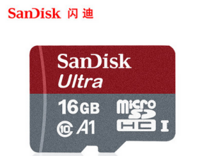
TF card reader, used to burn the image into the TF card

Display with HDMI interface

Micro HDMI to HDMI cable, used to connect the development board to an HDMI monitor or TV for display
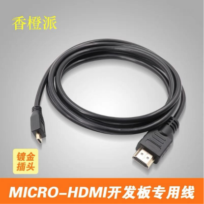
Note, if you want to connect a 4K monitor, make sure the HDMI cable supports 4K video output.
Power adapter. Orange Pi CM4 is recommended to use a 5V/3A Type-C power supply.
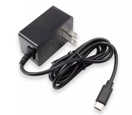
The mouse and keyboard of the USB interface, as long as the mouse and keyboard of the standard USB interface are acceptable, the mouse and keyboard can be used to control the Orange Pi development board

USB camera
PCIe NVMe SSD, the development board supports SSDs with M.2 2230 and M.2 2242 specifications. M.2 2280 is also supported, but it cannot be fixed with screws.
The development board does not come with an SPI Flash chip by default. You need to buy it yourself and then solder it on. The SPI Flash chip model we recommend is XM25QU128CWIQT08Q.
Please pay special attention to this point if you need to use SPIFlash+NVMe SSD to start the system.
100M or 1000M network cable, used to connect the development board to the Internet
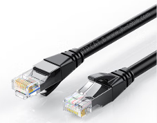
USB2.0 male-to-male data cable, used for burning images to eMMC, TF card, etc.
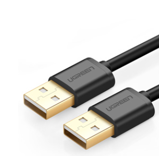
3.3V USB to TTL module and DuPont line, when using serial port debugging function, need USB to TTL module and DuPont line to connect the development board and computer
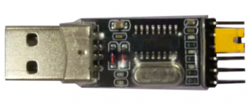
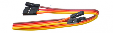
Personal computer with Ubuntu and Windows operating systems installed
1 Ubuntu22.04 PC Optional, used to compile Linux source code 2 Windows PC For burning Android and Linux images


The website for downloading the English version is:

The information mainly includes

Android source code: saved on Google Cloud Disk
b. Linux source code: saved on Github
c. User manual and schematic diagram: saved on Google Cloud Disk
d. Official tools: mainly include the software that needs to be used during the use of the development board
e. Android image: saved on Google Cloud Disk
f. Ubuntu image: saved on Google Cloud Disk
g. Debian image: saved on Google Cloud Disk
h. Orange Pi OS Arch image: saved on Google Cloud Disk
Method of burning Linux image to TF card based on Windows PC
|
Note that the Linux images mentioned here specifically refer to Linux distribution images such as Debian, Ubuntu and OPi OS Arch downloaded from the Orange Pi's data download page. |
How to use balenaEtcher to burn Linux image
- First prepare a TF card with a capacity of 16GB or larger. The transmission speed of the TF card must be class 10 or above. It is recommended to use TF cards from SanDisk and other brands.
- Then use the card reader to insert the TF card into the computer
- Download the Linux operating system image file compression package that you want to burn from the Orange Pi's data download page, and then use the decompression software to decompress it. Among the decompressed files, the file ending with ".img" is the image file of the operating system. The size is generally above 2GB.
- Then download the Linux image burning software-balenaEtcher, the download address is:
After entering the balenaEtcher download page, click the green download button to jump to the place where the software is downloaded
Then you can choose to download the Portable version of balenaEtcher software. The Portable version does not need to be installed, and you can use it by double-clicking to open it
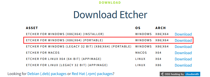
If you downloaded the version of balenaEtcher that needs to be installed, please install it first and then use it. If you downloaded the Portable version of balenaEtcher, just double-click to open it. The balenaEtcher interface after opening is as shown below:
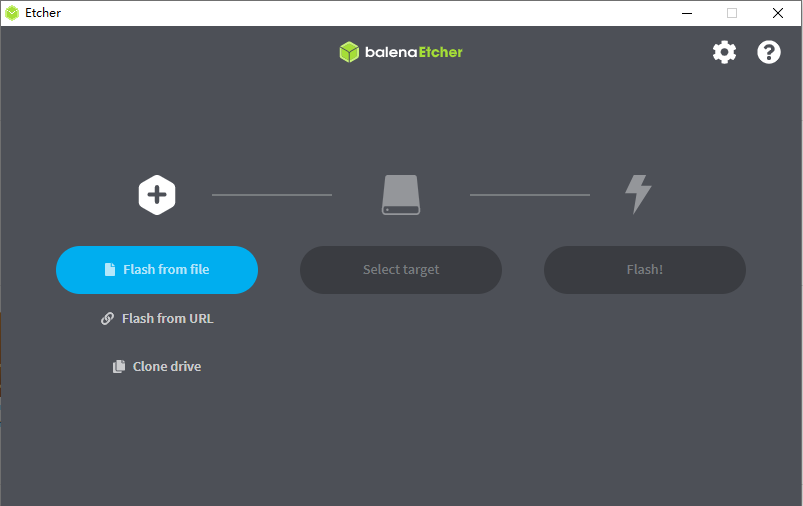
If the following error is prompted when opening balenaEtcher:
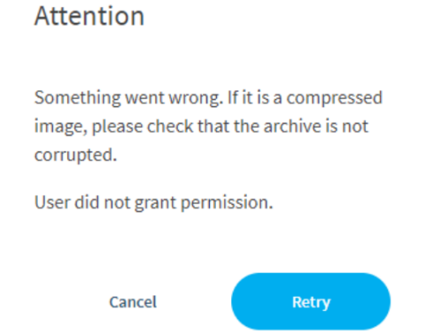
Please select balenaEtcher, right-click, and select Run as administrator.
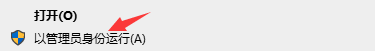


The specific steps to use balenaEtcher to burn a Linux image are as follows
a. First select the path of the Linux image file to be burned
b. Then select the drive letter of the TF card
c. Finally click Flash and it will start burning the Linux image to the TF card.
The interface displayed in the process of burning the Linux image by balenaEtcher is shown in the figure below, and the progress bar displays purple, indicating that the Linux image is being burned into the TF card
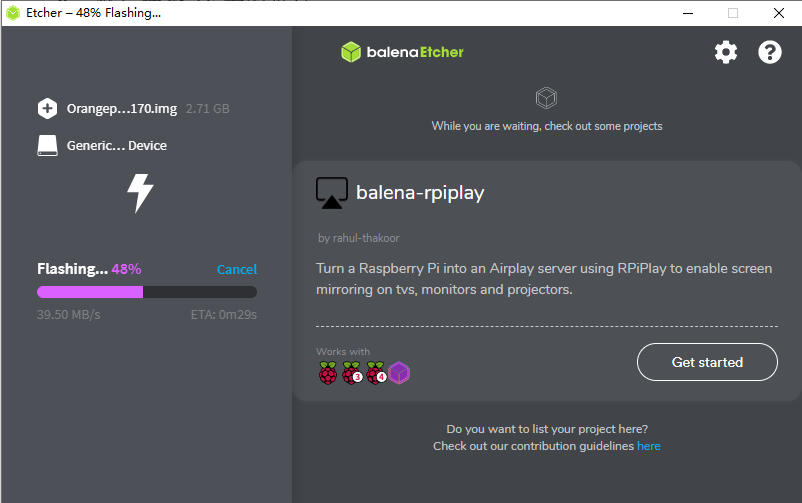
After burning the Linux image, balenaEtcher will also verify the image burned into the TF card by default to ensure that there is no problem in the burning process. As shown in the figure below, a green progress bar indicates that the image has been burnt, and balenaEtcher is verifying the burnt image
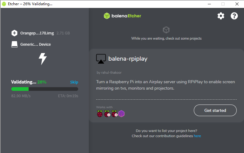
After successful burning, the display interface of balenaEtcher is as shown below. If the green indicator icon is displayed, it means that the image burning is successful. At this time, you can exit balenaEtcher, then pull out the TF card and insert it into the TF card slot of the development board for use.
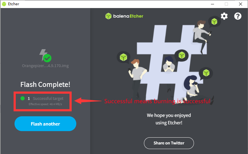


How to use RKDevTool to burn Linux image to TF card
First you need to prepare a good quality USB2.0 male-to-male data cable
You also need to prepare a TF card with a capacity of 16GB or larger. The transmission speed of the TF card must be class 10 or above. It is recommended to use TF cards from SanDisk and other brands.
Then download the Rockchip driver DriverAssitant_v5.12.zip and MiniLoader and the burning tool RKDevTool_Release_v3.15.zip from the Orange Pi information download page
On the Orange Pi information download page, first select the official tool, and then enter the folder below
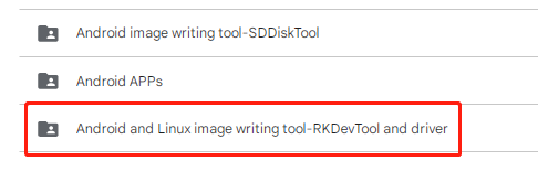
Then download all the files below
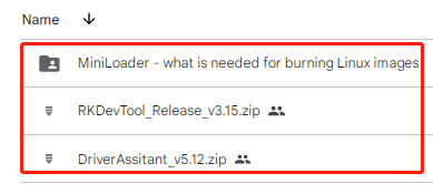
Note that the "MiniLoader-things needed to burn Linux images" folder will be referred to as the MiniLoader folder below.
Then download the compressed package of the Linux operating system image file you want to burn from the Orange Pi information download page, and then use the decompression software to decompress it. In the decompressed file, the file ending with ".img" is the image file of the operating system. , the size is generally above 2GB
Then use decompression software to decompress DriverAssitant_v5.12.zip, then find the DriverInstall.exe executable file in the decompressed folder and open it.
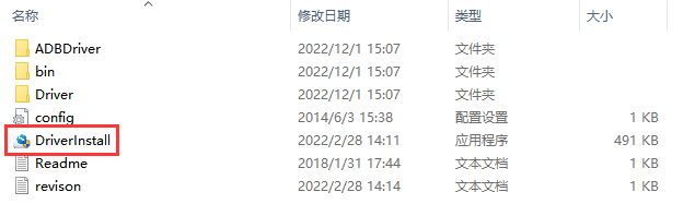
Open DriverInstall.exe and install the Rockchip microdriver as follows
Click the "Driver Installation" button
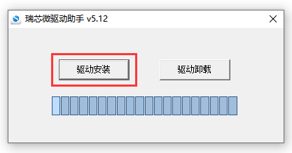
After waiting for a period of time, a window will pop up prompting "Driver installation successful", then click the "OK" button.
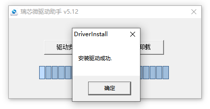
Then unzip RKDevTool_Release_v3.15.zip. This software does not need to be installed. Just find RKDevTool in the unzipped folder and open it.
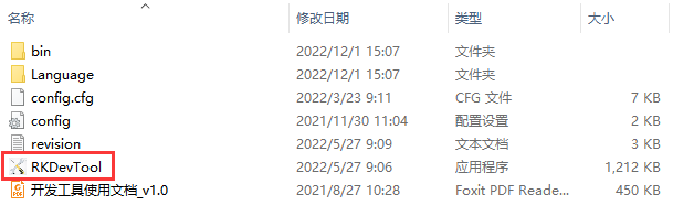
After opening the RKDevTool burning tool, because the computer has not connected to the development board through the USB2.0 male-to-male data cable at this time, the lower left corner will prompt "No device found"
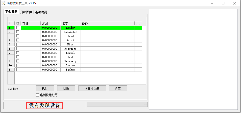
Then start burning the Linux image to the TF card
First, connect the development board to the Windows computer through a USB2.0 male-to-male data cable. The location of the USB2.0 programming port on the development board is as shown in the figure below.
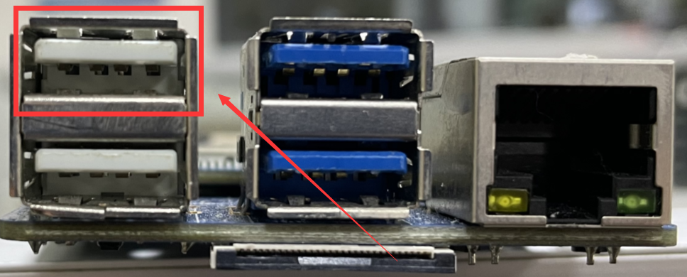
Make sure the TF card slot is not inserted into the TF card
Then press and hold the MaskROM button on the development board, the position of the MaskROM button on the development board is shown in the figure below:
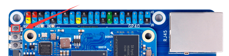
Then connect the development board to the power supply of the Type-C interface, power it on, and then release the MaskROM button.
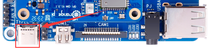
If the previous steps are successful, the development board will enter the MASKROM mode at this time, and the interface of the burning tool will prompt "found a MASKROM device"
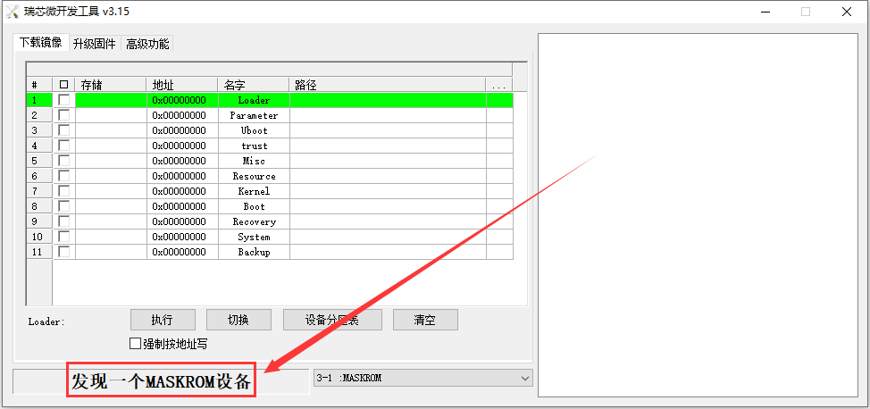
At this time, please insert the TF card into the TF card slot
Then place the mouse cursor in the area below
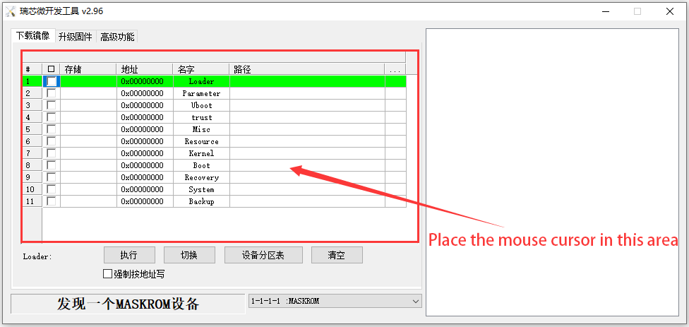
Then click the right mouse button and the selection interface shown in the figure below will pop up
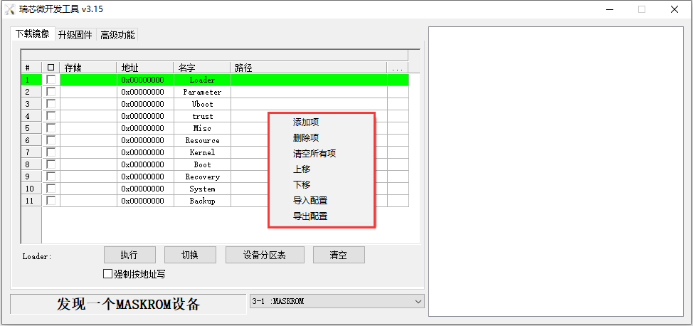
Then select the import configuration option
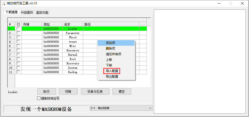
Then select the rk356x_linux_tfcard.cfg configuration file in the MiniLoader folder downloaded earlier, and click Open
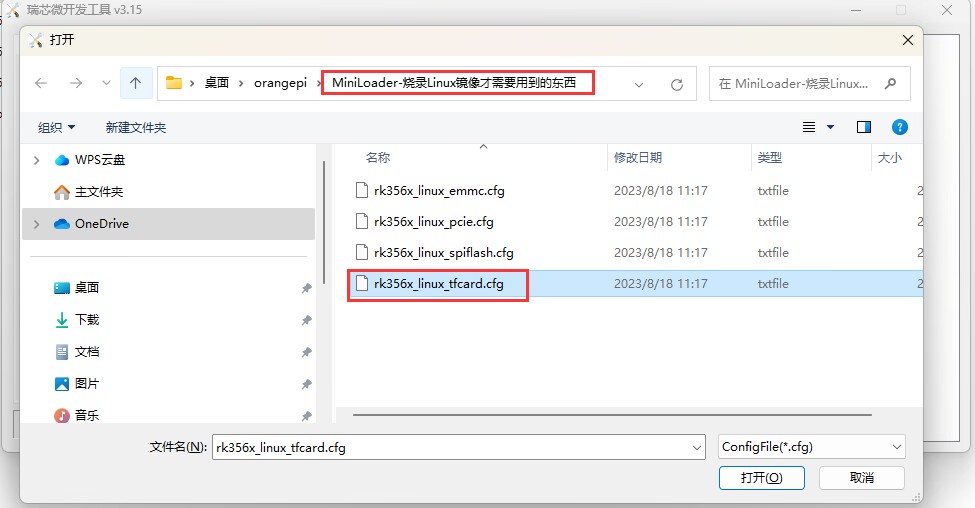
Then click OK
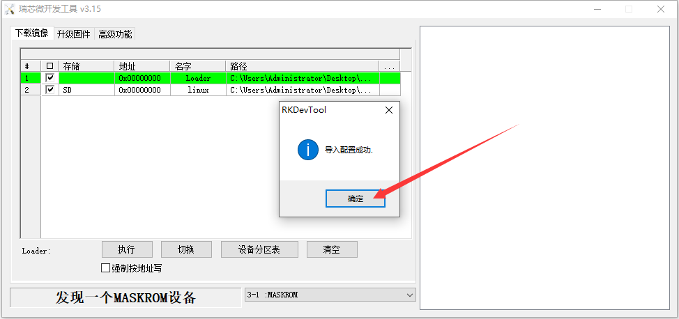
Then click the position shown in the figure below
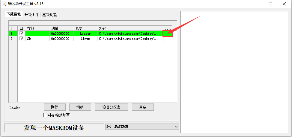
Then select MiniLoaderAll.bin in the MiniLoader folder downloaded earlier, and then click to open
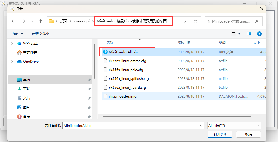
Then click on the location shown in the picture below
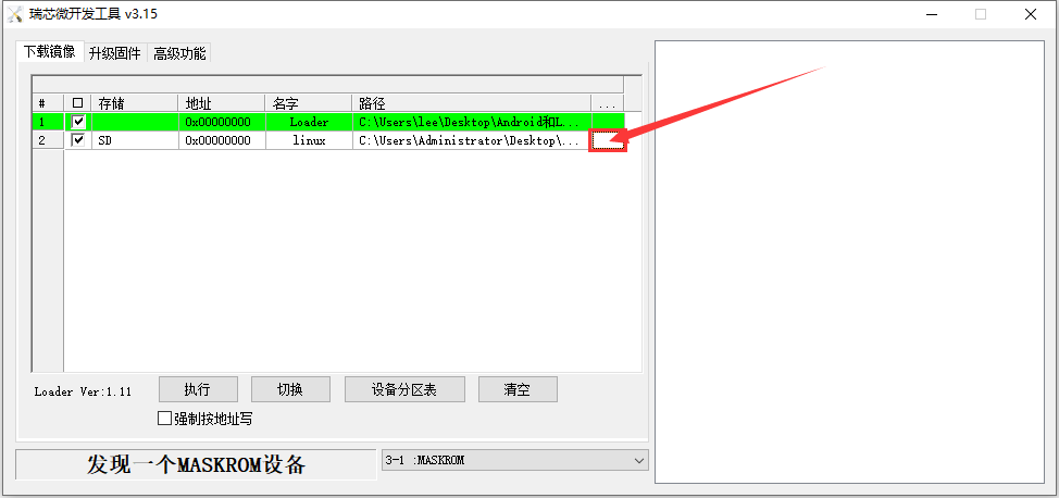
Then select the path of the Linux image you want to burn, and then click Open
Before burning the image, it is recommended to rename the Linux image to be burned to orangepi.img or another shorter name, so that you can see the percentage of the burning progress when burning the image.
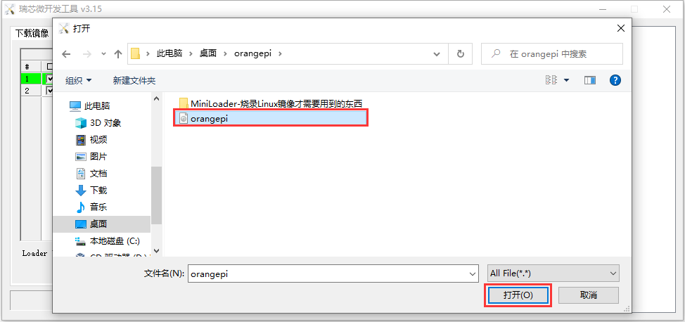
Then please check the option to force writing by address.
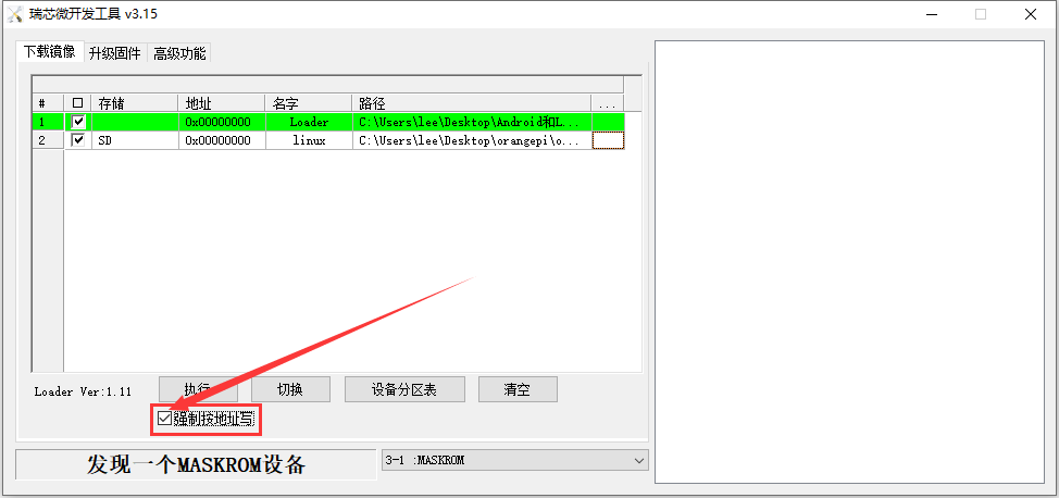
Click the execute button again and it will start burning the Linux image to the tf card of the development board.
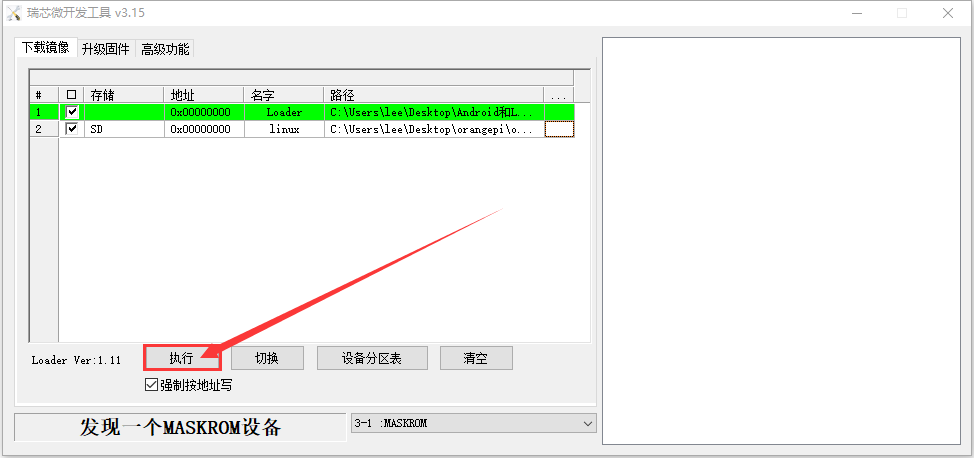
The display log after the r.Linux image is burned is as shown below
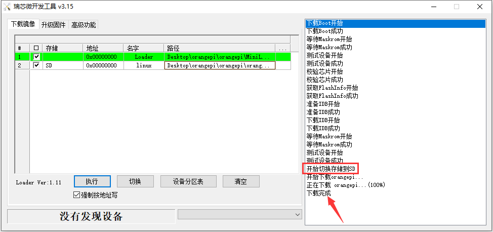
After burning the Linux image to the TF card, the Linux system will start automatically.


How to burn Linux image using Win32Diskimager
First prepare a TF card with a capacity of 16GB or larger. The transmission speed of the TF card must be class 10 or above. It is recommended to use TF cards from SanDisk and other brands.
Then use the card reader to insert the TF card into the computer
Then format the TF card
- SD Card Formatter can be used to format the TF card. The download address is:
https://www.sdcard.org/downloads/formatter/eula_windows/SDCardFormatterv5_WinEN.zip
After downloading, unzip and install directly, and then open the software
If only the TF card is inserted into the computer, the drive letter of the TF card will be displayed in the "Select card" column. If multiple USB storage devices are inserted into the computer, you can select the drive letter corresponding to the TF card through the drop-down box.
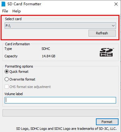
Then click "Format". A warning box will pop up before formatting. After selecting "Yes (Y)", formatting will begin.
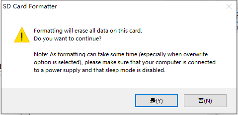
After formatting the TF card, the information shown in the figure below will pop up, click OK
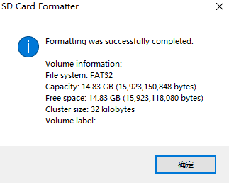


Download the compressed package of the Linux operating system image file you want to burn from the Orange Pi information download page, and then use the decompression software to decompress it. In the decompressed file, the file ending with ".img" is the image file of the operating system. The size is generally above 2GB
Use Win32Diskimager to burn the Linux image to the TF card
- The download page of Win32Diskimager is
http://sourceforge.net/projects/win32diskimager/files/Archive/
After downloading, you can install it directly. The Win32Diskimager interface is as follows
a) First select the path to the image file
b) Then confirm that the drive letter of the TF card is consistent with what is displayed in the "Device" column
c) Finally click "Write" to start burning
After the image writing is completed, click the "Exit" button to exit, and then you can pull out the TF card and insert it into the development board to start

Method of burning Linux image to TF card based on Ubuntu PC
|
Note that the Linux images here refer specifically to the images of Linux distributions like Debian, Ubuntu, and OPi OS Arch downloaded from the Orange Pi's data download page, and Ubuntu PC refers to a personal computer with Ubuntu installed. |
- First prepare a 16GB or larger capacity TF card, TF card transmission speed must be class10 or above, it is recommended to use Sandisk and other brands of TF card
- Then use the card reader to insert the TF card into the computer
- Download the balenaEtcher software, the download address is
After entering the balenaEtcher download page, click the green download button to jump to the place where the software is downloaded
Then choose to download the Linux version of the software
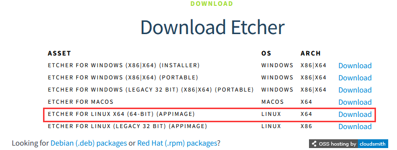
Download the compressed Linux operating system image file you want to burn from Orange Pi's data download page, and then use the decompression software to decompress it. Files ending with ".img "in the decompressed files are the image files of the operating system, and the size is generally more than 2GB
The following command is used to decompress the compressed package ending in 7z
test@test:~$ 7z x Orangepicm4_1.0.0_debian_bullseye_desktop_xfce_linux5.10.160.7z
test@test:~$ ls Orangepicm4_1.0.0_debian_bullseye_desktop_xfce_linux5.10.160.*
Orangepicm4_1.0.0_debian_bullseye_desktop_xfce_linux5.10.160.7z Orangepicm4_1.0.0_debian_bullseye_desktop_xfce_linux5.10.160.sha #Checksum file
Orangepicm4_1.0.0_debian_bullseye_desktop_xfce_linux5.10.160.img #Image file
After decompressing the image, you can first use the sha256sum -c *.sha command to calculate whether the checksum is correct, if the success indicates that the downloaded image is not wrong, you can rest assured to burn to the TF card, if the checksum does not match that there is a problem with the downloaded image, please try to re-download
test@test:~$ sha256sum -c *.sha
Orangepicm4_1.0.0_debian_bullseye_desktop_xfce_linux5.10.160.img: OK
Then double-click balenaEtcher-1.5.109-x64.AppImage in the graphical interface of Ubuntu PC to open balenaEtcher (no installation required), and the interface after balenaEtcher is opened is shown as the following figure
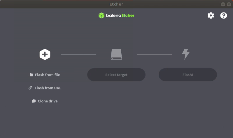
The specific steps to burn a Linux image using balenaEtcher are shown below
a. Select the path of the Linux image file to be burned
b. Then select the drive letter of the TF card
c. Finally, clicking Flash will start burning the Linux image to the TF card
The interface displayed during balenaEtcher burning the Linux image is as shown in the following figure. In addition, the progress bar showing purple indicates that the Linux image is burning to the TF card
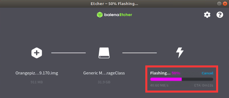
After the Linux image is burned, balenaEtcher will also verify the image burned to the TF card by default to ensure that there is no problem in the burning process. As shown in the following figure, the green progress bar indicates that the image has been burned, and balenaEtcher is verifying the burned image
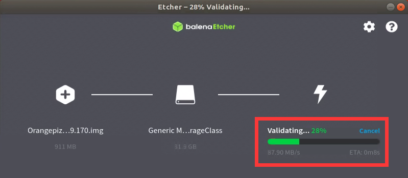


The display interface of balenaEtcher after the successful burning is shown as the following figure. If the green indicator icon is displayed indicating that the image is burned successfully, you can exit balenaEtcher at this time, and then pull out the TF card and insert it into the TF card slot of the development board
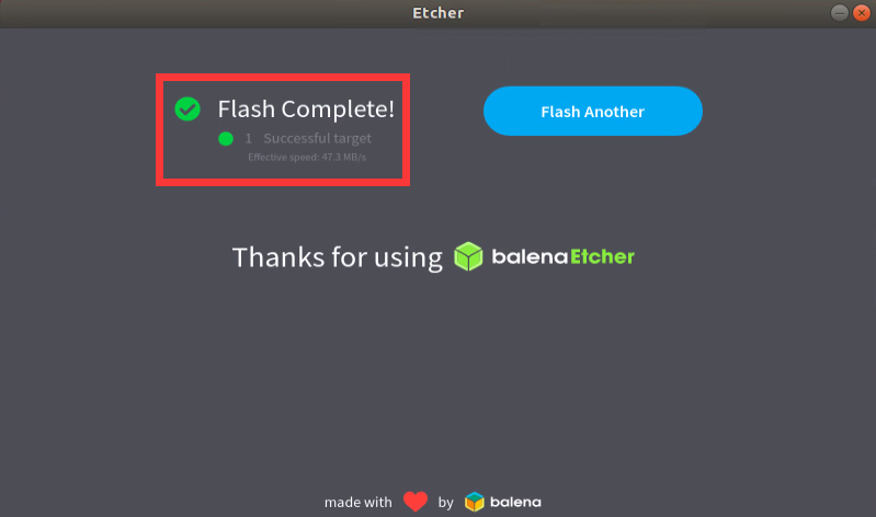

Methods for burning Linux images to eMMC
Methods for burning Linux images to eMMC using RKDevTool
|
Note that all of the following actions are performed on a Windows computer. |
|
Note that the Linux images here specifically refer to the images of Linux distributions such as Debian, Ubuntu, and OPi OS Arch downloaded from the Orange Pi's data download page. |
First of all, you need to prepare a good quality USB2.0 public-to-public data cable
Then download the Rockchip DriverAssitant_v5.12.zip and MiniLoader and the burning tool RKDevTool_Release_v3.15.zip from Orange Pi's data download page
On the Orange Pi's data download page, first select the official tool and then go to the following folder
Then download all the files below
Note that the folder "MiniLoader- What you Need to burn Linux images" is hereinafter referred to as the MiniLoader folder.
Download the compressed Linux operating system image file you want to burn from the Orange Pi's data download page, and then use the decompression software to decompress it. After decompressing the file, the file ending with ".img "is the image file of the operating system, and the size is generally more than 2GB
Then use the decompression software to decompress DriverAssitant_v5.12.zip, and then find the DriverInstall.exe executable file in the decompressed folder and open it
Open DriverInstall.exe and install the SWick micro driver as follows
Click the "Driver Installation" button
Wait for a period of time, the pop-up window will prompt > "Driver installation successful", and then click the > "OK" button
Then decompress RKDevTool_Release_v3.15.zip, this software does not need to be installed, find RKDevTool in the decompressed folder and open it
After opening the RKDevTool burning tool, because the computer has not connected to the development board through the USB2.0 public-to-public data cable at this time, the lower left corner will indicate "no device found".
Then start burning the Linux image into eMMC
First, connect the development board to the Windows computer through the USB2.0 male-to-public data cable. The position of the USB2.0 burning port on the development board is shown in the figure below
Ensure that no TF card is inserted into the development board and no power supply is connected
Then press and hold the MaskROM button on the development board. The position of the MaskROM button on the development board is shown as follows:
Then connect the Type-C interface to the development board, and power on, and then you can release the MaskROM button
If the previous steps are smooth, the development board will enter MASKROM mode at this time, and the interface of the burning tool will prompt "Found a MASKROM device".
Then place the mouse cursor on the field below
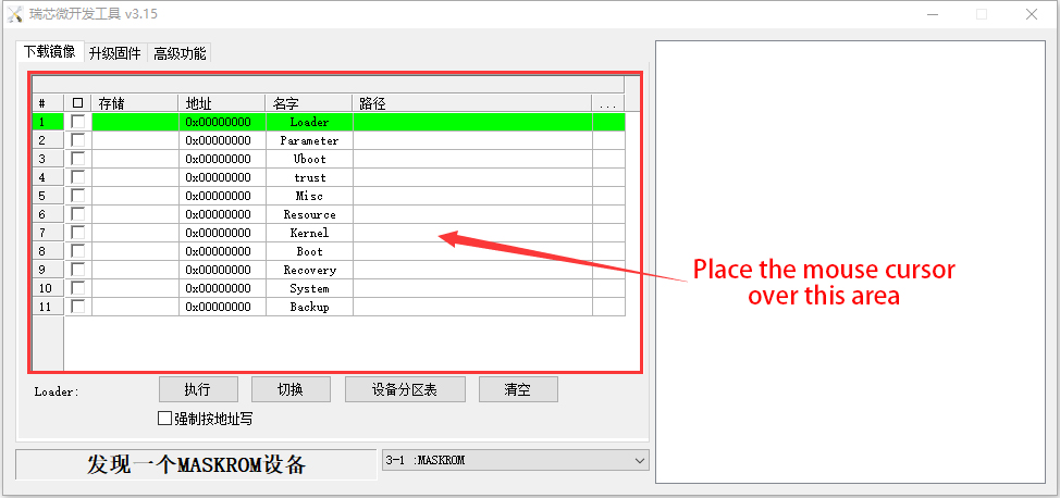
Then click the right mouse button to pop up the selection interface as shown in the following figure
Then select the Import configuration option
Then select the rk356x_linux_emmc.cfg configuration file in the MiniLoader folder downloaded earlier and click Open
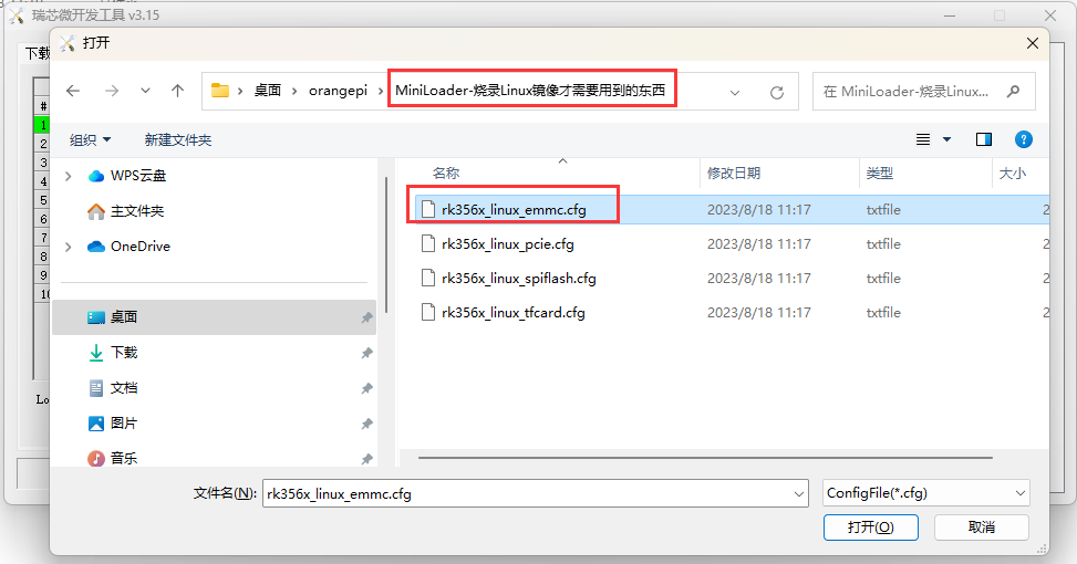
Then click OK
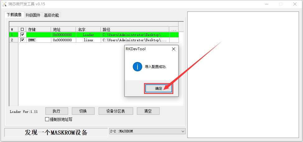
Then click on the location shown in the image below
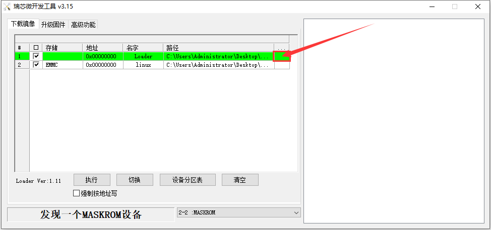
Select MiniLoaderAll.bin from the MiniLoader folder downloaded earlier, and then click Open
Then click on the location shown in the image below
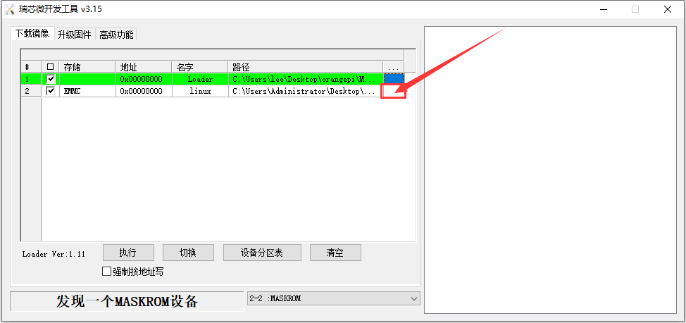
Then select the path of the Linux image you want to burn and click Open
Before burning the image, it is recommended to rename the Linux image to orangepi.img or something shorter so that you can see the percentage of the burn progress when burning the image.
Then check the Force write to address option
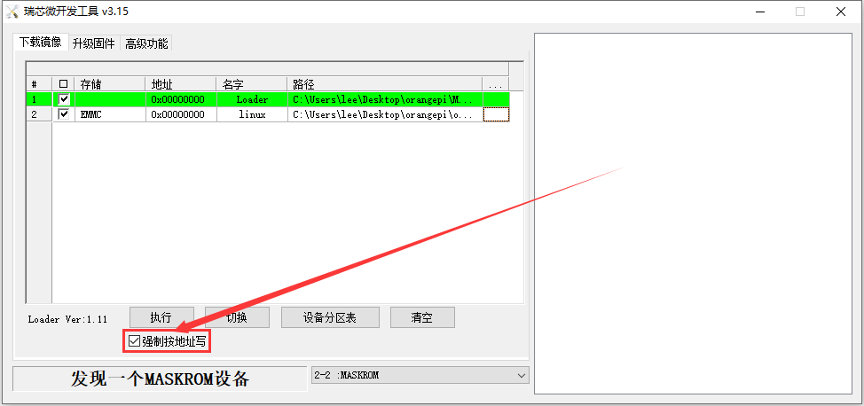
Click the Execute button again to start burning the Linux image to eMMC on the development board

The following figure shows the display log after the Linux image is burned
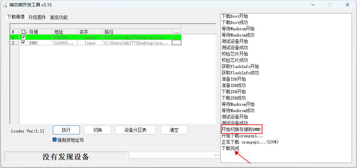
After the Linux image is burned into eMMC, the Linux system automatically starts


How to burn a Linux image to eMMC using the dd command
|
Note that by Linux images, I specifically mean images of Linux distributions such as Debian, Ubuntu, or OPi OS Arch downloaded from the Orange Pi's data download page. |
Using dd command to burn Linux image to eMMC needs TF card to complete, so first need to burn Linux image to TF card, and then use TF card to start the development board into the Linux system. For the method of burning a Linux image to a TF card, see the two sections for the method of burning a Linux image to a TF Card based on a Windows PC and the method of burning a Linux image to a TF card based on an Ubuntu PC.
After starting the Linux system with the TF card, we first upload the decompressed Linux image file (Debian, Ubuntu image or OPi OS (Arch) image downloaded from the official website) to the TF card. For details about how to upload a Linux image file to the development board, see section Uploading Files to the Linux system on the Development Board.
After uploading the image to the Linux system of the development board, we can enter the storage path of the image file in the command line of the Linux system of the development board. For example, I saved the Linux image of the development board in the directory /home/orangepi/Desktop. Then go to the /home/orangepi/Desktop directory and you will see the uploaded image file.
orangepi@orangepi:~$ cd /home/orangepi/Desktop
orangepi@orangepi:~/Desktop$ ls
Orangepicm4_x.x.x_debian_bullseye_desktop_xfce_linux5.10.160.img
How to enter the development board Linux system command line?
1. For details about how to log in to the terminal through the serial port, see section Debugging Serial Port.
2. For details about how to remotely log in to the Linux operating system over ssh, see section "Logging In to the Development Board over SSH".
3. If you are connected to a display screen such as HDMI or LCD, you can open a command line terminal on the desktop.
Next, we first use the following command to identify the eMMC device node
orangepi@orangepi:~/Desktop$ ls /dev/mmcblk*boot0 | cut -c1-12
/dev/mmcblk0
Then we can use the dd command to clear eMMC, pay attention to the of= parameter after please fill in the output result of the above command
orangepi@orangepi:~/Desktop$ sudo dd bs=1M if=/dev/zero of=/dev/mmcblk0 count=1000 status=progress
orangepi@orangepi:~/Desktop$ sudo sync
You can then use the dd command to burn the Linux image of the development board into eMMC
if = parameter in the command is to fill in behind the Linux + Linux mirror mirror to store the full path name (such as/home/orangepi/Desktop/Linux image name). Since we have entered the path of the Linux image above, we only need to fill in the name of the Linux image.
Do not copy the Linux image name in the following command. Replace it with the actual image name (because the version of the image may be updated).
sudo dd bs=1M if=Orangepicm4_x.x.x_debian_bullseye_desktop_xfce_linux5.10.160.img of=/dev/mmcblk0 status=progress
sudo sync
Note that if you are uploading a.7z or.xz Linux image file, please decompress it before using the dd command to burn it.
A detailed description of all the parameters of the dd command and more usage can be seen by running the man dd command on Linux.
After successfully burning the Linux image of the development board to eMMC, you can use the poweroff command to shut down. Then pull out the TF card, power it on again, and the Linux system in eMMC will be started.
Method of burning Linux image to SPIFlash+NVMe SSD
|
Before starting to burn the image, it is necessary to ensure that the SPI Flash chip has been affixed to the development board, because the development board does not have SPI Flash chip when it is shipped, so it is necessary to purchase and weld it by itself. We suggest that the SPI Flash chip model be XM25QU128CWIQT08Q |
|
eMMC has a higher boot priority than NVMe SSDS. Therefore, you need to clear the eMMC system before burning the image. For details about how to clear eMMC, see section "Clearing eMMC using RKDevTool" |
|
Note that the Linux images here specifically refer to the images of Linux distributions such as Debian, Ubuntu, and OPi OS Arch downloaded from the Orange Pi's data download page. |
|
Note that all of the following actions are performed on a Windows computer. |
Method of burning using RKDevTool
First of all, you need to prepare an NVMe SSD. The PCIe supported by the M.2 slot on the development board is PCIe2.0x1, and the theoretical maximum speed is 500MB/s. Pci 3.0 and PCI 4.0 NVMe SSDS are also available, but the speed is only up to the speed of PCI 2.0x1.
M.2 2230 SSD specifications are as follows
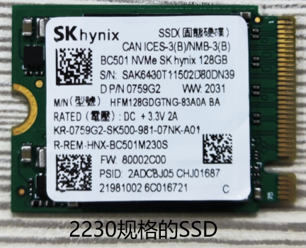
M.2 2242 SSDS are described as follows
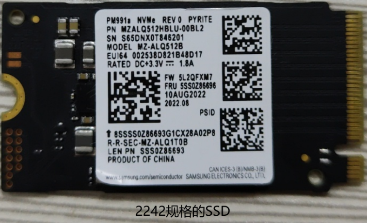
Insert the NVMe SSD into the M.2 PCIe port on the development board and secure it
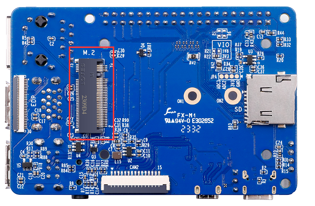
Please ensure that the SPI Flash is affixed to the development board. The position of SPI Flash on the development board is shown in the figure below. No other Settings are required before burning
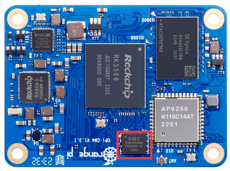
Then you need to prepare a good quality USB2.0 public-to-public data cable
Then download the Rockchip DriverAssitant_v5.12.zip and MiniLoader and the burning tool RKDevTool_Release_v3.15.zip from Orange Pi's data download page
On the Orange Pi's data download page, first select the official tool and then go to the following folder
Then download all the files below
Note that the folder "MiniLoader- What you Need to burn Linux images" is hereinafter referred to as the MiniLoader folder.
Download the compressed Linux operating system image file you want to burn from the Orange Pi's data download page, and then use the decompression software to decompress it. In the decompressed file, the file ending with ".img "is the image file of the operating system, and the size is generally more than 2GB
Then use the decompression software to decompress DriverAssitant_v5.12.zip, and then find the DriverInstall.exe executable file in the decompressed folder and open it
Open DriverInstall.exe and install the Rockchip driver as follows
Click the "Driver Installation" button
Wait for a period of time, the pop-up window will prompt "Driver installation successful", and then click the "OK" button
Then decompress RKDevTool_Release_v3.15.zip, this software does not need to be installed, find RKDevTool in the decompressed folder and open it
After opening the RKDevTool burning tool, because the computer has not connected to the development board through the USB2.0 public-to-public data cable at this time, the lower left corner will indicate "No device found".
Then start burning the Linux image to the SSD
First, connect the development board to the Windows computer through the USB2.0 male-to-public data cable. The position of the USB2.0 burning interface on the development board is shown in the figure below
Ensure that no TF card is inserted into the development board and no power supply is connected
Then press and hold the MaskROM button on the development board. The position of the MaskROM button on the development board is shown as follows:
Then connect the Type-C interface to the development board, and power on, and then you can release the MaskROM button
If the previous steps are smooth, the development board will enter MASKROM mode at this time, and the interface of the burning tool will prompt "Found a MASKROM device".
Then place the mouse cursor on the field below
Then click the right mouse button to pop up the selection interface as shown in the following figure
Then select the Import configuration option
Then go to the previously downloaded MiniLoader folder, select the rk356x_linux_pcie.cfg configuration file, and click Open
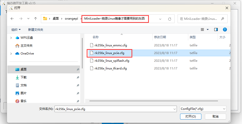
Then click OK
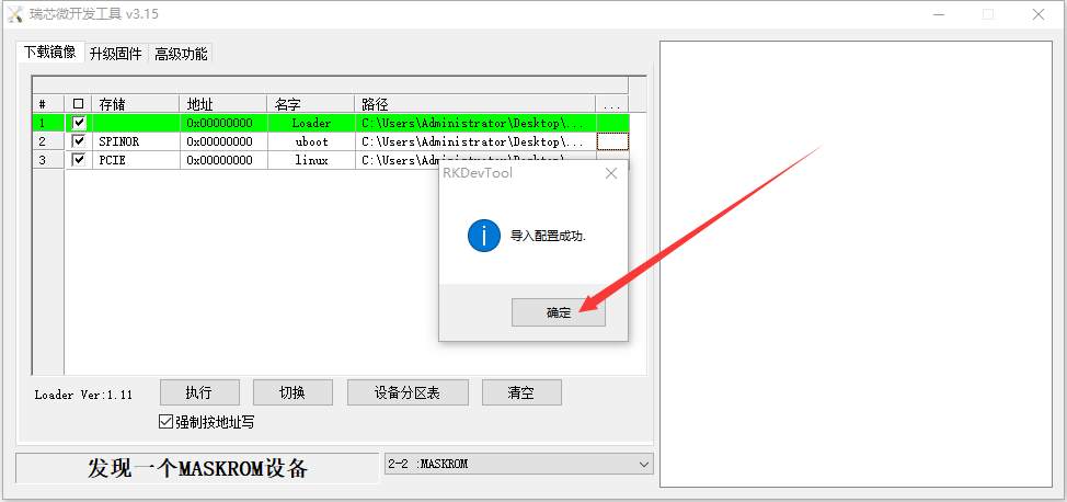
Then click on the location shown in the image below
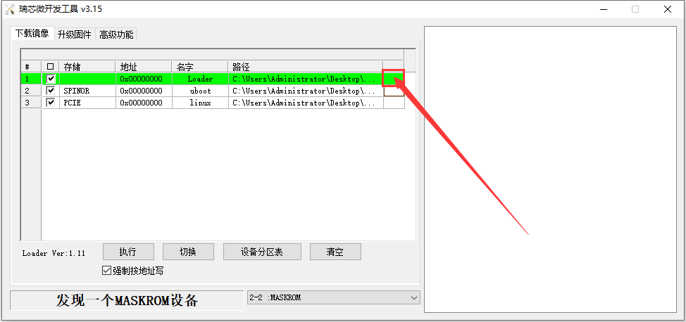
Select MiniLoaderAll.bin from the MiniLoader folder downloaded earlier, and then click Open
Then click on the location shown in the image below
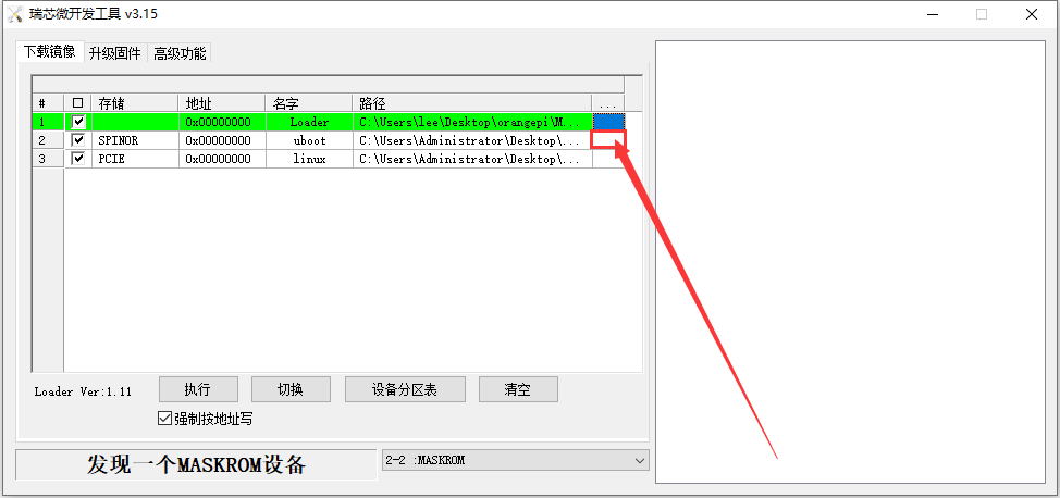
Then go to the previously downloaded MiniLoader folder, select rkspi_loader.img, and click Open
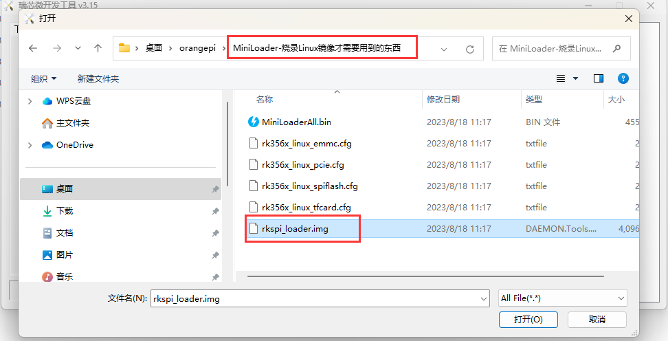
Then click on the location shown in the image below
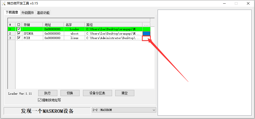
Then select the path of the Linux image you want to burn and click Open
Before burning the image, it is recommended to rename the Linux image to orangepi.img or something shorter so that you can see the percentage of the burn progress when burning the image.
Then select Force Write to address
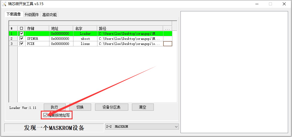
Click the Run button again to start burning the Linux image to the SSD
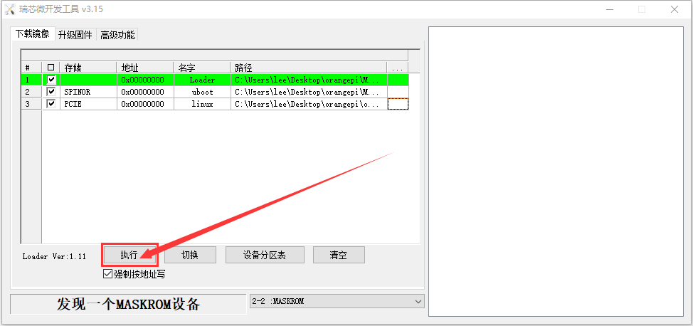
The display log of the S.lux image after burning is shown in the following figure
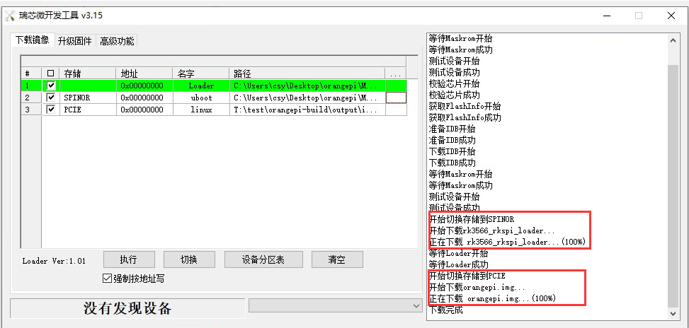
If you have problems with burning, please clear the SPIFlash first and then burn the test. For instructions on how to clear SPIFlash, refer to the section on how to clear SPIFlash using RKDevTool.
After the image is burned, the Linux system in the SPIFlash+PCIe SSD automatically starts. If it does not start properly, power it on again.


Method of burning using dd command
First of all, you need to prepare an NVMe SSD. The PCIe supported by the M.2 slot on the development board is PCIe2.0x1, and the theoretical maximum speed is 500MB/s. Pci 3.0 and PCI 4.0 NVMe SSDS are also available, but the speed is only up to the speed of PCI 2.0x1.
M.2 2230 SSDS are as follows
M.2 2242 SSDS are described as follows
Insert the NVMe SSD into the M.2 PCIe port on the development board and secure it
Please ensure that the SPI Flash is affixed to the development board. The position of SPI Flash on the development board is shown in the figure below. No other Settings are required before burning
Burning Linux image to SPIFlash+NVMe SSD requires TF card to complete, so first need to burn Linux image to TF card, and then use the TF card to start the development board into the Linux system. For the method of burning a Linux image to a TF card, see the two sections on the method of burning a Linux image to a TF card based on a Windows PC and the method of burning a Linux image to a TF card based on an Ubuntu PC.
After starting the Linux system with TF card, we first burn the u-boot image into SPI Flash
Run nand-sata-installl first. Ordinary users remember to add sudo permission
orangepi@orangepi:~$ sudo nand-sata-install
Then select 7 Install/Update ther bootloader on SPI Flash
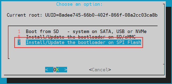
- Then select <Yes>
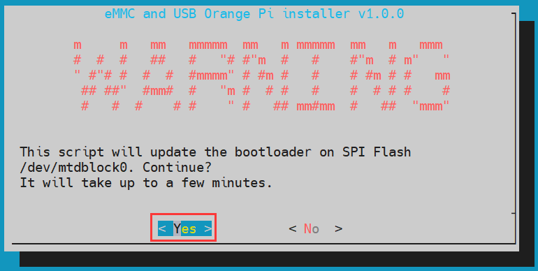
- Then please wait patiently for the burning to complete, after the burning is completed, it will be displayed as follows (a Done will be displayed in the lower left corner) :
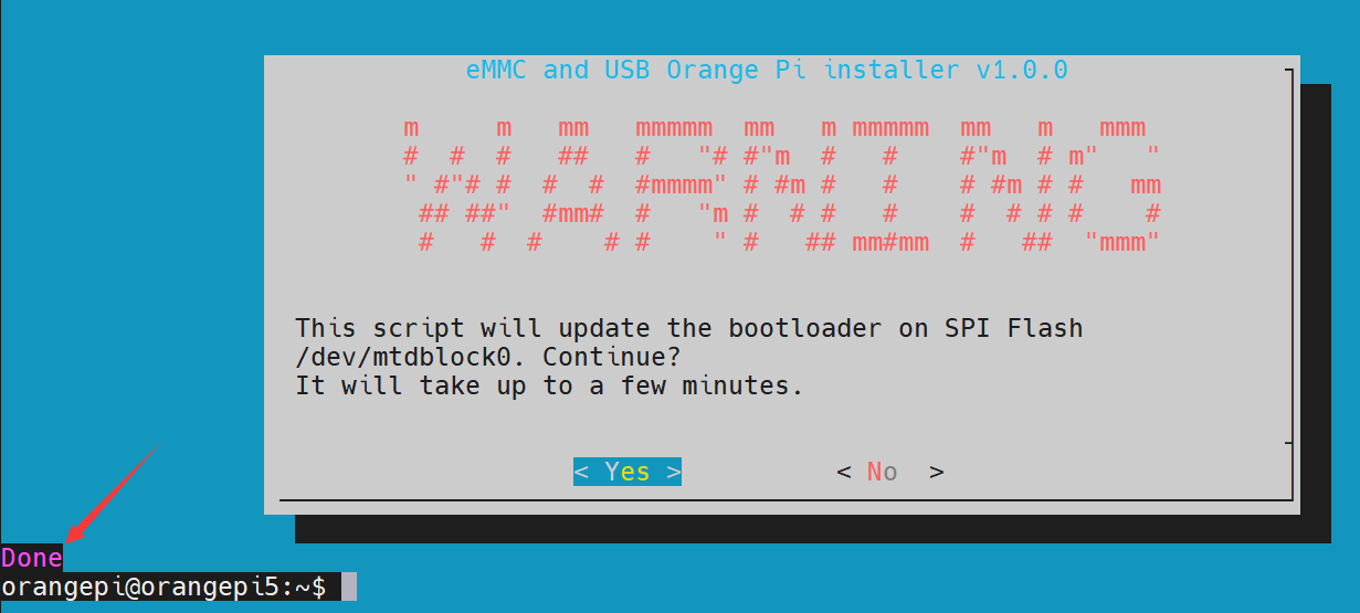


Then upload the Linux image file (Debian or Ubuntu image downloaded from the official website) to the TF card. For details about how to upload a Linux image file to the development board, see section Uploading Files to the Linux system on the Development Board.
After uploading the image to the Linux system of the development board, we can enter the storage path of the image file in the command line of the Linux system of the development board. For example, I saved the Linux image of the development board in the directory /home/orangepi/Desktop. Then go to the /home/orangepi/Desktop directory and you will see the uploaded image file.
orangepi@orangepi:~$ cd /home/orangepi/Desktop
orangepi@orangepi:~/Desktop$ ls
Orangepi3b_x.x.x_debian_bullseye_desktop_xfce_linux5.10.160.img
How to enter the development board Linux system command line?
1. For details about how to log in to the terminal through the serial port, see section Debugging Serial Port.
2. For details about how to remotely log in to the Linux operating system over ssh, see section "Logging In to the Development Board over SSH".
3. If you are connected to a display screen such as HDMI or LCD, you can open a command line terminal on the desktop.
Next, let's first make sure that NVMe SSD has been properly recognized by Linux development board. If the NVMe SSD is correctly identified, run the sudo fdisk -l command to view information about the nvme
orangepi@orangepi:~/Desktop$ sudo fdisk -l | grep "nvme0n1"
Disk /dev/nvme0n1: 1.86 TiB, 2048408248320 bytes, 4000797360 sectors
Use the lspci command to see an NVME-related PCI device
orangepi@orangepi:~/Desktop$ lspci
00:00.0 PCI bridge: Fuzhou Rockchip Electronics Co., Ltd Device 3566 (rev 01)
01:00.0 Non-Volatile memory controller: Realtek Semiconductor Co., Ltd. Device 5765 (rev 01)
Then we can use the dd command to empty the NVMe SSD (optional)
orangepi@orangepi3b:~/Desktop$ sudo dd bs=1M if=/dev/zero of=/dev/nvme0n1 count=2000 status=progress
orangepi@orangepi3b:~/Desktop$ sudo sync
You can then use the dd command to burn the Linux image of the development board into the NVMe SSD
if = parameter in the command is to fill in behind the Linux + Linux mirror image to store the full path name (such as/home/orangepi/Desktop/Linux image name). Since we have entered the path of the Linux image above, we only need to fill in the name of the Linux image.
Do not copy the Linux image name in the following command. Replace it with the actual image name (because the version of the image may be updated).
sudo dd bs=1M if=Orangepi3b_x.x.x_debian_bullseye_desktop_xfce_linux5.10.160.img of=/dev/nvme0n1 status=progress
sudo sync
Note that if you are uploading a.7z or.xz or.gz Linux image file, remember to decompress it before burning it with the dd command.
A detailed description of all the parameters of the dd command and more usage can be seen by running the man dd command on Linux.
After successfully burning the Linux image of the development board to the NVMe SSD, you can use the poweroff command to shut down. Then, pull out the TF card, press the power button again, and then start the Linux system in the SPIFlash+NVMe SSD.
After starting the system in the NVMe SSD, run the df -h command to view the actual hard disk capacity
128GB NVMe SSD
orangepi@orangepi:~$ df -h
Filesystem Size Used AvailUse% Mounted on
udev3.8G 8.0K 3.8G 1% /dev
tmpfs 769M 1.4M 768M 1% /run
/dev/nvme0n1p2118G 5.8G 111G 5% /
tmpfs 3.8G 03.8G 0% /dev/shm
tmpfs 5.0M 4.0K 5.0M 1% /run/lock
tmpfs 3.8G 16K 3.8G 1% /tmp
/dev/nvme0n1p1256M 90M 166M 36% /boot
/dev/zram1194M 9.9M 170M 6% /var/log
tmpfs 769M 60K 769M 1% /run/user/1000
tmpfs 769M 48K 769M 1% /run/user/0
2TB NVMe SSD
orangepi@orangepi:~$ df -h
Filesystem Size Used AvailUse% Mounted on
udev3.8G 8.0K 3.8G 1% /dev
tmpfs 769M 1.4M 768M 1% /run
/dev/nvme0n1p21.9T 4.1G 1.8T 1% /
tmpfs 3.8G 03.8G 0% /dev/shm
tmpfs 5.0M 4.0K 5.0M 1% /run/lock
/dev/zram23.7G 76K 3.5G 1% /tmp
/dev/nvme0n1p1256M 90M 166M 36% /boot
/dev/zram1194M 9.9M 170M 6% /var/log
tmpfs 769M 60K 769M 1% /run/user/1000
tmpfs 769M 48K 769M 1% /run/user/0
When the TF card and NVMe SSD burn exactly the same system, if the TF card and NVMe SSD are inserted in the development board, power on the development board at this time, u-boot will give priority to start the system in the TF card. However, since the TF card and the NVMe SSD system are identical, the UUID of the /boot partition and rootfs partition in the two storage devices are the same, which will cause the TF card may load the NVMe SSD partition when it is started. Run the following script to solve this problem.
orangepi@orangepi:~$ sudo fix_mmc_ssd.sh
An identical system means that the mirror name is exactly the same. Even if it is a Debian11 system, the version is different.
Method of burning using balenaEtcher software
First of all, you need to prepare an NVMe SSD. The PCIe supported by the M.2 slot on the development board is PCIe2.0x1, and the theoretical maximum speed is 500MB/s. Pci 3.0 and PCI 4.0 NVMe SSDS are also available, but the speed is only up to the speed of PCI 2.0x1.
M.2 2230 SSDS are as follows
M.2 2242 SSDS are described as follows
Insert the NVMe SSD into the M.2 PCIe port on the development board and secure it
Please ensure that the SPI Flash is affixed to the development board. The position of SPI Flash on the development board is shown in the figure below. No other Settings are required before burning
Burning Linux image to SPIFlash+NVMe SSD requires TF card to complete, so first need to burn Linux image to TF card, and then use the TF card to start the development board into the Linux system. For the method of burning a Linux image to a TF card, see the two sections on the method of burning a Linux image to a TF card based on a Windows PC and the method of burning a Linux image to a TF card based on an Ubuntu PC.
After starting the Linux system in the TF card, please make sure that the NVMe SSD has been properly recognized by Linux on the development board. If the NVMe SSD is correctly identified, run the sudo fdisk -l command to view information about the nvme
orangepi@orangepi:~/Desktop$ sudo fdisk -l | grep "nvme0n1"
Disk /dev/nvme0n1: 1.86 TiB, 2048408248320 bytes, 4000797360 sectors
Use the lspci command to see an NVME-related PCI device
orangepi@orangepi:~/Desktop$ lspci
00:00.0 PCI bridge: Fuzhou Rockchip Electronics Co., Ltd Device 3566 (rev 01)
01:00.0 Non-Volatile memory controller: Realtek Semiconductor Co., Ltd. Device 5765 (rev 01)
balenaEtcher has been pre-installed in the Linux image, and the opening method is as follows:

If the balenaEtcher arm64 version is not pre-installed, for details about how to download and install the balenaEtcher arm64 version, see section How to Download and Install the balenaEtcher arm64 version.

- The interface after balenaEtcher is opened is as follows:

The method of using balenaEtcher to burn u-boot to SPI Flash on the development board is as follows:
- First click Flash from file
- Go to /usr/lib/linux-u-boot-legacy-orangepi3b_1.x.x_arm64, select rkspi_loader.img, and click Open
Open rkspi_loader.img. The following interface is displayed:
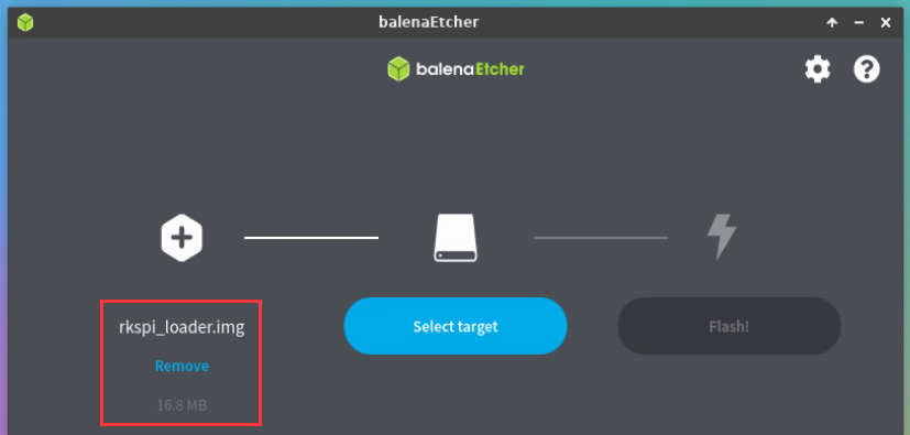
Then click Select target
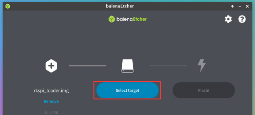
- Then click Show 2 hidden to open the option for more storage devices
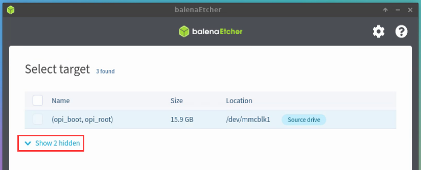
- Then Select the SPI Flash device name /dev/mtdblock0 and click Select
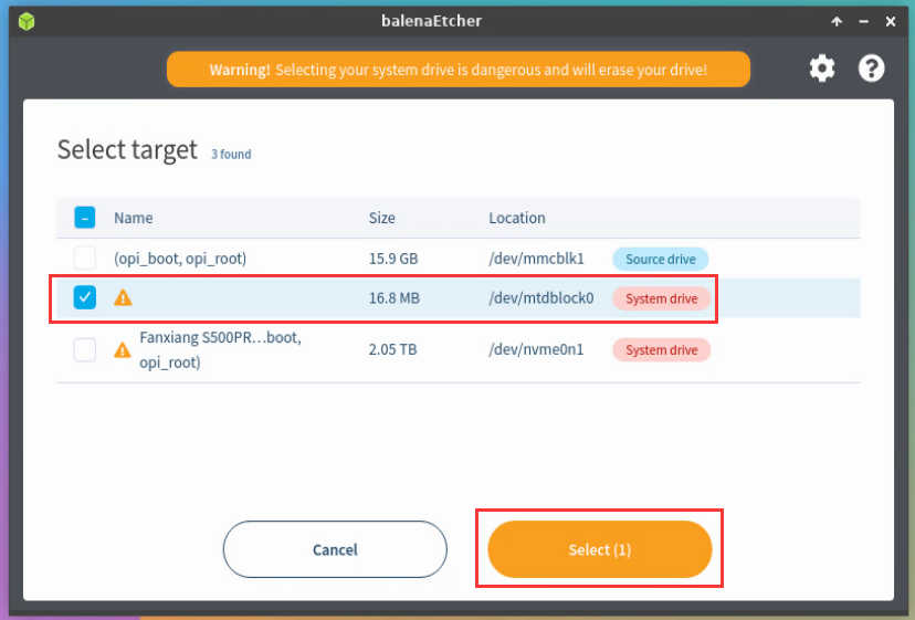
- Then click Flash
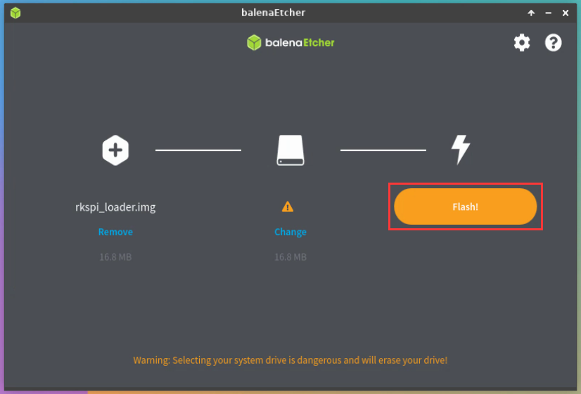
- Then click Yes, I’m sure
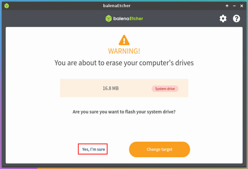
- Then enter the password orangepi of the development board Linux system, and the u-boot image will be burned to the SPI Flash
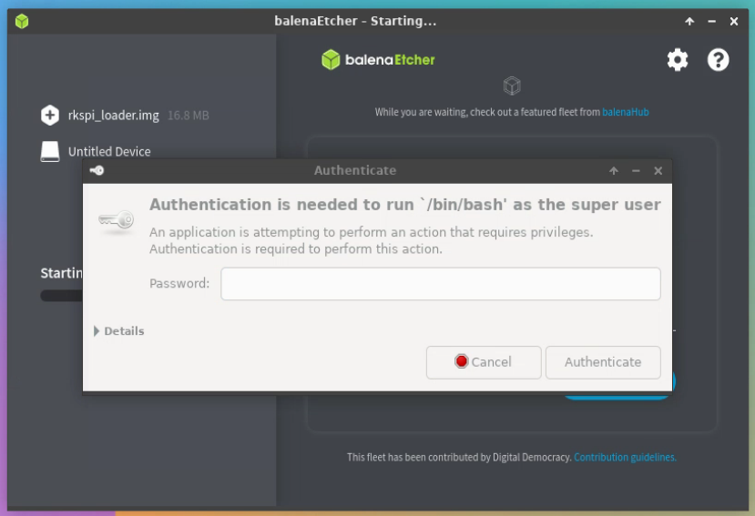
- The burning process is displayed as follows:
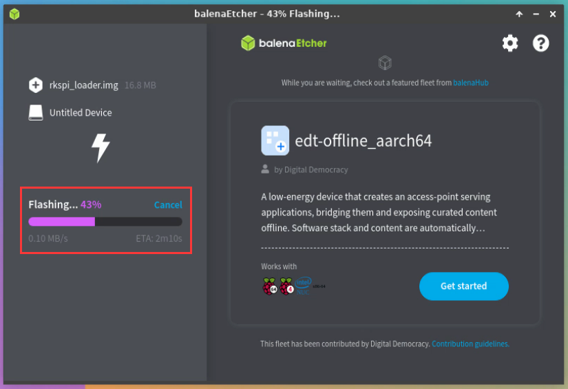
- The display after burning is as follows:
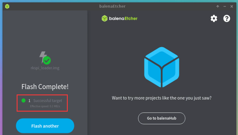


Method of burning the Linux system in the TF card to the NVMe SSD (this method is equivalent to cloning the system in the TF card to the NVMe SSD)
- First click Clone drive
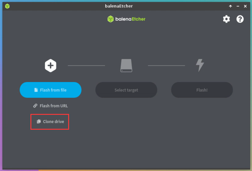
- Then select the device name of the TF card /dev/mmcblk1
- The interface after opening the TF card is as follows:
- Then click Select target
- Then click Show 2 hidden to open the option for more storage devices
- Then Select the device name for the NVMe SSD /dev/nvme0n1 and click Select
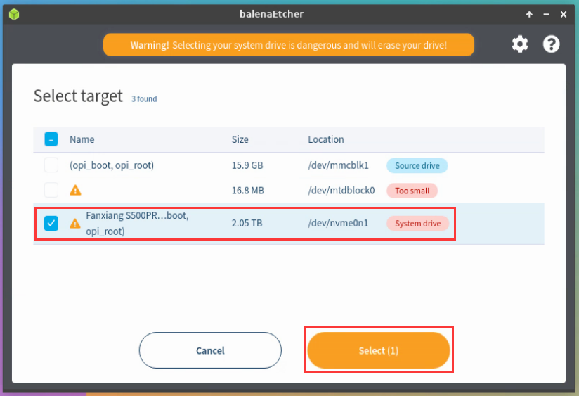
- Then click Flash
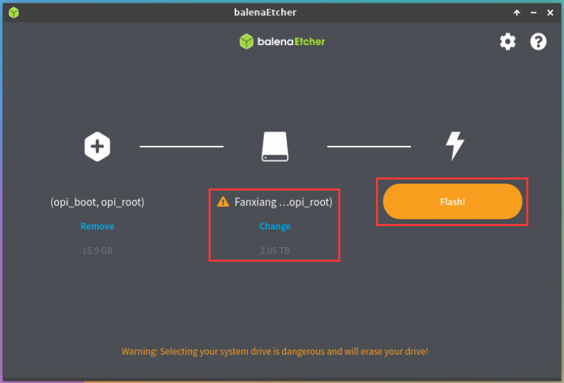
- Then click Yes, I’m sure
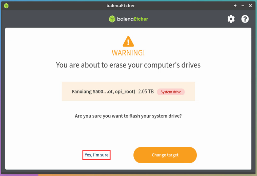
- Then enter the password orangepi for the development board Linux system and start burning the Linux image to the SSD
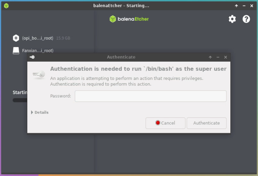
- The burning process is shown as follows:
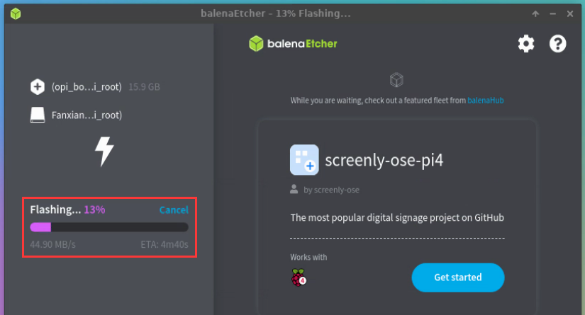
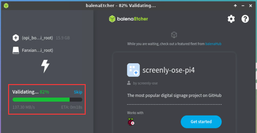
- The display after burning is as follows:
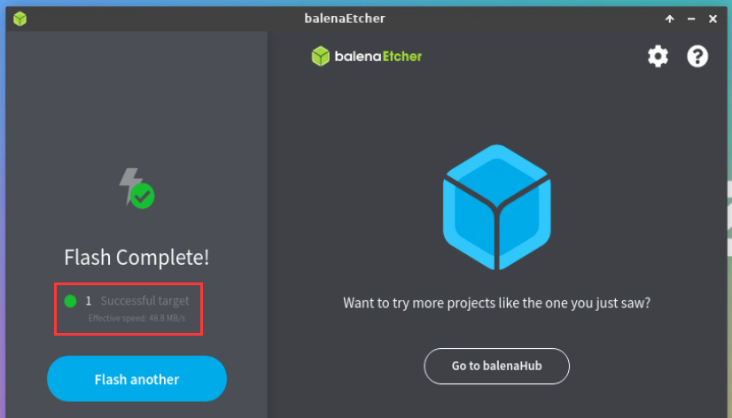
To expand the capacity of the rootfs partition on the NVMe SSD, perform the following steps:
a) First, open GParted. If Gparted is not pre-installed, run apt command to install it
orangepi@orangepi:~$ sudo apt-get install -y gparted

- b) Then enter the password orangepi for Linux and click Authenticate
c) Then click Fix
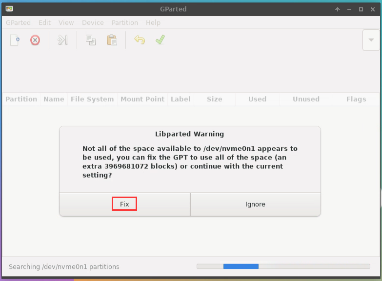
d) Then select NVMe SSD
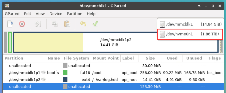
- e) The following information is displayed after the NVMe SSD is selected:
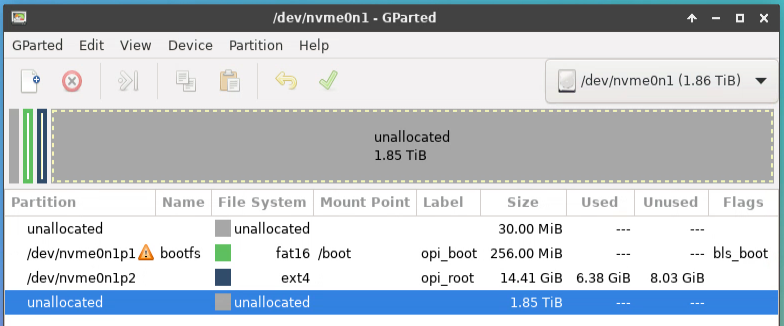
- f) Then select the /dev/nvme0n1p2 partition, right-click, and select Resize/Move
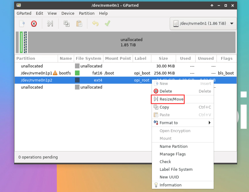
g) Then drag the capacity to the maximum as shown in the image below
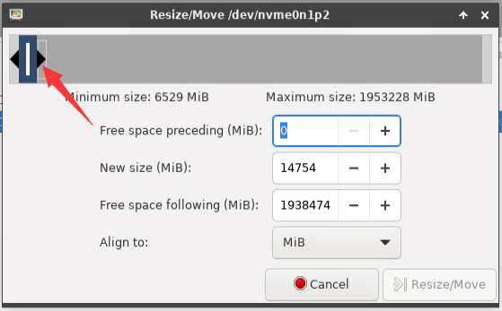
h) Then click Resize/Move
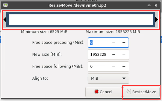
i) Then click on the green√ in the picture below
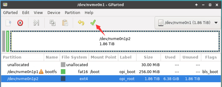
j) Then click Apply
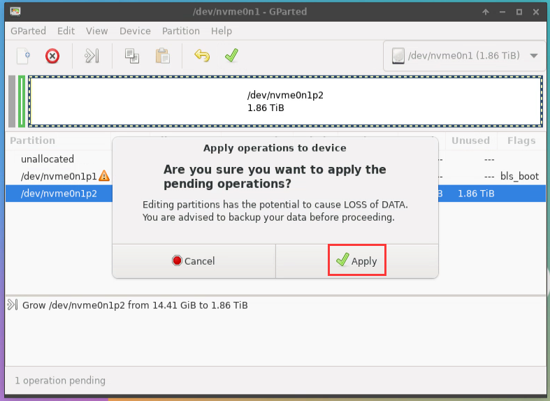
k) Then click Close to close it
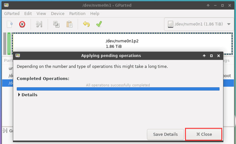
- At this point, you can shut it down using the sudo poweroff command. Then, pull out the TF card, press the power button again, and then start the Linux system in the SPIFlash+NVMe SSD.


The 9 step is to clone the system in the TF card to the NMVe SSD, we can also directly burn the Linux image file to the NVMe SSD, here roughly say the following steps:
Upload the Linux image file to the Linux operating system on the development board
Then use balenaEtcher to burn
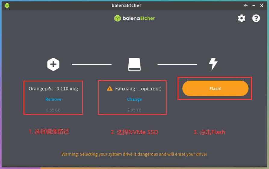
There is no need to manually expand the capacity after burning the image using this method. The first startup will automatically expand the capacity.

Method of burning Android image to TF card
Method of burning Android image to TF card through USB2.0 burning port
First prepare an 8GB or larger capacity TF card, TF card transmission speed must be class10 or above, it is recommended to use Sandisk and other brands of TF card
Also need to prepare a good quality USB2.0 public to public data cable
Then download the Rockchip DriverAssitant_v5.12.zip and the burning tool RKDevTool_Release_v3.15.zip from Orange Pi's data download page
On the Orange Pi's Data download page, first select the official tool and then go to the following folder
Then download all the files below
Then download the Android image from Orange Pi's Data download page.
After opening the download link of Android image, you can see the following two types of Android image. Please select TF card and eMMC image folder to start the image download
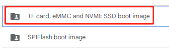
After entering the TF card and eMMC to start the image folder, you can see the following two images, their differences are:
The first image is dedicated to HDMI display and supports 4K display, if you do not use LCD screen, please download the image without lcd
If you want to use an lcd screen, select an image with lcd
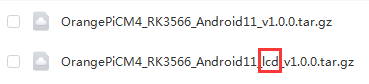
Then use the decompression software to decompress the compressed package of the downloaded Android image. In the decompressed file, the file ending with ".img "is the Android image file, the size of which is more than 1GB
Then use the decompression software to decompress DriverAssitant_v5.12.zip, and then find the DriverInstall.exe executable file in the decompressed folder and open it
Open DriverInstall.exe and install the SWick micro driver as follows
Click the "Driver Installation" button
Wait for a period of time, the pop-up window will prompt "Driver installation successful", and then click the "OK" button
Then decompress RKDevTool_Release_v3.15.zip, this software does not need to be installed, find RKDevTool in the decompressed folder and open it
After opening the RKDevTool burning tool, because the computer has not connected to the development board through the USB2.0 public-to-public data cable at this time, the lower left corner will display "No device found".
Then start burning Android image to TF card
First, connect the development board to the Windows computer through the USB2.0 male-to-public data cable. The position of the USB2.0 burning interface on the development board is shown in the figure below
Then make sure that no TF card is inserted into the development board and no power is connected
Then press and hold the MaskROM button on the development board. The position of the MaskROM button on the development board is shown as follows:
Connect the development board to the Type-C port, and power on the development board
If the previous steps are smooth, the development board will enter MASKROM mode at this time, and the interface of the burning tool will prompt "Found a MASKROM device".
Then insert the TF card into the development board
Then select Advanced features
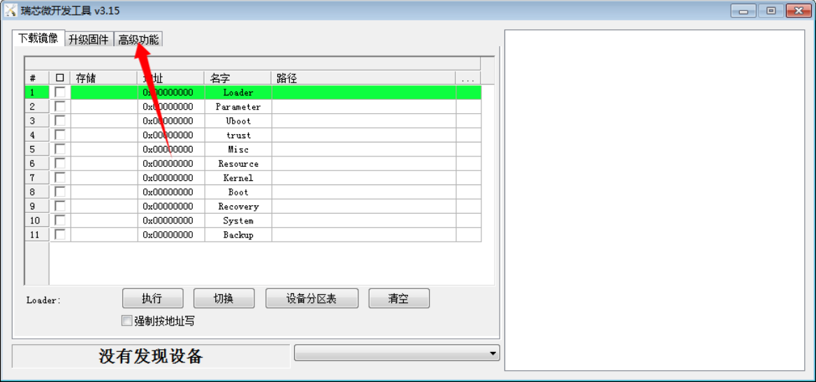
Then click on the location shown in the image below
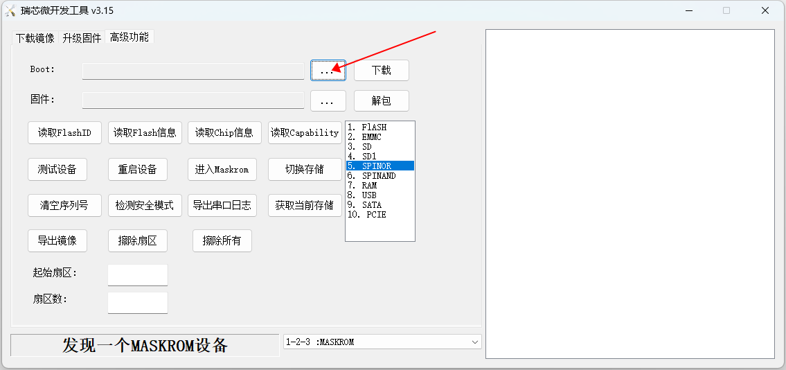
Select MiniLoaderAll.bin from the MiniLoader folder downloaded earlier and click Open
Then click Download
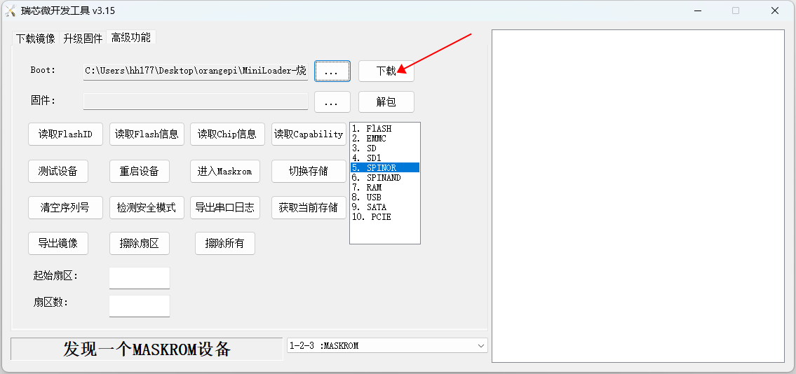
The following figure is displayed after MiniLoaderAll.bin is downloaded
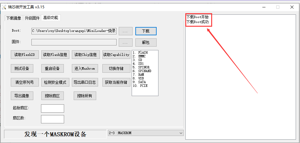
Then select the storage device as SD and click Switch storage
If the switchover is successful, the following figure is displayed
Then click on the "Upgrade Firmware" section of the burning tool
Then click the "Firmware" button to select the path of the Android image that you want to burn
Finally, click the "Upgrade" button to start burning. The log in the burning process is shown below. The Android system will start automatically after the burning is complete.
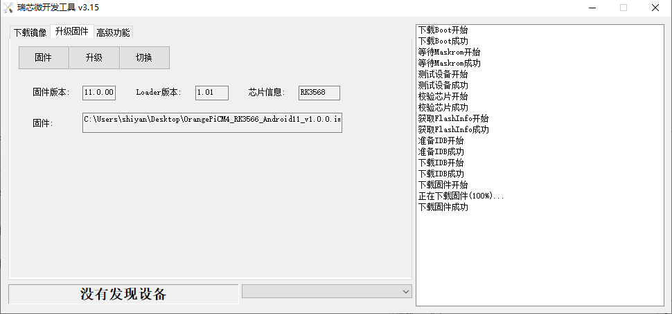


Method of burning Android image into eMMC
Method of burning Android image into eMMC through USB2.0 burning port
|
Note that all operations below are performed on a Windows computer. |
First you need to prepare a good quality USB2.0 male-to-male data cable
Then download Rockchip driver DriverAssitant_v5.12.zip and burning tool RKDevTool_Release_v3.15.zip from Orange Pi's data download page
Then download the Android image from the Orange Pi download page.
After opening the download link of the Android image, you can see the following two types of Android images. Please select the image in the TF card and eMMC boot image folder to download.
After entering the TF card and eMMC boot image folders, you can see the following two images. The difference between them is:
The first image is dedicated to HDMI display and supports 4K display. If you don’t use LCD screen, please download the image without lcd
If you want to use an LCD screen, please choose the image with LCD
Then use decompression software to decompress the compressed package of the downloaded Android image. In the decompressed file, the file ending with ".img" is the Android image file, with a size of more than 1GB.
Then use decompression software to decompress DriverAssitant_v5.12.zip, then find the DriverInstall.exe executable file in the decompressed folder and open it.
Open DriverInstall.exe and install the Rockchip microdriver as follows
Click the "Driver Installation" button
After waiting for a period of time, a window will pop up prompting "Driver installation successful", then click the "OK" button.
Then unzip RKDevTool_Release_v3.15.zip. This software does not need to be installed. Just find RKDevTool in the unzipped folder and open it.
After opening the RKDevTool burning tool, because the computer has not connected to the development board through the USB2.0 male-to-male data cable at this time, the lower left corner will prompt "No device found"
Then start burning the Android image into eMMC
First, connect the development board to the Windows computer through a USB2.0 male-to-male data cable. The location of the development board’s USB2.0 burning interface is as shown in the figure below.
Then make sure that the development board is not inserted into the TF card and not connected to the power supply
Then press and hold the MaskROM button on the development board, the position of the MaskROM button on the development board is shown in the figure below:
Then connect the development board to the power supply of the Type-C interface and power on
If the previous steps are successful, the development board will enter the MASKROM mode at this time, and the interface of the burning tool will prompt "found a MASKROM device"
Then please select advanced functions
Then click the position shown in the figure below
Then select MiniLoaderAll.bin in the MiniLoader folder downloaded earlier, and then click Open
Then click Download
The display after downloading MiniLoaderAll.bin is shown in the figure below
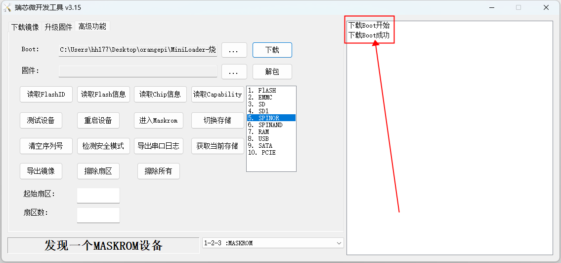
Then select the storage device as EMMC, and then click Switch Storage
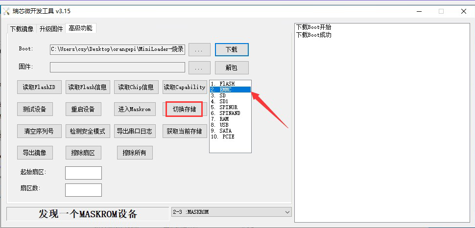
The successful switching is displayed as shown below
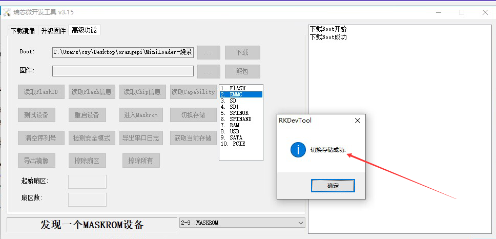
Then click the "Upgrade Firmware" column of the burning tool
Then click the "Firmware" button to select the path of the Android image that needs to be burned.
Finally, click the "Upgrade" button to start burning. The log during the burning process is as shown below. After burning is completed, the Android system will start automatically.


How to burn the Android11 image into EMMC through the TF card
|
Note that all of the following operations are performed in Windows computers. |
It is also necessary to prepare a 8GB or larger TF card. The transmission speed of the TF card must be class10 or more. It is recommended to use TF cards from brands such as SanDisk.
Then use the card reader to insert the TF card into the computer
Then download the SDDiskTool burn tool from Orange PI's data download page, please make sure that the version of the SDDiskTool tool is the latest V1.72
Then download the image of Android from Orange Pi's data download page
After turning on the download link of the Android image, you can see the two types of Android images below. Please select the image in the TF card and EMMC startup image folder for download
After entering the TF card and EMMC startup image folder, you can see the following two mirrors. The difference between them is:
a) The first image is specifically used for HDMI display. It supports 4K display. If you do not use the LCD screen, download the image without LCD
b) If you want to use the LCD screen, select the image with LCD
Then use the decompression software to decompress the downloaded Android image compressed package. In the files that are decompressed, the file ending with ".img" is the Android image file with a memory of more than 1GB
Then use the decompression software to decompress the SDDiskTool_v1.72.zip. This software does not need to be installed. Find the SD_Firmware_Tool.exe in the unzipped folder and open it.
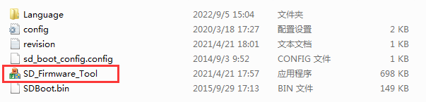
After opening SDDiskTool, if the TF card is recognized normally, the inserted disk device will be displayed in the "Select Removable Disk Device" column. Please make sure that the displayed disk device is consistent with the drive letter of the TF card you want to burn. If there is no display, you can try to unplug the TF card
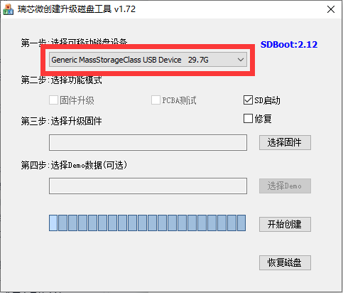
After confirming the drive letter, you can format the TF card first and click the Recover Disk button in SDDiskTool. You can also use the SD Card Formatter mentioned earlier to format the TF card
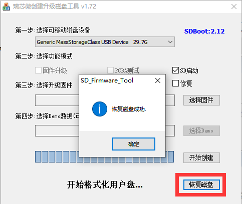
Then start writing the Android image to the TF card
First confirm that the displayed drive letter is the drive letter corresponding to the TF card under "Select Removable Disk Device"
Then select "Firmware Upgrade" in "Select Function Mode"
Then select the path of the Android firmware in the "Select Upgrade Firmware" column
Finally, click the "Start Creating" button to start burning.
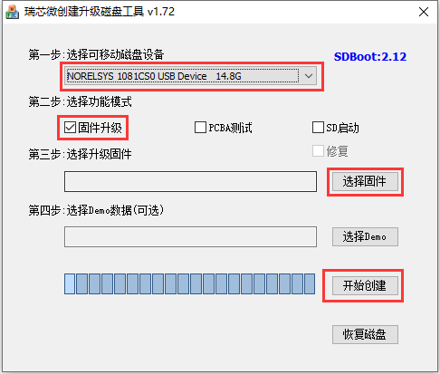
After the burning is completed, the display is as shown below, and then you can exit SDDiskTool
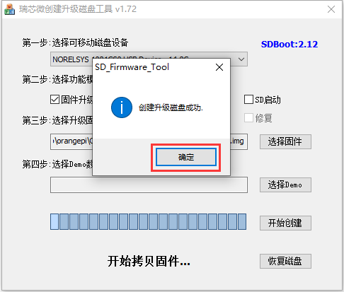
Then pull out the TF card from the computer and insert it into the development board. After the development board is powered on, it will automatically start burning the Android image in the TF card into the eMMC of the development board.
If the development board is connected to an HDMI display, you can also see the progress bar of burning the Android image to eMMC from the HDMI display
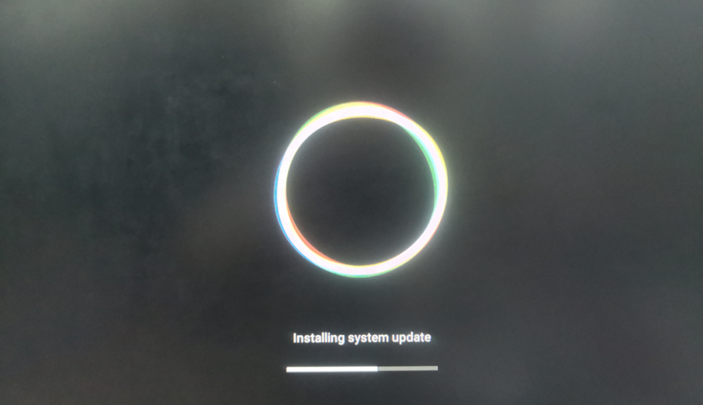
When the HDMI monitor displays the following information, it means that the burning of the Android image into the eMMC has been completed. At this time, the TF card can be pulled out, and then the Android system in the eMMC will start.
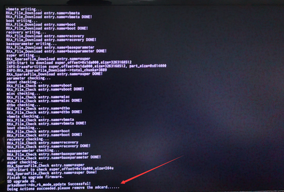


How to burn Android image to SPIFlash+NVMe SSD
|
Before starting to burn the image, you must make sure that the development board has been pasted with the SPI Flash chip, because the development board is not pasted with the SPI Flash chip when it leaves the factory, so it needs to be purchased and soldered on by yourself. The SPI Flash chip model we recommend is XM25QU128CWIQT08Q |
|
Since the startup priority of eMMC is higher than that of NVMe SSD, the system of eMMC needs to be cleared before burning the image. For the method of clearing eMMC, please refer to the instructions in the section "How to Clear eMMC Using RKDevTool" |
|
Note that all the following operations are performed on a Windows computer |
First you need to prepare an NVMe SSD solid state drive
The M.2 2230 SSD is as follows
The M.2 2242 specification SSD is as follows
Then insert the NVMe SSD into the M.2 PCIe interface of the development board and fix it
Please make sure that the SPI Flash has been attached to the development board. The location of the SPI Flash on the development board is as shown in the picture below. No other settings are required before starting burning
You also need to prepare a good quality USB2.0 male-to-male data cable
Then download the Rockchip microdriver DriverAssitant_v5.12.zip and the burning tool RKDevTool_Release_v3.15.zip from the Orange Pi data download page.
Then download the image of Android11
After opening the download link of the Android image, you can see the following two types of Android images. Please select the image in the SPIFlash-NVME SSD boot image folder to download
After entering the SPIFlash-NVME SSD boot image folder, you can see the following two images. The difference between them is:
a) The image without lcd is specially used for HDMI display and supports 4K display. If you don’t use the LCD screen, please download the image without lcd
b) If you want to use an LCD screen, please choose the image with lcd
Then use decompression software to decompress DriverAssitant_v5.12.zip, then find the DriverInstall.exe executable file in the decompressed folder and open it.
The steps to install the Rockchip driver after opening DriverInstall.exe are as follows
Click the "Driver Installation" button
After waiting for a period of time, a window will pop up prompting "Driver installation successful", then click the "OK" button
Then unzip RKDevTool_Release_v3.15.zip. This software does not need to be installed. Just find RKDevTool in the unzipped folder and open it
After opening the RKDevTool burning tool, because the computer has not yet connected to the development board through the USB2.0 male-to-male data cable, a message "No device found" will appear in the lower left corner.
Then start burning the Android image to SPIFlash+NVMe SSD
First, connect the development board to the Windows computer through a USB2.0 male-to-male data cable. The location of the USB2.0 programming port on the development board is as shown in the figure below.
Make sure that the development board is not inserted into the TF card and not connected to the power supply
Then press and hold the MaskROM button on the development board. The location of the MaskROM button on the development board is as shown in the figure below:
Then connect the development board to the power supply of the Type-C interface, power it on, and then release the MaskROM button
If the previous steps are successful, the development board will enter the MASKROM mode at this time, and the interface of the burning tool will prompt "Found a MASKROM device "
Then click the "Upgrade Firmware" column of the burning tool
Then click the "Firmware" button to select the Android image that needs to be burned
Finally, click the "Upgrade" button to start burning. The burning process is shown in the figure below. You can see that the firmware will be burned into SPIFlash first, and then burned into PCIE. The Android system will start automatically after burning.
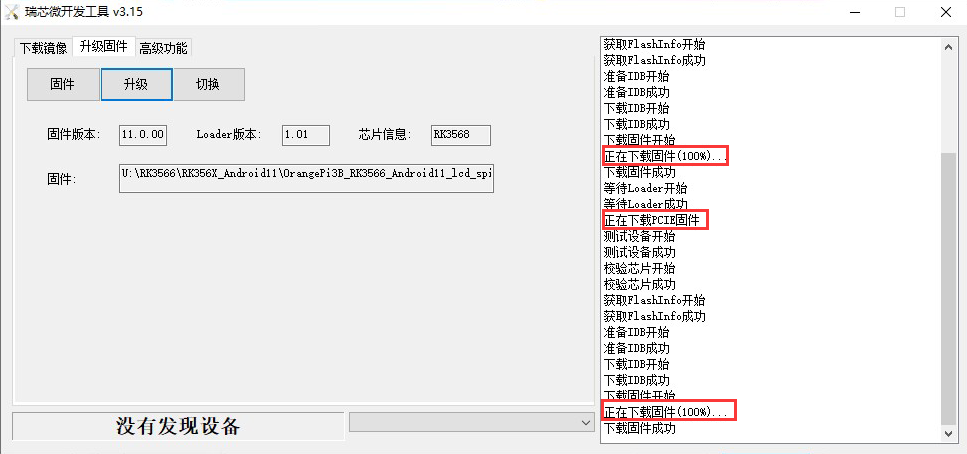


How to clear SPIFlash using RKDevTool
|
There is no SPI Flash chip on the development board when it leaves the factory, so it needs to be pasted by yourself. The model of the SPI Flash chip we recommend is XM25QU128CWIQT08Q |
The location of SPI Flash on the development board is shown in the figure below
First of all, you need to prepare a good quality USB2.0 male-to-male data cable
Then download the Rockchip driver DriverAssitant_v5.12.zi and MiniLoade and the burning tool RKDevTool_Release_v3.15.zip from the Orange Pi data download page
On the Orange Pi data download page, first select the official tool, and then enter the folder below
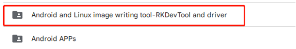
Then download all the files below
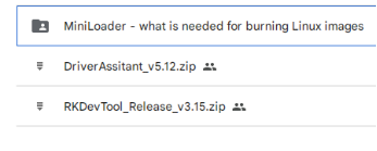
Note that the "MiniLoader-things needed to burn Linux images" folder will be referred to as the MiniLoader folder below
Then use decompression software to decompress DriverAssitant_v5.12.zip, then find the DriverInstall.exe executable file in the decompressed folder and open it
The steps to install the Rockchip driver after opening DriverInstall.exe are as follows
Click the "Driver Installation" button
After waiting for a period of time, a pop-up window will prompt "Driver installed successfully", and then click the "OK" button.
Then unzip RKDevTool_Release_v3.15.zip. This software does not need to be installed. Just find RKDevTool in the unzipped folder and open it.
After opening the RKDevToolburning tool, because the computer has not yet connected to the development board through the USB2.0 male-to-male data cable, a message "No device found" will appear in the lower left corner.
Then you can start to clear the contents of the SPI FLASH
First, connect the development board to the Windows computer through a USB2.0 male-to-male data cable. The location of the USB2.0 programming port on the development board is as shown in the figure below.
Make sure that the development board is not inserted into the TF card and not connected to the power supply
Then press and hold the MaskROM button on the development board. The location of the MaskROM button on the development board is as shown in the figure below:
Then connect the development board to the power supply of the Type-C interface, power it on, and then release the MaskROM button.
If the previous steps are successful, the development board will enter the MASKROM mode at this time, and the interface of the burning tool will prompt "found a MASKROM device"
Then please select advanced functions
Then click the position shown in the figure below
Then select MiniLoaderAll.bin in the MiniLoader folder downloaded earlier, and then click Open
Then click Download
The display after downloading MiniLoaderAll.bin is shown in the figure below
Then select the storage device as SPINOR
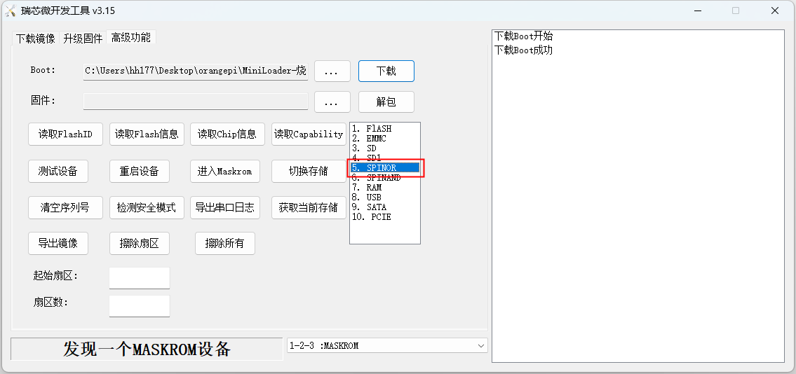
Then click switch storage
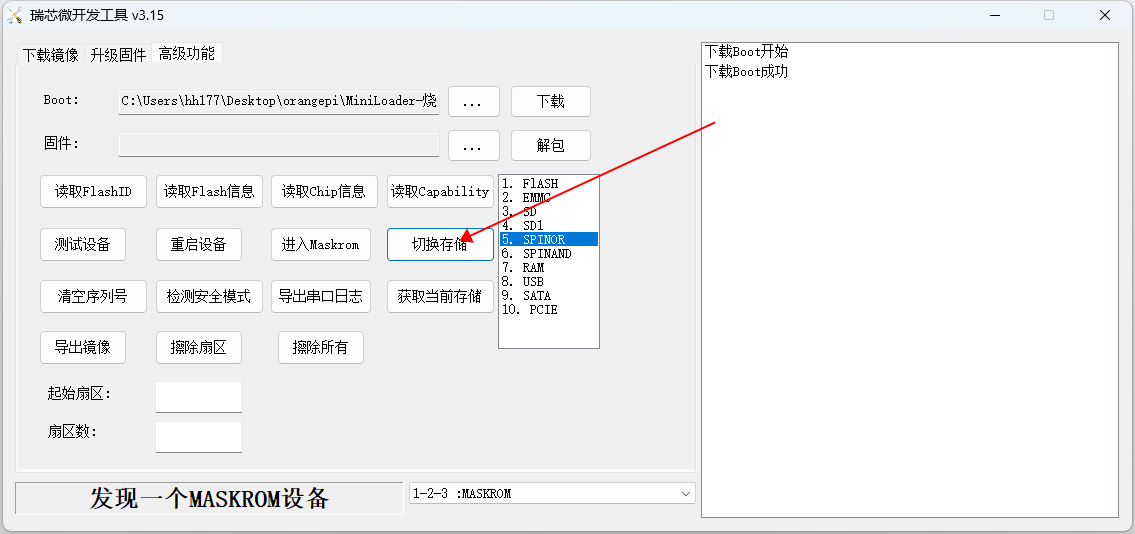
Then click Erase All and it will start erasing SPIFlash.
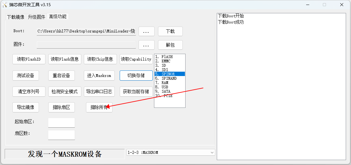
The display log after erasing SPIFlash is shown in the figure below
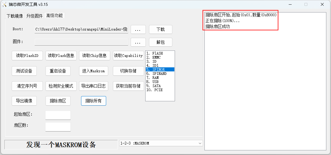


How to clear eMMC using RKDevTool
First you need to prepare a good quality USB2.0 male-to-male data cable
Then download the Rockchip microdriver DriverAssitant_v5.12.zip and MiniLoader and the burning tool RKDevTool_Release_v3.15.zip from the Orange Pi data download page
On the Orange Pi data download page, first select the official tool, and then enter the folder below
Then download all the files below
Note that the "MiniLoader-things needed to burn the Linux image" folder is hereinafter referred to as the MiniLoader folder.
Then use the decompression software to decompress DriverAssitant_v5.12.zip, and then find the DriverInstall.exe executable file in the decompressed folder and open it
After opening DriverInstall.exe, the steps to install the Rockchip driver are as follows
Click the "Driver Installation" button
After waiting for a period of time, a window will pop up prompting "Driver installation successful", then click the "OK" button.
Then unzip RKDevTool_Release_v3.15.zip. This software does not need to be installed. Just find RKDevTool in the unzipped folder and open it.
After opening the RKDevTool burning tool, because the computer has not connected to the development board through the USB2.0 male-to-male data cable at this time, the lower left corner will prompt "No device found"
Then you can start to clear the content in eMMC
First, connect the development board to the Windows computer through a USB2.0 male-to-male data cable. The location of the USB2.0 programming port on the development board is as shown in the figure below.
Make sure that the development board is not inserted into the TF card and not connected to the power supply
Then press and hold the MaskROM button on the development board. The location of the MaskROM button on the development board is as shown in the figure below:
Then connect the development board to the power supply of the Type-C interface, power it on, and then release the MaskROM button
If the previous steps are successful, the development board will enter the MASKROM mode at this time, and the interface of the burning tool will prompt "found a MASKROM device"
Then please select advanced functions
Then click the position shown in the figure below
Then select MiniLoaderAll.bin in the MiniLoader folder downloaded earlier, and then click Open
Then click Download
The display after downloading MiniLoaderAll.bin is shown in the figure below
Then select the storage device as eMMC
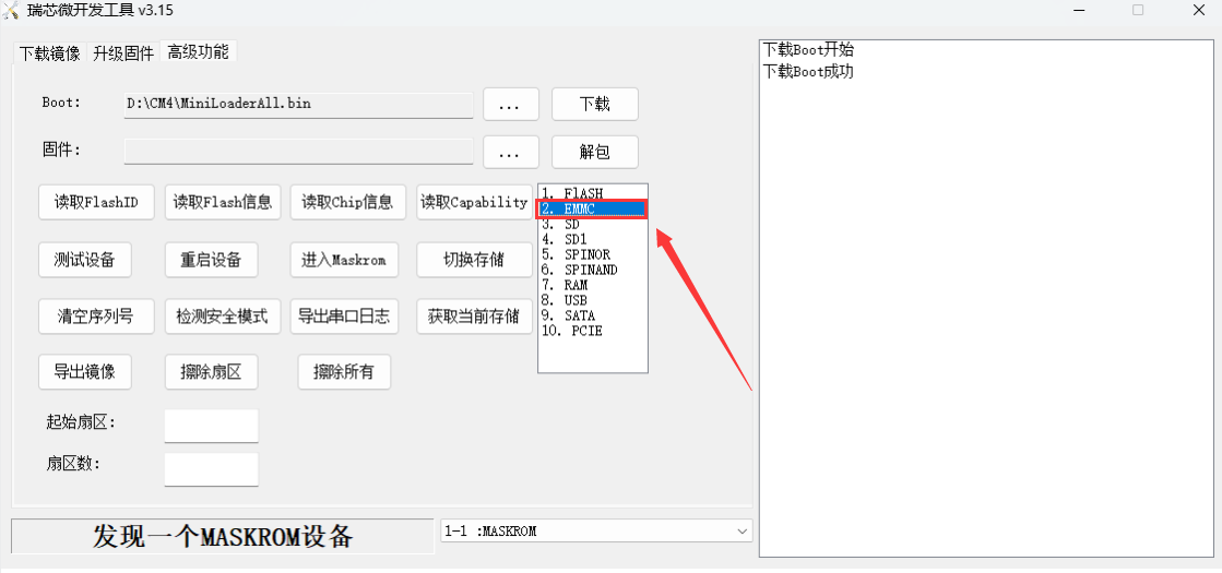
Then click switch storage
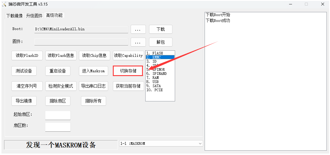
Then click Erase All to start erasing the eMMC.
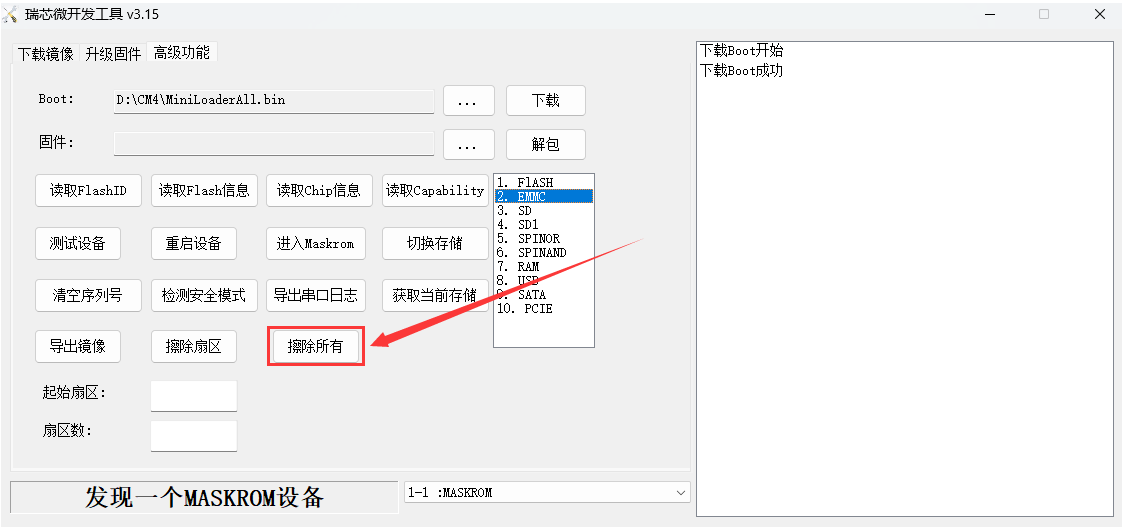
The display log after erasing eMMC is as shown below
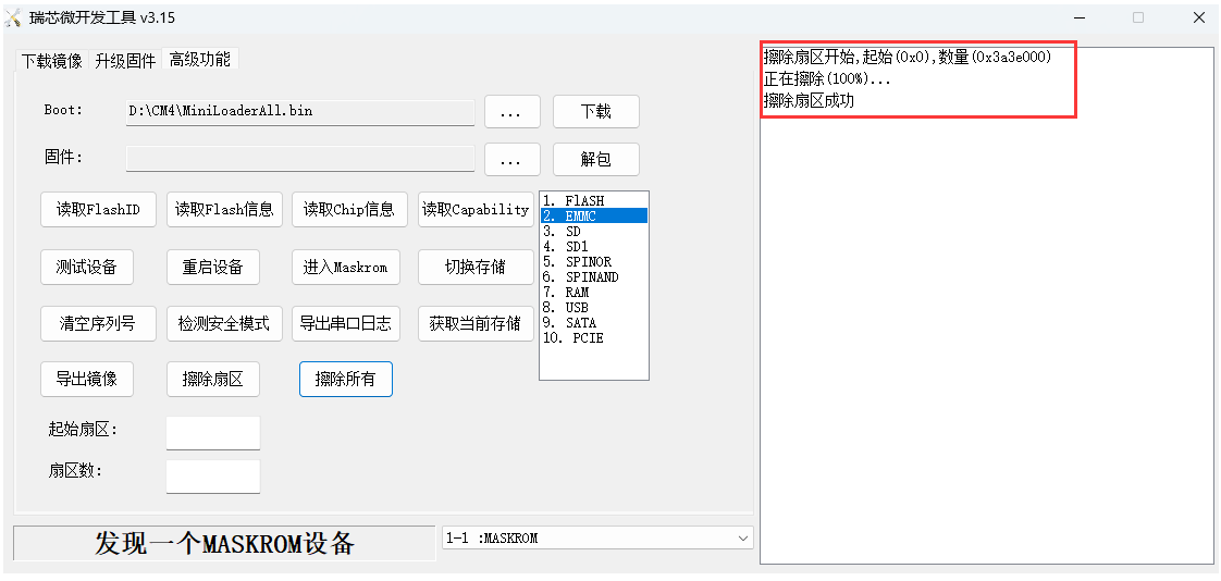


Boot the Orange Pi development board
First install the Orange Pi CM4 core board on the base board
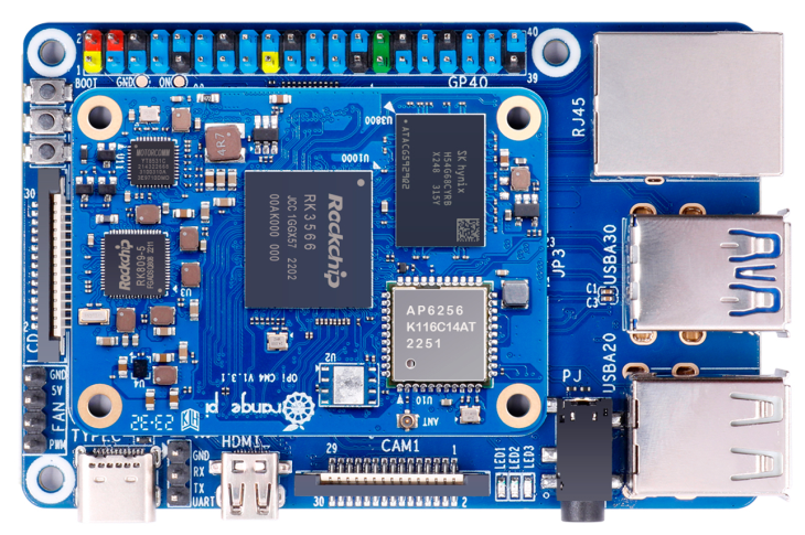
Then insert the TF card with the burned image into the TF card slot of the Orange Pi development board.
The development board has a Micro HDMI interface, and the development board can be connected to a TV or HDMI display through a Micro HDMI to HDMI cable. If you have purchased an LCD screen, you can also use the LCD screen to display the system interface of the development board
Connect a USB mouse and keyboard to control the Orange Pi development board
The development board has an Ethernet port, which can be plugged into a network cable to access the Internet
Connect a high-quality power adapter with a 5V/3A USB Type-C interface.
Remember not to plug in a power adapter with a voltage output greater than 5V, it will burn out the development board.
Many unstable phenomena during system power-on and startup are basically caused by power supply problems, so a reliable power adapter is very important. If you find that you are constantly restarting during the startup process, please replace the power supply or Type-C data cable and try again.
Type-C power interface does not support PD negotiation.
In addition, please do not connect to the USB interface of the computer to power the development board.

Then turn on the switch of the power adapter. If everything is normal, you can see the startup screen of the system on the HDMI monitor or LCD screen.
If you want to view the output information of the system through the debugging serial port, please use the serial port cable to connect the development board to the computer. For the connection method of the serial port, please refer to the section on how to use the debugging serial port
How to use the debugging serial port
Connection instruction of debugging serial port
- First, you need to prepare a 3.3VUSB to TTL module, and then insert the USB interface end of the USB to TTL module into the USB interface of the computer.
For better compatibility, it is recommended to use CH340 USB to TTL module, please do not use CP2102, PL2303 type USB to TTL module.
Before purchasing a USB to TTL module, please confirm that the module supports a baud rate of 1500000.

The corresponding relationship between the GND, RXD and TXD pins of the development board’s debugging serial port is as shown in the figure below
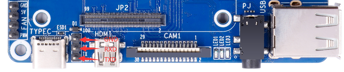
The GND, TXD and RXD pins of the USB to TTL module need to be connected to the debugging serial port of the development board through Dupont lines
Connect the GND of the USB to TTL module to the GND of the development board
The RX of the USB to TTL module is connected to the TX of the development board
The TX of the USB to TTL module is connected to the RX of the development board
The schematic diagram of connecting the USB to TTL module to the computer and Orange Pi development board is as shown below
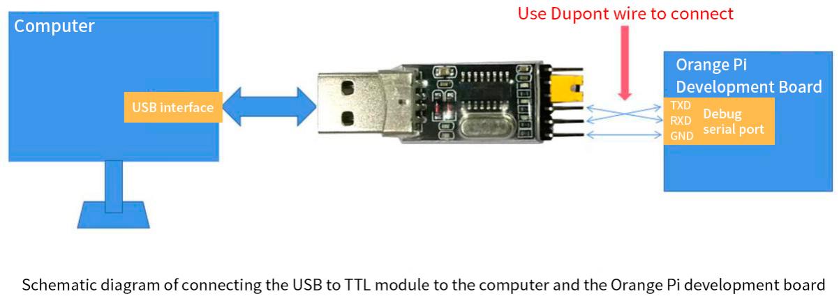
The TX and RX of the serial port need to be cross-connected. If you don’t want to carefully distinguish the order of TX and RX, you can connect the TX and RX of the serial port casually. If there is no output in the test, then exchange the order of TX and RX, so that there is always a The order is correct


How to use the debugging serial port on Ubuntu platform
|
There are many serial port debugging software that can be used under Linux, such as putty, minicom, etc. The following demonstrates how to use putty. |
First insert the USB to TTL module into the USB interface of the Ubuntu computer. If the USB to TTL module is connected and recognized normally, you can see the corresponding device node name under /dev of the Ubuntu PC. Remember this node name and set the serial port later. software will be used.
test@test:~$ ls /dev/ttyUSB*
/dev/ttyUSB0
Then use the following command to install putty on Ubuntu PC
test@test:~$ sudo apt-get update
test@test:~$ sudo apt-get install -y putty
Then run putty, remember to add sudo permissions
test@test:~$ sudo putty
After executing the putty command, the following interface will pop up
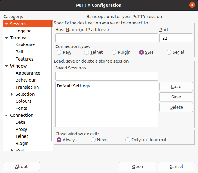
First select the serial port setting interface
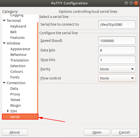
Then set the parameters of the serial port
Set the Serial line to connect to to /dev/ttyUSB0 (modify to the corresponding node name, usually /dev/ttyUSB0)
Set Speed(baud) to 1500000 (the baud rate of the serial port)
Set Flow control to None
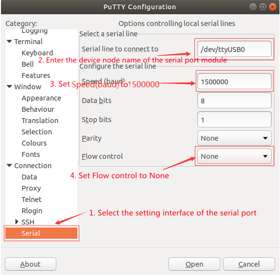
After setting up the serial port setting interface, return to the Session interface.
First select the Connection type as Serial
Then click theOpen button to connect to the serial port
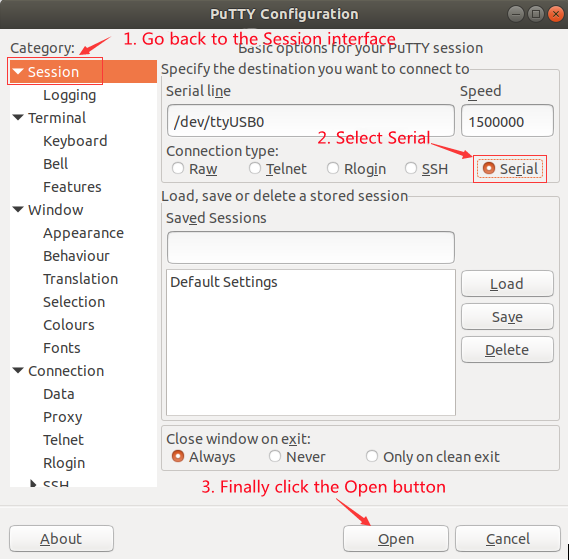
After starting the development board, you can see the Log information output by the system from the open serial terminal.
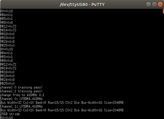


How to use the debugging serial port on Windows platform
|
There are many serial port debugging software that can be used under Windows, such as SecureCRT, MobaXterm, etc. The following demonstrates how to use MobaXterm. This software has a free version and can be used without buying a serial number. |
Download MobaXterm
Download MobaXterm website as follows
After entering the MobaXterm download page, click GET XOBATERM NOW!
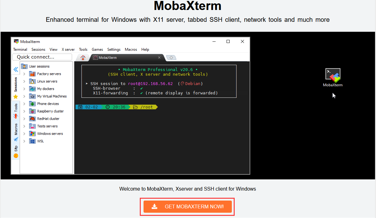
Then choose to download the Home version
Then select the Portable version. There is no need to install it after downloading. You can open it directly and use it.
After downloading, use decompression software to decompress the downloaded compressed package to get the MobaXterm executable software, and then double-click to open it.
After opening the software, the steps to set up the serial port connection are as follows
Open the session settings interface
Select the serial port type
Select the port number of the serial port (select the corresponding port number according to the actual situation). If you cannot see the port number, please use 360 Driver Master to scan and install the driver for the USB to TTL serial port chip.
Select the baud rate of the serial port to be 1500000
Finally click the "OK" button to complete the setup


After clicking the "OK" button, you will enter the following interface. At this time, you can see the output information of the serial port
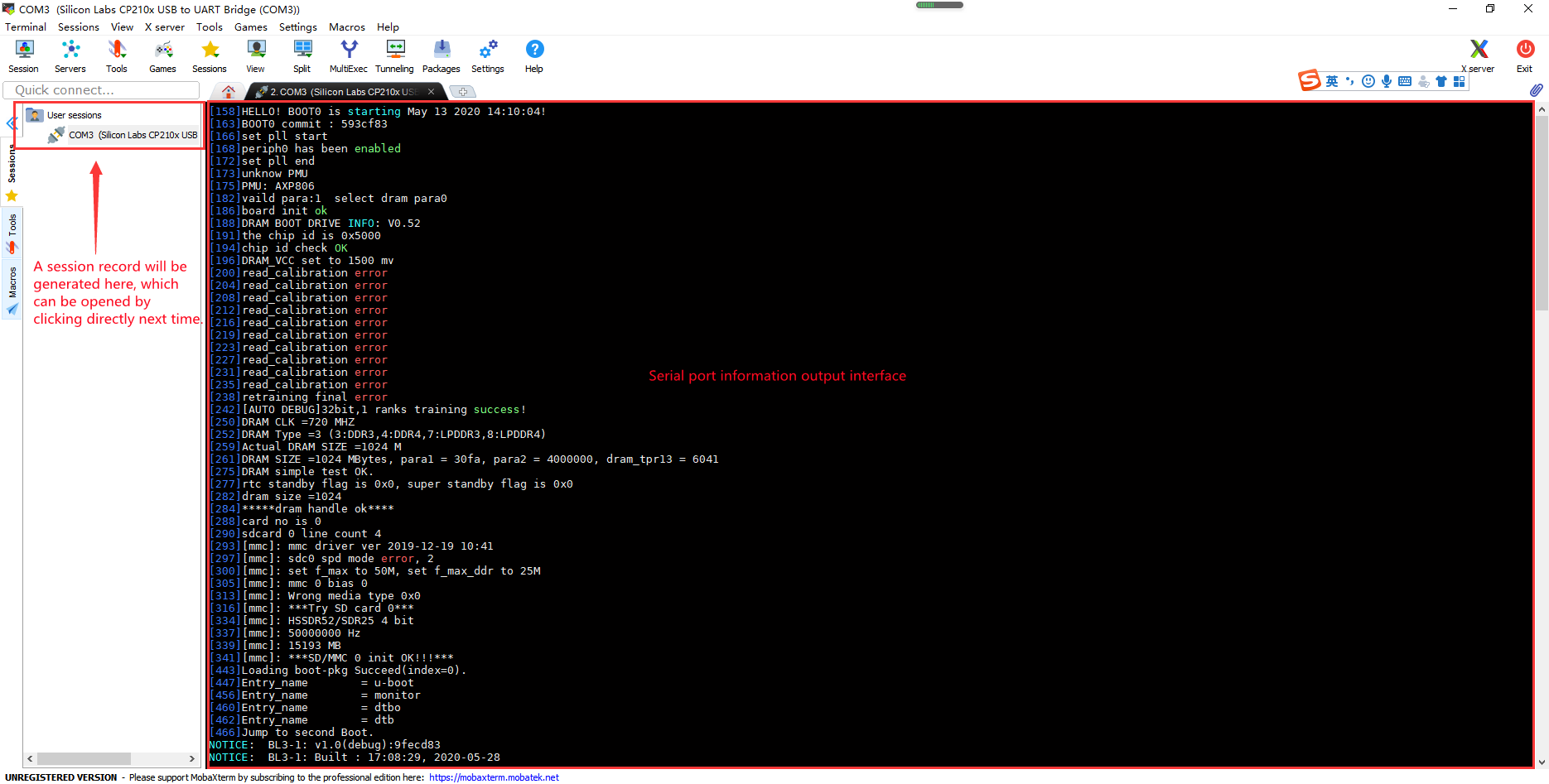

Instructions for using the 5v pin in the 40pin interface of the development board to supply power
|
The power supply method we recommend for the development board is to use the 5V/3A Type C interface power cord to plug into the Type-C power interface of the development board. If you need to use the 5V pin in the 40-pin interface to power the development board, please ensure that the power cord and power adapter used can meet the power supply requirements of the development board. If the use is unstable, please switch to Type-C power supply. |
First you need to prepare a power cord as shown in the picture below

The power cord shown in the figure above can be bought on Taobao, please search for purchase by yourself.
Use the 5V pin in the 40pin interface to power the development board. The power cord connection is as follows
The USB A port of the power cord shown in the picture above needs to be plugged into the 5V/3A power adapter connector.(Please do not plug it into the USB port of your computer for power supply)
The red DuPont line needs to be plugged into the 5V pin of the development board 40pin
The black DuPont wire needs to be plugged into the GND pin of the 40pin interface
The position of the 40Pin interface 5V pin and GND pin in the development board is shown in the figure below, Remember not to reverse
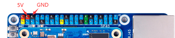


Ubuntu/Debian Server and Xfce desktop system instructions
|
The content of this chapter is written based on the Linux server version image and the xfce desktop version image. |
Supported Linux image types and kernel versions
| Linux image type | Kernel version | server version | desktop version |
| Debian 11 - Bullseye | Linux5.10 | support | support |
| Debian12 - Bookworm | Linux5.10 | support | support |
| Ubuntu 20.04 - Focal | Linux5.10 | support | support |
| Ubuntu 22.04 - Jammy | Linux5.10 | support | support |
Linux system adaptation situation
| Function | Debian11 | Debian12 | Ubuntu20.04 | Ubuntu22.04 |
| USB2.0x3 | OK | OK | OK | OK |
| USB3.0x1 | OK | OK | OK | OK |
| M.2 NVMe SSD Boot | OK, you need to attach SPI Flash to it for normal use. | |||
| WIFI | OK | OK | OK | OK |
| Bluetooth | OK | OK | OK | OK |
| GPIO(40pin) | OK | OK | OK | OK |
| UART(40pin) | OK | OK | OK | OK |
| SPI(40pin) | OK | OK | OK | OK |
| I2C(40pin) | OK | OK | OK | OK |
| PWM(40pin) | OK | OK | OK | OK |
| PWM fan interface | OK | OK | OK | OK |
| 3pin debugging serial port | OK | OK | OK | OK |
| EMMC | OK | OK | OK | OK |
| TF card startup | OK | OK | OK | OK |
| HDMI video | OK | OK | OK | OK |
| HDMI audio | OK | OK | OK | OK |
| OV5647 camera | Kernel driver is OK, 3A is not adjusted | |||
| LCD | OK | OK | OK | OK |
| eDP display | OK | OK | OK | OK |
| Gigabit Ethernet port | OK | OK | OK | OK |
| Network port status light | OK | OK | OK | OK |
| Headphone playback | OK | OK | OK | OK |
| headphone recording | OK | OK | OK | OK |
| LED light | OK | OK | OK | OK |
| GPU | OK | OK | OK | OK |
| NPU | OK | OK | OK | OK |
| VPU | OK | OK | OK | OK |
| watchdog test | OK | OK | OK | OK |
| Chromium hard decryption video | OK | OK | OK | OK |
Linux command format description in this manual
All commands that need to be entered in the Linux system in this manual will be enclosed in the following boxes
As shown below, the content in the yellow box indicates the content that needs special attention, except for the commands in it
Description of the prompt type in front of the command
The prompt in front of the command refers to the content of the red part in the box below. This part of the content is not part of the Linux command, so when entering the command in the Linux system, please do not enter the content of the red font part.
orangepi@orangepi:~$ sudo apt update
root@orangepi:~# vim /boot/boot.cmd
test@test:~$ ssh root@192.168.1.xxx
root@test:~# ls
root@orangepi:~$ The prompt indicates that this command is entered in the Linux system of the development board. The $ at the end of the prompt indicates that the current user of the system is an ordinary user. When executing a privileged command, sudo needs to be added.
root@orangepi:~# The prompt indicates that this command is entered in the Linux system of the development board, and the # at the end of the prompt indicates that the current user of the system is the root user, who can execute any desired command
test@test:~$ The prompt indicates that the command was entered in the Ubuntu PC or Ubuntu virtual machine, not the Linux system of the development board. The $ at the end of the prompt indicates that the current user of the system is an ordinary user. When executing privileged commands, sudo needs to be added.
root@test:~# The prompt indicates that the command was entered in the Ubuntu PC or Ubuntu virtual machine, not the Linux system of the development board. The # at the end of the prompt indicates that the current user of the system is the root user and can execute any command you want to execute.
What are the commands that need to be entered?
As shown below, the bold black part is the command that needs to be input. The content below the command is the output content (some commands have output, and some may not output). This part of the content does not need to be input
root@orangepi:~# cat /boot/orangepiEnv.txt
verbosity=7
bootlogo=false
console=serial
As shown below, some commands cannot be written in one line and will be placed on the next line. As long as the black and bold parts are all commands that need to be input. When these commands are entered into one line, the last "\" of each line needs to be removed, this is not part of the command. In addition, there are spaces in different parts of the command, please don't miss it
orangepi@orangepi:~$ echo \
"deb [arch=$(dpkg --print-architecture) \
signed-by=/usr/share/keyrings/docker-archive-keyring.gpg] \
https://download.docker.com/linux/debian \
$(lsb_release -cs) stable" | sudo tee /etc/apt/sources.list.d/docker.list > /dev/null
Linux system login instructions
Linux system default login account and password
| account | password |
| root | orangepi |
| orangepi | orangepi |
|
Note that when entering a password, the specific content of the entered password will not be displayed on the screen. Please do not think that there is something wrong. Just press Enter after entering it. |
|
When you are prompted for an incorrect password or there is a problem with the ssh connection, please note that as long as you are using the Linux image provided by Orange Pi, please do not suspect that the above password is incorrect, but look for other reasons. |
How to set up automatic login of Linux system terminal
The Linux system automatically logs in to the terminal by default. The default login user name is orangepi.
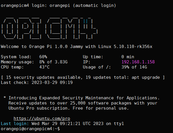
Use the following command to set the root user to automatically log in to the terminal
orangepi@orangepi:~$ sudo auto_login_cli.sh root
Use the following command to disable automatic login to the terminal
orangepi@orangepi:~$ sudo auto_login_cli.sh -d
Use the following command to set the orangepi user to automatically log in to the terminal again
orangepi@orangepi:~$ sudo auto_login_cli.sh orangepi

Instructions for automatic login of the Linux desktop version system
The desktop version system will automatically log in to the desktop after startup without entering a password.
Run the following command to prevent the desktop system from automatically logging into the desktop
orangepi@orangepi:~$ sudo disable_desktop_autologin.sh
Then restart the system and a login dialog box will appear. At this time, you need to enter a password to enter the system


The setting method of root user automatic login in Linux desktop version system
Execute the following command to set the desktop version of the system to automatically log in using the root user
orangepi@orangepi:~$ sudo desktop_login.sh root
Then restart the system, it will automatically use the root user to log in to the desktop
Note that if you use the root user to log in to the desktop system, you cannot use pulseaudio in the upper right corner to manage audio devices.
Also note that this is not a bug, since pulseaudio is not allowed to run as root.
Execute the following command to set up the desktop version of the system again to use orangepi user to automatically log in
orangepi@orangepi:~$ sudo desktop_login.sh orangepi

How to disable the desktop in Linux desktop system
First enter the following command in the command line, please remember to add sudo permission
orangepi@orangepi:~$ sudo systemctl disable lightdm.service
Then restart the Linux system and you will find that the desktop will not be displayed.
orangepi@orangepi:~$ sudo reboot
The steps to reopen the desktop are as follows:
First enter the following command in the command line, please remember to add sudo permission
orangepi@orangepi:~$ sudo systemctl start lightdm.service
After the command is executed, the desktop will be displayed
Onboard LED light test instructions
There are three LED lights on the development board, one green light, one red light, and one PCIe light. The location is shown in the figure below:
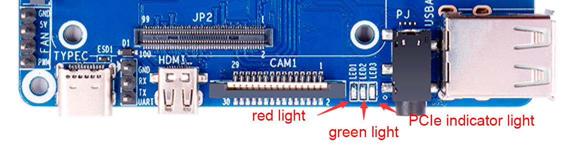
As long as the development board is powered on, the red LED light will always be on, which is controlled by the hardware and cannot be turned off by the software
The green LED light will keep flashing after the kernel is started, which is controlled by software
The PCIe indicator light will flash when there is data transmission on the PCIe interface.
The method of setting the green light to turn on and off and flash is as follows
Note that the following operations should be performed under the root user
First enter the setting directory of the green light
root@orangepi:~# cd /sys/class/leds/status_led
The command to set the green light to stop flashing is as follows:
root@orangepi:/sys/class/leds/status_led# echo none trigger
The command to set the green light to be always on is as follows:
root@orangepi:/sys/class/leds/status_led# echo default-on trigger
The command to set the green light flashing is as follows:
root@orangepi:/sys/class/leds/status_led# echo heartbeat trigger

Network connection test
Ethernet port test
First, plug one end of the network cable into the Ethernet interface of the development board, and the other end of the network cable into the router, and make sure the network is open.
After the system starts, it will automatically assign an IP address to the Ethernet card through DHCP, No other configuration is required
The command to view the IP address in the Linux system of the development board is as follows
orangepi@orangepi:~$ ip addr show eth0
2: eth0: <BROADCAST,MULTICAST,UP,LOWER_UP> mtu 1500 qdisc mq state UP group default qlen 1000
link/ether 4a:fe:2b:3d:17:1c brd ff:ff:ff:ff:ff:ff
inet 192.168.1.150/24 brd 192.168.1.255 scope global dynamic noprefixroute eth0
valid_lft 43150sec preferred_lft 43150sec
inet6 fe80::9a04:3703:faed:23be/64 scope link noprefixroute
valid_lft forever preferred_lft forever
When using ifconfig to check the IP address, if the following information is prompted, it is caused by not adding sudo. The correct command is: sudo ifconfig
orangepi@orangepi:~$ ifconfig
Command 'ifconfig' is available in the following places
* /sbin/ifconfig
* /usr/sbin/ifconfig
The command could not be located because '/sbin:/usr/sbin' is not included in the PATH environment variable.
This is most likely caused by the lack of administrative privileges associated with your user account.
ifconfig: command not found
There are three ways to check the IP address after the development board is started.:
1. Connect the HDMI display, then log in to the system and use the ip addr show eth0 command to view the IP address.
2. Enter the ip addr show eth0 command in the debugging serial terminal to view the IP address.
3. If there is no debugging serial port and no HDMI display, you can also check the IP address of the development board network port through the management interface of the router. However, in this method, some people often cannot see the IP address of the development board normally. If you can't see it, the debugging method is as follows:
First, check whether the Linux system has started normally. If the green light of the development board is flashing, it usually means that it has started normally. If only the red light is on, it means that the system has not started normally.;
Check whether the network cable is plugged in tightly, or try another network cable;
Try another router (I have encountered many problems with routers, such as the router being unable to assign an IP address normally, or the IP address being assigned normally but not visible in the router);
If there is no router to replace, you can only connect an HDMI display or use the debugging serial port to check the IP address.
In addition, it should be noted that the development board's DHCP automatic allocation of IP addresses does not require any settings.
The command to test the network connectivity is as follows, the ping command can be interrupted through the shortcut key of Ctrl+C
orangepi@orangepi:~$ ping www.baidu.com -I eth0
PING www.a.shifen.com (14.215.177.38) from 192.168.1.12 eth0: 56(84) bytes of data.
64 bytes from 14.215.177.38 (14.215.177.38): icmp_seq=1 ttl=56 time=6.74 ms
64 bytes from 14.215.177.38 (14.215.177.38): icmp_seq=2 ttl=56 time=6.80 ms
64 bytes from 14.215.177.38 (14.215.177.38): icmp_seq=3 ttl=56 time=6.26 ms
64 bytes from 14.215.177.38 (14.215.177.38): icmp_seq=4 ttl=56 time=7.27 ms
^C
--- www.a.shifen.com ping statistics ---
4 packets transmitted, 4 received, 0% packet loss, time 3002ms
rtt min/avg/max/mdev = 6.260/6.770/7.275/0.373 ms
WIFI connection test
|
Please do not connect to WIFI by modifying the /etc/network/interfaces configuration file. There will be problems in connecting to the WIFI network in this way. |
The server image connects to WIFI through commands
|
When the development board is not connected to Ethernet, not connected to HDMI display, but only connected to the serial port, it is recommended to use the commands demonstrated in this section to connect to the WIFI network. Because nmtui can only display characters in some serial port software (such as minicom) and cannot display the graphical interface normally. Of course, if the development board is connected to an Ethernet or HDMI display, you can also use the commands demonstrated in this section to connect to the WIFI network. |
First log in to the Linux system, there are three ways:
- If the development board is connected with a network cable, you can remotely log in to the Linux system through ssh
If the development board is connected to the debugging serial port, you can use the serial port terminal to log in to the Linux system
If the development board is connected to the HDMI display, you can log in to the Linux system through the terminal displayed on the HDMI
First use the nmcli dev wifi command to scan the surrounding WIFI hotspots
orangepi@orangepi:~$ nmcli dev wifi
Then use the nmcli command to connect to the scanned WIFI hotspot,
wifi_name needs to be replaced with the name of the WIFI hotspot you want to connect to
wifi_passwd needs to be replaced with the password of the WIFI hotspot you want to connect to
orangepi@orangepi:~$ nmcli dev wifi connect wifi_name password wifi_passwd
Device 'wlan0' successfully activated with 'cf937f88-ca1e-4411-bb50-61f402eef293'.
You can check the IP address of the wifi through the ip addr show wlan0 command
orangepi@orangepi:~$ ip addr show wlan0
11: wlan0: <BROADCAST,MULTICAST,UP,LOWER_UP> mtu 1500 qdisc pfifo_fast state UP group default qlen 1000
link/ether 23:8c:d6:ae:76:bb brd ff:ff:ff:ff:ff:ff
inet 192.168.1.11/24 brd 192.168.1.255 scope global dynamic noprefixroute wlan0
valid_lft 259192sec preferred_lft 259192sec
inet6 240e:3b7:3240:c3a0:c401:a445:5002:ccdd/64 scope global dynamic noprefixroute
valid_lft 259192sec preferred_lft 172792sec
inet6 fe80::42f1:6019:a80e:4c31/64 scope link noprefixroute
valid_lft forever preferred_lft forever
Use the ping command to test the connectivity of the wifi network, and the ping command can be interrupted through the shortcut key Ctrl+C
orangepi@orangepi:~$ ping www.orangepi.org -I wlan0
PING www.orangepi.org (182.92.236.130) from 192.168.1.49 wlan0: 56(84) bytes of data.
64 bytes from 182.92.236.130 (182.92.236.130): icmp_seq=1 ttl=52 time=43.5 ms
64 bytes from 182.92.236.130 (182.92.236.130): icmp_seq=2 ttl=52 time=41.3 ms
64 bytes from 182.92.236.130 (182.92.236.130): icmp_seq=3 ttl=52 time=44.9 ms
64 bytes from 182.92.236.130 (182.92.236.130): icmp_seq=4 ttl=52 time=45.6 ms
64 bytes from 182.92.236.130 (182.92.236.130): icmp_seq=5 ttl=52 time=48.8 ms
^C
--- www.orangepi.org ping statistics ---
5 packets transmitted, 5 received, 0% packet loss, time 4006ms
rtt min/avg/max/mdev = 41.321/44.864/48.834/2.484 ms

Server version image connects to WIFI graphically
First log in to the Linux system, there are three ways:
If the development board is connected with a network cable, you can remotely log in to the Linux system through ssh
If the development board is connected to the debugging serial port, you can use the serial port terminal to log in to the Linux system (please use MobaXterm for the serial port software, the graphical interface cannot be displayed using minicom)
If the development board is connected to the HDMI display, you can log in to the Linux system through the terminal displayed on the HDMI
Then enter the nmtui command in the command line to open the wifi connection interface
orangepi@orangepi:~$ nmtui
Enter the nmtui command to open the interface as shown below
Select Activate a connect and press Enter
Then you can see all the searched WIFI hotspots
Select the WIFI hotspot you want to connect to, then use the Tab key to position the cursor on Activate and press Enter
Then a dialog box for entering the password will pop up. Enter the corresponding Password in Password and press Enter to start connecting to WIFI.
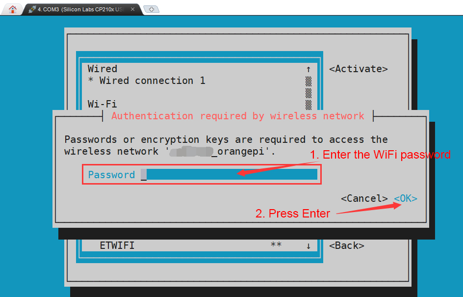
After the WIFI connection is successful, a "*" will be displayed in front of the connected WIFI name.
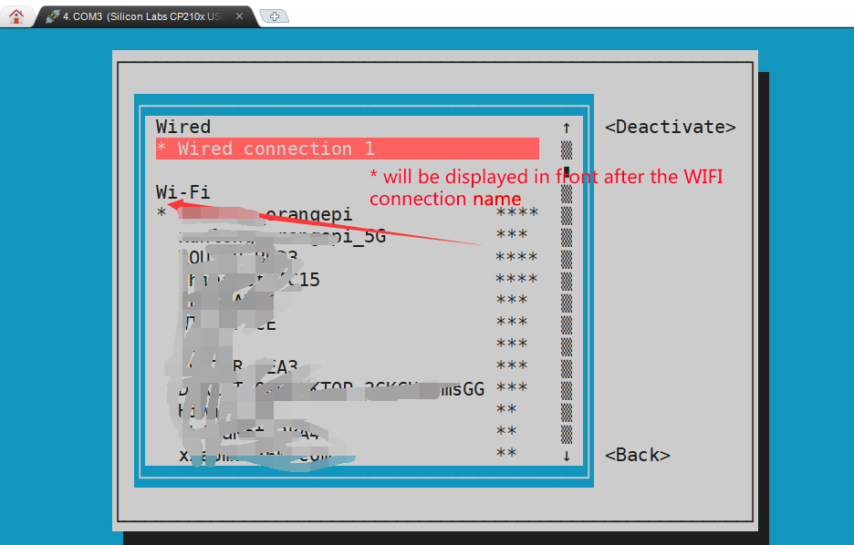
You can check the IP address of the wifi through the ip addr show wlan0 command
orangepi@orangepi:~$ ip addr show wlan0
11: wlan0: <BROADCAST,MULTICAST,UP,LOWER_UP> mtu 1500 qdisc pfifo_fast state UP group default qlen 1000
link/ether 24:8c:d3:aa:76:bb brd ff:ff:ff:ff:ff:ff
inet 192.168.1.11/24 brd 192.168.1.255 scope global dynamic noprefixroute wlan0
valid_lft 259069sec preferred_lft 259069sec
inet6 240e:3b7:3240:c4a0:c401:a445:5002:ccdd/64 scope global dynamic noprefixroute
valid_lft 259071sec preferred_lft 172671sec
inet6 fe80::42f1:6019:a80e:4c31/64 scope link noprefixroute
valid_lft forever preferred_lft forever
Use the ping command to test the connectivity of the wifi network. The ping command can be interrupted by pressing the Ctrl+C shortcut key
orangepi@orangepi:~$ ping www.orangepi.org -I wlan0
PING www.orangepi.org (182.92.236.130) from 192.168.1.49 wlan0: 56(84) bytes of data.
64 bytes from 182.92.236.130 (182.92.236.130): icmp_seq=1 ttl=52 time=43.5 ms
64 bytes from 182.92.236.130 (182.92.236.130): icmp_seq=2 ttl=52 time=41.3 ms
64 bytes from 182.92.236.130 (182.92.236.130): icmp_seq=3 ttl=52 time=44.9 ms
64 bytes from 182.92.236.130 (182.92.236.130): icmp_seq=4 ttl=52 time=45.6 ms
64 bytes from 182.92.236.130 (182.92.236.130): icmp_seq=5 ttl=52 time=48.8 ms
^C
--- www.orangepi.org ping statistics ---
5 packets transmitted, 5 received, 0% packet loss, time 4006ms
rtt min/avg/max/mdev = 41.321/44.864/48.834/2.484 ms


Test method of desktop image
Click the network configuration icon in the upper right corner of the desktop (please do not connect the network cable when testing WIFI)
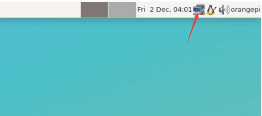
Click More networks in the pop-up drop-down box to see all scanned WIFI hotspots, and then select the WIFI hotspot you want to connect to.

Then enter the password of the WIFI hotspot, and then click Connect to start connecting to WIFI
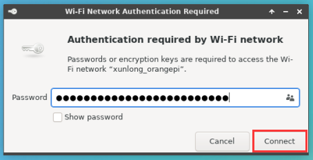
After connecting to WIFI, you can open the browser to check whether you can access the Internet. The entrance of the browser is shown in the figure below
If you can open other web pages after opening the browser, it means the WIFI connection is normal
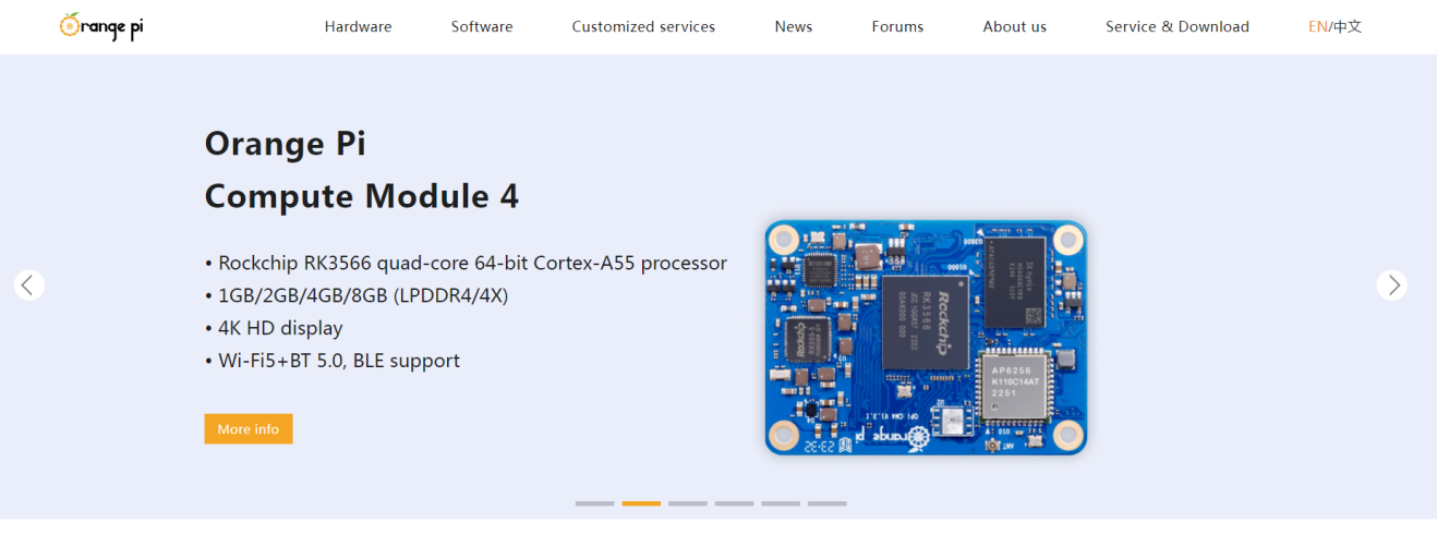


How to set a static IP address
|
Please do not set a static IP address by modifying the /etc/network/interfaces configuration file |
Use the nmtui command to set a static IP address
First run the nmtui command
orangepi@orangepi:~$ nmtui
Then select Edit a connection and press Enter
Then select the network interface for which a static IP address needs to be set. For example, to set the static IP address of the Ethernet interface, select Wired connection 1.
Then select Edit via the Tab key and press the Enter key
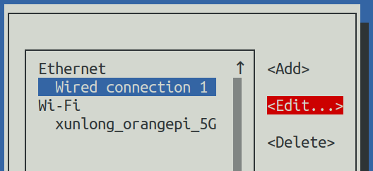
Then use the Tab key to move the cursor to the<Automatic> position shown in the figure below to configure IPv4
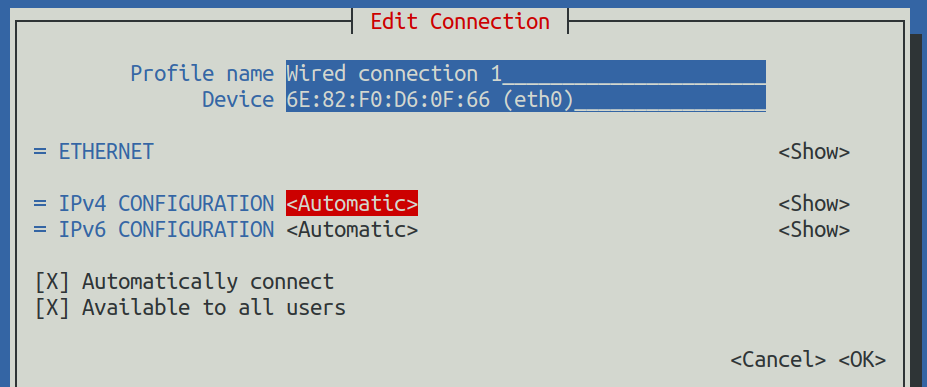
Then press Enter, select Manual through the up and down arrow keys, and then press Enter to confirm.
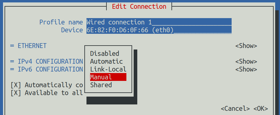
The display after selection is as shown below
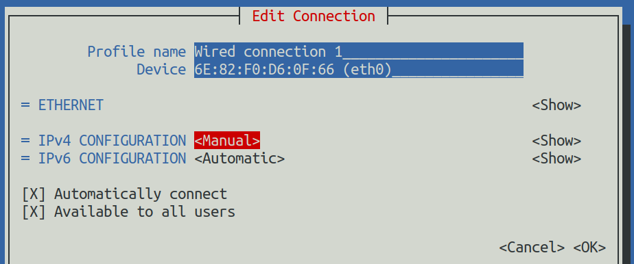
Then move the cursor to <Show> via the Tab key
Then press Enter. After pressing Enter, the following setting interface will pop up.
Then you can set the IP address (Addresses), gateway (Gateway) and DNS server address as shown in the figure below (there are many other setting options, please explore by yourself),Please set it according to your specific needs. The value set in the picture below is just an example.
After setting, move the cursor to <OK> in the lower right corner, and then press Enter to confirm.

Then click <Back> to return to the previous level selection interface
Then select Activate a connection, then move the cursor to <OK>, and finally click Enter
Then select the network interface that needs to be set, such as Wired connection 1, then move the cursor to <Deactivate>, and press Enter to disable Wired connection 1
Then please do not move the cursor, and then press the Enter key to re-enable Wired connection 1, so that the static IP address set earlier will take effect
Then you can exit nmtui through the <Back>and Quit buttons
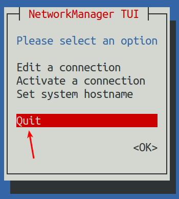
Then through ip addr show eth0, you can see that the IP address of the network port has changed to the static IP address set earlier
orangepi@orangepi:~$ ip addr show eth0
3: eth0: <BROADCAST,MULTICAST,UP,LOWER_UP> mtu 1500 qdisc pfifo_fast state UP group default qlen 1000
link/ether 5e:ac:14:a5:92:b3 brd ff:ff:ff:ff:ff:ff
inet 192.168.1.177/24 brd 192.168.1.255 scope global noprefixroute eth0
valid_lft forever preferred_lft forever
inet6 241e:3b8:3240:c3a0:e269:8305:dc08:135e/64 scope global dynamic noprefixroute
valid_lft 259149sec preferred_lft 172749sec
inet6 fe80::957d:bbbe:4928:3604/64 scope link noprefixroute
valid_lft forever preferred_lft forever
Then you can test the network connectivity to check whether the IP address is configured OK. The ping command can be interrupted by using the Ctrl+C shortcut key.
orangepi@orangepi:~$ ping 192.168.1.47 -I eth0
PING 192.168.1.47 (192.168.1.47) from 192.168.1.188 eth0: 56(84) bytes of data.
64 bytes from 192.168.1.47: icmp_seq=1 ttl=64 time=0.233 ms
64 bytes from 192.168.1.47: icmp_seq=2 ttl=64 time=0.263 ms
64 bytes from 192.168.1.47: icmp_seq=3 ttl=64 time=0.273 ms
64 bytes from 192.168.1.47: icmp_seq=4 ttl=64 time=0.269 ms
64 bytes from 192.168.1.47: icmp_seq=5 ttl=64 time=0.275 ms
^C
--- 192.168.1.47 ping statistics ---
5 packets transmitted, 5 received, 0% packet loss, time 4042ms
rtt min/avg/max/mdev = 0.233/0.262/0.275/0.015 ms


Use the nmcli command to set a static IP address
If you want to set the static IP address of the network port, please insert the network cable into the development board first. If you need to set the static IP address of WIFI, please connect the WIFI first, and then start to set the static IP address
Then you can view the name of the network device through the nmcli con show command, as shown below
orangepi is the name of the WIFI network interface (the name is not necessarily the same)
Wired connection 1 is the name of the Ethernet interface
orangepi@orangepi:~$ nmcli con show
NAMEUUID TYPE DEVICE
orangepicfc4f922-ae48-46f1-84e1-2f19e9ec5e2awifi wlan0
Wired connection 19db058b7-7701-37b8-9411-efc2ae8bfa30ethernet eth0
Then enter the following command,
"Wired connection 1" It means to set the static IP address of the Ethernet port. If you need to set the static IP address of WIFI, please modify it to the corresponding name of the WIFI network interface (you can get it through the nmcli con show)
ipv4.addresses Behind is the static IP address to be set, which can be modified to the value you want to set.
ipv4.gateway Indicates the address of the gateway
orangepi@orangepi:~$ nmcli con mod "Wired connection 1" \
ipv4.addresses "192.168.1.110" \
ipv4.gateway "192.168.1.1" \
ipv4.dns "8.8.8.8" \
ipv4.method "manual"
Then restart the Linux system
orangepi@orangepi:~$ sudo reboot
Then re-enter the Linux system and use the ip addr show eth0 command to see that the IP address has been set to the desired value
orangepi@orangepi:~$ ip addr show eth0
3: eth0: <BROADCAST,MULTICAST,UP,LOWER_UP> mtu 1500 qdisc pfifo_fast state UP group default qlen 1000
link/ether 5e:ae:14:a5:91:b3 brd ff:ff:ff:ff:ff:ff
inet 192.168.1.110/32 brd 192.168.1.110 scope global noprefixroute eth0
valid_lft forever preferred_lft forever
inet6 240e:3b7:3240:c3a0:97de:1d01:b290:fe3a/64 scope global dynamic noprefixroute
valid_lft 259183sec preferred_lft 172783sec
inet6 fe80::3312:861a:a589:d3c/64 scope link noprefixroute
valid_lft forever preferred_lft forever
SSH remote login development board
|
Linux systems enable ssh remote login by default and allow root users to log in to the system. Before ssh login, you first need to ensure that the Ethernet or wifi network is connected, and then use the ip addr command or obtain the IP address of the development board by checking the router. |
SSH remote login development board under Ubuntu
- Obtain the IP address of the development board
- Then you can remotely log in to the Linux system through the ssh command
test@test:~$ ssh root@192.168.1.xxx (Need to be replaced with the IP address of the development board)
root@192.168.1.xx's password: (Enter the password here, the default password is orangepi)
Note that when entering the password, the specific content of the entered password will not be displayed on the screen, please do not think that there is any fault, just press Enter after inputting.
If you are prompted to refuse the connection, as long as you are using the image provided by Orange Pi, please do not suspect that the password orangepi is wrong, but find other reasons
After successfully logging into the system, the display is as shown below
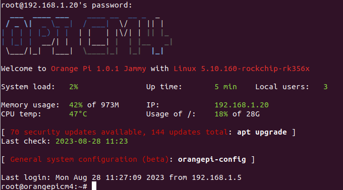
If ssh fails to log in to the Linux system normally, first check whether the IP address of the development board can be pinged. If there is no problem with the ping, you can log in to the Linux system through the serial port or HDMI display, and then enter the following command on the development board and try again. Is it possible to connect:
root@orangepi:~# reset_ssh.sh
If it still doesn't work, please try again by resetting the system.

SSH remote login development board under Windows
First obtain the IP address of the development board
Under Windows, you can use MobaXterm to remotely log in to the development board, first create a new ssh session
Open Session
Then select SSH in Session Setting
Then enter the IP address of the development board in the Remote host
Then enter the username root or orangepi of the Linux system in Specify username
Finally click OK
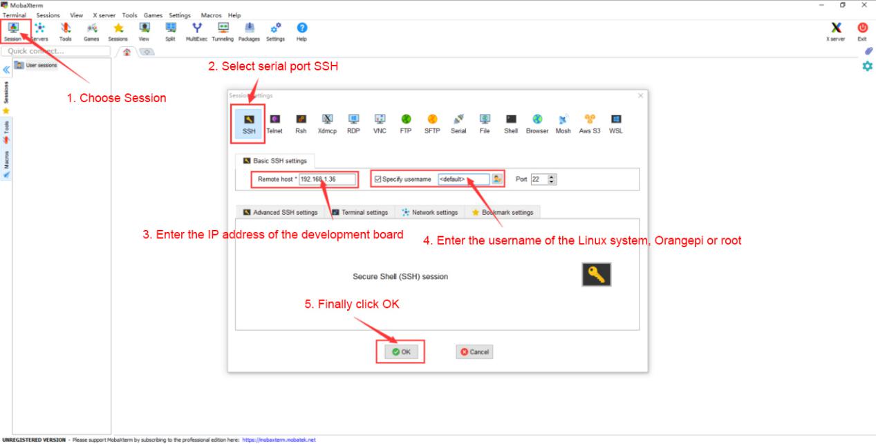
Then you will be prompted to enter a password. The default passwords for root and orangepi users are orangepi
Note that when entering a password, the specific content of the entered password will not be displayed on the screen. Please do not think that there is something wrong. Just press Enter after entering it.
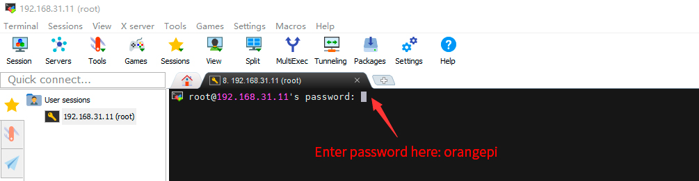


- After successfully logging into the system, the display is as shown below

Method of uploading files to the development board Linux system
How to upload files from Ubuntu PC to development board Linux system
How to upload files using scp command
Use the scp command to upload files from the Ubuntu PC to the Linux system of the development board. The specific commands are as follows
file_path:Need to be replaced with the path of the file to be uploaded
orangepi:This is the username of the Linux system of the development board. It can also be replaced with another one, such as root.
192.168.xx.xx: It is the IP address of the development board, please modify it according to the actual situation
/home/orangepi: The path in the Linux system of the development board can also be modified to other paths
test@test:~$ scp file_path orangepi@192.168.xx.xx:/home/orangepi/
If you want to upload a folder, you need to add the -r parameter
test@test:~$ scp -r dir_path orangepi@192.168.xx.xx:/home/orangepi/
There are more usages of scp, please use the following command to view the man manual
|
test@test:~$ man scp |
How to upload files using filezilla
First install filezilla in Ubuntu PC
test@test:~$ sudo apt install -y filezilla
Then use the following command to open filezilla
test@test:~$ filezilla
The interface after opening filezilla is as shown below. At this time, the remote site on the right is empty.
The method of connecting the development board is as shown in the figure below


Then choose to save the password, and then click OK
Then select Always trust this host and click OK


- After the connection is successful, you can see the directory structure of the development board's Linux file system on the right side of the filezilla software.

- Then select the path to be uploaded to the development board on the right side of the filezilla software, select the file to be uploaded in Ubuntu PC on the left side of the filezilla software, right-click the mouse, and click the upload option to start uploading the file to the development board.

After the upload is complete, you can go to the corresponding path in the Linux system of the development board to view the uploaded files
The method of uploading a folder is the same as the method of uploading a file, so I won't go into details here.
The method of uploading files to the Linux system of the development board in Windows PC
How to upload files using filezilla
- First download the installation file of the Windows version of the filezilla software. The download link is as follows


The downloaded installation package is as shown below, then double-click to install it directly
FileZilla_Server_1.5.1_win64-setup.exe
During the installation process, please select Decline on the following installation interface, and then select <Next>

- The interface after opening filezilla is as shown below. At this time, the remote site on the right is empty.

- The method of connecting the development board is shown in the figure below:
- Then choose to save the password, and then click OK

- Then select Always trust this host and click OK

- After the connection is successful, you can see the directory structure of the development board's Linux file system on the right side of the filezilla software.

- Then select the path to be uploaded to the development board on the right side of the filezilla software, select the file to be uploaded on the Windows PC on the left side of the filezilla software, right-click the mouse, and then click the upload option to start uploading the file to the development board.

After the upload is complete, you can go to the corresponding path in the Linux system of the development board to view the uploaded files
The method of uploading a folder is the same as the method of uploading a file, so I won't go into details here.
HDMI test
HDMI display test
Use Micro HDMI to HDMI cable to connect the Orange Pi development board and HDMI display

After starting the Linux system, if there is image output on the HDMI display, it means that the Micro HDMI interface is working normally.

|
Note that although many laptops have HDMI interfaces, the HDMI interface of the laptop generally only has the output function and does not have the HDMI in function, which means that the HDMI output of other devices cannot be displayed on the laptop screen. When you want to connect the Micro HDMI of the development board to the HDMI port of the laptop, please make sure that your laptop supports the function HDMI in |
|
When HDMI does not display, please first check whether the Micro HDMI cable is plugged in tightly. After confirming that the wiring is OK, you can try a different screen to see if there is a display. |
HDMI resolution setting method
First open Display in Settings

Then you can see the current resolution of the system
Click the drop-down box of Resolution to see all resolutions currently supported by the display
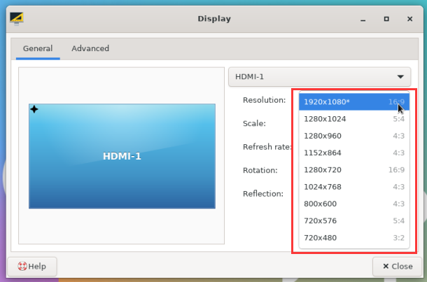
Then select the resolution you want to set and click Apply
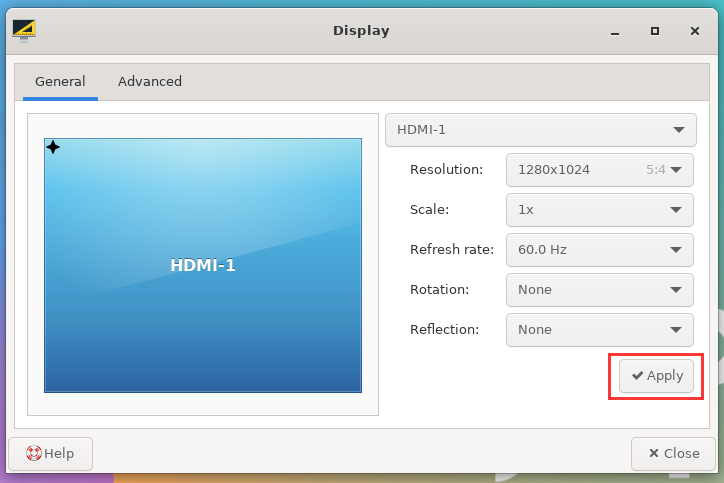
After the new resolution is set, select Keep the configuration
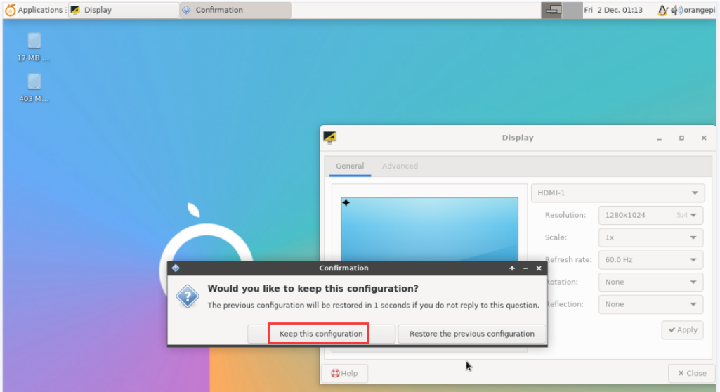


How to use Bluetooth
Test method for desktop image
Click the Bluetooth icon in the upper right corner of the desktop
Then select the adapter
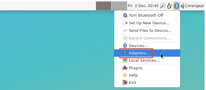
If prompted with the following interface, please select Yes.
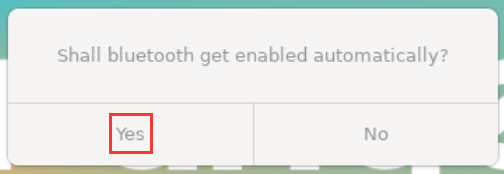
Then set the Visibility Setting to Always visible in the Bluetooth adapter setting interface, and then close it
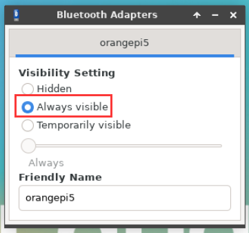
Then open the configuration interface of the Bluetooth device
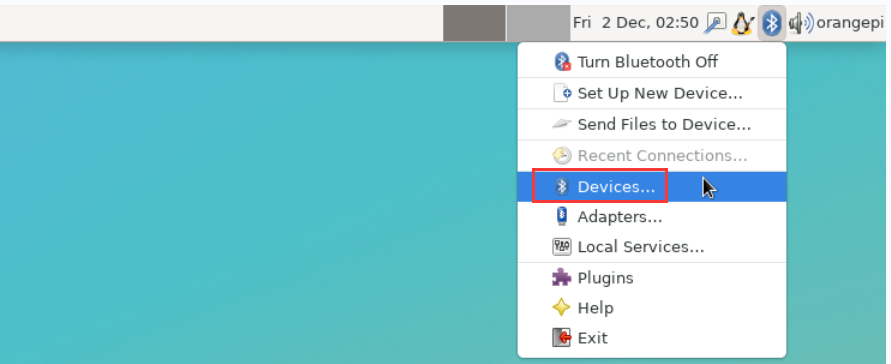
Click Search to start scanning for surrounding Bluetooth devices
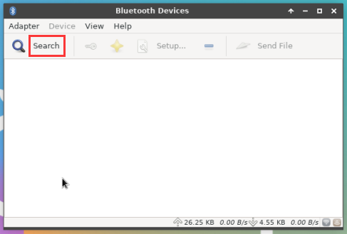
Then select the Bluetooth device you want to connect to, and then click the right mouse button to pop up the operation interface for this Bluetooth device, select Pair to start pairing, and the demonstration here is to pair with an Android phone
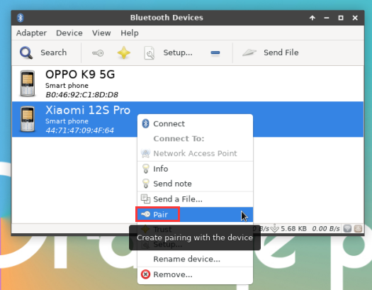
When pairing, a pairing confirmation box will pop up in the upper right corner of the desktop. Just select Confirm to confirm. At this time, you also need to confirm on the mobile phone.
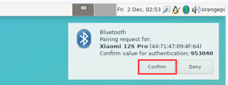
After pairing with the mobile phone, you can select the paired Bluetooth device, then right click and select Send a File to start sending a picture to the mobile phone
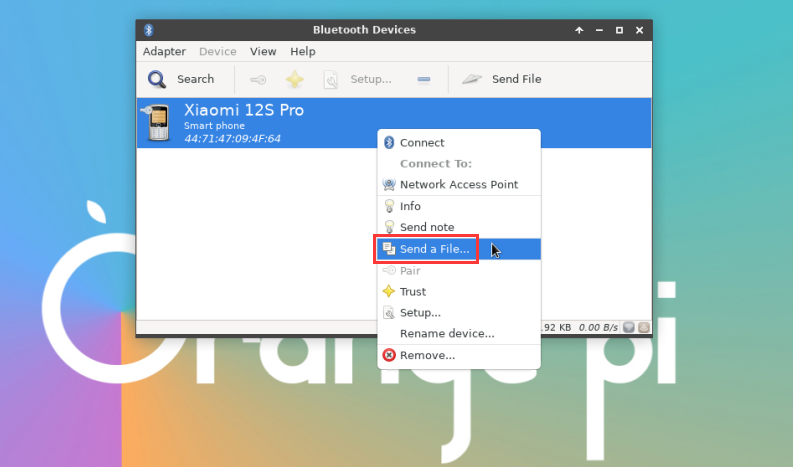
The interface for sending pictures is as follows


USB interface test
|
The USB interface can be connected to a USB hub to expand the number of USB interfaces. |
Connect USB mouse or keyboard to test
- Insert the USB interface keyboard into the USB interface of the Orange Pi development board
- Connect the Orange Pi development board to the HDMI display
- If the mouse or keyboard can operate normally, it means that the USB interface is working normally (the mouse can only be used in the desktop version of the system)
Connect USB storage device to test
- First insert the U disk or USB mobile hard disk into the USB interface of the Orange Pi development board
- Execute the following command, if you can see the output of sdX, it means that the U disk is recognized successfully
orangepi@orangepi:~$ cat /proc/partitions | grep "sd*"
major minor #blocksname
8030044160 sda
8130043119 sda1
- Use the mount command to mount the U disk to /mnt, and then you can view the files in the U disk
|
orangepi@orangepi:~$ sudo mount /dev/sda1 /mnt/ orangepi@orangepi:~$ ls /mnt/ test.txt |
- After mounting, you can check the capacity usage and mount point of the U disk through the df -h command.
|
orangepi@orangepi:~$ df -h | grep "sd" /dev/sda1 29G 208K 29G 1% /mnt |
USB wireless network card test
The usable USB wireless network cards that have been tested so far are as follows. Please test other types of USB wireless network cards by yourself. If they cannot be used, you need to transplant the corresponding USB wireless network card driver.
| serial number | model | |
| 1 |
RTL8723BU support 2.4G WIFI+BT4.0 |

|
| 2 |
RTL8811 support 2.4G +5G WIFI |

|
RTL8723BU test
First insert the RTL8723BU wireless network card module into the USB interface of the development board
Then the Linux system will automatically load the RTL8723BU bluetooth and WIFI-related kernel modules, through the lsmod command, you can see that the following kernel modules have been automatically loaded
orangepi@orangepi:~$ lsmod
Module Size Used by
rfcomm 5734416
rtl8xxxu 1064960
rtk_btusb 614400
Through the dmesg command, you can see the loading information of the RTL8723BU module
orangepi@orangepi:~$ dmesg
......
[ 83.438901] usb 2-1: new high-speed USB device number 2 using ehci-platform
[ 83.588375] usb 2-1: New USB device found, idVendor=0bda, idProduct=b720, bcdDevice= 2.00
[ 83.588403] usb 2-1: New USB device strings: Mfr=1, Product=2, SerialNumber=3
[ 83.588422] usb 2-1: Product: 802.11n WLAN Adapter
[ 83.588443] usb 2-1: Manufacturer: Realtek
[ 83.588460] usb 2-1: SerialNumber: 00e04c000001
[ 83.601974] Bluetooth: hci0: RTL: examining hci_ver=06 hci_rev=000b lmp_ver=06 lmp_subver=8723
[ 83.603894] Bluetooth: hci0: RTL: rom_version status=0 version=1
[ 83.603920] Bluetooth: hci0: RTL: loading rtl_bt/rtl8723b_fw.bin
[ 83.610108] Bluetooth: hci0: RTL: loading rtl_bt/rtl8723b_config.bin
[ 83.611274] Bluetooth: hci0: RTL: cfg_sz 68, total sz 22564
[ 83.658494] rtk_btusb: Realtek Bluetooth USB driver ver 3.1.6d45ddf.20220519-142432
[ 83.658651] usbcore: registered new interface driver rtk_btusb
[ 83.667124] usb 2-1: This Realtek USB WiFi dongle (0x0bda:0xb720) is untested!
[ 83.667137] usb 2-1: Please report results to Jes.Sorensen@gmail.com
[ 83.890140] usb 2-1: Vendor: Realtek
[ 83.890153] usb 2-1: Product: 802.11n WLAN Adapter
[ 83.890159] usb 2-1: rtl8723bu_parse_efuse: dumping efuse (0x200 bytes):
......
[ 83.890412] usb 2-1: RTL8723BU rev E (SMIC) 1T1R, TX queues 3, WiFi=1, BT=1, GPS=0, HI PA=0
[ 83.890417] usb 2-1: RTL8723BU MAC: 00:13:ef:f4:58:ae
[ 83.890421] usb 2-1: rtl8xxxu: Loading firmware rtlwifi/rtl8723bu_nic.bin
[ 83.895289] usb 2-1: Firmware revision 35.0 (signature 0x5301)
[ 84.050893] Bluetooth: hci0: RTL: fw version 0x0e2f9f73
[ 84.266905] Bluetooth: RFCOMM TTY layer initialized
[ 84.266949] Bluetooth: RFCOMM socket layer initialized
[ 84.266999] Bluetooth: RFCOMM ver 1.11
[ 84.884270] usbcore: registered new interface driver rtl8xxxu
[ 84.912046] rtl8xxxu 2-1:1.2 wlx0013eff458ae: renamed from wlan0
Then you can see the device node of RTL8723BU WIFI through the sudo ifconfig command. For the connection and test method of WIFI, please refer to the section of WIFI connection test, which will not be repeated here
orangepi@orangepi:~$ sudo ifconfig wlx0013eff458ae
wlx0013eff458ae: flags=4099<UP,BROADCAST,MULTICAST> mtu 1500
ether 00:13:ef:f4:58:ae txqueuelen 1000 (Ethernet)
RX packets 0 bytes 0 (0.0 B)
RX errors 0 dropped 0 overruns 0 frame 0
TX packets 0 bytes 0 (0.0 B)
TX errors 0 dropped 0 overruns 0 carrier 0 collisions 0
Then you can see the USB Bluetooth device through the hciconfig command
orangepi@orangepi:~$ sudo apt update && sudo apt install bluez
orangepi@orangepi:~$ hciconfig
hci0: Type: Primary Bus: USB
BD Address: 00:13:EF:F4:58:AE ACL MTU: 820:8 SCO MTU: 255:16
DOWN
RX bytes:1252 acl:0 sco:0 events:125 errors:0
TX bytes:23307 acl:0 sco:0 commands:125 errors:0
You can also see the Bluetooth icon on the desktop. Bluetooth is not turned on at this time, so a red x will be displayed
Click Turn Bluetooth On to turn on Bluetooth
The display after turning on Bluetooth is as follows
For the Bluetooth test method, please refer to the section on Bluetooth usage and will not be repeated here.


RTL8811 test
First insert the RTL8811 wireless network card module into the USB interface of the development board
Then the Linux system will automatically load the kernel module related to RTL8811 WIFI. Through the lsmod command, you can see that the following kernel module has been automatically loaded.
orangepi@orangepi:~$ lsmod
Module Size Used by
8821cu 1839104 0
You can see the loading information of the RTL8811 module through the dmesg command
orangepi@orangepi:~$ dmesg
[ 118.618194] usb 2-1: new high-speed USB device number 2 using ehci-platform
[ 118.767152] usb 2-1: New USB device found, idVendor=0bda, idProduct=c811, bcdDevice= 2.00
[ 118.767181] usb 2-1: New USB device strings: Mfr=1, Product=2, SerialNumber=3
[ 118.767199] usb 2-1: Product: 802.11ac NIC
[ 118.767219] usb 2-1: Manufacturer: Realtek
[ 118.767235] usb 2-1: SerialNumber: 123456
[ 119.500530] usbcore: registered new interface driver rtl8821cu
[ 119.525498] rtl8821cu 2-1:1.0 wlx1cbfced9d260: renamed from wlan0
Then, you can see the WIFI device node through the sudo ifconfig command. For the WIFI connection and test method, please refer to the WIFI connection test section, which will not be repeated here
orangepi@orangepi:~$ sudo ifconfig wlx1cbfced9d260
wlx1cbfced9d260: flags=4099<UP,BROADCAST,MULTICAST> mtu 1500
ether 1c:bf:ce:d9:d2:60 txqueuelen 1000 (Ethernet)
RX packets 0 bytes 0 (0.0 B)
RX errors 0 dropped 0 overruns 0 frame 0
TX packets 0 bytes 0 (0.0 B)
TX errors 0 dropped 0 overruns 0 carrier 0 collisions 0
USB camera test
First, you need to prepare a USB camera as shown in the picture below or similar that supports UVC protocol, and then insert the USB camera into the USB interface of the Orange Pi development board
Through the v4l2-ctl command, you can see that the device node information of the USB camera is /dev/video0
orangepi@orangepi:~$ v4l2-ctl --list-devices
Q8 HD Webcam: Q8 HD Webcam (usb-fc880000.usb-1):
/dev/video0
/dev/video1
/dev/media0
Note that l in v4l2 is a lowercase letter l, not the number 1
In addition, the serial number of the video is not necessarily video0, please refer to what you actually see.
In the desktop system, you can use Cheese to directly open the USB camera. The method of opening Cheese is as shown in the figure below:
The interface after Cheese turns on the USB camera is as shown below:
How to use fswebcam to test USB camera
Install fswebcam
orangepi@orangepi:~$ sudo apt update
orangepi@orangepi:~$ sudo apt-get install -y fswebcam
After installing fswebcam, you can use the following command to take pictures
a) -d option is used to specify the device node of the USB camera
b) --no-banner Used to remove watermarks from photos
c) -r option to specify the resolution of the photo
d) -S Option to set the number of previous frames to skip
e) ./image.jpg Used to set the name and path of the generated photo
orangepi@orangepi:~$ sudo fswebcam -d /dev/video0 \
--no-banner -r 1280x720 -S 5 ./image.jpg
In the server version of the Linux system, you can use the scp command to transfer the taken pictures to the Ubuntu PC for mirror viewing after taking pictures
orangepi@orangepi:~$ scp image.jpg test@192.168.1.55:/home/test (Modify the IP address and path according to the actual situation)
In the desktop version of the Linux system, you can directly view the captured pictures through the HDMI display


Audio test
Testing audio methods on desktop systems
First open the file manager
Then find the following file (if there is no such audio file in the system, you can upload an audio file to the system yourself)
Then select the audio.wav file, right-click and select open with vlc to start playing.
How to switch between different audio devices such as HDMI playback and headphone playback
First open the volume control interface

When playing audio, the audio device options that can be used by the playback software will be displayed in Playback, as shown in the figure below. Here you can set which audio device needs to be played
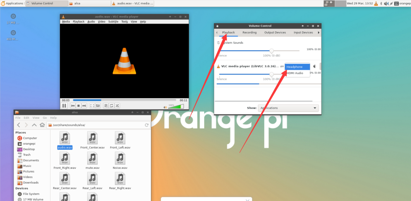


How to use commands to play audio
Headphone interface audio playback test
First insert the headphones into the headphone jack of the development board
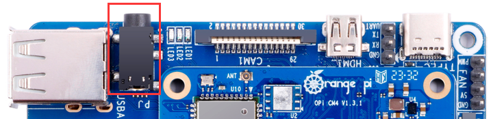
Then you can use the aplay -l command to check the sound card devices supported by the Linux system. From the output below, we can see that card 0 is the sound card device of rk809, which is the sound card device of the headset.
orangepi@orangepi:~$ aplay -l
**** List of PLAYBACK Hardware Devices ****
card 0: rockchiprk809 [rockchip-rk809], device 0: dailink-multicodecs rk817-hifi-0 [dailink-multicodecs rk817-hifi-0]
Subdevices: 0/1
Subdevice #0: subdevice #0
card 1: rockchiphdmi [rockchip,hdmi], device 0: fe400000.i2s-i2s-hifi i2s-hifi-0 [fe400000.i2s-i2s-hifi i2s-hifi-0]
Subdevices: 0/1
Subdevice #0: subdevice #0
Subdevice #0: subdevice #0
Then use the aplay command to play the audio file that comes with the system. If the headset can hear the sound, it means that the hardware can be used normally.
orangepi@orangepi:~$ aplay -D hw:0,0 /usr/share/sounds/alsa/audio.wav
Playing WAVE 'audio.wav' : Signed 16 bit Little Endian, Rate 44100 Hz, Stereo

HDMI audio playback test
First use a Micro HDMI to HDMI cable to connect the Orange Pi development board to the TV (other HDMI displays need to ensure that they can play audio)
Then check the serial number of the HDMI sound card. From the output below, you can know that the HDMI sound card is card 1
orangepi@orangepi:~$ aplay -l
**** List of PLAYBACK Hardware Devices ****
card 0: rockchiprk809 [rockchip-rk809], device 0: dailink-multicodecs rk817-hifi-0 [dailink-multicodecs rk817-hifi-0]
Subdevices: 0/1
Subdevice #0: subdevice #0
card 1: rockchiphdmi [rockchip,hdmi], device 0: fe400000.i2s-i2s-hifi i2s-hifi-0 [fe400000.i2s-i2s-hifi i2s-hifi-0]
Subdevices: 0/1
Subdevice #0: subdevice #0
Subdevice #0: subdevice #0
Then use the aplay command to play the audio file that comes with the system. If the sound can be heard on the HDMI display or TV, it means that the hardware can be used normally.
orangepi@orangepi:~$ aplay -D hw:1,0 /usr/share/sounds/alsa/audio.wav
How to test recording using commands
The Orange Pi CM4 development board does not have an onboard MIC, and audio can only be recorded through headphones with a MIC function. After inserting the headset with MIC function into the development board, run the following command to record an audio period through the headset.
orangepi@orangepi:~$ amixer -c 0 cset name='Capture MIC Path' 'Main Mic'
orangepi@orangepi:~$ arecord -D hw:0,0 -d 5 -f cd -t wav /tmp/test.wav
Temperature sensor
- The command to view the system temperature sensor is:
orangepi@orangepi:~$ sensors
soc_thermal-virtual-0
Adapter: Virtual device
temp1: +41.9°C (crit = +115.0°C)
gpu_thermal-virtual-0
Adapter: Virtual device
temp1: +43.8°C
The command to view the current temperature of the nvme ssd solid state drive is:
orangepi@orangepi:~$ sudo smartctl -a /dev/nvme0 | grep "Temperature:"
Temperature: 40 Celsius
40 Pin interface pin description
Please refer to the picture below for the order of the 40-pin interface pins of the Orange Pi CM4 development board
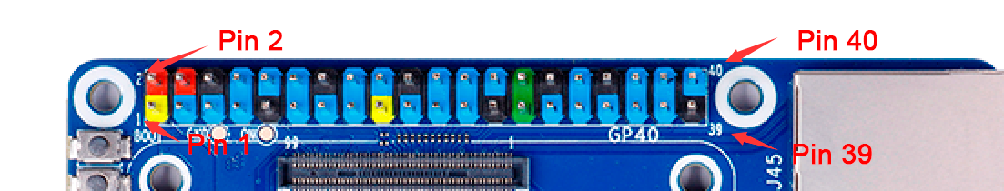
The functions of the 40-pin interface pins of the Orange Pi CM4 development board are as shown in the table below
The following is the complete pin diagram of 40pin
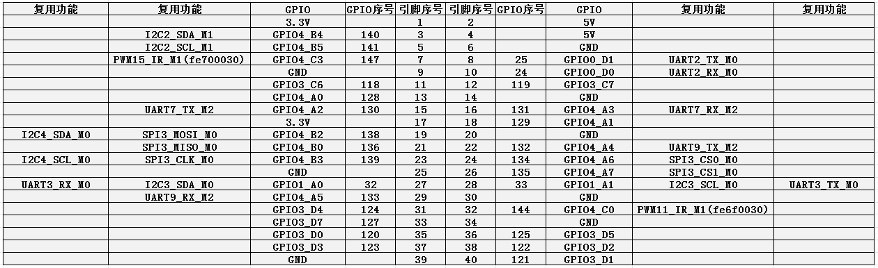
The table below is the picture of the left half of the complete table above, so you can see it clearly
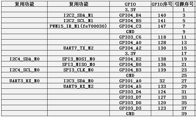
The table below is the picture of the right half of the complete table above, so you can see it clearly
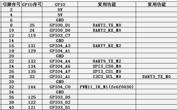
There are a total of 28 GPIO ports in the 40pin interface, and the voltage of all GPIO ports is 3.3v


How to install wiringOP
|
Note that wiringOP is already pre-installed in the Linux image released by Orange Pi. Unless the wiringOP code is updated, there is no need to re-download, compile and install it, just use it directly.
orangepi-build/external/cache/debs/arm64/wiringpi_x.xx.deb
 WiringOP currently mainly adapts to the functions of setting GPIO port input and output, setting GPIO port output high and low levels, and setting pull-up and pull-down resistors. Functions such as hardware PWM cannot be used. |
Download the code of wiringOP
orangepi@orangepi:~$ sudo apt update
orangepi@orangepi:~$ sudo apt install -y git
orangepi@orangepi:~$ git clone https://github.com/orangepi-xunlong/wiringOP.git -b next
Note that Orange Pi CM4 needs to download the code of wiringOP next branch. Please don’t miss the -b next parameter.
If you have problems downloading the code from GitHub, you can directly use the wiringOP source code that comes with the Linux image, and the storage location is: /usr/src/wiringOP.
Compile and install wiringOP
orangepi@orangepi:~$ cd wiringOP
orangepi@orangepi:~/wiringOP$ sudo ./build clean
orangepi@orangepi:~/wiringOP$ sudo ./build
Test the output of the gpio readall command as follows
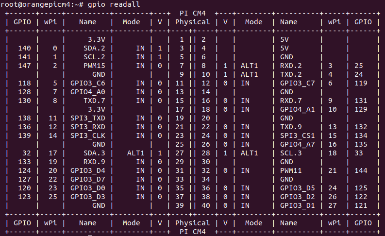
40pin interface GPIO, I2C, UART, SPI and PWM test
|
Note, if you need to set overlays to open multiple configurations at the same time, please use spaces to separate them and write them on one line as follows.
overlays=spi3-m0-cs0-spidev i2c2-m1 i2c3-m0 uart7-m2 uart9-m2 pwm11-m1 |
40pin GPIO port test
|
The Linux system released by Orange Pi has a pre-installed blink_all_gpio program, which will set all 28 GPIO ports in the 40pin to switch between high and low levels continuously.
orangepi@orangepicm4:~$ sudo blink_all_gpio # Remember to add sudo permission [sudo] password for orangepi: # A password is required here |
- There are a total of 28 GPIO ports in the 40pins of the development board that can be used. The following uses pin 7—the corresponding GPIO is GPIO4_C3——the corresponding wPi serial number is 2—as an example to demonstrate how to set the high and low levels of the GPIO port

- First set the GPIO port to output mode, where the third parameter needs to input the serial number of wPi corresponding to the pin
|
root@orangepi:~/wiringOP# gpio mode 2 out |
- Then set the GPIO port to output low level. After setting, you can use a multimeter to measure the voltage value of the pin. If it is 0v, it means that the low level is set successfully.
|
root@orangepi:~/wiringOP# gpio write 2 0 |
Use gpio readall to see that the value (V) of pin 7 has changed to 0

- Then set the GPIO port to output a high level. After setting, you can use a multimeter to measure the voltage value of the pin. If it is 3.3v, it means that the high level is set successfully
|
root@orangepi:~/wiringOP# gpio write 2 1 |
Use gpio readall to see that the value (V) of pin 7 has changed to 1

- The setting method of other pins is similar, just modify the serial number of wPi to the corresponding serial number of the pin
How to set the pull-up and pull-down resistance of 40pin GPIO port
|
Note that the 4 GPIO pins below the Orange Pi CM4 have an external 3.3V pull-up, so setting the pull-down is invalid, and the other pins can normally set the pull-up and pull-down resistor function  |
- The following takes pin 11—the corresponding GPIO is GPIO3_C6—the corresponding wPi serial number is 5—as an example to demonstrate how to set the pull-up and pull-down resistance of the GPIO port

- First, you need to set the GPIO port to the input mode, and the third parameter needs to be the serial number of the wPi corresponding to the input pin
|
root@orangepi:~/wiringOP# gpio mode 5 in |
- After setting to input mode, execute the following command to set the GPIO port to pull-up mode
|
root@orangepi:~/wiringOP# gpio mode 5 up |
- Then enter the following command to read the level of the GPIO port, if the level is 1, it means that the pull-up mode is set successfully
|
root@orangepi:~/wiringOP# gpio read 5 1 |
- Then execute the following command to set the GPIO port to pull-down mode
|
root@orangepi:~/wiringOP# gpio mode 5 down |
- Then enter the following command to read the level of the GPIO port, if the level is 0, the pull-down mode is set successfully
|
root@orangepi:~/wiringOP# gpio read 5 0 |
40pin SPI test
- According to the schematic diagram of the 40pin interface, the spi available for Orange Pi CM4 is spi3

In the linux system, the SPI in the 40 pin is closed by default, and it needs to be opened manually to use it. The detailed steps are as follows:
- First run orangepi-config, common users remember to add sudo permission
orangepi@orangepi:~$ sudo orangepi-config
- Then select System
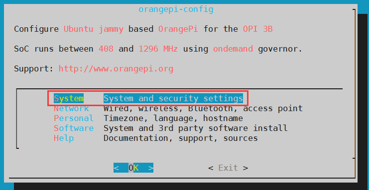
- Then select Hardware
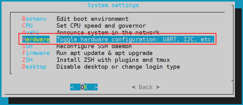
- Then use the arrow keys on the keyboard to navigate to the position shown in the figure below, and then use the space to select the SPI configuration you want to open
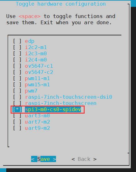
- Then select <Save>Save
- Then select<Back>
- Then select<Reboot> Restart the system for the configuration to take effect
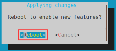


- After restarting, enter the system to check whether there is a spidev3.0 device node in the Linux system. If it exists, it means that SPI3 has been set up and can be used directly
|
orangepi@orangepi:~$ ls /dev/spidev3.0 /dev/spidev3.0 |
- Do not short-circuit the mosi and miso pins of SPI3 first, and the output result of running spidev_test is as follows, you can see that the data of TX and RX are inconsistent
|
orangepi@orangepi:~$ sudo spidev_test -v -D /dev/spidev3.0 spi mode: 0x0 bits per word: 8 max speed: 500000 Hz (500 KHz) TX | FF FF FF FF FF FF 40 00 00 00 00 95 FF FF FF FF FF FF FF FF FF FF FF FF FF FF FF FF FF FF F0 0D | ......@.…▒..................▒. RX | FF FF FF FF FF FF FF FF FF FF FF FF FF FF FF FF FF FF FF FF FF FF FF FF FF FF FF FF FF FF FF FF | ............................…. |
- Then short-circuit the two pins of mosi (pin 19 in the 40pin interface) and miso (pin 21 in the 40pin interface) of SPI3 and run the output of spidev_test as follows, you can see the sending and receiving same data

|
orangepi@orangepi:~$ sudo spidev_test -v -D /dev/spidev3.0 spi mode: 0x0 bits per word: 8 max speed: 500000 Hz (500 KHz) TX | FF FF FF FF FF FF 40 00 00 00 00 95 FF FF FF FF FF FF FF FF FF FF FF FF FF FF FF FF FF FF F0 0D | ......@.…▒..................▒. RX | FF FF FF FF FF FF 40 00 00 00 00 95 FF FF FF FF FF FF FF FF FF FF FF FF FF FF FF FF FF FF F0 0D | ......@.…▒..................▒. |
40pin I2C test
- As can be seen from the table below, the available i2c for Orange Pi CM4 is i2c2, i2c3 and i2c4, a total of three sets of i2c buses

As can be seen from the above table, i2c4_m0 and spi3_m0 are multiplexed pins, and both cannot be opened at the same time. i2c3_m0 and uart3_m0 are also multiplexed pins, and both cannot be opened at the same time
In the linux system, the I2C bus in the 40 pin is closed by default, and it needs to be opened manually to use it. The detailed steps are as follows:
- First run orangepi-config, common users remember to add sudo permission
orangepi@orangepi:~$ sudo orangepi-config
- Then select System
- Then select Hardware
- Then use the arrow keys on the keyboard to navigate to the position shown in the figure below, and then use the space to select the I2C configuration you want to open

- Then select <Save> Save
- Then select <Back>
- Then select<Reboot> Restart the system for the configuration to take effect

- After starting the Linux system, first confirm that there is an i2c device node under /dev
|
orangepi@orangepi:~# ls /dev/i2c-* /dev/i2c-0 /dev/i2c-2 /dev/i2c-3 /dev/i2c-4 /dev/i2c-6 |
- Then connect an i2c device to the i2c pin of the 40pin connector
| i2c2-m1 | i2c3-m0 | i2c4-m0 | |
| Sda Pin | Corresponding to No.3 pin | Corresponding to No.27 pin | Corresponding to No.19 pin |
| Sck Pin | Corresponding to No.5 pin | Corresponding to No.28 pin | Corresponding to No.23 pin |
| Vcc Pin | Corresponding to No.1 pin | Corresponding to No.1 pin | Corresponding to No.1 pin |
| Gnd Pin | Corresponding to No.6 pin | Corresponding to No.6 pin | Corresponding to No.6 pin |
- Then use the i2cdetect -y command, if the address of the connected i2c device can be detected, it means that i2c can be used normally
|
orangepi@orangepi:~$ sudo i2cdetect -y 2 #i2c2 command orangepi@orangepi:~$ sudo i2cdetect -y 3 #i2c3 command orangepi@orangepi:~$ sudo i2cdetect -y 4 #i2c4 command |

40pin UART test
- As can be seen from the table below, the available uarts of Orange Pi CM4 are three sets of uart buses: uart3, uart7 and uart9

As can be seen from the above table, i2c3_m0 and uart3_m0 are multiplexed pins, and both cannot be opened at the same time
In the linux system, the UART in the 40 pins is closed by default, and it needs to be opened manually to use. The detailed steps are as follows:
- First run orangepi-config, common users remember to add sudo permission
orangepi@orangepi:~$ sudo orangepi-config
- Then select System
- Then select Hardware
- Then use the arrow keys on the keyboard to navigate to the position shown in the figure below, and then use the space to select the UART configuration you want to open

- Then select <Save> Save
- Then select <Back>
- Then select <Reboot> Restart the system for the configuration to take effect


- After entering the Linux system, first confirm whether there is a device node corresponding to uart under /dev
|
orangepi@orangepi:~# ls /dev/ttyS* /dev/ttyS1 /dev/ttyS3 /dev/ttyS7 /dev/ttyS9 |
- Then start to test the uart interface, first use the DuPont line to short the rx and tx of the uart interface to be tested
| uart3 | uart7 | uart9 | |
| tx pin | Corresponding to pin 28 | Corresponding to pin 16 | Corresponding to pin 29 |
| rx pin | Corresponding to pin 27 | Corresponding to pin 15 | Corresponding to pin 22 |

Use the gpio serial command to test the loopback function of the serial port as shown below, if you can see the following print, it means the serial port communication is normal
- Test UART3
orangepi@orangepi:~$ sudo gpio serial /dev/ttyS3
[sudo] password for orangepi: # enter password here
Out: 0: -> 0Out: 1: -> 1
Out: 2: -> 2
Out: 3: -> 3
Out: 4: -> 4
Out: 5: -> 5^C
- Test UART7
orangepi@orangepi:~$ sudo gpio serial /dev/ttyS7
[sudo] password for orangepi: #enter password here
Out: 0: -> 0Out: 1: -> 1
Out: 2: -> 2
Out: 3: -> 3
Out: 4: -> 4
Out: 5: -> 5^C
- Test UART9
orangepi@orangepi:~$ sudo gpio serial /dev/ttyS9
[sudo] password for orangepi: # enter password here
Out: 0: -> 0Out: 1: -> 1
Out: 2: -> 2
Out: 3: -> 3
Out: 4: -> 4
Out: 5: -> 5^C
PWM test method
- As can be seen from the table below, Orange Pi CM4 has two channels of pwm available pwm11 and pwm15

In the linux system, the PWM in the 40 pin is turned off by default, and it needs to be turned on manually before it can be used. The detailed steps are as follows:
- First run orangepi-config, common users remember to add sudo permission
orangepi@orangepi:~$ sudo orangepi-config
- Then selectSystem
- Then select Hardware
- Then use the arrow keys on the keyboard to navigate to the position shown in the figure below, and then use the space to select the PWM configuration you want to open

- Then select <Save> Save
- Then select <Back>
- Then select <Reboot> Restart the system for the configuration to take effect

- After opening a pwm, there will be an extra pwmchipX in /sys/class/pwm/ (X is a specific number), for example, after opening pwm11, check the pwmchipX under /sys/class/pwm/ one becomes two
|
orangepi@orangepi:~$ ls /sys/class/pwm/ pwmchip0 pwmchip1 |
- Which of the above pwmchips corresponds to pwm11? Let’s first check the output of the ls /sys/class/pwm/ -l command, as shown below:

- Then it can be known from the table below that the base address of the pwm11 register is fe6f0030, and then look at the output of the ls /sys/class/pwm/ -l command, you can see that pwmchip1 is linked to fe6f0030.pwm, so pwm11 corresponds to pwmchip as pwmchip1

- Then use the following command to make pwm11 output a 50Hz square wave (please switch to the root user first, and then execute the following command)
|
root@orangepi:~# echo 0 > /sys/class/pwm/pwmchip1/export root@orangepi:~# echo 20000000 > /sys/class/pwm/pwmchip1/pwm0/period root@orangepi:~# echo 1000000 > /sys/class/pwm/pwmchip1/pwm0/duty_cycle root@orangepi:~# echo 1 > /sys/class/pwm/pwmchip1/pwm0/enable |

- The test method of pwm11 demonstrated above is similar to other pwm test methods.
How to install and use wiringOP-Python
|
wiringOP-Python is the Python language version of wiringOP, which is used to operate the hardware resources of the development board, such as GPIO, I2C, SPI and UART, in the Python program. In addition, please note that all the following commands are operated under the root user. |
How to install wiringOP-Python
- First install the dependent packages
root@orangepi:~# sudo apt-get update
root@orangepi:~# sudo apt-get -y install git swig python3-dev python3-setuptools
- Then use the following command to download the source code of wiringOP-Python
|
Note that the following git clone--recursive command will automatically download the source code of wiringOP, because wiringOP-Python depends on wiringOP. Please make sure that the download process does not report errors due to network problems. If you have problems downloading the code from GitHub, you can directly use the wiringOP-Python source code that comes with the Linux image, and the storage location is:/usr/src/wiringOP-Python. |
|
root@orangepi:~# git clone --recursive https://github.com/orangepi-xunlong/wiringOP-Python -b next root@orangepi:~# cd wiringOP-Python root@orangepi:~/wiringOP-Python# git submodule update --init --remote |
- Then use the following command to compile wiringOP-Python and install it into the Linux system of the development board
|
root@orangepi:~# cd wiringOP-Python root@orangepi:~/wiringOP-Python# python3 generate-bindings.py > bindings.i root@orangepi:~/wiringOP-Python# sudo python3 setup.py install |
- Then enter the following command, if there is help information output, it means that wiringOP-Python is installed successfully, press the q key to exit the help information interface
- wiringpi
- # This file was automatically generated by SWIG (http://www.swig.org).
- # Version 4.0.2
- #
- # Do not make changes to this file unless you know what you are doing--modify
- # the SWIG interface file instead.
|
root@orangepi:~/wiringOP-Python# python3 -c "import wiringpi; help(wiringpi)" Help on module wiringpi:
|
The steps to test whether wiringOP-Python is successfully installed under the python command line are as follows:
- First use the python3 command to enter the command line mode of python3
root@orangepi:~# python3
- Then import the python module of wiringpi
>>> import wiringpi;
- Finally, enter the following command to view the help information of wiringOP-Python, press the q key to exit the help information interface
- wiringpi
- # This file was automatically generated by SWIG (http://www.swig.org).
- # Version 4.0.2
- #
- # Do not make changes to this file unless you know what you are doing--modify
- # the SWIG interface file instead.
- builtins.object
- GPIO
- I2C
- Serial
- nes
- class GPIO(builtins.object)
- | GPIO(pinmode=0)
- |
>>> help(wiringpi)
Help on module wiringpi:
NAME
DESCRIPTION
CLASSES
>>>
40pin GPIO port test
|
wiringOP-Python is the same as wiringOP, you can also determine which GPIO pin to operate by specifying the wPi number, because there is no command to check the wPi number in wiringOP-Python, so you can only check the board wPi number and physical Correspondence between pins. |
- The following takes pin No. 7—the corresponding GPIO is GPIO4_C3—the corresponding wPi number is 2—as an example to demonstrate how to set the high and low levels of the GPIO port
The steps to test directly with the command are as follows
- First set the GPIO port to output mode, where the first parameter of the pinMode function is the serial number of the wPi corresponding to the pin, and the second parameter is the GPIO mode
root@orangepi:~/wiringOP-Python# python3 -c "import wiringpi; \
from wiringpi import GPIO; wiringpi.wiringPiSetup() ; \
wiringpi.pinMode(2, GPIO.OUTPUT) ; "
- Then set the GPIO port to output low level. After setting, you can use a multimeter to measure the voltage value of the pin. If it is 0v, it means that the low level is set successfully.
root@orangepi:~/wiringOP-Python# python3 -c "import wiringpi; \
from wiringpi import GPIO; wiringpi.wiringPiSetup() ;\
wiringpi.digitalWrite(2, GPIO.LOW)"
- Then set the GPIO port to output a high level. After setting, you can use a multimeter to measure the voltage value of the pin. If it is 3.3v, it means that the high level is set successfully.
root@orangepi:~/wiringOP-Python# python3 -c "import wiringpi; \
from wiringpi import GPIO; wiringpi.wiringPiSetup() ;\
wiringpi.digitalWrite(2, GPIO.HIGH)"
The steps to test in the python3 command line are as follows:
- First use the python3 command to enter the command line mode of python3
root@orangepi:~# python3
- Then import the python module of wiringpi
>>> import wiringpi
>>> from wiringpi import GPIO
- Then set the GPIO port to output mode, where the first parameter of the pinMode function is the serial number of the wPi corresponding to the pin, and the second parameter is the GPIO mode
>>> wiringpi.wiringPiSetup()
0
>>> wiringpi.pinMode(2, GPIO.OUTPUT)
- Then set the GPIO port to output a low level. After setting, you can use a multimeter to measure the voltage value of the pin. If it is 0v, it means that the low level is set successfully.
>>> wiringpi.digitalWrite(2, GPIO.LOW)
- Then set the GPIO port to output a high level. After setting, you can use a multimeter to measure the voltage value of the pin. If it is 3.3v, it means that the high level is set successfully.
>>> wiringpi.digitalWrite(2, GPIO.HIGH)
- The method of setting GPIO high and low levels in the python code by wiringOP-Python can refer to the blink.py test program in the examples below. The blink.py test program will set the voltage of all GPIO ports in the 40 pins of the development board to change continuously.
|
root@orangepi:~/wiringOP-Python# cd examples root@orangepi:~/wiringOP-Python/examples# ls blink.py blink.py root@orangepi:~/wiringOP-Python/examples# python3 blink.py |
40pin SPI test
- According to the schematic diagram of the 40pin interface, the spi available for Orange Pi CM4 is spi3
In the linux system, the SPI in the 40 pin is closed by default, and it needs to be opened manually to use it. The detailed steps are as follows:
- First run orangepi-config, common users remember to add sudo permission
orangepi@orangepi:~$ sudo orangepi-config
- Then select System
- Then select Hardware
- Then use the arrow keys on the keyboard to navigate to the position shown in the figure below, and then use the space to select the SPI configuration you want to open
- Then select <Save>Save
- Then select <Back>
- Then select<Reboot> Restart the system for the configuration to take effect
- First check whether there is a spidev3.0 device node in the Linux system. If it exists, it means that SPI3 has been set up and can be used directly
|
orangepi@orangepi:~$ ls /dev/spidev3.0 /dev/spidev3.0 |
- Then you can use the spidev_test.py program in the examples to test the loopback function of the SPI. The spidev_test.py program needs to specify the following two parameters:
- a. -- channel: Specify the channel number of SPI
- b. -- port: Specify the port number of SPI
- Do not short-circuit the mosi and miso pins of SPI3, the output of running spidev_test.py is as follows, you can see that the data of TX and RX are inconsistent
|
root@orangepi:~/wiringOP-Python# cd examples root@orangepi:~/wiringOP-Python/examples# python3 spidev_test.py \ --channel 3 --port 0 spi mode: 0x0 max speed: 500000 Hz (500 KHz) Opening device /dev/spidev3.0 TX | FF FF FF FF FF FF 40 00 00 00 00 95 FF FF FF FF FF FF FF FF FF FF FF FF FF FF FF FF FF FF F0 0D |......@.......…| RX | FF FF FF FF FF FF FF FF FF FF FF FF FF FF FF FF FF FF FF FF FF FF FF FF FF FF FF FF FF FF FF FF |.............….| |
- Then use the Dupont wire to short-circuit the two pins of txd (pin 19 in the 40pin interface) and rxd (pin 21 in the 40pin interface) of SPI3 and then run the output of spidev_test.py as follows, you can see The data sent and received are the same, indicating that the SPI3 loopback test is normal
|
root@orangepi:~/wiringOP-Python# cd examples root@orangepi:~/wiringOP-Python/examples# python3 spidev_test.py \ --channel 3 --port 0 spi mode: 0x0 max speed: 500000 Hz (500 KHz) Opening device /dev/spidev3.0 TX | FF FF FF FF FF FF 40 00 00 00 00 95 FF FF FF FF FF FF FF FF FF FF FF FF FF FF FF FF FF FF F0 0D |......@.......…| RX | FF FF FF FF FF FF 40 00 00 00 00 95 FF FF FF FF FF FF FF FF FF FF FF FF FF FF FF FF FF FF F0 0D |......@.......…| |
40pin I2C test
- As can be seen from the table below, the available i2c for Orange Pi CM4 is i2c2, i2c3 and i2c4, a total of three sets of i2c buses
As can be seen from the above table, i2c4_m0 and spi3_m0 are multiplexed pins, and both cannot be opened at the same time. i2c3_m0 and uart3_m0 are also multiplexed pins, and both cannot be opened at the same time
In the linux system, the I2C bus in the 40 pin is closed by default, and it needs to be opened manually to use it. The detailed steps are as follows:
- First run orangepi-config, common users remember to add sudo permission
orangepi@orangepi:~$ sudo orangepi-config
- Then select System
- Then select Hardware
- Then use the arrow keys on the keyboard to navigate to the position shown in the figure below, and then use the space to select the I2C configuration you want to open
- Then select <Save> Save
- Then select <Back>
Then select <Reboot> Restart the system for the configuration to take effect
- After starting the Linux system, first confirm that there is an i2c device node under /dev
|
orangepi@orangepi:~# ls /dev/i2c-* /dev/i2c-0 /dev/i2c-2 /dev/i2c-3 /dev/i2c-4 /dev/i2c-6 |
- Then connect an i2c device to the i2c pin of the 40pin connector, here we take the ds1307 RTC module as an example
| i2c2-m1 | i2c3-m0 | i2c4-m0 | |
| Sda pin | Corresponding to pin 3 | Corresponding to pin 27 | Corresponding to pin 19 |
| Sck pin | Corresponding to pin 5 | Corresponding to pin 28 | Corresponding to pin 28 |
| Vcc pin | Corresponding to pin 1 | Corresponding to pin 1 | Corresponding to pin 1 |
| Gnd pin | Corresponding to pin 6 | Corresponding to pin 6 | Corresponding to pin 6 |

- Then use the i2cdetect -y command, if the address of the connected i2c device can be detected, it means that i2c can be used normally
|
orangepi@orangepi:~$ sudo i2cdetect -y 2 #i2c2 command orangepi@orangepi:~$ sudo i2cdetect -y 3 #i2c3 command orangepi@orangepi:~$ sudo i2cdetect -y 4 #i2c4 command |
- Then you can run the ds1307.py test program in the examples to read the RTC time
|
root@orangepi:~/wiringOP-Python# cd examples root@orangepi:~/wiringOP-Python/examples# python3 ds1307.py --device \ "/dev/i2c-4" Thu 2023-01-05 14:57:55 Thu 2023-01-05 14:57:56 Thu 2023-01-05 14:57:57 ^C exit |
40pin UART test
- As can be seen from the table below, the available uarts of Orange Pi CM4 are three sets of uart buses: uart3, uart7 and uart9
As can be seen from the above table, i2c3_m0 and uart3_m0 are multiplexed pins, and both cannot be opened at the same time
In the linux system, the UART in the 40 pins is closed by default, and it needs to be opened manually to use. The detailed steps are as follows:
- First run orangepi-config, common users remember to add sudo permission
orangepi@orangepi:~$ sudo orangepi-config
- Then select System
- Then select Hardware
- Then use the arrow keys on the keyboard to navigate to the position shown in the figure below, and then use the space to select the UART configuration you want to open
- Then select<Save> Save
- Then select <Back>
- Then select<Reboot>Restart the system for the configuration to take effect
- After entering the Linux system, first confirm whether there is a device node corresponding to uart under /dev
|
orangepi@orangepi:~# ls /dev/ttyS* /dev/ttyS1 /dev/ttyS3 /dev/ttyS7 /dev/ttyS9 |
- Then start to test the uart interface, first use the DuPont line to short the rx and tx of the uart interface to be tested
| uart3 | uart7 | uart9 | |
| tx pin | Corresponding to pin 28 | Corresponding to pin 16 | Corresponding to pin 29 |
| rx pin | Corresponding to pin 27 | Corresponding to pin 15 | Corresponding to pin 22 |
Use the serialTest.py program in the examples to test the loopback function of the serial port as shown below. If you can see the following print, it means that the serial port communication is normal
- Test UART3
root@orangepi:~/wiringOP-Python/examples# python3 serialTest.py --device \
"/dev/ttyS3"
Out: 0: -> 0
Out: 1: -> 1
Out: 2: -> 2
Out: 3: -> 3
Out: 4:^C
exit
- Test UART7
root@orangepi:~/wiringOP-Python/examples# python3 serialTest.py --device \
"/dev/ttyS7"
Out: 0: -> 0
Out: 1: -> 1
Out: 2: -> 2
Out: 3: -> 3
Out: 4:^C
exit
- Test UART9
root@orangepi:~/wiringOP-Python/examples# python3 serialTest.py --device \
"/dev/ttyS9"
Out: 0: -> 0
Out: 1: -> 1
Out: 2: -> 2
Out: 3: -> 3
Out: 4:^C
exit
Hardware watchdog test
The watchdog_test program is pre-installed in the Linux system released by Orange Pi, which can be tested directly.
The method to run the watchdog_test program is as follows:
a. The second parameter 10 indicates the counting time of the watchdog. If the dog is not fed within this time, the system will restart
b. We can feed the dog by pressing any key on the keyboard (except ESC). After feeding the dog, the program will print a line of keep alive to indicate that the dog is fed successfully
|
orangepi@orangepi:~$ sudo watchdog_test 10 open success options is 33152,identity is sunxi-wdt put_usr return,if 0,success:0 The old reset time is: 16 return ENOTTY,if -1,success:0 return ENOTTY,if -1,success:0 put_user return,if 0,success:0 put_usr return,if 0,success:0 keep alive keep alive keep alive |
Check the serial number of RK3566 chip
The command to view the serial number of the RK3566 chip is as follows. The serial number of each chip is different, so the serial number can be used to distinguish multiple development boards.
|
orangepi@orangepi:~$ cat_serial.sh Serial : 8fa18eaf489041f0 |
How to install Docker
- The linux image provided by Orange Pi has pre-installed Docker, but the Docker service is not enabled by default
- Use the enable_docker.sh script to enable the docker service, and then you can start using the docker command, and the docker service will be automatically started when the system is started next time
orangepi@orangepi:~$ enable_docker.sh
- Then you can use the following command to test docker, if you can run hello-world, it means that docker can be used normally
|
orangepi@orangepi:~$ docker run hello-world Unable to find image 'hello-world:latest' locally latest: Pulling from library/hello-world 256ab8fe8778: Pull complete Digest: sha256:7f0a9f93b4aa3022c3a4c147a449ef11e0941a1fd0bf4a8e6c9408b2600777c5 Status: Downloaded newer image for hello-world:latest
This message shows that your installation appears to be working correctly. .…. |
How to download and install arm64 version balenaEtcher
The download address of balenaEtcher arm64 version is:
- The download address of the deb installation package is as follows, which needs to be installed before it can be used
- The download address of the AppImage version that does not need to be installed is as follows:
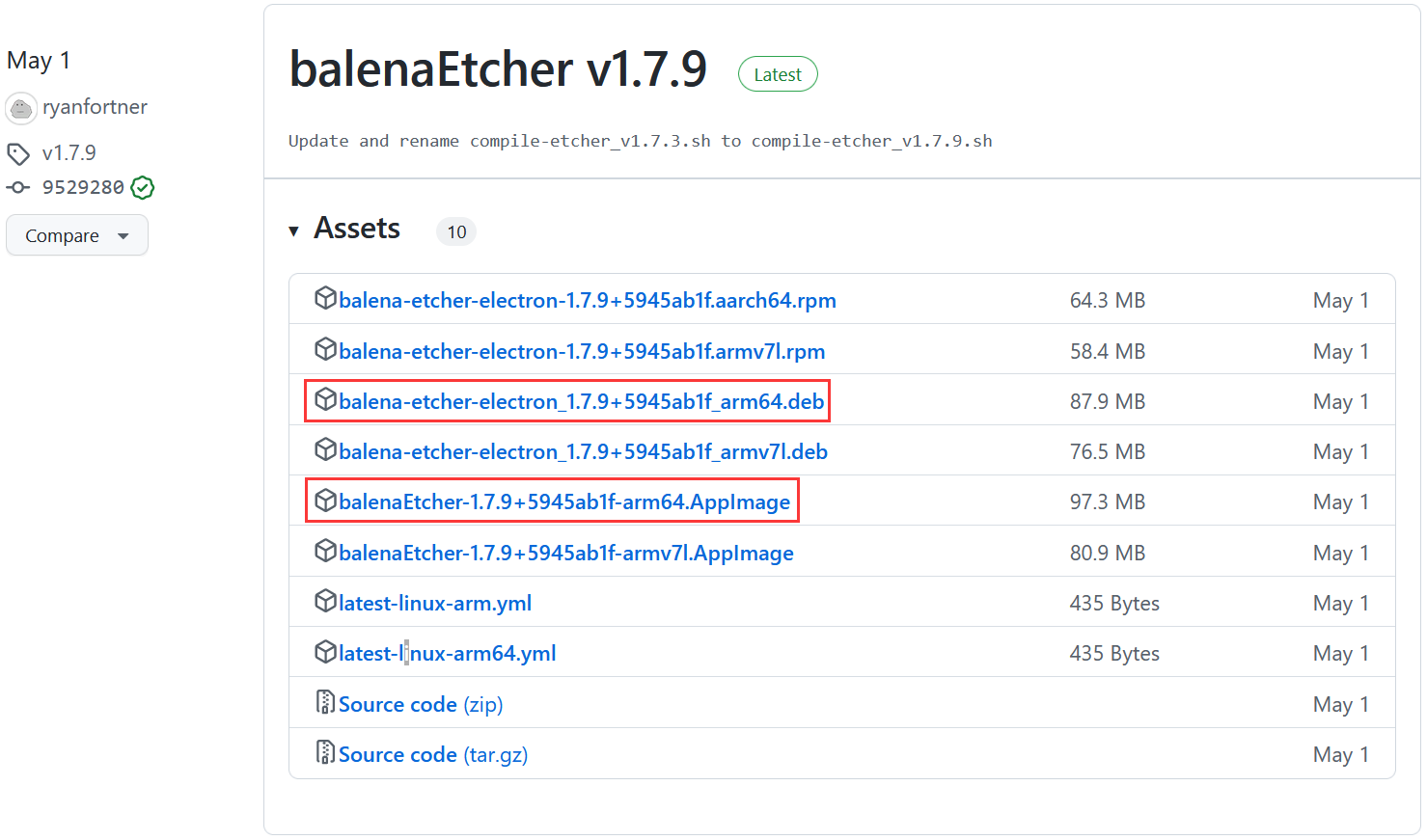

How to install and use the deb version of balenaEtcher:
- The deb version of balenaEtcher installation command is as follows:
orangepi@orangepi:~$ sudo apt install -y \
--fix-broken ./balena-etcher-electron_1.7.9+5945ab1f_arm64.deb
- After the deb version of balenaEtcher is installed, it can be opened in the Application
- The interface after balenaEtcher is opened is as follows:
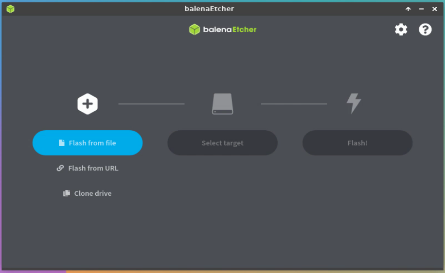

How to use AppImage version of balenaEtcher:
- First add permissions to balenaEtcher
orangepi@orangepi:~/Desktop$ chmod +x balenaEtcher-1.7.9+5945ab1f-arm64.AppImage
- Then select the AppImage version balenaEtcher, then click the right mouse button, and then click Execute to open balenaEtcher
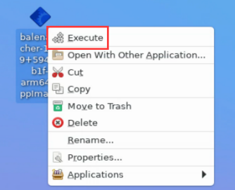

How to install BaoTa Linux panel
|
BaoTa Linux panel is a server management software that improves the efficiency of operation and maintenance. It supports one-click configuration of more than 100 server management functions such as LAMP/LNMP/cluster/monitoring/website/FTP/database/JAVA (excerpted from BaoTa Linux official website) |
- First, you need to expand the size of the/tmp space. After setting, you need to restart the linux system of the development board. The command is as follows:
orangepi@orangepi:~$ sudo sed -i 's/nosuid/&,size=2G/' /etc/fstab
orangepi@orangepi:~$ sudo reboot
- After restarting, you can see that the size of /tmp space has changed to 2G
|
orangepi@orangepi:~$ df -h | grep "/tmp" tmpfs 2.0G 12K 2.0G 1% /tmp |
- Then enter the following command in the Linux system to start the installation of the BaoTa
|
orangepi@orangepi:~$ sudo install_bt_panel.sh |
- Then the installer will remind whether to install Bt-Panel to the /www folder, and then enter y
|
+---------------------------------------------------------------------- | Bt-WebPanel FOR CentOS/Ubuntu/Debian +---------------------------------------------------------------------- | Copyright © 2015-2099 BT-SOFT(http://www.bt.cn) All rights reserved. +---------------------------------------------------------------------- | The WebPanel URL will be http://SERVER_IP:8888 when installed. +----------------------------------------------------------------------
Do you want to install Bt-Panel to the /www directory now?(y/n): y |
- The next thing to do is to wait patiently. When you see the following print information output from the terminal, it means that the BaoTa has been installed. The entire installation process takes about 34 minutes, and there may be some differences depending on the network speed

At this time, enter the panel address shown above in the browser to open the login interface of the BaoTa Linux panel, and then enter the username and password shown in the above figure at the corresponding position to log in.
After successfully logging into the pagoda, the following welcome interface will pop up. First, please read the user notice in the middle and drag it to the bottom, then you can select "I have agreed and read the "User Agreement"", and then click "Enter the panel" You can enter the BaoTa


If you do not have an account, you can go to the official website of the BaoTa (http://www.aapanel.com/) to register
The final displayed interface is as shown in the figure below. You can intuitively see some status information of the Linux system on the development board, such as load status, CPU usage, memory usage, and storage space usage, etc.


- For more functions of the pagoda, you can refer to the following information to explore by yourself
|
Manual: http://docs.bt.cn Forum address: https://www.bt.cn/bbs GitHub Link: https://github.com/aaPanel/BaoTa |
Setting Chinese environment and installing Chinese input method
|
Note, before installing the Chinese input method, please make sure that the Linux system used by the development board is a desktop system. |
How to install Debian system
First set the default locale to Chinese
- Enter the following command to start the configuration locale
orangepi@orangepi:~$ sudo dpkg-reconfigure locales
- Then select zh_CN.UTF-8 UTF-8 in the pop-up interface (move up and down through the up and down direction keys on the keyboard, select through the space bar, and finally move the cursor to <OK> through the Tab key, and then return to car)

- Then set the default locale as zh_CN.UTF-8
- After exiting the interface, the locale setting will start, and the output displayed on the command line is as follows
orangepi@orangepi:~$ sudo dpkg-reconfigure locales
Generating locales (this might take a while)...
en_US.UTF-8... done
zh_CN.UTF-8... done
Generation complete.


- Then open Input Method

- Then Select OK

- Then Select Yes

- Then Select fcitx

- Then Select OK

Then restart the Linux system to make the configuration take effect
Then open Fcitx configuration

- Then click the + sign in the position shown in the figure below

- Then search Google Pinyin and click OK

- Then bringGoogle Pinyin to the front


- Then open the Geany editor to test the Chinese input method

- The Chinese input method test is as follows

The Chinese and English input methods can be switched through the Ctrl+Space shortcut key
If the entire system needs to be displayed in Chinese, you can set the variables in /etc/default/locale to zh_CN.UTF-8
|
orangepi@orangepi:~$ sudo vim /etc/default/locale # File generated by update-locale LC_MESSAGES=zh_CN.UTF-8 LANG=zh_CN.UTF-8 LANGUAGE=zh_CN.UTF-8 |
- Then restart the system and you can see that the system is displayed in Chinese

How to install Ubuntu 20.04 system
- Open first Language Support

- Then find the Chinese (China) option

- Then please use the left mouse button to select Chinese (China) and hold it down, then drag it up to the initial position, and the display after dragging is as shown in the figure below:

|
Note that this step is not easy to drag, please be patient and try a few more times. |
- Then select Apply System-Wide to apply the Chinese settings to the entire system

- Then set Keyboard input method system as fcitx

Then restart the Linux system to make the configuration take effect
After re-entering the system, please choose not to ask me again in the following interface, and then please decide whether the standard folder should also be updated to Chinese according to your preferences

- Then you can see that the desktop is displayed in Chinese

- Then we can open Geany to test the Chinese input method, the opening method is as shown in the figure below

- After openingGeany, the default is English input method, we can switch to Chinese input method through Ctrl+Spaceshortcut key, and then we can input Chinese

How to install Ubuntu 22.04 system
- Open first Language Support
- Then find the Chinese (China) option

- Then please use the left mouse button to select Chinese (China) and hold it down, then drag it up to the initial position, and the display after dragging is as shown in the figure below:

|
Note that this step is not easy to drag, please be patient and try a few more times. |
- Then select Apply System-Wide to apply the Chinese settings to the entire system

Then restart the Linux system to make the configuration take effect
After re-entering the system, please choose not to ask me again in the following interface, and then please decide whether the standard folder should also be updated to Chinese according to your preferences
- Then you can see that the desktop is displayed in Chinese
- Then open the Fcitx5 configuration program

- Then choose to use Pinyin input method

- The interface after selection is as shown below, and then click OK

- Then we can open Geanyto test the Chinese input method, the opening method is as shown in the figure below
- After opening Geany, the default is English input method, we can switch to Chinese input method through Ctrl+Space shortcut key, and then we can input Chinese

How to remotely log in to the desktop of the Linux system
Remote login using NoMachine
|
Please make sure that the Ubuntu or Debian system installed on the development board is a desktop version. In addition, NoMachine also provides detailed usage documents. It is strongly recommended to read this document to familiarize yourself with the use of NoMachine. The document link is as follows: Please make sure that the Ubuntu or Debian system installed on the development board is a desktop version. In addition, NoMachine also provides detailed usage documents. It is strongly recommended to read this document to familiarize yourself with the use of NoMachine. The document link is as follows: |
|
NoMachine supports Windows, Mac, Linux, iOS and Android platforms, so we can remotely log in and control the Orange Pi development board through NoMachine on a variety of devices. The following demonstrates how to remotely log in to the Linux system desktop of the Orange Pi development board through NoMachine in Windows. For installation methods on other platforms, please refer to the official documentation of NoMachine. |
|
Before operation, please make sure that the Windows computer and the development board are in the same LAN, and you can log in to the Ubuntu or Debian system of the development board through ssh. |
First download the installation package of the NoMachine software Linux arm64 deb version, and then install it in the Linux system of the development board
- Since RK3566 is an SOC with ARMv8 architecture, the system we use is Ubuntu or Debian, so here we need to download the NoMachine for ARM ARMv8 DEB installation package. The download link is as follows:
Note that this download link may change, please look for the deb package of the Armv8/Arm64 version.
- In addition, you can also download the NoMachine installation package in the official tool

First enter the remote login software-NoMachine folder

Then download the arm64 version of the deb installation package
Then upload the downloaded nomachine_x.x.x_x_arm64.deb to the Linux system of the development board
Then use the following command to install NoMachine in the Linux system of the development board NoMachine
orangepi@orangepi:~$ sudo dpkg -i nomachine_x.x.x_x_arm64_arm64.deb


- Then download the installation package of the Windows version of the NoMachine software, the download address is as follows
|
Note that this download link may change. |

Then install NoMachine in Windows, please restart the computer after installation
Then open NoMachine in Window NoMachine

- After NoMachine starts, it will automatically scan other devices installed with NoMachine in the LAN. After entering the main interface of NoMachine, you can see that the development board is already in the list of connectable devices, and then click the position shown in the red box in the figure below You can start to log in to the Linux system desktop of the development board

- Then Click OK

- Then enter the user name and password of the Linux system of the development board in the corresponding position in the figure below, and then click OK to start logging in

Then click OK in the next interface
Finally, you can see the desktop of the development board Linux system

Use VNC to log in remotely
|
Before operation, please make sure that the Windows computer and the development board are in the same LAN, and you can log in to the Ubuntu or Debian system of the development board through ssh. Ubuntu20.04 has many problems testing VNC, please do not use this method. |
- First run the set_vnc.sh script to set up vnc, remember to add sudo permission
orangepi@orangepi:~$ sudo set_vnc.sh
You will require a password to access your desktops.
Password: # Set the vnc password here, 8 charactersVerify: # Set the vnc password here, 8 characters
Would you like to enter a view-only password (y/n)? n
xauth: file /root/.Xauthority does not exist
New 'X' desktop is orangepicm4:1
Creating default startup script /root/.vnc/xstartupStarting applications specified in /root/.vnc/xstartup
Log file is /root/.vnc/orangepicm4:1.log
Killing Xtightvnc process ID 3047
New 'X' desktop is orangepicm4:1
Starting applications specified in /root/.vnc/xstartupLog file is /root/.vnc/orangepicm4:1.log
The steps to use MobaXterm software to connect to the Linux system desktop of the development board are as follows:
- First click on Session, then select VNC, then fill in the IP address and port of the development board, and finally click OK to confirm
- Then enter the VNC password set earlier
After successful login, the interface is displayed as shown in the figure below, and then you can remotely operate the desktop of the Linux system on the development board


Some programming language tests supported by Linux system
Debian Bullseye System
Debian Bullseye has a gcc compilation tool chain installed by default, which can directly compile C language programs in the Linux system of the development board
- The version of gcc is as follows
orangepi@orangepi:~$ gcc --version
gcc (Debian 10.2.1-6) 10.2.1 20210110
Copyright (C) 2020 Free Software Foundation, Inc.
This is free software; see the source for copying conditions. There is NO
warranty; not even for MERCHANTABILITY or FITNESS FOR A PARTICULAR PURPOSE.
- Write the hello_world.c program in C language
- printf("Hello World!\n");
- return 0;
orangepi@orangepi:~$ vim hello_world.c
#include <stdio.h>
int main(void){
}
- Then compile and run hello_world.c
orangepi@orangepi:~$ gcc -o hello_world hello_world.c
orangepi@orangepi:~$ ./hello_world
Hello World!
Debian Bullseye has Python3 installed by default
- The specific version of Python is as follows
orangepi@orangepi:~$ python3
Python 3.9.2 (default, Feb 28 2021, 17:03:44)
[GCC 10.2.1 20210110] on linux
Type "help", "copyright", "credits" or "license" for more information.
>>>
- Write hello_world.py program in Python language
orangepi@orangepi:~$ vim hello_world.py
print('Hello World!')
- The result of running hello_world.pyis as follows
orangepi@orangepi:~$ python3 hello_world.py
Hello World!
Debian Bullseye does not install Java compilation tools and runtime environment by default
- You can use the following command to install openjdk, the latest version in Debian Bullseye is openjdk-17
orangepi@orangepi:~$ sudo apt install -y openjdk-17-jdk
- After installation, you can check the version of Java
orangepi@orangepi:~$ java --version
- Write the Java version hello_world.java
- public static void main(String[] args)
- {
- System.out.println("Hello World!");
- }
orangepi@orangepi:~$ vim hello_world.java
public class hello_world
{
}
- Then compile and run hello_world.java
orangepi@orangepi:~$ javac hello_world.java
orangepi@orangepi:~$ java hello_world
Hello World!
Debian Bookworm System
Debian Bookworm is installed with the gcc compilation tool chain by default, which can directly compile C language programs in the Linux system of the development board
- The version of gcc is as follows
orangepi@orangepi:~$ gcc --version
gcc (Debian 12.2.0-14) 12.2.0
Copyright (C) 2022 Free Software Foundation, Inc.
This is free software; see the source for copying conditions. There is NO
warranty; not even for MERCHANTABILITY or FITNESS FOR A PARTICULAR PURPOSE.
- Write the hello_world.c program in C language
- printf("Hello World!\n");
- return 0;
orangepi@orangepi:~$ vim hello_world.c
#include <stdio.h>
int main(void){
}
- Then compile and run hello_world.c
orangepi@orangepi:~$ gcc -o hello_world hello_world.c
orangepi@orangepi:~$ ./hello_world
Hello World!
Debian Bookworm has Python3 installed by default
- The specific version of Python is as follows
orangepi@orangepi:~$ python3
Python 3.11.2 (main, Mar 13 2023, 12:18:29) [GCC 12.2.0] on linux
Type "help", "copyright", "credits" or "license" for more information.
>>>
Use the Ctrl+D shortcut to exit python's interactive mode.
- Write hello_world.py program in Python language
orangepi@orangepi:~$ vim hello_world.py
print('Hello World!')
- The result of running hello_world.py is as follows
orangepi@orangepi:~$ python3 hello_world.py
Hello World!
Debian Bookworm does not install Java compilation tools and runtime environment by default
- You can use the following command to install openjdk, the latest version in Debian Bookworm is openjdk-17
orangepi@orangepi:~$ sudo apt install -y openjdk-17-jdk
- After installation, you can check the version of Java
orangepi@orangepi:~$ java --version
- Write the Java version hello_world.java
- public static void main(String[] args)
- {
- System.out.println("Hello World!");
- }
orangepi@orangepi:~$ vim hello_world.java
public class hello_world
{
}
- Then compile and run hello_world.java
orangepi@orangepi:~$ javac hello_world.java
orangepi@orangepi:~$ java hello_world
Hello World!
Ubuntu Focal system
Ubuntu Focal has a gcc compilation tool chain installed by default, which can directly compile C language programs in the Linux system of the development board
- The version of gcc is as follows
orangepi@orangepi:~$ gcc --version
gcc (Ubuntu 9.4.0-1ubuntu1~20.04.1) 9.4.0
Copyright (C) 2019 Free Software Foundation, Inc.
This is free software; see the source for copying conditions. There is NO
warranty; not even for MERCHANTABILITY or FITNESS FOR A PARTICULAR PURPOSE.
- Write the hello_world.c program in C language
- printf("Hello World!\n");
- return 0;
orangepi@orangepi:~$ vim hello_world.c
#include <stdio.h>
int main(void){
}
- Then compile and run hello_world.c
orangepi@orangepi:~$ gcc -o hello_world hello_world.c
orangepi@orangepi:~$ ./hello_world
Hello World!
Ubuntu Focal has Python3 installed by default
- The specific version of Python3 is as follows
orangepi@orangepi:~$ python3
Python 3.8.10 (default, Nov 14 2022, 12:59:47)
[GCC 9.4.0] on linux
Type "help", "copyright", "credits" or "license" for more information.
>>>
- Write hello_world.py program in Python language
orangepi@orangepi:~$ vim hello_world.py
print('Hello World!')
- The result of running hello_world.py is as follows
orangepi@orangepi:~$ python3 hello_world.py
Hello World!
Ubuntu Focal does not install Java compilation tools and operating environment by default
- You can use the following command to install openjdk-17
orangepi@orangepi:~$ sudo apt install -y openjdk-17-jdk
- After installation, you can check the version of Java
orangepi@orangepi:~$ java --version
openjdk 17.0.2 2022-01-18
OpenJDK Runtime Environment (build 17.0.2+8-Ubuntu-120.04)
OpenJDK 64-Bit Server VM (build 17.0.2+8-Ubuntu-120.04, mixed mode, sharing)
- Write the Java version hello_world.java
- public static void main(String[] args)
- {
- System.out.println("Hello World!");
- }
orangepi@orangepi:~$ vim hello_world.java
public class hello_world
{
}
- Then compile and run hello_world.java
orangepi@orangepi:~$ javac hello_world.java
orangepi@orangepi:~$ java hello_world
Hello World!
Ubuntu Jammy system
Ubuntu Jammy has a gcc compilation tool chain installed by default, which can directly compile C language programs in the Linux system of the development board
- The version of gcc is as follows
orangepi@orangepi:~$ gcc --version
gcc (Ubuntu 11.2.0-19ubuntu1) 11.2.0
Copyright (C) 2021 Free Software Foundation, Inc.
This is free software; see the source for copying conditions. There is NO
warranty; not even for MERCHANTABILITY or FITNESS FOR A PARTICULAR PURPOSE.
- Write the hello_world.c program in C language
- printf("Hello World!\n");
- return 0;
orangepi@orangepi:~$ vim hello_world.c
#include <stdio.h>
int main(void){
}
- Then compile and run hello_world.c
orangepi@orangepi:~$ gcc -o hello_world hello_world.c
orangepi@orangepi:~$ ./hello_world
Hello World!
Ubuntu Jammy has Python3 installed by default
- The specific version of Python3 is as follows
orangepi@orangepi:~$ python3
Python 3.10.4 (main, Apr 2 2022, 09:04:19) [GCC 11.2.0] on linux
Type "help", "copyright", "credits" or "license" for more information.
>>>
- Write hello_world.py program in Python language
orangepi@orangepi:~$ vim hello_world.py
print('Hello World!')
- The result of running hello_world.py is as follows
orangepi@orangepi:~$ python3 hello_world.py
Hello World!
Ubuntu Jammy does not install Java compilation tools and runtime environment by default
- You can use the following command to install openjdk-18
orangepi@orangepi:~$ sudo apt install -y openjdk-18-jdk
- After installation, you can check the version of Java
orangepi@orangepi:~$ java --version
openjdk 18-ea 2022-03-22
OpenJDK Runtime Environment (build 18-ea+36-Ubuntu-1)
OpenJDK 64-Bit Server VM (build 18-ea+36-Ubuntu-1, mixed mode, sharing)
- Write the Java version hello_world.java
- public static void main(String[] args)
- {
- System.out.println("Hello World!");
- }
orangepi@orangepi:~$ vim hello_world.java
public class hello_world
{
}
- Then compile and run hello_world.java
orangepi@orangepi:~$ javac hello_world.java
orangepi@orangepi:~$ java hello_world
Hello World!
How to install QT
- Use the script below to install QT5 and QT Creator
orangepi@orangepi:~$ install_qt.sh
After installation, the version number of QT will be automatically printed
- The qt version that comes with Ubuntu 20.04 is 5.12.8
orangepi@orangepi:~$ install_qt.sh
......
QMake version 3.1
Using Qt version 5.12.8 in /usr/lib/aarch64-linux-gnu
- The QT version that comes with Ubuntu 22.04 is 5.15.3
orangepi@orangepi:~$ install_qt.sh
......
QMake version 3.1
Using Qt version 5.15.3 in /usr/lib/aarch64-linux-gnu
- The QT version that comes with Debian11 is 5.15.2
orangepi@orangepi:~$ install_qt.sh
......
QMake version 3.1
Using Qt version 5.15.2 in /usr/lib/aarch64-linux-gnu
- The QT version that comes with Debian12 is 5.15.8
orangepi@orangepi:~$ install_qt.sh
......
QMake version 3.1
Using Qt version 5.15.8 in /usr/lib/aarch64-linux-gnu
- Then you can see the startup icon of QT Creator in Applications

You can also use the following command to open QT Creator
|
orangepi@orangepi:~$ qtcreator |
|
During the startup process of QT and QT application, if the following error is prompted, please ignore it directly, this error will not affect the operation of the application.
libGL error: failed to load driver: rockchip libGL error: failed to create dri screen libGL error: failed to load driver: rockchip |
- The interface after QT Creator is opened is as follows

The version of QT Creator is as follows
- The default version of QT Creator in Ubuntu20.04 is as follows
- The default version of QT Creator in Ubuntu22.04 is as follows
- The default version of QT Creator in Debian11 is as follows
- The default version of QT Creator in Debian12 is as follows


Then set the QT
- open first Help->About Plugins...
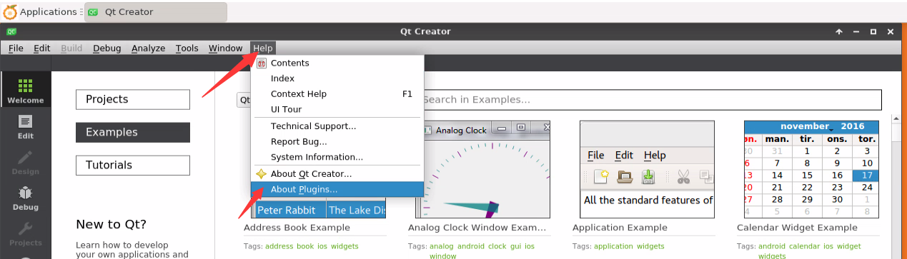
- Then remove the tick of ClangCodeModel
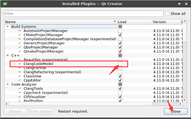
After setting, you need to restart QT Creator
Then make sure the GCC compiler used by QT Creator, if the default is Clang, please modify it to GCC
Debian12 please skip this step.


- Then you can open a sample code

- After clicking the sample code, the corresponding instruction document will be opened automatically, you can read the instruction carefully

- Then click next Configure Project

- Then click the green triangle in the lower left corner to compile and run the sample code

- After waiting for a period of time, the interface shown in the figure below will pop up, which means that QT can compile and run normally

How to install ROS
How to install ROS 1 Noetic on Ubuntu 20.04
- The current active version of ROS 1 is as follows, and the recommended version is Noetic Ninjemys


- The official installation document link of ROS 1 Noetic Ninjemys is as follows:
- In the official installation document of ROS Noetic Ninjemys, Ubuntu recommends using Ubuntu20.04, so please make sure that the system used by the development board is Ubuntu20.04 desktop system

- Then use the following script to install ros1
|
orangepi@orangepicm4:~$ install_ros.sh ros1 |
- Before using the ROS tool, you first need to initialize rosdep, and then you can quickly install some system dependencies and some core components in ROS when compiling the source code
- The read operation timed out
- rosdep update
|
Note that running the following command needs to ensure that the development board can access github normally, otherwise an error will be reported due to network problems.
Hit https://raw.githubusercontent.com/ros/rosdistro/master/rosdep/base.yaml ERROR: error loading sources list: |
|
orangepi@orangepi:~$ source /opt/ros/noetic/setup.bash orangepi@orangepi:~$ sudo rosdep init Wrote /etc/ros/rosdep/sources.list.d/20-default.list Recommended: please run
orangepi@orangepi:~$ rosdep update reading in sources list data from /etc/ros/rosdep/sources.list.d Hit https://raw.githubusercontent.com/ros/rosdistro/master/rosdep/osx-homebrew.yaml Hit https://raw.githubusercontent.com/ros/rosdistro/master/rosdep/base.yaml Hit https://raw.githubusercontent.com/ros/rosdistro/master/rosdep/python.yaml Hit https://raw.githubusercontent.com/ros/rosdistro/master/rosdep/ruby.yaml Hit https://raw.githubusercontent.com/ros/rosdistro/master/releases/fuerte.yaml Query rosdistro index https://raw.githubusercontent.com/ros/rosdistro/master/index-v4.yaml Skip end-of-life distro "ardent" Skip end-of-life distro "bouncy" Skip end-of-life distro "crystal" Skip end-of-life distro "dashing" Skip end-of-life distro "eloquent" Add distro "foxy" Add distro "galactic" Skip end-of-life distro "groovy" Add distro "humble" Skip end-of-life distro "hydro" Skip end-of-life distro "indigo" Skip end-of-life distro "jade" Skip end-of-life distro "kinetic" Skip end-of-life distro "lunar" Add distro "melodic" Add distro "noetic" Add distro "rolling" updated cache in /home/orangepi/.ros/rosdep/sources.cache |
- Then open a command line terminal window on the desktop, and then use the test_ros.sh script to start a small turtle routine to test whether ROS can be used normally
|
orangepi@orangepi:~$ test_ros.sh |
- After running the test_ros.sh script, a little turtle as shown in the figure below will pop up

- Then please keep the terminal window just opened at the top

- At this time, press the direction keys on the keyboard to control the little turtle to move up, down, left, and right

How to install ROS 2 Galactic on Ubuntu 20.04
- The current active version of ROS 2 is as follows, and the recommended version is Galactic Geochelone


- The link to the official ROS 2 Galactic Geochelone installation documentation is as follows:
|
docs.ros.org/en/galactic/Installation.html http://docs.ros.org/en/galactic/Installation/Ubuntu-Install-Debians.html |
In the official ROS 2 Galactic Geochelone installation document, Ubuntu Linux recommends using Ubuntu 20.04, so please make sure that the system used by the development board is the Ubuntu 20.04 desktop system. There are several ways to install ROS 2. The following demonstrates how to install it through Debian packages ROS 2 Galactic Geochelone
Use the install_ros.sh script to install ros2
|
orangepi@orangepi:~$ install_ros.sh ros2 |
- The install_ros.sh script will automatically run the ros2 -h command after installing ros2. If you can see the following print, it means that the ros2 installation is complete
- -h, --help show this help message and exit
- action Various action related sub-commands
- bag Various rosbag related sub-commands
- component Various component related sub-commands
- daemon Various daemon related sub-commands
- doctor Check ROS setup and other potential issues
- interface Show information about ROS interfaces
- launch Run a launch file
- lifecycle Various lifecycle related sub-commands
- multicast Various multicast related sub-commands
- node Various node related sub-commands
- param Various param related sub-commands
- pkg Various package related sub-commands
- run Run a package specific executable
- security Various security related sub-commands
- service Various service related sub-commands
- topic Various topic related sub-commands
- wtf Use `wtf` as alias to `doctor`
- Call `ros2 <command> -h` for more detailed usage.
|
usage: ros2 [-h] Call `ros2 <command> -h` for more detailed usage. ...
|
- Then you can use the test_ros.sh script to test whether ROS 2 is installed successfully. If you can see the following print, it means that ROS 2 can run normally
|
orangepi@orangepicm4:~$ test_ros.sh [INFO] [1671174101.200091527] [talker]: Publishing: 'Hello World: 1' [INFO] [1671174101.235661048] [listener]: I heard: [Hello World: 1] [INFO] [1671174102.199572327] [talker]: Publishing: 'Hello World: 2' [INFO] [1671174102.204196299] [listener]: I heard: [Hello World: 2] [INFO] [1671174103.199580322] [talker]: Publishing: 'Hello World: 3' [INFO] [1671174103.204019965] [listener]: I heard: [Hello World: 3] |
- Run the following command to open rviz2
|
orangepi@orangepi:~$ source /opt/ros/galactic/setup.bash orangepi@orangepi:~$ ros2 run rviz2 rviz2 |

- For how to use ROS, please refer to the documentation of ROS 2
How to install ROS 2 Humble on Ubuntu 22.04
- Use the install_ros.sh script to install ros2
orangepi@orangepi:~$ install_ros.sh ros2
- The install_ros.sh script will automatically run the ros2 -h command after installing ros2. If you can see the following print, it means that the ros2 installation is complete
- -h, --help show this help message and exit
- action Various action related sub-commands
- bag Various rosbag related sub-commands
- component Various component related sub-commands
- daemon Various daemon related sub-commands
- doctor Check ROS setup and other potential issues
- interface Show information about ROS interfaces
- launch Run a launch file
- lifecycle Various lifecycle related sub-commands
- multicast Various multicast related sub-commands
- node Various node related sub-commands
- param Various param related sub-commands
- pkg Various package related sub-commands
- run Run a package specific executable
- security Various security related sub-commands
- service Various service related sub-commands
- topic Various topic related sub-commands
- wtf Use `wtf` as alias to `doctor`
- Call `ros2 <command> -h` for more detailed usage.
|
usage: ros2 [-h] Call `ros2 <command> -h` for more detailed usage. ...
|
- Then you can use the test_ros.sh script to test whether ROS 2 is installed successfully. If you can see the following print, it means that ROS 2 can run normally
|
orangepi@orangepicm4:~$ test_ros.sh [INFO] [1671174101.200091527] [talker]: Publishing: 'Hello World: 1' [INFO] [1671174101.235661048] [listener]: I heard: [Hello World: 1] [INFO] [1671174102.199572327] [talker]: Publishing: 'Hello World: 2' [INFO] [1671174102.204196299] [listener]: I heard: [Hello World: 2] [INFO] [1671174103.199580322] [talker]: Publishing: 'Hello World: 3' [INFO] [1671174103.204019965] [listener]: I heard: [Hello World: 3] |
- Run the following command to open rviz2
|
orangepi@orangepi:~$ source /opt/ros/humble/setup.bash orangepi@orangepi:~$ ros2 run rviz2 rviz2 |

- Reference documents
|
http://docs.ros.org/en/humble/index.html http://docs.ros.org/en/humble/Installation/Ubuntu-Install-Debians.html |
How to install kernel header files
- The Linux image released by OPi comes with the deb package of the kernel header file by default, and the storage location is /opt/
orangepi@orangepi:~$ ls /opt/linux-headers*
/opt/linux-headers-legacy-rockchip-rk356x_x.x.x_arm64.deb
- Use the following command to install the deb package of the kernel header file
|
The name of the kernel header file deb package needs to be replaced with the actual name, please do not copy it. |
|
orangepi@orangepi:~$ sudo dpkg -i /opt/linux-headers-legacy-rockchip-rk356x_1.x.x_arm64.deb |
- After installation, you can see the folder where the kernel header files are located under /usr/src
|
orangepi@orangepi:~$ ls /usr/src linux-headers-5.10.160-rockchip-rk356x |
Then you can write a hello kernel module to test the kernel header file
- First write the code of the hello kernel module, as follows:
- printk("Hello Orange Pi -- init\n");
- return 0;
- printk("Hello Orange Pi -- exit\n");
- return;
orangepi@orangepi:~$ vim hello.c
#include <linux/init.h>
#include <linux/module.h>
static int hello_init(void){
}
static void hello_exit(void)
{
}
module_init(hello_init);module_exit(hello_exit);
MODULE_LICENSE("GPL");- Then write the Makefile for compiling the hello kernel module, as follows:
- make -C $(KDIR) M=$(PWD) modules
- rm -f *.ko *.o *.mod.o *.mod *.symvers *.cmd *.mod.c *.order
orangepi@orangepi:~$ vim Makefile
ifneq ($(KERNELRELEASE),)
obj-m:=hello.o
else
KDIR :=/lib/modules/$(shell uname -r)/build
PWD :=$(shell pwd)
all:
clean:
endif
- Then use the make command to compile the hello kernel module. The output of the compilation process is as follows:
- CC [M] /home/orangepi/hello.o
- MODPOST /home/orangepi/Module.symvers
- CC [M] /home/orangepi/hello.mod.o
- LD [M] /home/orangepi/hello.ko
If there is a problem with compiling the code you copied here, please go to the official tool to download the source code and upload it to the Linux system of the development board for testing.
orangepi@orangepi:~$ make
make -C /lib/modules/5.10.160-rockchip-35xx/build M=/home/orangepi modules
make[1]: Entering directory '/usr/src/linux-headers-5.10.160-rockchip-rk35xx'
make[1]: Leaving directory '/usr/src/linux-headers-5.10.160-rockchip-rk35xx'
- After compiling, the hello.ko kernel module will be generated
orangepi@orangepi:~$ ls *.ko
hello.ko
- Use the insmodcommand to insert the hello.ko kernel module into the kernel
orangepi@orangepi:~$ sudo insmod hello.ko
- Then use the demsg command to view the output of the hello.ko kernel module. If you can see the output below, it means that thehello.ko kernel module is loaded correctly.
orangepi@orangepi:~$ dmesg | grep "Hello"
[ 2871.893988] Hello Orange Pi -- init
- Use the rmmod command to uninstall the hello.ko kernel module
orangepi@orangepi:~$ sudo rmmod hello
orangepi@orangepi:~$ dmesg | grep "Hello"
[ 2871.893988] Hello Orange Pi -- init
[ 3173.800892] Hello Orange Pi -- exit

Use of Raspberry Pi 5 Inch screen
How to assemble the Raspberry Pi 5 Inch screen
First prepare the required accessories
- Raspberry Pi 5-inch MIPI LCD display + Touch screen
Raspberry Pi 5-inch MIPI LCD display + Touch screenis shown in the figure below
- 15pin MIPI cable


- Then connect the 15pin MIPI cable to the Raspberry Pi 5-inch screen as shown in the figure below (note the orientation of the insulating surface)

- Finally connect to the LCD interface of the Orange Pi CM4 development board

How to open Raspberry Pi 5-inch screen configuration
By default, the Linux image does not enable the configuration of the Raspberry Pi 5-inch screen. If you need to use the Raspberry Pi 5-inch screen, you need to manually open it.
The steps to open the mipi lcd configuration are as follows:
- First run orangepi-config, common users remember to add sudo permission
orangepi@orangepi:~$ sudo orangepi-config
- Then select System
- Then select Hardware
- Then use the arrow keys on the keyboard to navigate to raspi-7inch-touchscreen, and then use the space to select
- Then select <Save> Save

- Then select <Back>
- Then select <Reboot> Restart the system for the configuration to take effect
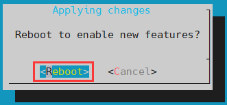
The above settings will eventually add the configuration of overlays=raspi-7inch-touchscreen to /boot/orangepiEnv.txt. After setting, you can check it first. If this configuration does not exist, then there is a problem with the settings.
If you find it troublesome to use orangepi-config, you can also use the vim editor to open /boot/orangepiEnv.txt, and then add the configuration of overlays=raspi-7inch-touchscreen is also possible.
orangepi@orangepi:~$ cat /boot/orangepiEnv.txt | grep "raspi"overlays=raspi-7inch-touchscreen # sample configuration


- After startup, you can see the display of the LCD screen as follows:

The method of server version image rotation display direction
- Add extraargs=fbcon=rotate:the direction to rotate in /boot/orangepiEnv.txt This line configuration can set the direction displayed by the server version of the Linux system, where the number after fbcon=rotate: can be set as:
0: normal screen (default is landscape)
1: Turn clockwise 90 degrees
2: Flip 180 degrees
3: Turn clockwise 270 degrees
orangepi@orangepi:~$ sudo vim /boot/orangepiEnv.txt
overlays=lcd1
extraargs=cma=64M fbcon=rotate:3
Note that if there is the line extraargs=cma=64M in /boot/orangepiEnv.txt by default, the configuration fbcon=rotate:3 can be added after extraargs=cma=64M (separated by spaces).
- Then restart the Linux system and you can see that the direction displayed on the LCD screen has been rotated
Method of rotating display and touch direction of desktop version image
- First open Display Settings in Linux

Then select the direction you want to rotate in Rotation
None: no rotation
Left: rotate left 90 degrees
Inverted: Flip up and down, which is equivalent to rotating 180 degrees
Right: rotate right 90 degrees
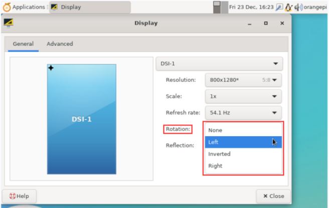

- Then click Apply

- Then select Keep this configuration

At this point, the screen display has been rotated, and then close the Display program
The above steps will only select the display direction, and will not rotate the direction of the touch. Use the set_lcd_rotate.sh script to rotate the direction of the touch. After the script is set, it will automatically restart, and then you can test whether the touch has been used normally.
- None: no rotation
orangepi@orangepi:~$ set_lcd_rotate.sh none
- Left: rotate left 90 degrees
orangepi@orangepi:~$ set_lcd_rotate.sh left
- Inverted: Flip up and down, which is equivalent to rotating 180 degrees
orangepi@orangepi:~$ set_lcd_rotate.sh inverted
- Right: rotate right 90 degrees
orangepi@orangepi:~$ set_lcd_rotate.sh right
The set_lcd_rotate.sh script mainly does four things:
1. Rotate the direction displayed by the framebuffer2. Rotate the direction of the touch
3. Turn off the boot logo
4. Restart the system
Rotating the touch direction is achieved by adding the line Option "TransformationMatrix" "x x x x x x x x x" to /usr/share/X11/xorg.conf.d/40-libinput.conf Where "x x x x x x x x x" is configured differently for different directions.
- Touch rotation reference
How to use the eDP screen
Assembly method of eDP screen
Currently only one eDP screen is compatible, including the following accessories:
0.5 pitch 30pin single-head cable in the same direction
eDP display
Connect the 30pin eDP interface of the screen and the eDP interface of the development board with a 30pin single-head cable in the same direction
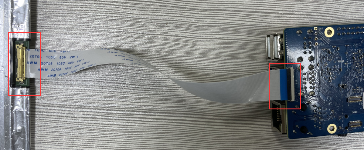


How to open the eDP screen configuration
|
Note that the method described below is only applicable to the adapted eDP screen. If the customer uses an unadapted screen, it cannot be turned on according to the following method. |
By default, the Linux image does not have the configuration to open the eDP screen. If you need to use the eDP screen, you need to open it manually.
The steps to open the eDP screen configuration are as follows:
First run orangepi-config, ordinary users remember to add > sudo permission
orangepi@orangepi:~$ sudo orangepi-config
Then select System
Then select Hardware
Then use the arrow keys on the keyboard to navigate to edp, and > then use the space to select
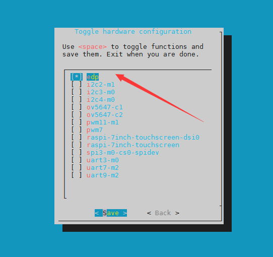
Then select <Save> to save
Then select <Back>
Then select <Reboot> to restart the system to make the > configuration take effect
The above settings will eventually add the configuration of overlays=edp to /boot/orangepiEnv.txt. After setting, you can check it first. If this configuration does not exist, then there is a problem with the settings.
If you find it troublesome to use orangepi-config, you can also use the vim editor to open /boot/orangepiEnv.txt, and then add the configuration of overlays=edp.
orangepi@orangepi:~$ cat /boot/orangepiEnv.txt | grep "edp"
overlays=edp #sample configuration
After startup, you can see the display of the eDP screen as follows:
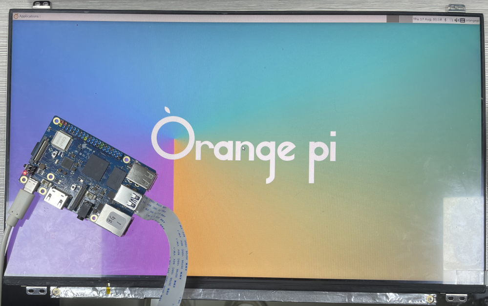


Instructions for using the switch logo
By default, the switch logo will only be displayed in the desktop version of the system
Set the bootlogo variable to false in /boot/orangepiEnv.txt to turn off the switch logo
orangepi@orangepi:~$ vim /boot/orangepiEnv.txt
verbosity=1
bootlogo=false
Set the bootlogo variable to true in /boot/orangepiEnv.txt to enable the switch logo
orangepi@orangepi:~$ vim /boot/orangepiEnv.txt
verbosity=1
bootlogo=true
The location of the boot logo image in the Linux system is
|
/usr/share/plymouth/themes/orangepi/watermark.png |
- After replacing the boot logo picture, you need to run the following command to take effect
|
orangepi@orangepi:~$ sudo update-initramfs -u |
How to use the ZFS file system
How to install ZFS
|
Before installing zfs, please make sure that the Linux image used is the latest version. In addition, if zfs is already installed in the system, it needs to be installed again. |
Before installing zfs, you need to install the kernel header file first. For the method of installing the kernel header file, please refer to the instructions in the section on the method of installing the kernel header file.
In Ubuntu20.04, Ubuntu22.04 and Debian11 systems, zfs cannot be installed directly through apt, because the default apt source zfs version is lower than 2.1.6, and there is a problem of incompatibility with rk Linux5.10 kernel. This problem is fixed in zfs version 2.1.6 and later.
To solve this problem, we provide a zfs deb package that can be installed normally, which can be downloaded from the official tool of the development board. Open the official tool, and enter the zfs-related deb package folders used by Ubuntu and Debian systems. You can see three types of deb packages: Ubuntu20.04, Ubuntu22.04 and Debian11. Please download the required version.

After downloading the zfs deb packages of the corresponding version, please upload them to the Linux system of the development board. For the upload method, please refer to the description in the section of the method of uploading files to the Linux system of the development board.
After the upload is complete, use the cd command in the command line of the development board Linux system to enter the directory of the deb package, and then use the following command to install the deb package of zfs.
|
orangepi@orangepi:~$ sudo apt install ./*.deb |
After the installation is complete, use the following command to see the zfs-related kernel modules:
|
orangepi@orangepi:~$ ls /lib/modules/5.10.160-rockchip-rk356x/updates/dkms/ icp.ko spl.ko zavl.ko zcommon.ko zfs.ko zlua.ko znvpair.ko zunicode.ko zzstd.ko |
Then restart the Linux system to see that the zfs kernel module will be automatically loaded:
|
orangepi@orangepi:~$ lsmod | grep "zfs" zfs 2801664 0 zunicode 327680 1 zfs zzstd 471040 1 zfs zlua 139264 1 zfs zcommon 69632 1 zfs znvpair 61440 2 zfs,zcommon zavl 16384 1 zfs icp 221184 1 zfs spl 77824 6 zfs,icp,zzstd,znvpair,zcommon,zavl |
In Debian12, the default version of zfs is 2.1.11, so we can install zfs directly through the following command. Again, please make sure that the system has installed the deb package of the kernel header file before installation.
|
orangepi@orangepi:~$ sudo apt install -y zfsutils-linux zfs-dkms |
Methods of creating ZFS pools
|
ZFS is based on storage pools, we can add multiple physical storage devices to the pool, and then allocate storage space from this pool. The following content is demonstrated based on the development board connected to an NVMe SSD and a USB flash drive. |
- First, we can use the lsblk command to view all storage devices on the development board. The current development board is connected to an NVMe SSD and a U disk. The output is as follows:

- Then enter the following command to create a ZFS pool, including two storage devices, NVMe SSD and U disk
|
orangepi@orangepi:~$ sudo zpool create -f pool1 /dev/nvme0n1 /dev/sda |
- Then use the zpool list command to see that the system has created a ZFS pool named pool1, and the size of the ZFS pool pool1 is the size of the NVME SSD plus the size of the U disk

- Then execute df -h to see that pool1 is mounted to the /pool1 directory
|
orangepi@orangepi:~$ df -h Filesystem Size Used Avail Use% Mounted on tmpfs 1.6G 18M 1.6G 2% /run /dev/mmcblk0p2 29G 6.0G 22G 22% / tmpfs 7.7G 46M 7.7G 1% /dev/shm tmpfs 5.0M 4.0K 5.0M 1% /run/lock tmpfs 7.7G 944K 7.7G 1% /tmp /dev/mmcblk0p1 1022M 115M 908M 12% /boot /dev/zram1 188M 4.5M 169M 3% /var/log tmpfs 1.6G 80K 1.6G 1% /run/user/1000 pool1 489G 9.3M 489G 1% /pool1 |
- Use the following command to see that the file system type of pool1 is zfs
|
orangepi@orangepi:~$ mount | grep pool1 pool1 on /pool1 type zfs (rw,xattr,noacl) |
- Then we can test copying a file to the ZFS pool
|
orangepi@orangepi:~$ sudo cp -v /usr/local/test.mp4 /pool1/ '/usr/local/test.mp4' -> '/pool1/test.mp4' |
Test the data deduplication function of ZFS
- The data deduplication function of ZFS is disabled by default, we need to execute the following command to enable it
orangepi@orangepi:~$ sudo zfs set dedup=on pool1
- Then do a simple test, first enter pool1, and then execute the following command to generate a random file with a size of 1G
|
orangepi@orangepi:~$ cd /pool1/ root@orangepi:/pool1$ sudo dd if=/dev/urandom of=test.1g bs=1M count=1024 1024+0 records in 1024+0 records out 1073741824 bytes (1.1 GB, 1.0 GiB) copied, 5.04367 s, 213 MB/s |
- Then use the following command to copy 1000 random files of size 1G
|
root@orangepi:/pool1$ for ((i=0; i<1000; i++)); do sudo cp test.1g $i.test.1g; done |
- Then use du -lh to see that there are currently 1002G of data in the pool, but in fact the size of the ZFS pool is only 504GB (the total capacity of SSD+U disk), which cannot hold such a large amount of data
|
root@orangepi:/pool1$ du -lh 1002G |
- Then use the zpool list command to see that only 1.01G is actually occupied, because these 1001 files are all duplicates, indicating that the data deduplication function is effective.

Test the data compression function of ZFS
- Because the stored data is different, the disk space saved by compression will also be different, so we choose to compress relatively large plain text files for compression testing, and execute the following commands to pack the /var/log/ and /etc/ directories into a tarball
orangepi@orangepi:~$ cd /pool1/
root@orangepi:/pool1$ sudo tar -cf text.tar /var/log/ /etc/
- Then the file size that can be seen through the ls -lh command and the space occupied in the ZFS pool are both 27M

- Then we enable compression in the ZFS pool pool1
|
root@orangepi:/pool1$ sudo zfs set compression=lz4 pool1 |
- Then execute the following command again to package the /var/log/ and /etc/ directories into a tar package
|
root@orangepi:/pool1$ sudo tar -cf text.tar /var/log/ /etc/ |
- At this time, you can see that the size of the text.tar file is still 27M, but it only occupies 9.47M in the ZFS pool, indicating that the file is compressed

How to shut down and restart the development board
During the running of the Linux system, if the Type-C power supply is directly unplugged, some data may be lost or damaged in the file system, so please use the poweroff command to shut down the Linux system of the development board before powering off. Then unplug the power again.
orangepi@orangepi:~$ sudo poweroff
The command to restart the Linux system is
orangepi@orangepi:~$ sudo reboot
Linux SDK——orangepi-build instructions
Compilation system requirements
|
We can cross-compile the Linux image of the development board on the x64 computer, or compile the Linux image of the development board on the Ubuntu22.04 system of the development board, please choose one according to your preference. If you use orangepi-build to compile the Linux image in the Ubuntu22.04 system of the development board, please do a good job of cooling (especially when the SSD starts). If the heat dissipation is not done well, it is prone to the error of file system runaway. |
Compile with the Ubuntu22.04 system of the development board
The Linux SDK, namely orangepi-build, supports running on the Ubuntu 22.04 of the development board (other systems have not been tested), so before downloading orangepi-build, please first ensure that the Ubuntu version installed on the development board is Ubuntu 22.04. The command to check the Ubuntu version installed on the development board is as follows. If the Release field does not display 22.04, it means that the current Ubuntu version does not meet the requirements. Please replace the system before performing the following operations.
test@test:~$ lsb_release -a
No LSB modules are available.
Distributor ID: Ubuntu
Description: Ubuntu 22.04 LTS
Release: 22.04
Codename: jammy
If the computer is installed with Windows system and there is no computer with Ubuntu 22.04 installed, you can consider using VirtualBox or VMwar to install an Ubuntu 22.04 virtual machine in the Windows system. But please be careful not to compile orangepi-build on the WSL virtual machine, because orangepi-build has not been tested in the WSL virtual machine, so it cannot be guaranteed that orangepi-build can be used normally in WSL.
The download address of the installation image of Ubuntu 22.04 amd64 version is:
https://mirrors.tuna.tsinghua.edu.cn/ubuntu-releases/22.04/ubuntu-22.04-desktop-amd64.iso
or
https://repo.huaweicloud.com/ubuntu-releases/22.04/ubuntu-22.04.1-desktop-amd64.iso
Get the source code of Linux sdk
Download orangepi-build from github
- The Linux sdk actually refers to the code of orangepi-build. orangepi-build is modified based on the armbian build system. Using orangepi-build, multiple versions of Linux images can be compiled. First download the code of orangepi-build, the command is as follows:
test@test:~$ sudo apt-get update
test@test:~$ sudo apt-get install -y git
test@test:~$ git clone https://github.com/orangepi-xunlong/orangepi-build.git -b next
Note that the Orange Pi 3B development board needs to download the source code of the next branch of orangepi-build. The above git clone command needs to specify the branch of the orangepi-build source code as next.
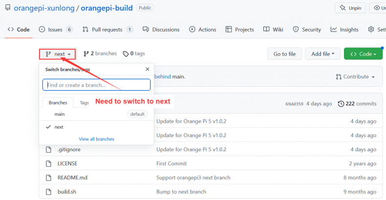

Downloading the orangepi-build code through the git clone command does not require entering the user name and password of the github account (the same is true for downloading other codes in this manual), if the Ubuntu PC prompts the user to enter the github account after entering the git clone command The name and password are usually entered incorrectly in the address of the orangepi-build warehouse behind the git clone. Please check the spelling of the command carefully, instead of thinking that we forgot to provide the username and password of the github account.
- The u-boot and Linux kernel versions currently used by the development board are as follows
| branch | u-boot version | Linux Kernel version |
| legacy | u-boot 2017.09 | Linux5.10 |
|
The branch mentioned here is not the same thing as the branch of the orangepi-build source code, please do not confuse it. This branch is mainly used to distinguish different kernel source code versions. Currently, the Linux5.10 bsp kernel provided by RK is defined as the legacy branch. If the mainline kernel is supported in the future, a current branch will be added. |
orangepi-build will contain the following files and folders after downloading
build.sh: Compile the startup script
external: Contains the configuration files needed to compile the image, specific scripts, and the source code of some programs, etc.
LICENSE: GPL 2 license file
README.md: orangepi-build documentation
scripts: General script for compiling Linux images
test@test:~/orangepi-build$ ls
build.sh external LICENSE README.md scripts
If you downloaded the code of orangepi-build from github, after downloading, you may find that orangepi-build does not contain the source code of u-boot and Linux kernel, nor does u-boot and Linux kernel need to use cross-compilation tools Chain, this is normal, because these things are stored in other separate github warehouses or some servers (the addresses will be detailed below). orangepi-build will specify the address of u-boot, Linux kernel and cross-compilation toolchain in the script and configuration file. When running orangepi-build, when it finds that there are no such things locally, it will automatically go to the corresponding place to download them.
Download the cross-compilation toolchain
|
The cross-compilation toolchain will only be downloaded when the orangepi-build compilation image is used on an x64 computer. Compiling the Linux image of the development board in the Ubuntu22.04 of the development board will not download the cross-compilation toolchain. At this time, orangepi-build/toolchains will be an empty folder. |
- When orangepi-build runs for the first time, it will automatically download the cross-compilation toolchain and put it in the toolchains folder. Every time after running the build.sh script of orangepi-build, it will check whether the cross-compilation toolchain in toolchains exists , if it does not exist, the download will be restarted, if it exists, it will be used directly, and the download will not be repeated.

- The image URL of the cross-compilation toolchain in China is the open source software image site of Tsinghua University
|
https://mirrors.tuna.tsinghua.edu.cn/armbian-releases/_toolchain/ |
- After toolchains is downloaded, it will contain multiple versions of cross-compilation toolchains, and the development board will only use two of them
|
test@test:~/orangepi-build$ ls toolchains/ gcc-arm-11.2-2022.02-x86_64-aarch64-none-linux-gnu gcc-arm-11.2-2022.02-x86_64-arm-none-linux-gnueabihf gcc-arm-9.2-2019.12-x86_64-aarch64-none-linux-gnu gcc-arm-9.2-2019.12-x86_64-arm-none-linux-gnueabihf gcc-linaro-4.9.4-2017.01-x86_64_arm-linux-gnueabi gcc-linaro-5.5.0-2017.10-x86_64_arm-linux-gnueabihf gcc-linaro-7.4.1-2019.02-x86_64_aarch64-linux-gnu gcc-linaro-7.4.1-2019.02-x86_64_arm-linux-gnueabi gcc-linaro-aarch64-none-elf-4.8-2013.11_linux gcc-linaro-arm-linux-gnueabihf-4.8-2014.04_linux gcc-linaro-arm-none-eabi-4.8-2014.04_linux |
The cross-compilation toolchain used to compile the Linux kernel source code is
- Linux5.10
gcc-arm-11.2-2022.02-x86_64-aarch64-none-linux-gnu
The cross-compilation tool chain used to compile the u-boot source code is
- v2017.09
gcc-linaro-7.4.1-2019.02-x86_64_aarch64-linux-gnu
orangepi-build complete directory structure description
The orangepi-build repository does not contain the source code of the Linux kernel, u-boot, and cross-compilation toolchain after downloading. The source code of the Linux kernel and u-boot is stored in an independent git repository
- The git repository where the Linux kernel source code is stored is as follows:
root@orangepi:~# cd /sys/class/leds/status_led
https://github.com/orangepi-xunlong/linux-orangepi/tree/orange-pi-5.10-rk35xx
- The git warehouse where the b.u-boot source code is stored is as follows:
root@orangepi:~# cd /sys/class/leds/status_led
https://github.com/orangepi-xunlong/u-boot-orangepi/tree/v2017.09-rk3588
When orangepi-build runs for the first time, it will download the cross-compilation toolchain, u-boot and Linux kernel source code. After successfully compiling a Linux image, the files and folders that can be seen in orangepi-build are:
a. build.sh: compile startup script
b. external: Contains the configuration files needed to compile the image, scripts with specific functions, and the source code of some programs. The rootfs compressed package cached during the image compilation process is also stored in external
c. kernel: stores the source code of the Linux kernel, and the folder named orange-pi-5.10-rk35xx stores the kernel source code of the legacy branch of the RK3588/RK3588S/RK3566 series development boards. Please do not manually name the folder name of the kernel source code Modify, if modified, the kernel source code will be re-downloaded when the compilation system is running
d. LICENSE: GPL 2 license file
e. README.md: orangepi-build documentation
f. output: Store compiled deb packages such as u-boot and Linux, compilation logs, and compiled images and other files
g. scripts: general scripts for compiling Linux images
h. toolchains: store cross-compilation toolchain
i. u-boot: stores the source code of u-boot, the folder named v2017.09-rk3588 stores the u-boot source code of the legacy branch of the RK3588/RK3588S/RK3566 series development boards, the name of the folder of the u-boot source code Please do not modify it manually, if it is modified, the u-boot source code will be re-downloaded when the compiling system is running
j. userpatches: Store configuration files needed to compile scripts
test@test:~/orangepi-build$ ls
build.sh external kernel LICENSE output README.md scripts toolchains u-boot userpatches
Compile u-boot
- Run the build.sh script, remember to add sudo permission
test@test:~/orangepi-build$ sudo ./build.sh
Select U-boot package, then enter
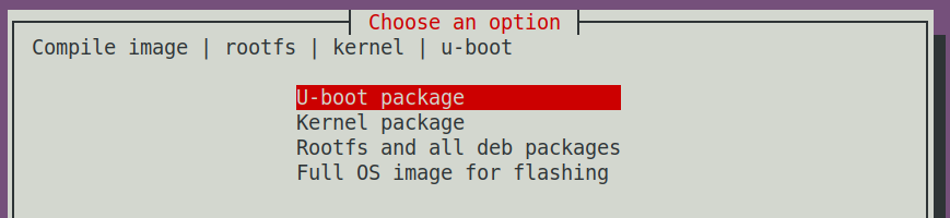
Then select the model of the development board
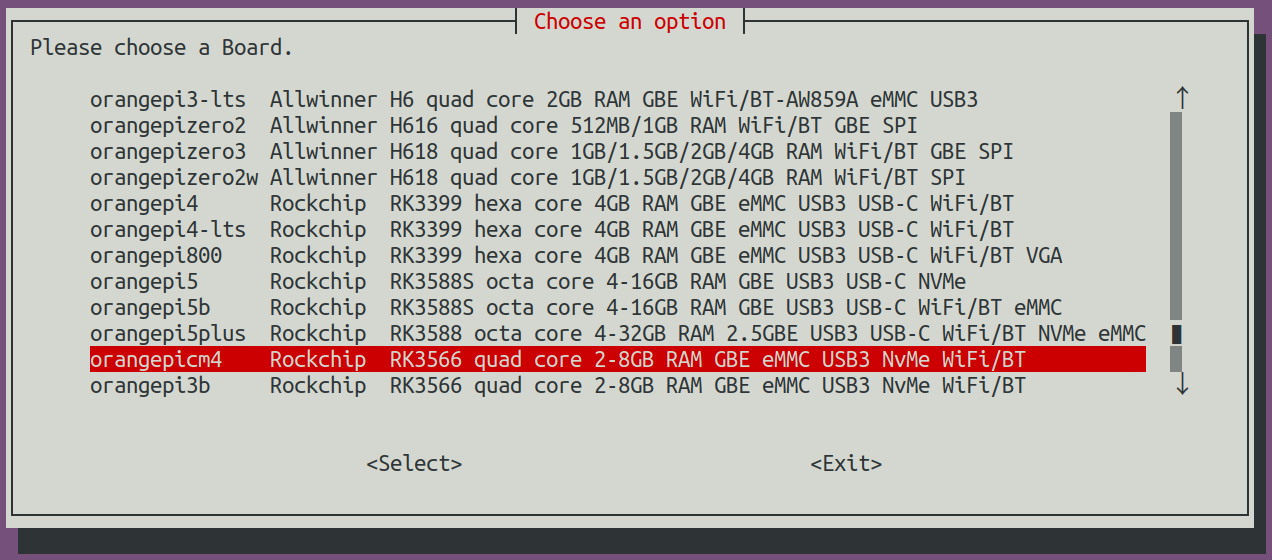
Then it will start to compile u-boot, and some information prompted during compilation is explained as follows
- u-boot source code version
[ o.k. ] Compiling u-boot [ v2017.09 ]
- The version of the cross-compilation toolchain
[ o.k. ] Compiler version [ aarch64-linux-gnu-gcc 7.4.1 ]
- Path to the generated u-boot deb package
[ o.k. ] Target directory [ orangepi-build/output/debs/u-boot ]
- The package name of the generated u-boot deb package
[ o.k. ] File name [ linux-u-boot-legacy-orangepi3b_1.0.0_arm64.deb ]
- Compilation time
[ o.k. ] Runtime [ 1 min ]
- Repeat the command to compile u-boot, use the following command to start compiling u-boot directly without selecting through the graphical interface
[ o.k. ] Repeat Build Options [ sudo ./build.sh BOARD=orangepi3b BRANCH=legacy BUILD_OPT=u-boot KERNEL_CONFIGURE=no ]

- View the u-boot deb package generated by compilation
|
test@test:~/orangepi-build$ ls output/debs/u-boot/ linux-u-boot-legacy-orangepi3b_1.0.0_arm64.deb |
The files contained in the generated u-boot deb package are as follows
- Use the following command to decompress the deb package
test@test:~/orangepi-build$ cd output/debs/u-boot
test@test:~/orangepi_build/output/debs/u-boot$ $ dpkg -x \
linux-u-boot-legacy-orangepi3b_1.0.0_arm64.deb . (Note that there is a "." at the end of the command)
test@test:~/orangepi_build/output/debs/u-boot$ ls
linux-u-boot-legacy-orangepi3b_1.0.0_arm64.deb usr
- The decompressed file is as follows
- ├── linux-u-boot-legacy-orangepi3b_1.0.0_arm64
- │ ├── idbloader.img
- │ ├── rkspi_loader.img
- │ └── u-boot.itb
- └── u-boot
- ├── LICENSE
- ├── orangepi-3b-rk3566_defconfig
- └── platform_install.sh
test@test:~/orangepi-build/output/debs/u-boot$ tree usr
usr
└── lib
3 directories, 6 files
- When the orangepi-bulid compilation system compiles the u-boot source code, it will first synchronize the u-boot source code with the u-boot source code of the github server, so if you want to modify the u-boot source code, you first need to turn off the download and update function of the source code (This function needs to be fully compiled once u-boot, otherwise it will prompt that the source code of u-boot cannot be found. If the source code package downloaded from Baidu cloud disk, there is no such problem, because the source code of u-boot is all cached), otherwise the changes made will be reverted, the method is as follows:
Set the IGNORE_UPDATES variable in userpatches/config-default.conf to "yes"
|
test@test:~/orangepi-build$ vim userpatches/config-default.conf IGNORE_UPDATES="yes" |
When debugging u-boot code, you can use the following method to update u-boot in the Linux image for testing
- Upload the compiled u-boot deb package to the Linux system of the development board
test@test:~/orangepi-build$ cd output/debs/u-boot
test@test:~/orangepi_build/output/debs/u-boot$ scp \
linux-u-boot-legacy-orangepi3b_1.0.0_arm64.deb root@192.168.1.xxx:/root
- Then log in to the development board and uninstall the deb package of u-boot installed
root@orangepi:~# apt purge -y linux-u-boot-orangepi3b-legacy
- Install the new u-boot deb package just uploaded
root@orangepi:~# dpkg -i linux-u-boot-legacy-orangepi3b_1.0.0_arm64.deb
- Then run the nand-sata-install script
root@orangepi:~# nand-sata-install
- Then select 5 Install/Update the bootloader on SD/eMMC to update the u-boot in the TF card or 7 Install/Update the bootloader on SPI Flash to update the u-boot in the SPI Flash
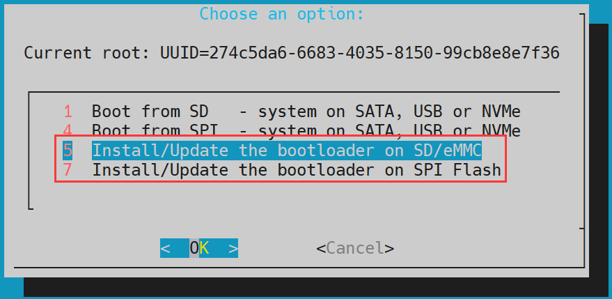
- After pressing the Enter key, a Warning will pop up first
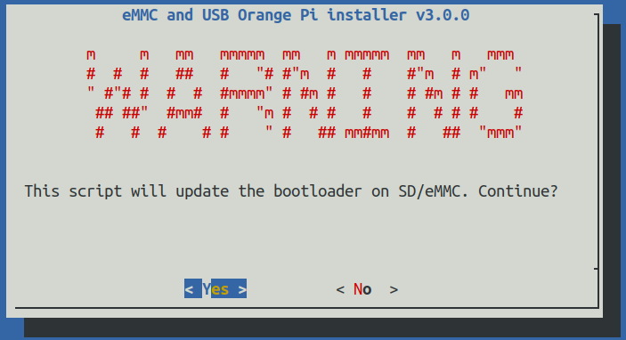
- Press the Enter key again to start updating u-boot, and the following information will be displayed after the update is completed
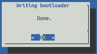
- Then you can restart the development board to test whether the modification of u-boot takes effect


Other useful information
- In the u-boot 2017.09 source code, the defconfig configuration file used by the development board is
orangepi-build/u-boot/v2017.09-rk3588/configs/orangepi-3b-rk3566_defconfig
- In the u-boot 2017.09 source code, the dts file used by the development board is
orangepi-build/u-boot/v2017.09-rk3588/arch/arm/dts/rk3566-orangepi-3b.dts
Compile the Linux kernel
- Run the build.sh script, remember to add sudo permission
test@test:~/orangepi-build$ sudo ./build.sh
- Select Kernel package, then enter

- Then select the model of the development board

- Then it will prompt whether to display the kernel configuration interface. If you do not need to modify the kernel configuration, select the first one. If you need to modify the kernel configuration, select the second one.

- If you choose to display the kernel configuration menu (the second option) in step 4, the kernel configuration interface opened by make menuconfig will pop up. At this time, you can directly modify the kernel configuration, save and exit after modification. Yes, after exiting, the kernel source code will be compiled
- If you do not need to modify the configuration options of the kernel, when running the build.sh script, pass in KERNEL_CONFIGURE=no to temporarily block the pop-up kernel configuration interface
You can also set KERNEL_CONFIGURE=no in the orangepi-build/userpatches/config-default.conf configuration file, which can permanently disable this function
If the following error is displayed when compiling the kernel, it is because the terminal interface of the Ubuntu PC is too small to display the make menuconfig interface. Please maximize the terminal of the Ubuntu PC and run the build.sh script again

|
test@test:~/orangepi-build$ sudo ./build.sh KERNEL_CONFIGURE=no |

Part of the information prompted when compiling the kernel source code is as follows
- The version of the Linux kernel source code
[ o.k. ] Compiling current kernel [ 5.10.160 ]
- The version of the cross-compilation toolchain used
[ o.k. ] Compiler version [ aarch64-none-linux-gnu-gcc 11.2.1 ]
- The configuration file used by the kernel by default and the path where it is stored
[ o.k. ] Using kernel config file [ config/kernel/linux-rockchip-rk356x-legacy.config ]
- The path of the deb package related to the kernel generated by compiling
[ o.k. ] Target directory [ orangepi-build/output/debs/ ]
- The package name of the compiled kernel image deb package
[ o.k. ] File name [ linux-image-legacy-rockchip-rk356x_1.0.0_arm64.deb ]
- The time used for compilation
[ o.k. ] Runtime [ 5 min ]
- Finally, the compilation command to repeatedly compile the kernel selected last time will be displayed. Use the following command to start compiling the kernel source code directly without selecting through the graphical interface
[ o.k. ] Repeat Build Options [ sudo ./build.sh BOARD=orangepi3b BRANCH=legacy BUILD_OPT=kernel KERNEL_CONFIGURE=no ]
View the deb package related to the kernel generated by compilation
linux-dtb-legacy-rockchip-rk356x_1.0.0_arm64.deb Contains dtb files used by the kernel
linux-headers-legacy-rockchip-rk356x_1.0.0_arm64.deb Include kernel header files
linux-image-legacy-rockchip-rk356x_1.0.0_arm64.deb Contains kernel images and kernel modules
test@test:~/orangepi-build$ ls output/debs/linux-*
output/debs/linux-dtb-legacy-rockchip-rk356x_1.0.0_arm64.deb output/debs/linux-image-legacy-rockchip-rk356x_1.0.0_arm64.deb
output/debs/linux-headers-legacy-rockchip-rk356x_1.0.0_arm64.deb
The files contained in the generated Linux-image deb package are as follows
- Use the following command to decompress the deb package
test@test:~/orangepi-build$ cd output/debs
test@test:~/orangepi_build/output/debs$ mkdir test
test@test:~/orangepi_build/output/debs$ cp \
linux-image-legacy-rockchip-rk356x_1.0.0_arm64.deb test/
test@test:~/orangepi_build/output/debs$ cd test
test@test:~/orangepi_build/output/debs/test$ dpkg -x \
linux-image-legacy-rockchip-rk356x_1.0.0_arm64.deb .
test@test:~/orangepi_build/output/debs/test$ ls
boot etc lib linux-image-legacy-rockchip-rk356x_1.0.0_arm64.deb usr
- The decompressed file is as follows
- ├── lib
- └── share
test@test:~/orangepi-build/output/debs/test$ tree -L 2
.
├── boot
│ ├── config-5.10.160-rockchip-rk356x
│ ├── System.map-5.10.160-rockchip-rk356x
│ └── vmlinuz-5.10.160-rockchip-rk356x
├── etc
│ └── kernel
├── lib
│ └── modules
├── linux-image-legacy-rockchip-rk356x_1.0.0_arm64.deb
└── usr
- The orangepi-bulid compilation system will first synchronize the Linux kernel source code with the Linux kernel source code of the github server when compiling the Linux kernel source code, so if you want to modify the Linux kernel source code, you first need to turn off the update function of the source code (You need to fully compile the Linux kernel source code before turning off this function. Otherwise, you will be prompted that the source code of the Linux kernel cannot be found. If you download the source code package from Baidu cloud disk, there is no such problem, because the source code of Linux has been cached.), otherwise the The changes made will be reverted as follows:
Set the IGNORE_UPDATES variable in userpatches/config-default.conf to "yes"
|
test@test:~/orangepi-build$ vim userpatches/config-default.conf IGNORE_UPDATES="yes" |
If the kernel has been modified, the following method can be used to update the kernel and kernel modules of the development board Linux system
- Upload the deb package of the compiled Linux kernel to the Linux system of the development board
test@test:~/orangepi-build$ cd output/debs
test@test:~/orangepi-build/output/debs$ scp \
linux-image-legacy-rockchip-rk356x_1.0.0_arm64.deb root@192.168.1.xxx:/root
- Then log in to the development board and uninstall the deb package of the installed Linux kernel
root@orangepi:~# apt purge -y linux-image-legacy-rockchip-rk356x
- Install the deb package of the new Linux kernel just uploaded
root@orangepi:~# dpkg -i linux-image-legacy-rockchip-rk356x_1.0.0_arm64.deb
- Then restart the development board, and then check whether the kernel-related modifications have taken effect
root@orangepi:~# reboot
Other useful information
The storage location of the kernel configuration file is as follows, please do not go to the kernel source code to find the kernel configuration file used by the development board
The location of the dts file used by the development board is
orangepi-build/external/config/kernel/linux-rockchip-rk356x-legacy.config
orangepi-build/kernel/orange-pi-5.10-rk35xx/arch/arm64/boot/dts/rockchip/rk3566-orangepi-cm4.dts
Compile rootfs
- Run the build.sh script, remember to add sudo permission
test@test:~/orangepi-build$ sudo ./build.sh
- Select Rootfs and all deb packages, then enter

- Then select the model of the development board
- Then select the type of rootfs

Then select the type of image
Image with console interface (server) Indicates the image of the server version, which is relatively small
Image with desktop environment Indicates a image with a desktop, which is relatively large
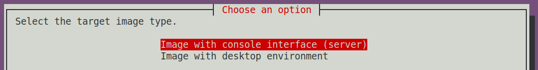

- If you are compiling the image of the server version, you can also choose to compile the Standard version or the Minimal version. The pre-installed software of the Minimal version will be much less than that of the Standard version (please do not choose the Minimal version if there is no special requirement, because many things are not pre-installed by default. Some functions may not be available)

- If you are compiling the image of the desktop version, you also need to select the type of desktop environment. Currently, Ubuntu Jammy mainly maintains XFCE and Gnome desktops, Ubuntu Focal only maintains XFCE desktops, and Debian Bullseye mainly maintains XFCE and KDE desktops


You can then select additional packages that need to be installed. Please press the Enter key to skip directly here.

Then it will start to compile rootfs, and some of the information prompted during compilation are as follows
- The type of rootfs
[ o.k. ] local not found [ Creating new rootfs cache for jammy]
- The storage path of the compiled rootfs compressed package
[ o.k. ] Target directory [ external/cache/rootfs ]
- The name of the rootfs compressed package generated by compilation
[ o.k. ] File name [ jammy-xfce-arm64.f930ff6ebbac1a72108a2e100762b18f.tar.lz4 ]
- The time used for compilation
[ o.k. ] Runtime [ 13 min ]
View the rootfs compressed package generated by compilation
jammy-xfce-arm64.f930ff6ebbac1a72108a2e100762b18f.tar.lz4 is the rootfs compressed package, the meaning of each field of the name is
a) jammy indicates the type of Linux distribution of rootfs
b) xfce means rootfs is the type of desktop version, if it is cli, it means the type of server version
c) arm64 represents the architecture type of rootfs
d) f930ff6ebbac1a72108a2e100762b18f is the MD5 hash value generated by the package names of all software packages installed by rootfs. As long as the list of software packages installed by rootfs is not modified, this value will not change. The compilation script will use this MD5 hash value to generate Determine whether rootfs needs to be recompiled
jammy-xfce-arm64.f930ff6ebbac1a72108a2e100762b18f.tar.lz4.list lists the package names of all packages installed by rootfs
test@test:~/orangepi-build$ ls external/cache/rootfs/
jammy-xfce-arm64.f930ff6ebbac1a72108a2e100762b18f.tar.lz4
jammy-xfce-arm64.f930ff6ebbac1a72108a2e100762b18f.tar.lz4.current
jammy-xfce-arm64.f930ff6ebbac1a72108a2e100762b18f.tar.lz4.list
- If the required rootfs already exists under external/cache/rootfs, then compiling rootfs again will directly skip the compilation process and will not restart the compilation. When compiling the image, it will also go to external/cache/rootfs to find out whether it has If there is rootfs available in the cache, use it directly, which can save a lot of download and compilation time.
Compile Linux image
- Run the build.sh script, remember to add sudo permission
test@test:~/orangepi-build$ sudo ./build.sh
- Select Full OS image for flashing, then enter

- Then select the model of the development board
- Then select the type of rootfs
Then select the type of image
Image with console interface (server) Indicates the image of the server version, which is relatively small
Image with desktop environment Indicates a image with a desktop, which is relatively large
- If you are compiling the image of the server version, you can also choose to compile the Standard version or the Minimal version. The pre-installed software of the Minimal version will be much less than that of the Standard version (please do not choose the Minimal version if there is no special requirement, because many things are not pre-installed by default. Some functions may not be available)
- If you are compiling the image of the desktop version, you also need to select the type of desktop environment. Currently, Ubuntu Jammy mainly maintains XFCE and Gnome desktops, Ubuntu Focal only maintains XFCE desktops, and Debian Bullseye mainly maintains XFCE and KDE desktops
You can then select additional packages that need to be installed. Please press the Enter key to skip directly here.
Then it will start to compile the Linux image. The general process of compilation is as follows
a. Initialize the compilation environment of Ubuntu PC and install the software packages required for the compilation process
b. Download the source code of u-boot and Linux kernel (if cached, only update the code)
c. Compile u-boot source code and generate u-boot deb package
d. Compile the Linux source code and generate Linux-related deb packages
e. Make the deb package of Linux firmware
f. Make the deb package of the orangepi-config tool
g. Create a deb package supported by the board
h. If you are compiling the desktop image, you will also create desktop-related deb packages
i. Check whether the rootfs has been cached, if not, recreate the rootfs, if it has been cached, directly decompress and use
j. Install the previously generated deb package into rootfs
k. Make some specific settings for different development boards and different types of images, such as pre-installing additional software packages, modifying system configuration, etc.
l. Then make an image file and format the partition, the default type is ext4
m. Then copy the configured rootfs to the mirrored partition
n. Then update initramfs
o. Finally, write the bin file of u-boot into the image through the dd command
After compiling the image, the following information will be prompted
- The storage path of the compiled image
[ o.k. ] Done building [ output/images/Orangepi3b_1.0.0_debian_bullseye_desktop_xfce_linux5.10.160/Orangepi3b_1.0.0_debian_bullseye_desktop_xfce_linux5.10.160.img ]
- Compilation time
[ o.k. ] Runtime [ 19 min ]
- Repeat the command to compile the image, and use the following command to start compiling the image directly without selecting through the graphical interface
[ o.k. ] Repeat Build Options [ sudo ./build.sh BOARD=orangepi3b BRANCH=legacy BUILD_OPT=image RELEASE=bullseye BUILD_MINIMAL=no BUILD_DESKTOP=no KERNEL_CONFIGURE=yes ]
Instructions for using the Orange Pi OS Arch system
Orange Pi OS Arch system function adaptation
| Function | OPi OS Arch |
| USB2.0x3 | OK |
| USB3.0x1 | OK |
| SPIFlash+M.2 NVMe SSD Boot | OK, It needs to be pasted with SPI Flash to work normally |
| WIFI | OK |
| Bluetooth | OK |
| GPIO(40pin) | OK |
| UART(40pin) | OK |
| SPI(40pin) | OK |
| I2C(40pin) | OK |
| PWM(40pin) | OK |
| 3pin debugging serial port | OK |
| eMMC start | OK |
| TF card start | OK |
| HDMI video | OK |
| HDMI audio | OK |
| Raspberry Pi 5 inch screen display | OK |
| Raspberry Pi 5-inch screen touch function | OK |
| eDP display | OK |
| OV5647 camera | The kernel driver is OK, 3A is not adjusted |
| Gigabit Ethernet port | OK |
| Network port status light | OK |
| headphone playback | OK |
| headphone recording | OK |
| LED lights | OK |
| GPU | NO |
| NPU | NO |
| VPU | NO |
Orange Pi OS Arch System User Guide Instructions
First of all, please note that the OPi OS Arch system does not have a default orangepi user and password, so after burning and starting the system, it is impossible to log in remotely through the serial port and ssh directly (not even the root user). This is different from Ubuntu and Debian systems.
When the OPi OS Arch system starts for the first time, it needs to be connected to an HDMI display, and then initialize the system settings through the user wizard (including creating a new user name and setting a password). The setup steps of the User Wizard are as follows:
After burning the system, you will see the user wizard program shown in the figure below after starting the system for the first time and entering the desktop
First you need to choose the desired language
After selecting the language, the user guide will immediately switch to the corresponding language interface, such as the Chinese display as shown below
Then select the area
Then select the keyboard model
Then create a new user name and set a password
Then make sure that there is no problem with the selection, and then click the install button
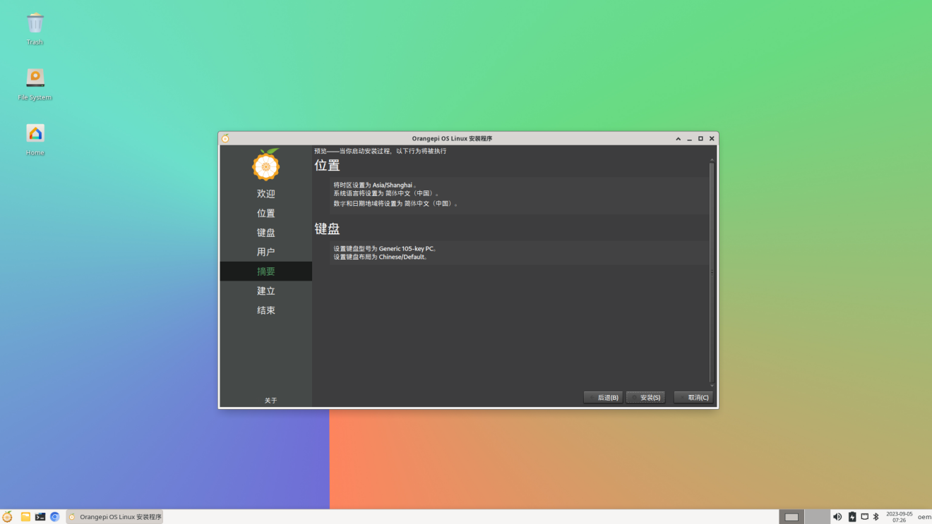
Then wait for the installation to complete
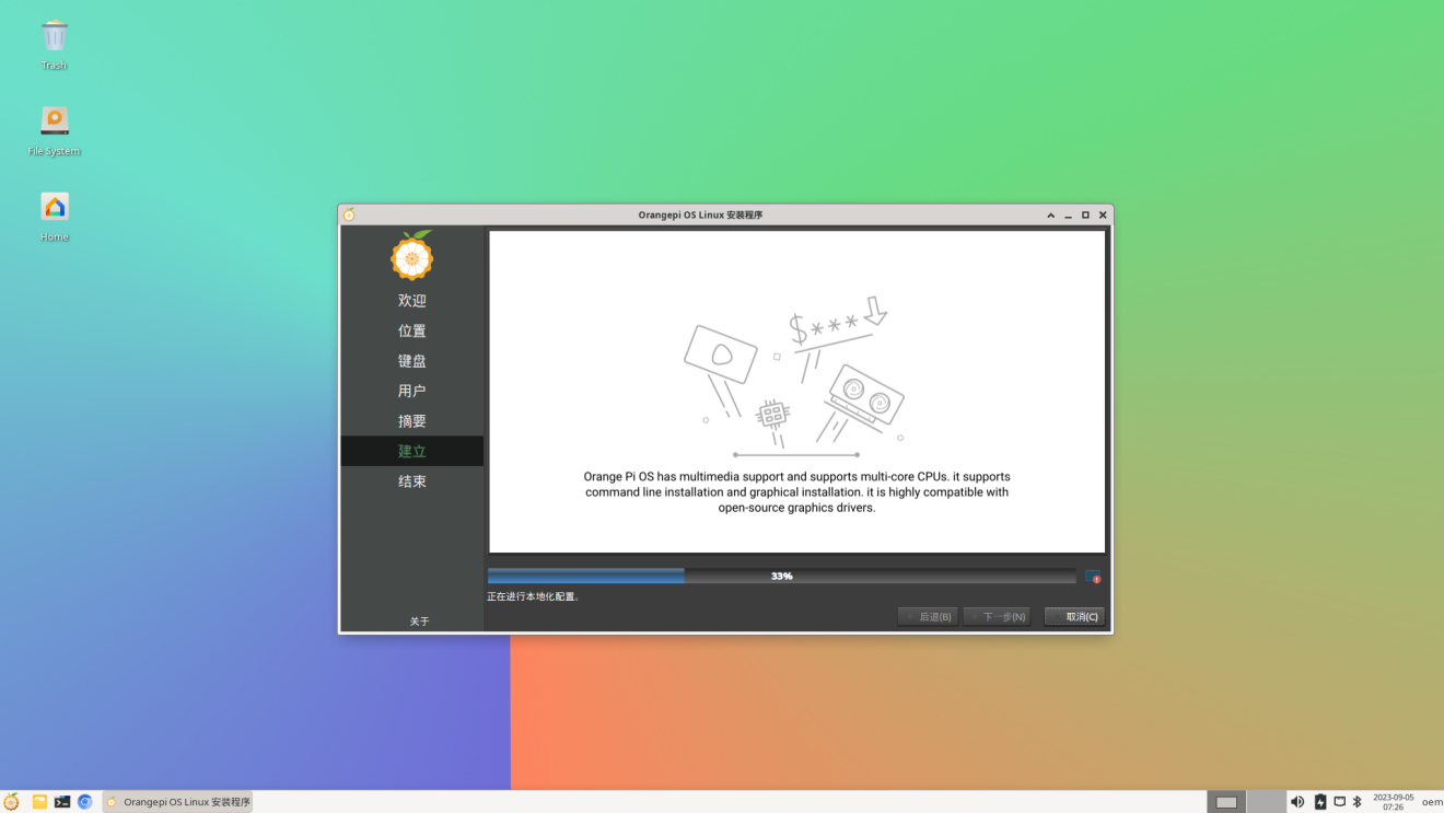
After the installation is complete, you need to click the Finish button to restart the system
After restarting, the Orange Pi Hello program will be started automatically. At this time, you need to remove the check status in the lower right corner when starting up. Otherwise, you need to manually close the Orange Pi Hello program every time you start it.
At this point, you can use the newly created user name and password to log in to the OPi OS system through the serial port or ssh.


How to set DT overlays
LCD MIPI screen, eDP screen, and multiplexing functions such as I2C/SPI/UART/PWM in 40pin are disabled by default in the dts of the kernel, and the corresponding DT overlays need to be manually enabled to use.
The method of opening DT overlays in OPi OS Arch system is as follows:
First open the /boot/extlinux/extlinux.conf configuration file
[orangepi@orangepi-pc ~]$ sudo vim /boot/extlinux/extlinux.conf
Then open the corresponding configuration by adding FDTOVERLAYS /dtbs/rockchip/overlay/xxx.dtbo in /boot/extlinux/extlinux.conf
|
Note that xxx.dtbo in FDTOVERLAYS /dtbs/rockchip/overlay/xxx.dtbo needs to be replaced with the specific dtbo configuration, please do not copy it. |
|
[orangepi@orangepi-pc ~]$ sudo vim /boot/extlinux/extlinux.conf LABEL OPIOS ARM LINUX /Image FDT /dtbs/rockchip/rk3566-orangepi-3b.dtb FDTOVERLAYS /dtbs/rockchip/overlay/xxx.dtbo #Configuration that needs to be added |
The storage path of xxx.dtbo in the OPi OS Arch image is as follows, please note that not all dtbos under this path can be used.
/boot/dtbs/rockchip/overlay/
The DT overlays configuration that can be used by the development board is as follows
| Features on the development board | Corresponding DT overlays configuration |
| EDP screen | rk356x-edp.dtbo |
| Raspberry Pi 5 inch screen | rk356x-raspi-7inch-touchscreen.dtbo |
| 40pin expansion interface - I2C2 | rk356x-i2c2-m1.dtbo |
| 40pin expansion interface - I2C3 | rk356x-i2c3-m0.dtbo |
| 40pin expansion interface - I2C4 | rk356x-i2c4-m0.dtbo |
| 40pin extension interface - PWM11 | rk356x-pwm11-m1.dtbo |
| 40pin extension interface - PWM15 | rk356x-pwm15-m1.dtbo |
| 40pin expansion interface - UART3 | rk356x-uart3-m0.dtbo |
| 40pin expansion interface - UART7 | rk356x-uart7-m2.dtbo |
| 40pin expansion interface - UART9 | rk356x-uart9-m2.dtbo |
| 40pin expansion interface - SPI3 | rk356x-spi3-m0-cs0-spidev.dtbo |
If you need to open multiple configurations at the same time, just add the paths of multiple configurations directly behind FDTOVERLAYS. For example, the configurations to open i2c2 and pwm11 at the same time are as follows
[orangepi@orangepi-pc ~]$ sudo vim /boot/extlinux/extlinux.conf
LABEL OPIOS ARM
LINUX /Image
FDT /dtbs/rockchip/rk3566-orangepi-3b.dtb
FDTOVERLAYS /dtbs/rockchip/overlay/rk356x-i2c2-m1.dtbo /dtbs/rockchip/overlay/rk356x-pwm11-m1.dtbo
After setting, you need to restart the system to make the configuration take effect
[orangepi@orangepi-pc ~]$ sudo reboot
Use of Raspberry Pi 5-inch screen
How to assemble the Raspberry Pi 5-inch screen
Please refer to the assembly method of the Raspberry Pi 5-inch screen (click the text in the blue part to jump to the corresponding position).
How to open Raspberry Pi 5-inch screen configuration
By default, OPi OS Arch mirroring does not enable the configuration of the Raspberry Pi 5-inch screen. If you need to use the Raspberry Pi 5-inch screen, you need to manually open it. The method to open the configuration is as follows:
First add the following configuration in /boot/extlinux/extlinux.conf
[orangepi@orangepi-pc ~]$ sudo vim /boot/extlinux/extlinux.conf
LABEL OPIOS ARM
LINUX /Image
FDT /dtbs/rockchip/rk3566-orangepi-3b.dtb
FDTOVERLAYS /dtbs/rockchip/overlay/rk356x-raspi-7inch-touchscreen.dtbo #Configuration that needs to be added
Then restart the system
[orangepi@orangepi-pc ~]$ sudo reboot
After restarting, you can see the display on the LCD screen as follows:

How to use the eDP screen
Assembly method of eDP screen
Please refer to how to use the eDP screen (click the text in the blue part to jump to the corresponding position).
How to open eDP screen configuration
The OPi OS Arch image does not enable the eDP screen configuration by default. If you want to use the eDP screen, you need to manually open it. The method to open the configuration is as follows:
First add the following configuration in /boot/extlinux/extlinux.conf
[orangepi@orangepi-pc ~]$ sudo vim /boot/extlinux/extlinux.conf
LABEL OPIOS ARM
LINUX /Image
FDT /dtbs/rockchip/rk3566-orangepi-3b.dtb
FDTOVERLAYS /dtbs/rockchip/overlay/rk356x-edp.dtbo #Configuration that needs to be added
Then restart the system
[orangepi@orangepi-pc ~]$ sudo reboot
After restarting, you can see that the display of the eDP screen is as follows:

How to install the software
Use the pacman package management tool to install software that is not in OPi OS. For example, the command to install the vim editor is as follows. If you want to install other software, you only need to replace vim with the package name of the software you want to install.
|
[orangepi@orangepi-pc ~]$ sudo pacman -Syy vim |
Android 11 operating system instructions
Supported Android versions
| Android version | Kernel version |
| Android 11 | Linux4.19 |
Android Function Adaptation
| Functions | Android 11 |
| USB2.0x3 | OK |
| USB3.0x1 | OK |
| M.2 NVMe SSD boot | OK |
| WIFI | OK |
| Bluetooth | OK |
| GPIO(40pin) | OK |
| UART(40pin) | OK |
| SPI(40pin) | OK |
| I2C(40pin) | OK |
| PWM(40pin) | OK |
| PWM fan interface | OK |
| 3pin Debugging serial port | OK |
| EMMC | OK |
| TF card boot | OK |
| HDMI video | OK |
| HDMI Audio | OK |
| LCD | OK |
| eDP display | OK |
| OV5647 Camera | The kernel driver is OK, 3A is not adjusted |
| Gigabit network port | OK |
| Network port status indicator | OK |
| Headphone playback | OK |
| Headphone recording | OK |
| LED Light | OK |
| GPU | OK |
| NPU | OK |
| VPU | OK |
| RTC | OK |
WIFI connection test method
- First click enter Setting

- Then select Network & internet

- Then select Wi-Fi

- Then turn on the Wi-Fi switch

- After turning on Wi-Fi, if everything is normal, you can scan for nearby Wi-Fi hotspots

- Then select the Wi-Fi you want to connect to, and the password input interface shown in the figure below will pop up

- Then use the keyboard to enter the password corresponding to Wi-Fi, and then use the mouse to click the Enter button in the virtual keyboard to start connecting to Wi-Fi

- After the Wi-Fi connection is successful, the display is as shown in the figure below:

How to use Wi-Fi hotspot
- First, please make sure that the Ethernet port is connected to the network cable and can access the Internet normally
- Then select Settings
- Then select Network & internet
- Then select Hotspot & tethering

- Then select Wi-Fi hotspot

- Then turn on the Wi-Fi hotspot, you can also see the name and password of the generated hotspot in the figure below, remember them, and use them when connecting to the hotspot (If you need to modify the name and password of the hotspot, you need to turn off the Wi-Fi hotspot first, and then you can modify it)

- At this time, you can take out your mobile phone. If everything is normal, you can find the WIFI hotspot with the same name (here AndroidAP_6953) displayed under the Hotspot name in the above picture in the WI-FI list searched by the mobile phone. Then you can click AndroidAP_6953 to connect to the hotspot, and the password can be seen under the Hotspot password in the above picture

- After the connection is successful, it will be displayed as shown in the figure below (the interface of different mobile phones will be different, the specific interface is subject to the display of your mobile phone). At this point, you can open a webpage on your mobile phone to see if you can access the Internet. If you can open the webpage normally, it means that the WI-FI Hotspot of the development board can be used normally.

Bluetooth test method
- First click enter Setting
- Then select Connected devices

- Then click Pair new device to turn on Bluetooth and start scanning the surrounding Bluetooth devices

- The searched Bluetooth devices will be displayed under Available devices

- Then click the Bluetooth device you want to connect to start pairing. When the following interface pops up, please use the mouse to select the Pair option

- The test here is the configuration process of the development board and the Bluetooth of the Android mobile phone. At this time, the following confirmation interface will pop up on the mobile phone. After clicking the pairing button on the mobile phone, the pairing process will start

- After the pairing is completed, you can see the paired Bluetooth device as shown in the figure below

- At this time, you can use the Bluetooth of your mobile phone to send a picture to the development board. After sending, you can see the following confirmation interface in the Android system of the development board, and then click Accept to start receiving the picture sent by the mobile phone.

- You can open the Download directory in the file manager to view the pictures received by the Android system Bluetooth of the development board

How to use Raspberry Pi 5-inch screen
|
Please make sure that the image used is the following two versions of the image: OrangePi3B_RK3566_Android11_lcd_v1.x.x.img OrangePi3B_RK3566_Android11_spi-nvme_lcd_v1.x.x.img |
The screen needs to be assembled first, please refer to the assembly method of the Raspberry Pi 5-inch screen
Connect the Type-C power supply to the board and power it on. After the system starts, you can see the screen display as shown in the figure below
Both the display and touch of the Raspberry Pi 5-inch screen can be used. If you have problems with the screen test, please make sure that the screen you purchased is exactly the same as the screen that the Orange Pi is compatible with.
The Orange Pi compatible screen is described in the assembly method of the Raspberry Pi 5-inch screen.

How to use the eDP screen
|
Please make sure that the image used is the following two versions of the image: OrangePi3B_RK3566_Android11_lcd_v1.x.x.img OrangePi3B_RK3566_Android11_spi-nvme_lcd_v1.x.x.img |
|
The eDP screen has no touch function. |
Currently only one eDP screen is compatible, including the following accessories:
0.5 pitch 30pin single-head cable in the same direction
15.6-inch eDP display with a resolution of 1920x1080
Connect the FPC end of the 30pin single-head codirectional cable to the eDP interface of the development board, and connect the other end to the eDP interface of the screen

Then connect the Type-C power supply to the board and power it on. After the system starts, you can see the screen display as shown in the figure below

40pin interface GPIO, UART, SPI and PWM test
40pin GPIO port test
- First click on the wiringOP icon to open the wiringOP APP
- The main interface of wiringOP APP is displayed as shown in the figure below, and then click the GPIO_TEST button to open the GPIO test interface

- The GPIO test interface is shown in the figure below. The two rows of CheckBox buttons on the left are in one-to-one correspondence with the 40pin pins. When the CheckBox button is checked, the corresponding GPIO pin will be set to OUT mode, and the pin level will be set to high level; when the checkbox is unchecked, the GPIO pin level will be set to low level; When the GPIO READALL button is pressed, information such as wPi number, GPIO mode, and pin level can be obtained; when the BLINK ALL GPIO button is clicked, the program will control the 28 GPIO ports to continuously switch between high and low levels

- Then click the GPIO READALL button, the output information is as shown in the figure below:

- There are a total of 28 GPIO ports in the 40pins of the development board that can be used. The following uses pin 7—the corresponding GPIO is GPIO4_A4—the corresponding wPi serial number is 2—as an example to demonstrate how to set the high and low levels of the GPIO port. First click the CheckBox button corresponding to pin 7. When the button is selected, pin 7 will be set to high level. After setting, you can use a multimeter to measure the voltage value of the pin. If it is 3.3v, it means setting high level success

- Then click the GPIO READALL button, you can see that the current pin 7 mode is OUT, and the pin level is high

- Click the CheckBox button in the figure below again to cancel the check status. Pin 7 will be set to low level. After setting, you can use a multimeter to measure the voltage value of the pin. If it is 0v, it means that the low level is set successfully.

Then click the GPIO READALL button, you can see that the current pin 7 mode is OUT, and the pin level is low

40pin UART test
UART7 and UART9 are enabled by default in Android. The position of the 40pin is shown in the figure below, and the corresponding device nodes are /dev/ttyS7 and /dev/ttyS9 respectively
First click on the wiringOP icon to open the wiringOP APP


- The main interface of wiringOP APP is displayed as shown in the figure below, and then click the UART_TEST button to open the UART test interface

- The serial port test interface of the APP is shown in the figure below

- Take the test of UART7 as an example below, select the /dev/ttyS7 node in the selection box, enter the baud rate you want to set in the edit box, and then click the OPEN button to open the /dev/ttyS7 node. After the opening is successful, the OPEN button becomes unselectable, and the CLOSE button and SEND button become selectable

- Then use Dupont wire to short the RXD and TXD pins of uart7

- Then you can enter a character in the send edit box below, and click the SEND button to start sending

- If everything is normal, the received string will be displayed in the receiving box

40pin SPI test
- According to the schematic diagram of the 40pin interface, the spi available for Orange Pi 3B is spi3

- Here, the SPI interface is tested through the w25q64 module. First, the w25q64 device is connected to the SPI3 interface

- Then click the wiringOP icon to open the wiringOP APP
- The main interface of wiringOP APP is displayed as shown in the figure below, click the SPI_TEST button to open the SPI test interface

- Then click the OPEN button to initialize the SPI

- Then fill in the bytes that need to be sent, such as reading the ID information of w25q64, fill in the address 0x9f in data[0], and then click the TRANSFER button

- Finally, the APP will display the read ID information

- The MANUFACTURER ID of the w25q64 module is EFh, and the Device ID is 4017h, corresponding to the value read above (h stands for hexadecimal)

40pin PWM test
- Android enables PWM11 by default, and the corresponding pin is located at 40pin as shown in the figure below

- First click on the wiringOP icon to open the wiringOP APP
- Then click the PWM_TEST button on the main interface of wiringOP to enter the PWM test interface

- The base address corresponding to PWM11 is fe6f0030, here pwmchip0 shows fdd70020.pwm on the right, then you need to click the drop-down option to select other pwmchips until fe6f0030.pwm is displayed on the right

- When the drop-down option selects pwmchip3, the corresponding base address of PWM11 is fe6f0030 on the right

- Then confirm the PWM channel, the default is channel 0, and confirm the PWM cycle, the default configuration is 50000ns, converted to PWM frequency is 20KHz, you can modify it yourself, click the EXPORT button to export PWM11

- Then drag the drag bar below to change the PWM duty cycle, and then check Enable to output the PWM waveform

- Then use an oscilloscope to measure the No. 32 pin in the 40pin of the development board, and you can see the following waveform

How to use ADB
The method of USB OTG mode switching
|
The development board has 4 USB interfaces, among which the USB interface marked in red box in the figure below can support both Host mode and Device mode, and the other 3 USB interfaces only support Host mode.  The USB OTG interface defaults to Host mode, which can be used to connect USB devices such as mouse and keyboard. If you want to use ADB, you need to manually switch to Device mode. |
First open Settings

Then select About tablet
Then click the Build number menu bar several times with the mouse until the prompt You are now a developer! appears
Then click to return to the previous menu
Then select System
Then select Advanced
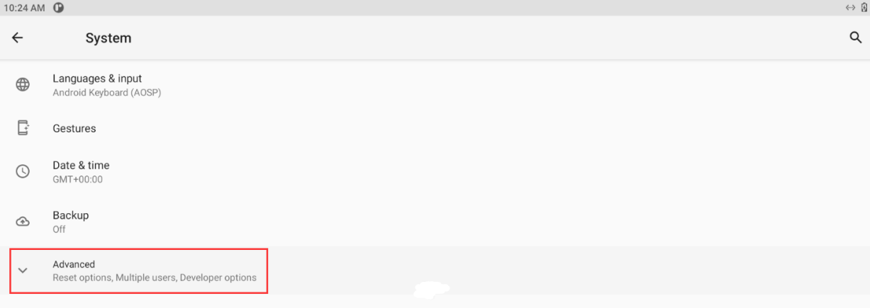
Then select Developer options in the expanded column
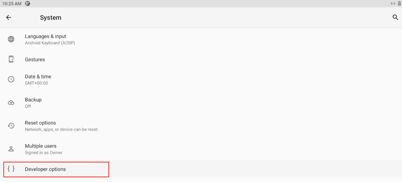
Finally find the USB OTG Mode Switch switch, turn on the switch to switch to Device mode, turn off the switch to switch to Host mode


Use the data cable to connect to adb debugging
First prepare a good quality USB2.0 male-to-male data cable
Then refer to the method of USB OTG mode switching to switch USB OTG to Device mode
Then connect the development board to the Ubuntu PC through the USB2.0 male-to-male data cable. The position of the USB OTG interface on the development board is shown in the figure below:
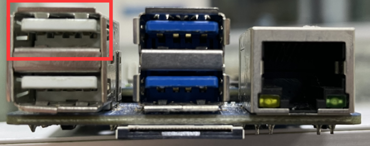
Then install the adb tool on the Ubuntu PC
test@test:~$ sudo apt update
test@test:~$ sudo apt -y install adb
You can view the identified ADB devices through the following command
test@test:~$ adb devices
List of devices attached
S63QCF54CJ device
test@test:~$ lsusb
Bus 003 Device 006: ID 2207:0006
Then you can log in to the android system through the adb shell on the Ubuntu PC

|
test@test:~$ adb shell console:/ $ |
- Execute the following command to remount the Android system
|
test@test:~$ adb root test@test:~$ adb remount |
- Then you can transfer files to the Android system
|
test@test:~$ adb push example.txt /system/ |
Use network connection adb debugging
|
Using the network adb does not require a data cable to connect the computer and the development board, but to communicate through the network, so first make sure that the wired or wireless network of the development board is connected, and then obtain the IP address of the development board, which will be used later. |
Make sure that the service.adb.tcp.port of the Android system is set to port number 5555
console:/ # getprop | grep "adb.tcp"
[service.adb.tcp.port]: [5555]
If service.adb.tcp.port is not set, you can use the following command to set the port number of network adb
|
console:/ # setprop service.adb.tcp.port 5555 console:/ # stop adbd console:/ # start adbd |
Install adb tool on Ubuntu PC
test@test:~$ sudo apt update
test@test:~$ sudo apt install -y adb
Then connect to the network adb on the Ubuntu PC
test@test:~$ adb connect 192.168.1.xxx (IP地址需要修改为开发板的IP地址)
* daemon not running; starting now at tcp:5037
* daemon started successfully
connected to 192.168.1.xxx:5555
test@test:~$ adb devices
List of devices attached
192.168.1.xxx:5555 device
Then you can log in to the android system through the adb shell on the Ubuntu PC
|
test@test:~$ adb shell console:/ # |
How to compile Android11 source code
Download the source code of Android 11
First download the Android 11 source code sub-volume compressed package from the Google network disk
Google Drive
After downloading the sub-volume compression package of the Android 11 source code, please check whether the MD5 checksum is correct, if not, please download the source code again
test@test:~$ md5sum -c RK356X_Android11.tar.gz.md5sum
RK356X_Android11.tar.gz00: OK
RK356X_Android11.tar.gz01: OK
RK356X_Android11.tar.gz02: OK
RK356X_Android11.tar.gz03: OK
RK356X_Android11.tar.gz04: OK
RK356X_Android11.tar.gz05: OK
RK356X_Android11.tar.gz06: OK
Then you need to merge multiple compressed files for decompression

|
test@test:~$ cat RK356X_Android11.tar.gz0* | tar -xvzf - |
Compile the source code of Android 11
First install the software packages required to compile the Android11 source code
test@test:~$ sudo apt-get update
test@test:~$ sudo apt-get install -y git gnupg flex bison gperf build-essential \
zip curl zlib1g-dev gcc-multilib g++-multilib libc6-dev-i386 libncurses5 \
lib32ncurses5-dev x11proto-core-dev libx11-dev lib32z1-dev ccache \
libgl1-mesa-dev libxml2-utils xsltproc unzip liblz4-tool
There is a build.sh compilation script in the source code, and the compilation parameters are as follows
-U: Compile uboot
-K: Compile kernel
-A: compile android
-u: Package and generate update.img and update_spi_nvme.img
-o: Compile OTA package
-d: Specify kernel dts
Compile uboot, kernel, android and package them into update.img
The command to compile and support HDMI 4K display mirroring > (LCD is turned off by default) is as follows:
test@test:~$ cd RK356X_Android11
test@test:~/ RK356X_Android11$ export BOARD=orangepi3b
test@test:~/ RK356X_Android11$ source build/envsetup.sh
test@test:~/ RK356X_Android11$ lunch rk3566_r-userdebug
test@test:~/ RK356X_Android11$ ./build.sh -AUKu
The command to compile and support LCD display mirroring (HDMI > is disabled by default) is as follows:
test@test:~$ cd RK356X_Android11
test@test:~/ RK356X_Android11$ export BOARD=orangepi3b
test@test:~/ RK356X_Android11$ export DUAL_LCD=true
test@test:~/ RK356X_Android11$ source build/envsetup.sh
test@test:~/ RK356X_Android11$ lunch rk3566_r-userdebug
test@test:~/ RK356X_Android11$ ./build.sh -AUKu
After the compilation is complete, the following information will be printed
********rkImageMaker ver 2.1********
Generating new image, please wait...
storage is spinor
Writing head info...
Writing boot file...
Writing firmware...
Generating MD5 data...
MD5 data generated successfully!
New image generated successfully!
********rkImageMaker ver 2.1********
Merging storage firmware, please wait...
storage count = 2
adding spinor_update.img...ok
adding pcie_update.img...ok
Merging firmware success.
Making update_spi_nvme.img OK.
Make update image ok!
/wspace3/RK3566/RK356X_Android11
The final image file will be placed in the rockdev/Image-rk3566_r/ directory. Among them, update.img is the boot image that supports TF card and eMMC, and update_spi_nvme.img is the boot image of NVME SSD
test@test:~/RK356X_Android11$ cd rockdev/Image-rk3566_r
test@test:~/RK356X_Android11/rockdev/Image-rk3566_r $ ls update*
update.img update_spi_nvme.img
Appendix
User Manual Update History
| Version | Date | Update Notes |
| v1.0 | 2023-08-29 | initial version |
| v1.1 | 2023-09-05 | Instructions for using the Orange Pi OS Arch system |
Image Update History
| Date | Update Notes |
| 2023-08-29 |
Orangepicm4_1.0.0_ubuntu_focal_server_linux5.10.160.7z Orangepicm4_1.0.0_ubuntu_jammy_server_linux5.10.160.7z Orangepicm4_1.0.0_debian_bullseye_server_linux5.10.160.7z Orangepicm4_1.0.0_debian_bookworm_server_linux5.10.160.7z Orangepicm4_1.0.0_ubuntu_focal_desktop_xfce_linux5.10.160.7z Orangepicm4_1.0.0_ubuntu_jammy_desktop_xfce_linux5.10.160.7z Orangepicm4_1.0.0_debian_bullseye_desktop_xfce_linux5.10.160.7z Orangepicm4_1.0.0_debian_bookworm_desktop_xfce_linux5.10.160.7z
OrangePiCM4_RK3566_Android11_lcd_v1.0.0.tar.gz OrangePiCM4_RK3566_Android11_spi-nvme_v1.0.0.tar.gz OrangePiCM4_RK3566_Android11_lcd_spi-nvme_v1.0.0.tar.gz
|
| 2023-09-05 |
Opios-arch-aarch64-xfce-opicm4-23.09-linux5.10.160.img.xz
|