Orange Pi 3G- IoT -B
Contents
Orange Pi Introduction
What is Orange Pi 3G-IoT?
It’s an open-source single-board computer. It can run Android4.4、Linux. It uses the MTK serial MT6572 CPU.
What can I do with Orange Pi 3G-IoT?
You can use it to build…
- A computer
- A wireless server
- Games
- Music and sounds
- HD video
- A speaker
- Android
- Scratch
Pretty much anything else, because Orange Pi 3G-IoT is open source.
Who is it for?
Orange Pi 3G-IoT is for anyone who wants to start creating with technology
– not just consuming it. It's a simple, fun, useful tool that you can use to start taking control of the world around you.
Orange Pi 3G-IoT Hardware Specification
| OrangePi 3G-IoT-256MB Hardware Specification | |
| Processor | MT6572 |
| CPU | Quad core ARM® Cortex-A7, Main frequency up to 1.25GHz |
| GPU | ARM Mali-400MP1 GPU |
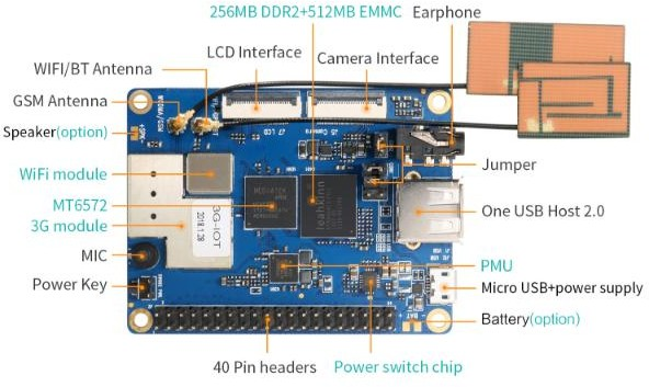
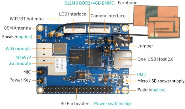
| Memory | Version A: 256MB DDR2+512MB EMMC Flash Version B: 512MB DDR2+4GB EMMC Flash |
| Wireless | WIFI / BT / FM / GPS Four in one |
|
Radio frequency
GSM WCDMA TD-CDMA CDMA2000 |
850/900/1800/1900 |
| B1/B2/B5/B8 | |
| / | |
| / | |
| Display | FWVGA(FPC zif Connector) |
| Capacitance touch | Support (FPC zif Connector) |
| Camera | MIPI Connector |
| SIM Card | mini Single SIM Card |
| TF Card | Support hot-plugging |
|
Audio
Earphone Mic |
For audio input / output |
| For audio input | |
| USB Port | One USB Host, one Micro USB |
| LED | Red for power indicator, Green for status indicator |
| Key | Power button(SW602) |
| Low-level peripherals | 40pin Expansion Headers: GPIO 1.8V, SPI × 2 , I2C × 3, UART×2 |
| Power Supply | Micro USB(5V/2A),Battery(Optional) |
| Software | |
| OS | Android 4.4 |
| Programming support | C, C++, Kotlin, Java, Shell, Python, etc |
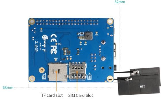
256MB DDR2 + 512MB EMMC Version Specs:
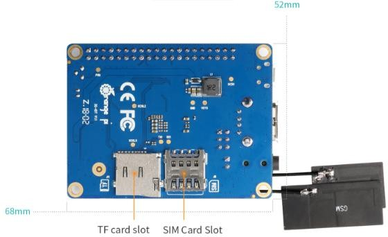
512MB DDR2 + 4GB EMMC Version Specs:
GPIO Specs
| PIN1 | VIO28 PMU | PIN21 | GPIO24 |
| PIN2 | DC5V | PIN22 | GPIO109 |
| PIN3 | SDA_1 | PIN23 | GPIO25 |
| PIN4 | DC5V | PIN24 | GPIO139 |
| PIN5 | SCL_1 | PIN25 | GND |
| PIN6 | GND | PIN26 | EINT0/GPIO30/PWM B |
| PIN7 | EINT4/GPIO26 | PIN27 | SDA_0 |
| PIN8 | UTXD2 | PIN28 | SCL_0 |
| PIN9 | GND | PIN29 | SPI_CS |
| PIN10 | URXD2 | PIN30 | GND |
| PIN11 | URXD1 | PIN31 | SPI_CK |
| PIN12 | EINT10/GPIO56 | PIN32 | EINT15/GPIO90 |
| PIN13 | UTXD1 | PIN33 | SPI_MO |
| PIN14 | GND | PIN34 | GND |
| PIN15 | EINT2/GPIO128/PW A | PIN35 | SPI_MI |
| PIN16 | EINT12/GPIO58 | PIN36 | GPIO145/PWMBL |
| PIN17 | VIO28 PMU | PIN37 | EINT3/GPIO27 |
| PIN18 | EINT14/GPIO89 | PIN38 | EINT5/GPIO144/PWM B |
| PIN19 | GPIO140 | PIN39 | GND |
| PIN20 | GND | PIN40 | GPIO141 |
Using Method
Prepare the Hardware and Software
Hardware Requirement:
- Orange Pi 3G-IoT Development Board
- A PC for compilation with following specs:
64bit CPU
Up to 16GB RAM
UP to 40GB spare disk space
Operation system should up to Ubuntu12.04, it would be better if it is Ubuntu16.04
You could refer to Google file for more details: https://source.android.com/source/building
Software Requirement:
- Orange Pi 3G-IoT SDK
- Orange Pi 3G-IoT Firmware
- Android-image-flash-tool
Power Methods
There are two methods for power supply:
- Micro USB(5V 2A)in for power:
- Battery in for power:
Usually use 4.2V battery to solder on the back side of the development board.
Before Usage
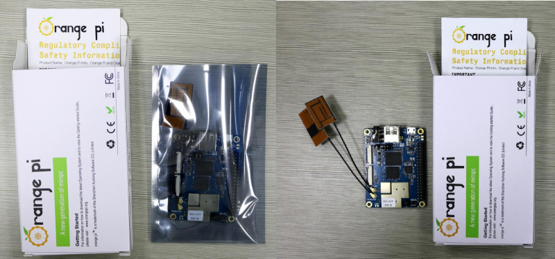
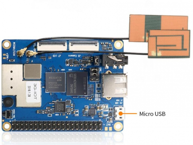
After receiving the product, please put the antennas of the product from the position of Pic 1 to the position of Pic 2 (or to the outside of the board), which can not be attached to the board so as not to affect the signal.
Android Compilation Environment Construction
Download SDK compression package
Orange Pi offers different versions of SDK initial compression packages to facilitate customer rapid development.
Download the compression packages, corresponding to OrangePi_3G-IoT_Android4.4.tar.gz00, OrangePi_3G-IoT_Android4.4.tar.gz01, ...OrangePi_3G-IoT_Android4.4.tar.gz00, a total of eight volume compression packages. After obtaining the volume compressed packages, place all the compressed packages in the same directory, such as
Create directory:
mkdir OrangePi_3G-IoT_Android4.4
Copy Volume Compression Packet to this directory:
cp -rf OrangePi_3G-IoT_Android4.4.tar.gz* OrangePi_3G-IoT_Android4.4/
Merge Compression Packet:
cat OrangePi_3G-IoT_Android4.4.tar.gz*>OrangePi_3G-IoT_Android4.4.tar.gz
Unzip:
tar xzvf OrangePi_3G-IoT_Android4.4.tar.gz
Construct Compilation Environment
It could also refer to Google file: http://source.android.com/source/initializing.html
- Install JDK
Compilation of Android4.4 is base on JAVA6, it needs to first install OpenJDK, gcc4.4 before compilation.
Command for installing:
sudo apt-get install openjdk-6-jdk
sudo apt-get install gcc-4.4
If the installation path is /usr/lib/jvm/jdk1.6.0_31 when configure environment variable of JAVA, then execute the the following command on terminal to configure the data.
export JAVA_HOME=/usr/lib/jvm/jdk1.6.0_31
export PATH=$JAVA_HOME/bin:$PATH
export CLASSPATH=.:$JAVA_HOME/
lib:$JAVA_HOME/lib/tools.jar
Install Software Package
For Ubuntu12.04:
sudo apt-get update
sudo apt-get install git-core gnupg flex bison ccache gperf libsdl1.2-dev libesd0-dev libwxgtk2.6-dev build-essential zip curl libncurses5-dev zlib1g-dev valgrind libc6-dev lib32ncurses5-dev x11proto-core-dev
libx11-dev lib32readline-gplv2-dev lib32z1-dev libgl1-mesa-dev gcc-4.4 g++-4.4 g++-4.4-multilib g++-multilib mingw32 tofrodos python-markdown libxml2-utils xsltproc wine
For Ubuntu14.04:
sudo apt-get update
sudo apt-get install git-core gnupg flex bison ccache gperf libsdl1.2-dev libesd0-dev libwxgtk2.8-dev build-essential zip curl libncurses5-dev zlib1g-dev valgrind libc6-dev lib32ncurses5-dev x11proto-core-dev
libx11-dev lib32readline-gplv2-dev lib32z1-dev libgl1-mesa-dev g++-multilib g++-4.8-multilib mingw32 tofrodos python-markdown
libxml2-utils xsltproc libc6-dev-i386 lib32z1 lib32ncurses5 lib32bz2-1.0 lib32readline-gplv2-dev wine
We could process to SDK compilation after finished the above.
Compilation of SDK Source Code
Full compilation
There are many compilation shell scripts for development.
Directory is: SDK/code/orangepi/scripts
$ cd code/orangepi/scripts
$ ls
anr_kk.sh auto.sh clean.sh init_project.sh tar_img.sh
auto.sh is automatically compilation script
clean.sh is automatically scavenging the compiled result script
tar_img.sh is packing script
One the directory of code/orangepi/scripts, we could execute automatically compilation script:
If the board is: 32g4g
$ ./auto.sh IoT03_mt6572_emmc_b1258_
32g4g_ry_smt_v1.1 v00 eng
If the board is: 4g2g
$ ./auto.sh IoT03L_mt6572_lca_b1258_
wg_4g2g_ry_smt_v1.1 v00 eng
The meaning of the parameter is:
- $1 project_info [eg: IoT03L_mt6572
_lca_b1258_wg_4g2g_ry_smt_v1.1] - $2 version_info [eg: v00 v01 ...]
- $3 compile_mode [eng:user userdebug eng]
Module compilation
Usually use the following command to change Kernel file:
./mk -o=TARGET_BUILD_VARIANT=[user/userdebug/eng] projName n K && ./mk -o=TARGET_BUILD_VARIANT=[user/userdebug/eng] projName r bootimage
For example, if project is: hexing72_cwet_kk
./mk -o=TARGET_BUILD_VARIANT=eng hexing72_cwet_kk n k && ./mk -o=TARGET_BUILD_VARIANT=eng hexing72_cwet_kk r bootimage
You could refer to MT6592_Driver_All_In_One_Part.pdf (after unzip SDK you will have this file) for modification of driver compilation.
Android Firmware Flashing
Relevant keys and connectors for firmware flashing of 3G-IoT:
After compilation, all the firmware will generate on the directory of:
code/IoT03_b1258_32g4g_
ry_smt_v1.1 or code/IoT03L_
b1258_wg_4g2g_ry_smt_v1.1 ,
and packed into compression
file as the name of IoT03L_b1258
_wg_4g2g_ry_smt_v1.1_
20180403182516_v00_eng.zip.
IoT03L_b1258_wg_4g2g_ry_smt_v1.1
├── images
│ ├── boot.img
│ ├── lk.bin
│ ├── logo.bin
│ ├── MT6572_Android_scatter.txt
│ ├── preloader_hexing72_cwet_lca.bin
│ ├── ramdisk.img
│ ├── ramdisk-recovery.img
│ ├── recovery.img
│ ├── secro.img
│ ├── system.img
│ └── userdata.img
└── modem
├── APDB_MT6572_S01_MAIN
2.1_W10.24
├── _APDB_MT6572_S01_MAIN
2.1_W10.24.check
├── APDB_MT6572_S01_MAIN
2.1_W10.24_ENUM
├── BPLGUInfoCustomAppSrcP
_MT6572_S00_MOLY_WR8_W1315_MD_WG_MP_V47_1_wg_n
├── catcher_filter_1_wg_n.bin
├── DbgInfo_WR8.W1315.MD.WG.MP
_HEXING72_CWET_KK_HSPA_MOLY_WR8_W1315_MD_WG_MP
_V47_2017_10_26_22_35_1_wg_n
├── modem_1_wg_n.img
└── modem_1_wg_n.mak
After the above steps, you could refer to the previous section to flash image.
Or you could use the image we have compiled and pack:
http://www.orangepi.org/html/hardWare/computerAndMicrocontrollers/service-and-support/Orange-Pi-3G-IoT-B.html
Unzip Android4.4 image via the following command:
$ rar x IoT03L_b1258_wg_4g2g_ry_smt_v1.1.rar
You could get the list of firmware after ran the above command, or you could also compile by yourself with reference of previous section.
Supporting OS of PC:
- Windows 10
- Windows 7 (32/64bit)
- Windows 8 (32/64bit)
- Ubuntu10.04 / 12.04 / 14.04 (32/64bit)
Flash Tool Introduction
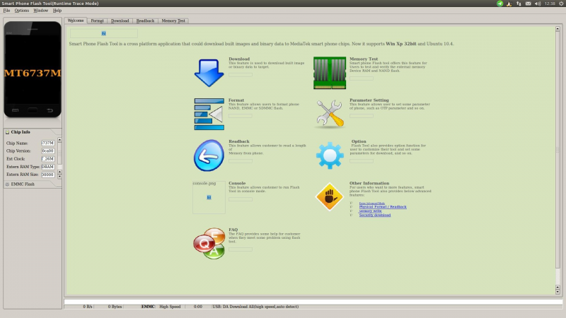
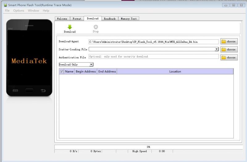
You could download the Smart Phone Flash Tool on the download page of Orange Pi 3G-IoT section. There are tools for Windows and Linux version, you could select a suitable version according to your PC environment.
Interface like the following:
Using method for both Windows and Linux versions are same, here will illustrate with Linux version
Method for Image Flashing
MTK suggesting Ubuntu12.04 version, if it is not this version and cannot connect to the computer, then you need to:
$sudo apt-get remove modemmanager
$sudo /etc/init.d/udev retstart
Reboot your computer
Download corresponding MTK driver according to your OS when running on Windows
Unzip Driver_Auto_Installer_EXE_v5.1453.03.rar
Install
- Unzip and open flash tool
$ unzip SP_Flash_Tool_v5.1644_Linux.zip
$ cd SP_Flash_Tool_v5.1644_Linux
$ sudo ./flash_tool.sh
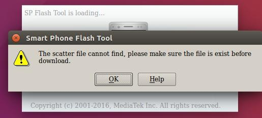
If it is the first time you use this software, you might receive the warn like the following. It is normal to receive this, you could click OK enter into the software. In the future you could manually specified the path of Scatter File.
- Enter into flash mode
a.Switch into Download page like the following:
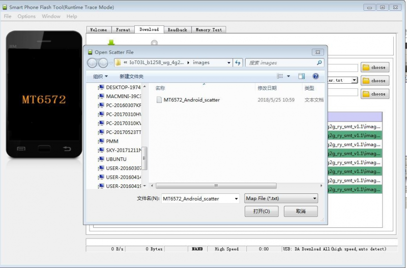
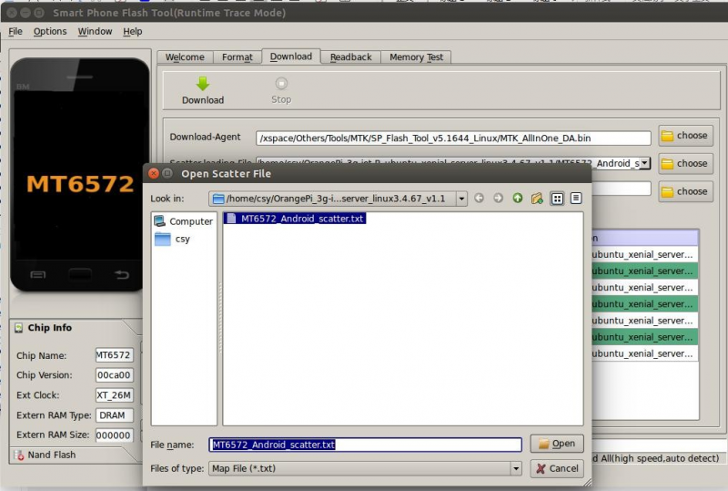
b.Click choose on the right side of Scatter-loading File and select the path of Scatter File like the following:
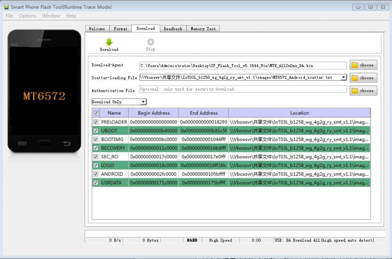
c.After double click the selection, the partition information display section will automatically fill the path of each partition file and the absolute starting address to which they are to be flashed.
d.In the top left corner of partition information display section, there would be a drop-down menu. Three of this options:
Format All + Download // Format all information on the partitions and re-download the selected partition
Firmware Upgrade // Update the difference on the selected partition
Download Only // Re-download no matter there is difference or not
Please note it: Usually update firmware you only need to select Firmware Upgrade, please do not
select Format All + Download
It you select Format All, you will lose the calibration information which we worked before sending out products. If this situation is inadvertent, please contact the Orange Pi service and obtain the calibration parameters through the machine code, and re-flash the calibration parameters.
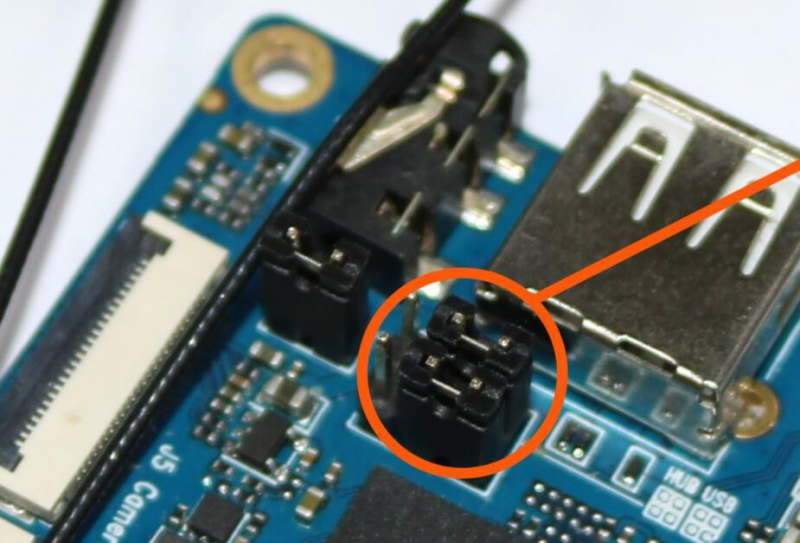
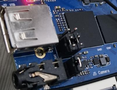
e.Insert Jumper cap:
f.Then connect with USB on PC and Mirco USB on Orange Pi via USB cable, the red LED will light up.
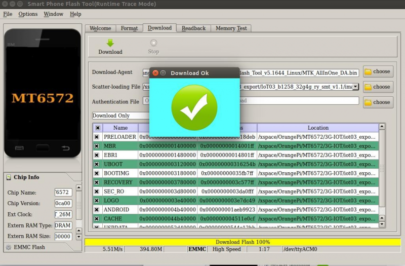
g.Click Download button
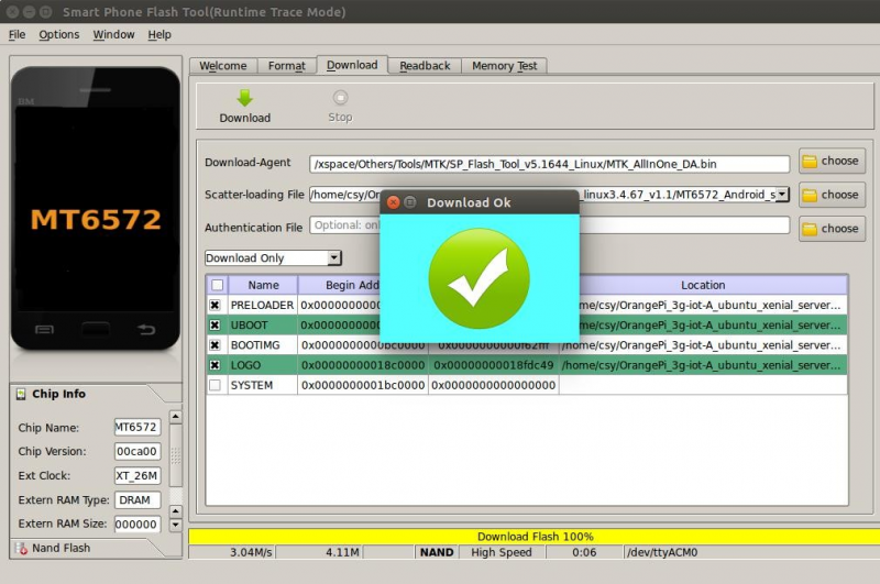
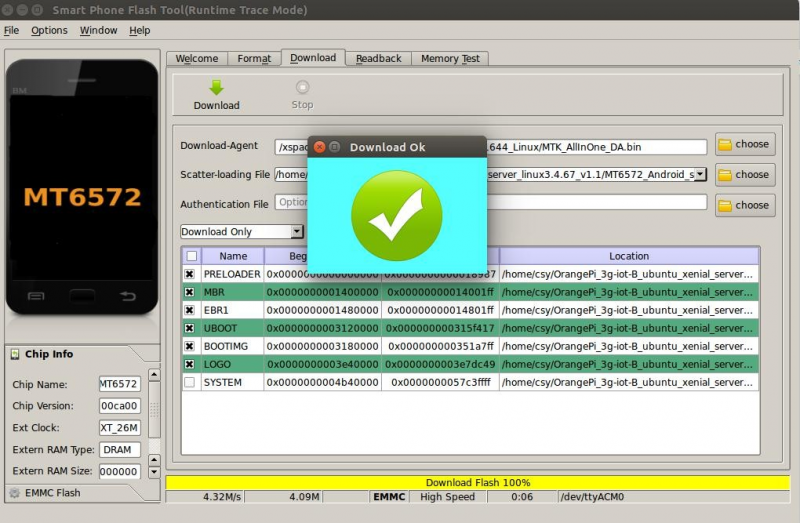
h.The interface would show like the following after downloaded:
i.Take of the USB cable and insert Micro USB power supply
Wait around 5 seconds, it will display the charging interface of shutdown
When the Power button is loosened after 5 seconds, the system will start to enter the system
When the updated partition is more, the first boot will take a long time (the full partition update needs 8min), please be patient.
Windows OS would require to download SP_Flash_Tool_v5.1644_Win.zip, unzip and install it. Then could refer to the manual of Linux to flash image.
Linux Compilation Environment Construction
Get Linux Source Code
- Orange Pi Source Code Downloader
$ sudo apt-get install git
$ git clone https://github.com/orangepi-xunlong/OrangePi_Build.git
$ cd OrangePi_Build
$ ls
Build_OrangePi.sh lib README.md
- Run the Downloader
$ ./Build_OrangePi.sh
Enter the root password and press Enter
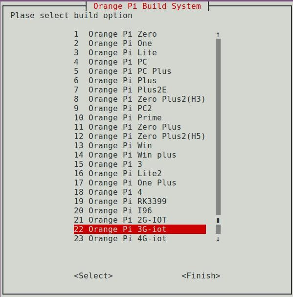
Choose 0 Build system with kernel/uboot/rootfs, enter the development board model selection interface.
Choose 22 orangepi 3G-IoT,Press Enter and start download Orange Pi 3G-IoT Linux Source Code
The downloaded source code will be stored in the same directory as OrangePi_Build. Orange Pi 3G-IoT Linux source code directory structure is as follows
├── bootloader Store preloader and lk source code
├─ build.sh -> scripts/build.sh Compile the startup script
├── external Store additional configuration files and partial code
├── kernel Linux Kernel source
├── output; Store the output file, generate it after compiling the source code
├── scripts; Script file used by the compilation process
└── toolchain; Cross compilation toolchain
6 directories, 1 file
Compilation of Linux Source Code
- Execute the compilation start up script
$ cd Orange Pi 3G-IoT
$ ./build.sh
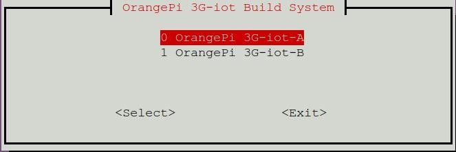
According to the board model to choose and press Enter.
Enter the root password and press Enter, then select the function needed to execute.
The functions of each option are as follows:
- 0 Build Release Image Compile full image
- 1 Build Rootfs Compile Rootfs
- 2 Build Uboot Compile preloader and lk
- 2 Build Linux Compile kernel source code
Take the A board as an example, choose 0 Build Release Image, generate the following complete firmware package
output/images/
├── OrangePi_3g-IoT-A_ubuntu_xenial_server_linux3.4.67_v1.1
│ ├── boot.img
│ ├── boot_nand.img
│ ├── boot_sd.img
│ ├── lk.bin
│ ├── logo.bin
│ ├── MT6572_Android_scatter.txt
│ ├── preloader_hexing72_cwet_lca.bin
│ └── rootfs.img
├── OrangePi_3g-IoT-A_ubuntu_
xenial_server_linux3.4.67_v1.1.tar.gz
Android burning tool can be used to burn the above image file into flash, please refer to Android firmware burning chapter.
Linux Firmware Flashing
At present, the Linux system do not support modem and LCD screen。
You can only login system via a serial port。After connecting to wifi, you can log in via ssh。
When programming the system, the jumper cap connection method is as follows.
3G-IoT-A linux firmware burning
Burn the preloader, lk, boot.img to the on-board nand flash with the burning tool.
├── boot.img
├── boot_nand.img
├── boot_sd.img
├── lk.bin
├── logo.bin
├── MT6572_Android_scatter.txt
├── preloader_hexing72_cwet_lca.bin
└── rootfs.img
The previous "Android Firmware Burning" has introduced how to use the burning tool, so I won't go into details here, just open the burning tool directly.
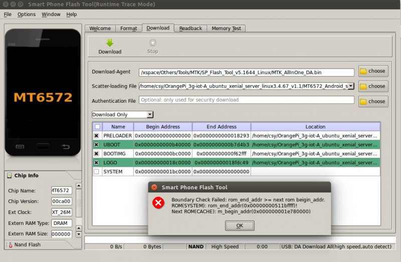
a.We click on the far right of the Scatter-loading File column And select the path of Scatter File, as shown below.
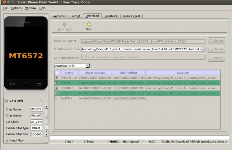
b.Disconnect the board from the PC first, and click the Download button
c.Next, use a USB download cable to connect the host's USB to the machine's MircoUSB interface.
d.Only the lk and kernel were burned in the front. Since 3G-IoT-A only has 512M on-board storage, there is a problem of insufficient space, so you need to burn the rootfs to a TF card, and prepare a TF card with more than 8G and class10. After formatting. Burn roofs.img as follows
pv rootfs.img | sudo dd of=/dev/sdb bs=1M
sdb is the device file corresponding to the TF card
If it is a windows system, you can also use Win32DiskImager software to burn.
Insert the tf card into the board, and it can start after power on. (Note that 3G-IoT-A and other two LED lights are on, then plug in the serial port, otherwise it will not start)
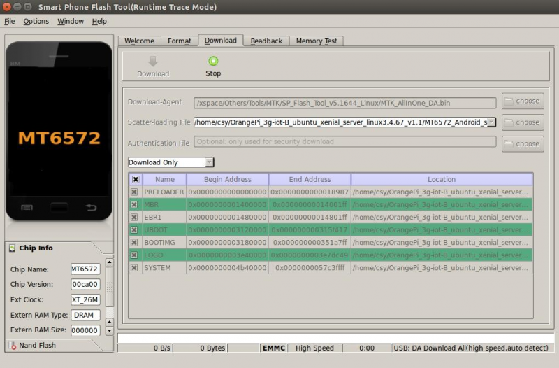
3G-IoT-B linux firmware burning
The board has 4G of onboard storage, so you can burn all the images directly to the onboard EMMC.
a.We click on the far right of the Scatter-loading File column
And select the path of Scatter File, as shown below
b . First disconnect the board from the PC and click the Download button
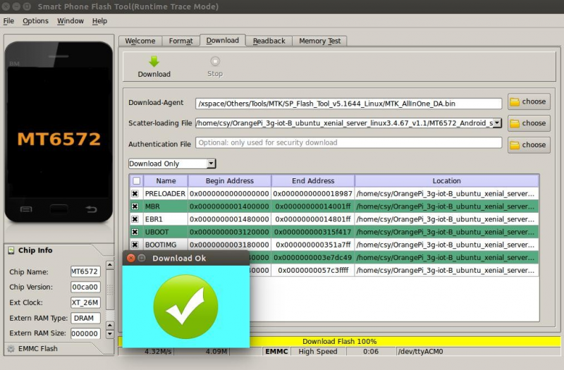
C. Next, use a USB download cable to connect the host's USB to the machine's MircoUSB interface. Burning completed
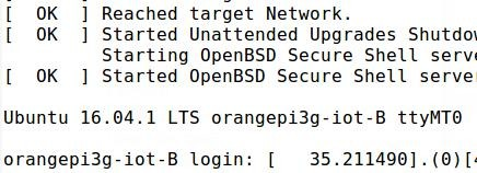
Start the system.
Connect the board to a 5V2A power adapter. Connect the serial port to see the system startup。
If the onboard space is not enough, you can burn the rootfs to the TF card. Proceed as follows.
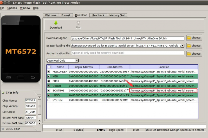
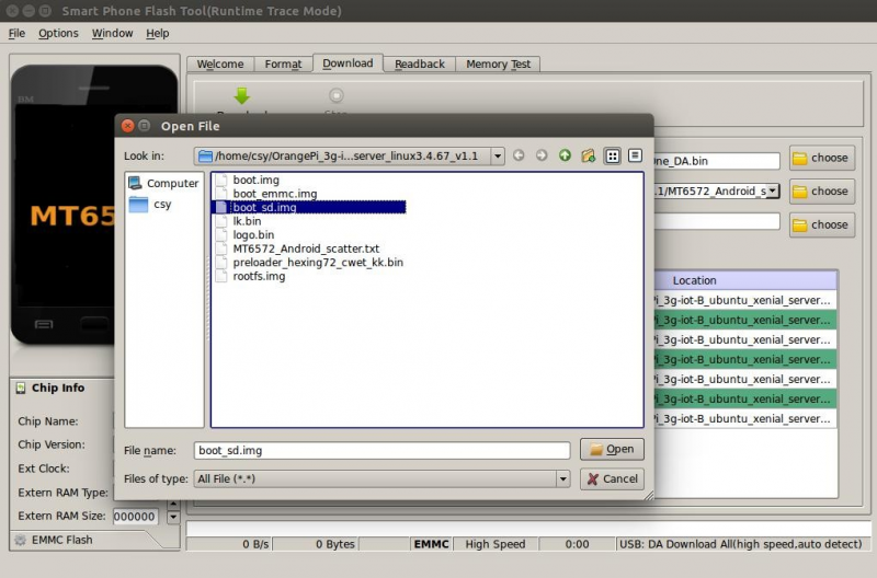
Burn boot.img that supports mounting TF card rootfs
Click on the content in the box below
In the pop-up window, select boot_sd.img.
Download completed
Burn rootfs to TF card
Prepare a TF card above 8G and class10. After formatting. Burn roofs.img as follows
pv rootfs.img | sudo dd of=/dev/sdb bs=1M
sdb is the device file corresponding to the TF card
If it is a windows system, you can also use Win32DiskImager software to burn.
Start the system
Insert the tf card into the board and start it after power on.
Serial Debugging Tool
First need to prepare a USB to TTL serial cable, need to support 921600 baud rate
The debugging serial port of 3G-IoT is serial port 1, which has been led to 40pin, and the baud rate is 921600.
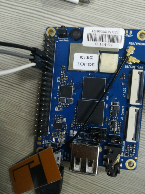
Connect the serial cable as shown below. The functions of the different color lines are as follows:
- Black——GND
- Green——RX
- White——TX
Usage based on Windows platform
In the process of using Orange Pi for project development, in order to get more debugging information, Orange Pi defaults support serial port information debugging. For developers, just prepare the materials mentioned above and can easily get serial debugging information. The serial port debugging tools used by different upper computers are similar, basically refer to the following ways to deploy. There are many tools for serial port debugging using the Windows platform. The commonly used tools are Putty. This section uses putty as an example for deployment.
- Install USB driver
Download the latest version of the driver PL2303_Prolific_DriverInstaller_v130.zip, download and extract.
Select application installation as an administrator
Waiting for installation and click.
- Download and install Putty
Putty can be downloaded from the address below, please choose the version that suits your development environment.
https://www.chiark.greenend.org.uk/~sgtatham/putty/latest.html
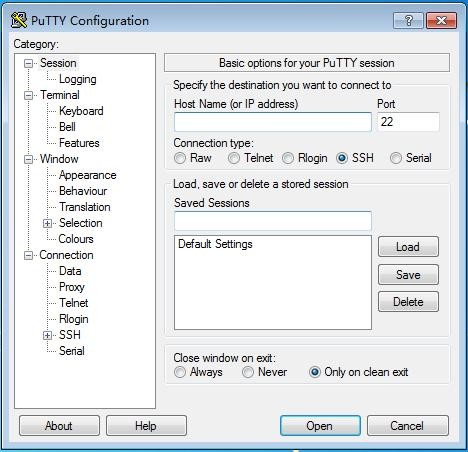
Double-click the downloaded putty.exe to open putty. The software interface is shown below.
- Acquisition of device information
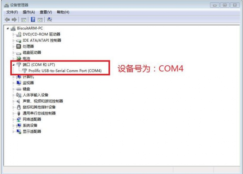
In Windows 7, we can check whether the serial port connection is normal and the serial port device No. through Device Manager. If the device is not recognized properly, please check if the driver is installed successfully. If there is a problem with the driver installation, try using the 360 Driver Master to scan the installation driver.
- Putty configuration
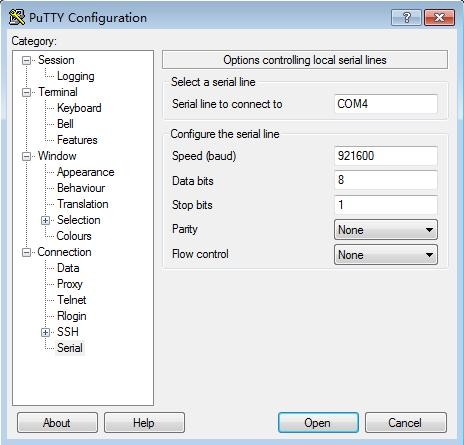
Set the serial port to the corresponding port number (COM4), turn off the flow control, and set the speed to 921600.
- Start debugging serial output
When the Orange Pi is powered on, putty will automatically print the serial port log information.
Usage based on Linux platform
There is a little difference using putty between Windows platform and Linux platform. The following mainly explains the differences. All operations are based on the Ubuntu 14.04 system.
- Install and start Putty
$ sudo apt-get install putty
$ sudo putty
- Configuration Putty
The serial port number can be viewed via ls /dev/ttyUSB*
The baud rate needs to be set to 921600
And turn off flow control
Other settings
Connect WIFI
To configure wireless, must know ssid and psk (account, password), enter the corresponding wlan*, ssid, psk
$ sudo vi /etc/network/interfaces
(add the following)
auto wlan0
iface wlan0 inet dhcp
wpa-ssid xxxx
wpa-psk xxxx
Then execute /etc/init.d/networking restart,wireless connected.
Usage of GPIO
Modify and Display of the GPIO Status Under ADB Mode
Get the Open/Close Status of GPIO : cat /sys/devices/virtual/misc/mtgpio/pin
Enter the command under ADB mode: cat /sys/devices/virtual/misc/mtgpio/pin , then it will show:
pin: [mode] [pull_sel] [din] [dout] [pull en] [dir] [ies] [smt]
0:11101010
1:01101010
、、、、、、
22:1-100-10-1-1
、、、、、、、
42:00000110
Corresponding meaning per row:
IO Number:mode,pull select,input value,output value,pull enable,direction,ies
Modify the Status of GPIO:
You could get the 40pin GPIO specifications from this manual or from schematic which have been uploaded to our official website: http://www.orangepi.org/downloadresources/. For example the 37th pin on 40pins is GPIO123,
echo -wdout123 1 > pin -This is Set the GPIO to output high level
echo -wdout123 0> pin -This is Set the GPIO to output high level
History
| Ver | Data | Author | Brief | Publish | Memo |
| 1.1 | 2018-05-25 | Engineer Pan | Create Documentation | 2018-6-14 | |
| 1.2 | 2018-10-18 | Engineer Pan | Usage of GPIO | 2018-10-19 | |
| 1.3 | 2019-02-21 | Engineer Pan | compilation script Page10 | 2019-02-21 | |
| 1.4 | 2019-04-15 | csy | Linux source code compilation and serial port debugging | 2019-04-17 | |
| 1.5 | 2020-03-24 | csy | Linux source code compilation | 2020-03-24 | |
Download the Orange Pi 3G-IoT User Manual
For more information on using the Orange Pi 3G-IoT, please see the Orange Pi 3G-IoT User Manual . (Click to download)
