Orange Pi 5 Ultra
Orange Pi 5 Ultra
User Manual

Contents
- 1 Basic features of Orange Pi 5 Ultra
- 2 Introduction to the use of development board
- 2.1 Prepare the necessary accessories
- 2.2 Download the development board image and related information
- 2.3 How to burn Linux image to TF card based on Windows PC
- 2.4 Method of burning Linux image to TF card based on Ubuntu PC
- 2.5 Method for burning Linux images to eMMC
- 2.6 Method for burning Linux images to SPIFlash+NVMe SSD
- 2.7 Method for burning Linux images to SPIFlash+USB storage devices
- 2.8 Method of burning Android image to TF card
- 2.9 Method for burning Android images to eMMC
- 2.10 Method for burning Android images to SPIFlash+NVMe SSD
- 2.11 Method for burning Orange Pi OS (Droid) image to TF card
- 2.12 Burn Orange Pi OS (Droid) image to SPIFlash+NVMe SSD
- 2.13 How to clear SPIFlash using RKDevTool
- 2.14 Start the Orange Pi Development Board
- 2.15 How to use the debug serial port
- 2.16 Power supply instructions using the 5V pin in the 40pin interface of the development board
- 3 Instructions for using Ubuntu/Debian Server and Xfce desktop system
- 3.1 Supported Linux image types and kernel versions
- 3.2 3.2. Linux 5.10 system compatibility
- 3.3 Linux 6.1 system compatibility
- 3.4 Linux command format description in this manual
- 3.5 Linux system login instructions
- 3.5.1 3.5.1.Linux system default login account and password
- 3.5.2 3.5.2. How to set up automatic login for Linux system terminal
- 3.5.3 Linux desktop system automatic login instructions
- 3.5.4 How to set up automatic login for root user in Linux desktop system
- 3.5.5 How to disable the desktop in Linux desktop system
- 3.6 Onboard LED light test instructions
- 3.7 Network connection test
- 3.8 SSH remote login development board
- 3.9 How to use ADB
- 3.10 How to upload files to the Linux system of the development board
- 3.11 HDMI test
- 3.12 How to use Bluetooth
- 3.13 USB interface test
- 3.14 Audio Test
- 3.15 Temperature sensor
- 3.16 40 Pin Interface Pin Description
- 3.17 How to install wiringOP
- 3.18 40pin interface GPIO, I2C, UART, SPI, CAN and PWM test
- 3.19 How to use wiringOP hardware PWM
- 3.20 Installation and use of wiringOP-Python
- 3.21 Hardware watchdog test
- 3.22 Check the serial number of the RK3588 chip
- 3.23 How to install Docker
- 3.24 How to download and install the arm64 version of balenaEtcher
- 3.25 How to install Baota Linux Panel
- 3.26 Set up Chinese environment and install Chinese input method
- 3.27 How to remotely log in to the Linux system desktop
- 3.28 Test of some programming languages supported by Linux system
- 3.29 How to install QT
- 3.30 ROS installation method
- 3.31 How to install kernel header files
- 3.32 How to use 10.1 inch MIPI LCD screen
- 3.33 Instructions for using the power on/off logo
- 3.34 Test Methods for OV13850 and OV13855 MIPI Cameras
- 3.35 How to use ZFS file system
- 3.36 How to install and use CasaOS
- 3.37 Methods of using NPU
- 3.37.1 Prepare tools
- 3.37.2 Install RKNN-Toolkit2 on Ubuntu PC
- 3.37.3 Model conversion and model inference using RKNN-Toolkit2
- 3.37.4 Call the C interface to deploy the RKNN model to the development board to run
- 3.38 How RK3588 uses Baidu Feijiang
- 3.39 RK3588 How to run the RKLLM large model
- 3.39.1 Introduction to RKLLM
- 3.39.2 Prepare tools
- 3.39.3 Detailed steps for model conversion and source code compilation on Ubuntu PC
- 3.39.4 Detailed steps for development board deployment and operation
- 3.39.5 Detailed steps for deploying and running the server on the development board
- 3.39.6 Performance test results of RK3588 running RKLLM large model
- 3.40 How to shut down and restart the development board
- 4 Orange Pi OS Arch system usage instructions
- 5 Linux SDK - Orangepi build usage instructions
- 6 Instructions for using Android 13 system
- 6.1 Supported Android versions
- 6.2 Adaptation of Android Features
- 6.3 WIFI connection testing method
- 6.4 Bluetooth testing method
- 6.5 10.1 inch MIPI screen usage method
- 6.6 Testing Method for OV13850 and OV13855 MIPI Cameras
- 6.7 40pin interface GPIO, UART, SPI, and PWM testing
- 6.8 Usage of ADB
- 6.9 Testing Method for HDMI RX
- 7 Compilation method of Android 13 source code
- 8 OpenWRT System User Manual
- 8.1 OpenWRT version
- 8.2 OpenWRT adaptation situation
- 8.3 The first boot to expand rootfs
- 8.4 Method of logging into the system
- 8.5 Method of modifying LAN port IP address through command line
- 8.6 Method for changing root password
- 8.7 USB interface testing
- 8.8 USB Wireless Network Card Test
- 8.9 Installing software packages through the command line
- 8.10 OpenWRT management interface installation software package
- 8.11 Using Samba Network Sharing
- 8.12 Zerotier User Manual
- 9 Compilation method of OpenWRT source code
- 10 Appendix
Basic features of Orange Pi 5 Ultra
What is Orange Pi 5 Ultra
Orange Pi 5 Ultra uses Rockchip RK3588, a new generation of octa-core 64-bit ARM processor, which includes quad-core A76 and quad-core A55. It adopts Samsung's 8nm LP process technology, with a large core frequency of up to 2.4GHz. It integrates ARM Mali-G610 MP4 GPU, embedded high-performance 3D and 2D image acceleration modules, built-in AI accelerator NPU with up to 6 Tops computing power, 4GB/8GB/16GB (LPDDR5) memory, and has up to 8K display processing capabilities.
Orange Pi 5 Ultra introduces a wide range of interfaces, including HDMI output, HDMI input, Wi-Fi6, M.2 M-key PCIe3.0x4, 2.5G network port, USB2.0, USB3.1 interface and 40pin expansion pin header, etc. It can be widely used in high-end tablets, edge computing, artificial intelligence, cloud computing, AR/VR, smart security, smart home and other fields, covering all industries of AIoT.
Orange Pi 5 Ultra supports Orange Pi OS, the official operating system developed by Orange Pi. It also supports operating systems such as Android 13, Debian11, Debian12, Ubuntu20.04 and Ubuntu22.04.
Purpose of Orange Pi 5 Ultra
We can use it to achieve:
- A Linux desktop computer.
- A Linux network server.
- Android tablet.
- Android game consoles, etc
Of course, there are many more functions. Relying on a powerful ecosystem and a wide range of expansion accessories, Orange Pi can help users easily realize the delivery from creativity to prototype to mass production. It is an ideal creative platform for makers, dreamers and amateurs.
Orange Pi 5 Ultra hardware features
| Hardware Features | |
| CPU | • Rockchip RK3588 (8nm LP process)
• 8-core 64-bit processor • Quad-core Cortex-A76 and quad-core Cortex-A55 big and small core architecture • The main frequency of the big core is up to 2.4GHz, and the main frequency of the small core is up to 1.8GHz |
| GPU | • Integrated ARM Mali-G610
• OpenGL ES1.1/2.0/3.2, OpenCL 2.2 and Vulkan 1.2 |
| NPU | • Built-in AI accelerator NPU with up to 6 Tops computing power
• Support INT4/INT8/INT16 mixed operations |
| video | • 1 * HDMI 2.1,Maximum support 8K @60Hz
• 1 * HDMI Input, up to4K@60FPS • 1 * MIPI D-PHY TX 4Lane |
| Memory | 4GB/8GB/16GB(LPDDR5) |
| Camera | • 2 * MIPI CSI 4Lane
• 1 * MIPI D-PHY RX 4Lane |
| PMU | RK806-1 |
| Onboard storage | • eMMC socket, can be connected to external eMMC module
• 16MB QSPI Nor FLASH • MicroSD (TF) Card Slot • PCIe3.0x4 M.2 M-KEY (SSD) Slots |
| Ethernet | 1 * PCIe 2.5G Ethernet port(RTL8125BG ) |
| WIFI+BT | • Onboard Wi-Fi 6E+BT 5.3/BLE Modules:AP6611
• Wi-Fi interface:SDIO3.0 • BT interface:UART/PCM |
| Audio | • 3.5mm Headphone jack Audio input/output
• Onboard MIC input • 2 * HDMI Output |
| PCIe M.2 M-KEY | • PCIe 3.0 x 4 lanes,For connecting NVMe SSD |
| USB interface | • 1 * USB3.0 support Device or HOST model
• 1 * USB3.0 HOST • 2 * USB2.0 HOST |
| 40pin Extension pin header | For expansion UART、PWM、I2C、SPI、CAN and GPIO interface |
| Debug serial port | Included in 40PIN expansion port |
| LED Light | RGB LED three-color indicator |
| button | 1 * MaskROM Key,1 * Power button |
| powered by | Type-C Interface power supply 5V/5A |
| Supported operating systems | Orange Pi OS(Droid)、Orange Pi OS(Ar ch)、Android13、Debian11、Debian12、Ubuntu20.04 and Ubuntu22.04 Other operating systems |
| Appearance Specifications | |
| Product size | 89mm*56mm |
| weight | 58g |
| File:Orange Pi 5 Ultra-image1. png{width=“0.255 55555555555554in” h eight=“0.27638888 88888889in”}range Pi™ is a registered trademark of Shenzhen Xunlong Software Co., Ltd. |
Orange Pi 5 Ultra top and bottom views
Top View:

Bottom layer view:

Orange Pi 5 Ultra interface details


The diameter of the four positioning holes is 2.7mm
Introduction to the use of development board
Prepare the necessary accessories
TF card, minimum 16GB capacity (32GB or above recommended), class 10 or above high-speed SanDisk card.

TF card reader, used to burn the image into the TF card.

Display with HDMI interface.

HDMI to HDMI cable, used to connect the development board to an HDMI monitor or TV for display.
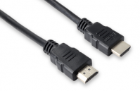
Note that if you want to connect a 4K or 8K display, please make sure the HDMI cable supports 4K or 8K video output.
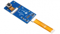
10.1-inch MIPI screen, used to display the system interface of the development board (this screen is common to the adapter board and OPi5Plus/OPi5B/OPi5/OPi5Pro/OPi5Max/OPi5Ultra).

Power adapter: Orange Pi 5 Ultra recommends using a 5V/5A Type-C power adapter.

The Type-C power interface of the development board does not support the PD negotiation function and only supports a fixed 5V voltage input.
A USB mouse and keyboard. Any standard USB mouse and keyboard will do. The mouse and keyboard can be used to control the Orange Pi development board.

USB camera

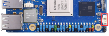
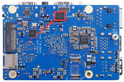
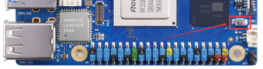
5V cooling fan. As shown in the figure below, there is an interface for connecting the cooling fan on the development board, and the interface specification is 2pin 1.25mm spacing.
The fan on the development board can adjust the speed and switch through PWM.
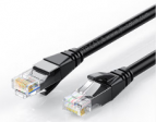
100M or 1000M Ethernet cable, used to connect the development board to the Internet.
USB2.0 male-to-male data cable, used for burning images and using ADB and other functions.

13MP OV13850 camera with MIPI interface.
OV13855 camera with 13MP MIPI interface.

3.3V USB to TTL module and DuPont cable. When using the serial port debugging function, a USB to TTL module and DuPont cable are required to connect the development board and the computer.
![G7U7JZX(V`L$`A6864]38$P](/orangepiwiki/images/thumb/2/2e/Orange_Pi_5_Ultra-image20.png/215px-Orange_Pi_5_Ultra-image20.png)

A personal computer with Ubuntu and Windows operating systems installed.


![G7U7JZX(V`L$`A6864]38$P](/orangepiwiki/index.php/File:Orange_Pi_5_Ultra-image20.png)

| 1 | Ubuntu22.04 PC | Optional, used to compile Linux source code |
| 2 | Windows PC | Used to burn Android and Linux images |
- The download link for the Chinese version is:

The download link for the English version is:

The data mainly includes
Android source code:Save on Baidu Cloud and Google Drive.
Linux source code:Saved on Github.
User Manual and Schematics:Save on Baidu Cloud and Google Drive
Official Tools:It mainly includes the software needed during the use of the development board.
Android Image:Save on Baidu Cloud and Google Drive.
Ubuntu Image:Save on Baidu Cloud and Google Drive.
Debian Image:Save on Baidu Cloud and Google Drive.
Orange Pi OS Image:Save on Baidu Cloud and Google Drive.
OpenWRT Image:Save on Baidu Cloud and Google Drive.

How to burn Linux image to TF card based on Windows PC
Note that the Linux image mentioned here specifically refers to the Linux distribution image such as Debian, Ubuntu, OpenWRT or OPi OS Arch downloaded from the Orange Pi download page.
How to burn Linux image using balenaEtcher
- First, prepare a TF card with a capacity of 16GB or larger. The transmission speed of the TF card must be class10 or above. It is recommended to use a TF card from a brand such as SanDisk.
- Then use the card reader to insert the TF card into the computer.
- Download the compressed Linux operating system image file you want to burn from the Orange Pi data download page, and then use decompression software to decompress it. Among the decompressed files, the file ending with ".img" is the operating system image file, which is generally more than 2GB in size.
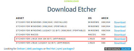
- Then download the burning software for the Linux image——balenaEtcher,Download address:
- After entering the balenaEtcher download page, click the green download button to jump to the software download location.

Then you can choose to download the Portable version of balenaEtcher. The Portable version does not need to be installed, just double-click to open it and you can use it.

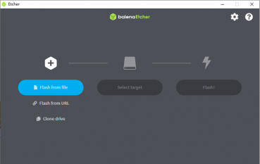
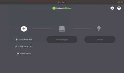
If you downloaded the version of balenaEtcher that needs to be installed, please install it before using it. If you downloaded the portable version of balenaEtcher, just double-click to open it. The interface of balenaEtcher after opening is as shown below:


If the following error is prompted when opening balenaEtcher:

Select balenaEtcher, right-click it, and then choose Run as administrator.
![]()
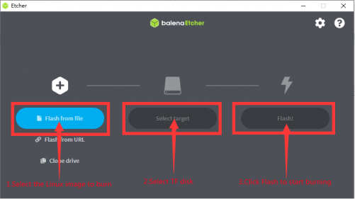
The specific steps to use balenaEtcher to burn the Linux image are as follows:
First select the path of the Linux image file to be burned.
Then select the drive letter of the TF card.
Finally, click Flash to start burning the Linux image to the TF card.
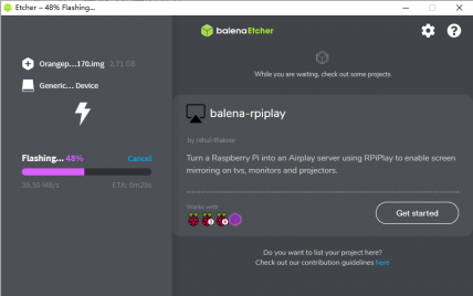
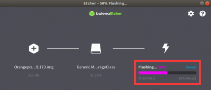
The interface displayed by balenaEtcher during burning Linux image is shown in the figure below. In addition, the progress bar is purple, indicating that the Linux image is being burned to the TF card.
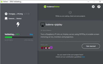
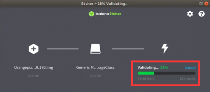
After the Linux image is burned, balenaEtcher will verify the image burned to the TF card by default to ensure that there are no problems in the burning process. As shown in the figure below, a green progress bar indicates that the image has been burned and balenaEtcher is verifying the burned image.
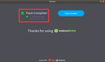
After the burning is completed successfully, the display interface of balenaEtcher is as shown in the figure below. If the green indicator icon is displayed, it means that the image is burned successfully. At this time, you can exit balenaEtcher, then pull out the TF card and insert it into the TF card slot of the development board for use.


How to use RKDevTool to burn Linux image to TF card
First, you need to prepare a good quality USB2.0 male-to-male data cable.
You also need to prepare a TF card with a capacity of 16GB or larger. The transmission speed of the TF card must be class10 or above. It is recommended to use a TF card from a brand such as SanDisk.
Then insert the TF card into the card slot of the development board.
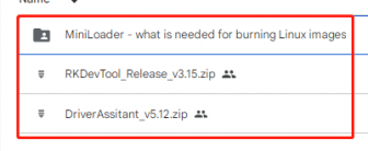
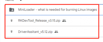
Then download Rockchip driver DriverAssitant_v5.12.zip and MiniLoader and burning tool RKDevTool_Release_v3.15.zip from Orange Pi's download page.
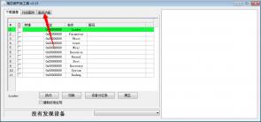
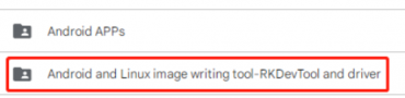
On the Orange Pi download page, first select the official tool, then go to the folder below.
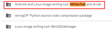
Then download all the files below.
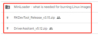
Note that the "MiniLoader-things needed for burning Linux images" folder is referred to as the MiniLoader folder below.
Then download the compressed file of the Linux operating system image file you want to burn from the Orange Pi data download page, and then use the decompression software to decompress it. Among the decompressed files, the file ending with ".img" is the image file of the operating system, and the size is generally more than 2GB.
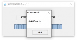
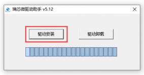
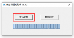
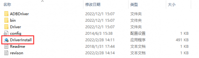
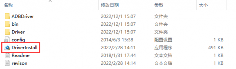
Then use the decompression software to decompress DriverAssitant_v5.12.zip, find the DriverInstall.exe executable file in the decompressed folder and open it.

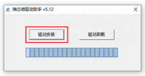
After opening DriverInstall.exe, the steps to install the Rockchip driver are as follows:
Click the "Driver Installation" button.

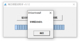
After waiting for a while, a window will pop up prompting "Driver installation successful", then click the "OK" button.
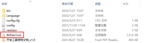
Then unzip RKDevTool_Release_v3.15.zip. This software does not need to be installed. Just find RKDevTool in the unzipped folder and open it.

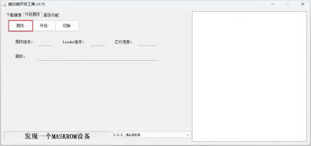
After opening the RKDevTool burning tool, because the computer has not yet connected to the development board via the USB2.0 male-to-male data cable, the lower left corner will prompt "No device found".
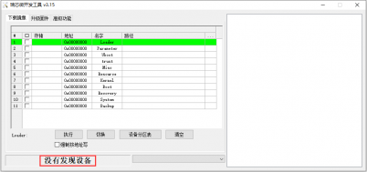
Then start burning the Linux image to the TF card.
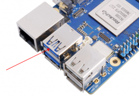
First, connect the development board to the Windows computer via a USB male-to-male data cable. The location of the USB burning port on the development board is shown in the figure below:
Then insert the TF card into the development board and make sure the development board is not connected to the power supply.
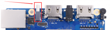
Then press and hold the MaskROM button on the development board. The location of the MaskROM button on the development board is shown in the figure below:

Then connect the development board to the power supply of the Type-C interface and power it on. Then you can release the MaskROM button.
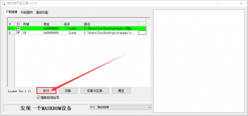
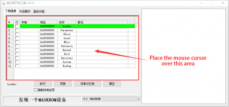
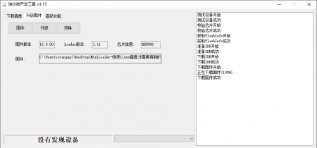
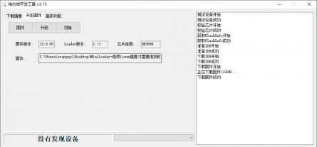
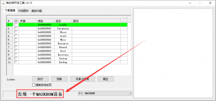
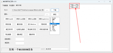
If the previous steps go smoothly, the development board will enter the MASKROM mode and the burning tool interface will prompt "A MASKROM device is found".

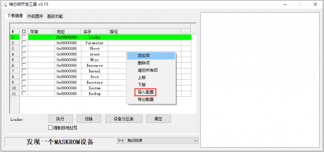
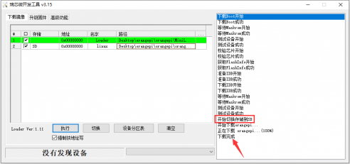
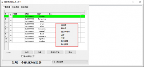
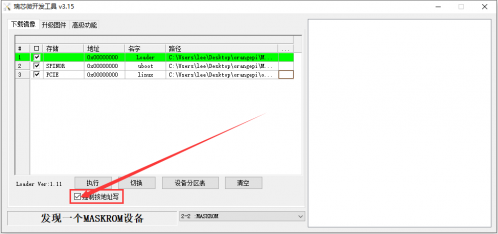
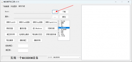
Then place the mouse cursor in the area below
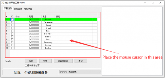
Then click the right button of the mouse to pop up the selection interface shown in the figure below.

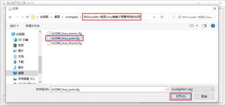
Then select the Import Configuration option.
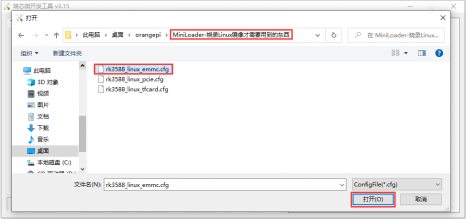
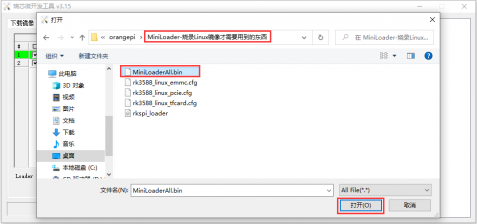
Then select the rk3588_linux_tfcard.cfg configuration file in the MiniLoader folder downloaded earlier, and then click Open.
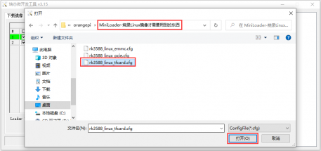
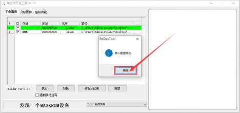
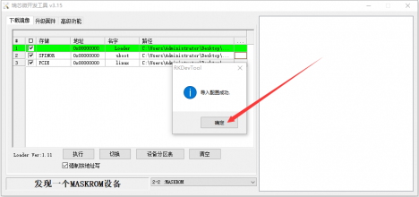
Then click OK.
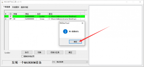
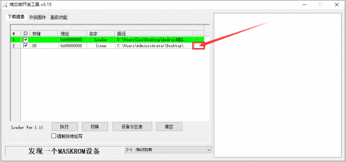
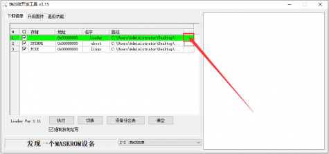
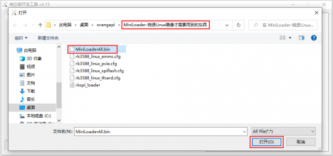
Then click the location shown in the picture below.
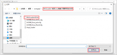
Select MiniLoaderAll.bin in the MiniLoader folder downloaded earlier, and then click Open.
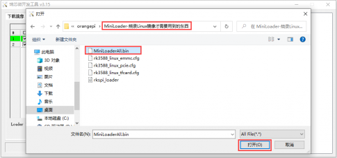
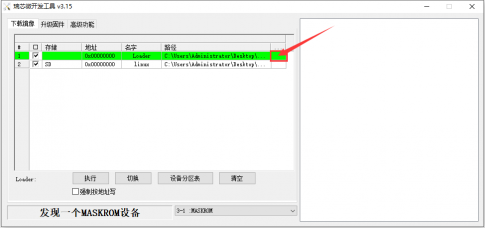
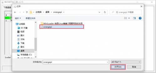
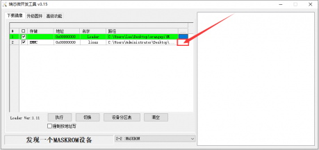
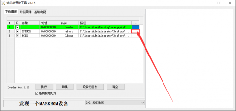
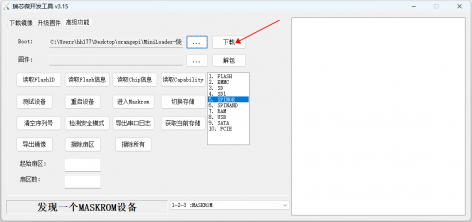
Then click the location shown in the picture below
Then select the path of the Linux image you want to burn, and click Open.
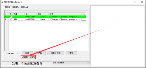
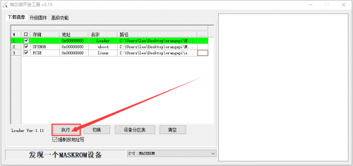
Before burning the image, it is recommended to rename the Linux image to be burned to orangepi.img or other shorter names, so that you can see the percentage value of the burning progress when burning the image.
Then please check the option of Force write by address.
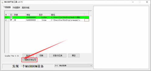
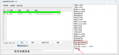
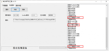
Click the execute button again to start burning the Linux image to the TF card of the development board.
The display log after the Linux image is burned is as shown below:
After burning the Linux image to the TF card, the Linux system will start automatically.


Method of burning Linux image to TF card based on Ubuntu PC
Note that the Linux image mentioned here specifically refers to the Linux distribution image such as Debian, Ubuntu, OpenWRT or OPi OS Arch downloaded from the Orange Pi data download page, and Ubuntu PC refers to a personal computer with Ubuntu system installed.
- First, prepare a TF card with a capacity of 16GB or larger. The transmission speed of the TF card must be class10 or above. It is recommended to use a TF card from a brand such as SanDisk.
- Then use the card reader to insert the TF card into the computer.
- Download balenaEtcher software from:
- After entering the balenaEtcher download page, click the green download button to jump to the software download location.
Then choose to download the Linux version of the software.
Download the compressed file of the Linux operating system image that you want to burn from the Orange Pi's download page, and then use decompression software to decompress it. In the decompressed file, the file ending with ".img" is the operating system image file, which is usually over 2GB in size.
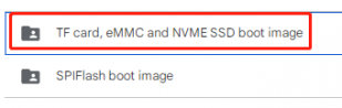
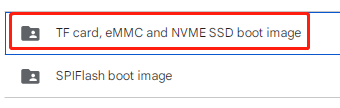
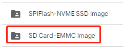
Note that if you are downloading an OpenWRT image, you will see the following two types of images in the OpenWRT image download link. Please select the image files in the "TF card, eMMC, and NVME SSD boot images" folder.
The decompression command for the compressed file ending in 7z is as follows:
test@test:~$ 7z x orangepi5ultra_1.0.0_debian_bullseye_desktop_xfce_linux5.10.160.7z
test@test:~$ ls orangepi5ultra_1.0.0_debian_bullseye_desktop_xfce_linux5.10.160.*
orangepi5ultra_1.0.0_debian_bullseye_desktop_xfce_linux5.10.160.7z orangepi5ultra_1.0.0_debian_bullseye_desktop_xfce_linux5.10.160.sha #校验和文件
orangepi5ultra_1.0.0_debian_bullseye_desktop_xfce_linux5.10.160.img #镜像文件
After decompressing the image, you can first use the sha256sum -c *.sha command to calculate if the checksum is correct. If the prompt is successful, it means that the downloaded image is correct and can be safely burned to the TF card. If the prompt is that the checksum does not match, it means that there is a problem with the downloaded image. Please try downloading it again.
test@test:~$ sha256sum -c *.sha
orangepi5ultra_1.0.0_debian_bullseye_desktop_xfce_linux5.10.160.img: OK
Then double-click balenaEtcher-1.5.109-x64.AppImage on the graphical interface of Ubuntu PC to open BalenaEtcher (no installation required). The interface displayed after opening balenaEtcher is shown in the following figure.
The specific steps for burning a Linux image using balenaEtcher are as follows:
Firstly, select the path of the Linux image file to be burned.
Then select the drive letter of the TF card.
Finally, clicking Flash will start burning the Linux image onto the TF card.
The interface displayed during the process of burning a Linux image by balenaEtcher is shown in the following figure. In addition, the progress bar displaying purple indicates that the Linux image is being burned to the TF card.


After the Linux image is burned, balenaEtcher will also verify the image burned to the TF card by default to ensure that there are no problems during the burning process. As shown in the following figure, a green progress bar indicates that the image has been burned and balenaEtcher is verifying the burned image.
After successful burning, the display interface of balenaEtcher is shown in the following figure. If a green indicator icon is displayed, it indicates that the image burning is successful. At this time, you can exit balenaEtcher, then unplug the TF card and insert it into the TF card slot of the development board for use.


Method for burning Linux images to eMMC
Method of burning Linux images to eMMC using RKDevTool
Note that all the following operations were performed on a Windows computer.
Note that the Linux image referred to here specifically refers to Linux distribution images such as Debian, Ubuntu, OpenWRT, or OPi OS Arch downloaded from the Orange Pi data download page.
The development board has reserved an expansion interface for the eMMC module. Before burning the system to eMMC, it is necessary to purchase an eMMC module that matches the eMMC interface of the development board. Then install the eMMC module onto the development board. The method of inserting the eMMC module into the development board is as follows:


We also need to prepare a high-quality USB 2.0 male to male data cable.

Then download the Rockchip micro driver DriverAssitant_v5.12.zip and MiniLoader, as well as the burning tool RKDevTool_Release_v3.15.zip, from the Orange Pi's download page.
On the Orange Pi download page, first select the official tool and then go to the folder below.
Then download all the files below.
Note that the "MiniLoader - What is needed to burn Linux images" folder is referred to as the MiniLoader folder in the following text.
Then download the compressed file of the Linux operating system image that you want to burn from the Orange Pi's download page, and use decompression software to decompress it. In the decompressed file, the file ending with ".img" is the operating system image file, which is usually over 2GB in size.
Then use decompression software to extract the DriverAssitant_v5.12.zip file, and find the DriverInstall.exe executable file in the extracted folder and open it.

The steps to install the Rockchip driver after opening DriverInstall.exe are as follows:
Click the 'Driver Installation' button.
After waiting for a period of time, a window will pop up prompting "Driver installation successful", and then click the "OK" button.

Then unzip RKDevTool_Release_v3.15.zip. This software does not need to be installed, just find RKDevTool in the decompressed folder and open it.
After opening the RKDevTool burning tool, the bottom left corner will prompt "Device not found" because the computer has not yet been connected to the development board through a USB 2.0 male to male data cable.

Then start burning the Linux image into eMMC.
Firstly, connect the development board to the Windows computer via a USB2.0 male to female data cable. The location of the USB burning port on the development board is shown in the following figure:
Ensure that the development board is not inserted with a TF card or connected to a power source.
Then hold down the MaskROM button on the development board and do not release it. The position of the MaskROM button on the development board is shown in the following figure:
Then connect the Type-C interface power to the development board, power it on, and then release the MaskROM button.
If the previous steps go smoothly, the development board will enter MASKROM mode, and the burning tool interface will prompt "Found a MASKROM device".

Then place the mouse cursor in the area below.
Then right-click and the selection interface shown in the following figure will pop up.
Then select the import configuration option.
Then select the rk3588_linux_emmc.cfg configuration file from the MiniLoader folder downloaded earlier, and click to open it.
Then click OK.
Then click on the position shown in the following image.
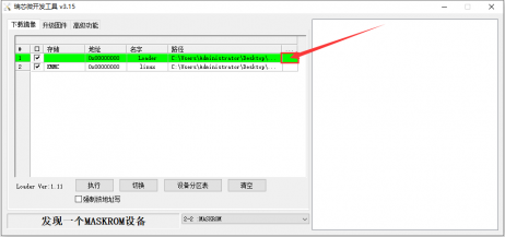
Select MiniLoaderAll.bin from the MiniLoader folder downloaded earlier, and then click Open.
Then click on the position shown in the following image.
Then select the path of the Linux image you want to burn, and click Open.
Before burning the image, it is recommended to rename the Linux image to orangepi.img or another shorter name, so that the percentage of burning progress can be seen when burning the image.
Then please check the option to force writing by address.
Clicking the execute button again will start burning the Linux image to the eMMC on the development board.

The display log after burning the linux image is shown in the following figure:
After burning the Linux image to eMMC, the linux system will automatically start.


Method of burning Linux images to eMMC using the dd command
Note that the Linux image referred to here specifically refers to Linux distribution images such as Debian, Ubuntu, OpenWRT, or OPi OS Arch downloaded from the Orange Pi data download page.
The development board has reserved an expansion interface for the eMMC module. Before burning the system to eMMC, it is necessary to purchase an eMMC module that matches the eMMC interface of the development board. Then install the eMMC module onto the development board. The method of inserting the eMMC module into the development board is as follows:
Burning a Linux image to eMMC using the dd command requires the use of a TF card, so the first step is to burn the Linux image onto the TF card, and then use the TF card to start the development board and enter the Linux system. The method of burning Linux images to TF cards can be found in the two sections of Burning Linux Images to TF Cards on Windows PC and Burning Linux Images to TF Cards on Ubuntu PC.
After starting the Linux system with a TF card, we first upload the decompressed Linux image file (downloaded from the official website as a Debian, Ubuntu, or OPi Arch image) to the TF card. Please refer to the instructions in the section on uploading Linux image files to the development board Linux system for the method of uploading files to the development board.
After uploading the image to the Linux system of the development board, we can enter the storage path of the image file in the command line of the Linux system of the development board. For example, I stored the Linux image of the development board in the /home/orangepi/Desktop directory, and then enter the /home/orangepi/Desktop directory to see the uploaded image file.
orangepi@orangepi:~$ cd /home/orangepi/Desktop
orangepi@orangepi:~/Desktop$ ls
orangepi5ultra_x.x.x_debian_bullseye_desktop_xfce_linux5.10.160.img
How to enter the command line of the Linux system on the development board?
- Please refer to the instructions in the Debugging Serial Port Usage section for the method of logging into the terminal using a serial port.
- Please refer to the instructions in the SSH Remote Login Development Board section for remote login to Linux systems using SSH.
- If HDMI, LCD or other display screens are connected, a command line terminal can be opened on the desktop.
Next, let's use the following command to confirm the device node of eMMC.
orangepi@orangepi:~/Desktop$ ls /dev/mmcblk*boot0 | cut -c1-12
/dev/mmcblk1
Then we can use the dd command to clear eMMC. Please note that after the of= parameter, please fill in the output of the command above.
orangepi@orangepi:~/Desktop$ sudo dd bs=1M if=/dev/zero of=/dev/mmcblk1 count=1000 status=progress
orangepi@orangepi:~/Desktop$ sudo sync
Then you can use the dd command to burn the Linux image of the development board to eMMC.
The if= parameter in the following command should be followed by the full path where the Linux image is stored and the name of the Linux image (such as /home/orangepi/Desktop/Linux image name). Because we have already entered the path of the Linux image, we only need to fill in the name of the Linux image.
Please do not copy the Linux image name in the following command, replace it with the actual image name (as the version number of the image may be updated).
sudo dd bs=1M if=orangepi5ultra_x.x.x_debian_bullseye_desktop_xfce_linux5.10.160.img of=/dev/mmcblk1 status=progress
sudo sync
Note that if you are uploading a compressed Linux image file ending in. 7z or. xz, please remember to decompress it before burning it with the dd command.
The detailed explanation and more usage of all parameters of the dd command can be viewed by executing the man dd command in a Linux system.
After successfully burning the linux image of the development board to eMMC, you can use the poweroff command to shut down. Then please unplug the TF card and press the power button briefly to start the linux system in eMMC.
Method for burning Linux images to SPIFlash+NVMe SSD
Note that the Linux image referred to here specifically refers to Linux distribution images such as Debian, Ubuntu, OpenWRT, or OPi OS Arch downloaded from the Orange Pi data download page.
Note that all the following operations were performed on a Windows computer.
Method of burning using RKDevTool
Firstly, it is necessary to prepare an NVMe SSD solid state drive with a PCIe interface specification of PCIe 3.0x4 for the M.2 slot of the development board.

Then insert the NVMe SSD into the M.2 PCIe interface of the development board and secure it in place.
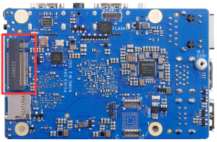
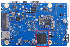
The position of SPI Flash on the development board is shown in the following figure, and no other settings are required before starting to burn.
Then you need to prepare a high-quality USB 2.0 male to male data cable.
Then download the Rockchip micro driver DriverAssitant_v5.12.zip and MiniLoader, as well as the burning tool RKDevTool_Release_v3.15.zip, from the Orange Pi's download page.
On the Orange Pi download page, first select the official tool and then go to the folder below.
Then download all the files below.
Note that the "MiniLoader - What is needed to burn Linux images" folder is referred to as the MiniLoader folder in the following text.
Then download the compressed file of the Linux operating system image that you want to burn from the Orange Pi's download page, and use decompression software to decompress it. In the decompressed file, the file ending with ".img" is the operating system image file, which is usually over 2GB in size.
Then use decompression software to extract the DriverAssitant_v5.12.zip file, and find the DriverInstall.exe executable file in the extracted folder and open it.

The steps to install the Rockchip driver after opening DriverInstall.exe are as follows:
Click the "Driver Installation" button.
After waiting for a period of time, a window will pop up prompting "Driver installation successful", and then click the "OK" button.
Then unzip RKDevTool_Release_v3.15.zip. This software does not need to be installed, just find RKDevTool in the decompressed folder and open it.

After opening the RKDevTool burning tool, the bottom left corner will prompt "Device not found" because the computer has not yet been connected to the development board through a USB2.0 male to male data cable.
Then start burning the Linux image onto the SSD.
Firstly, connect the development board to the Windows computer via a USB2.0 male to female data cable. The location of the USB burning port on the development board is shown in the following figure:
Ensure that the development board is not connected to a power source or inserted with a TF card.
Then hold down the MaskROM button on the development board and do not release it. The position of the MaskROM button on the development board is shown in the following figure:

Then connect the Type-C interface power to the development board, power it on, and then release the MaskROM button.
If the previous steps go smoothly, the development board will enter MASKROM mode, and the burning tool interface will prompt "Found a MASKROM device".
Then place the mouse cursor in the area below.
Then right-click and the selection interface shown in the following figure will pop up.
Then select the import configuration option.
Then enter the MiniLoader folder downloaded earlier, select the rk3588_linux_pcie.cfg configuration file, and click Open.
Then click OK.
Then click on the position shown in the following image.
Select MiniLoaderAll.bin from the MiniLoader folder downloaded earlier, and then click Open.
Then click on the position shown in the following image.
Then go to the MiniLoader folder that was downloaded earlier, select rkspi_loader.img, and click Open.
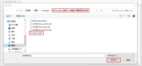
Then click on the position shown in the following image.
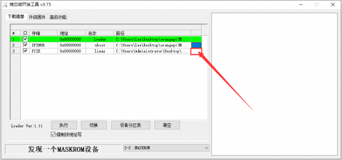
Then select the path of the linux image you want to burn, and click Open.
Before burning the image, it is recommended to rename the linux image to orangepi.img or another shorter name, so that the percentage of burning progress can be seen when burning the image.
Then please check the option to force writing by address.
Clicking the execute button again will start burning the linux image to the SSD.
The display log after burning the linux image is shown in the following figure:
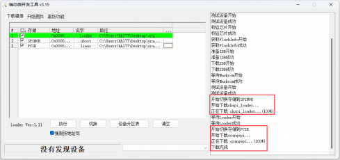
If there is a problem with burning, please clear SPIFlash first and then try burning again. Please refer to the instructions in the section on how to clear SPIFlash using RKDevTool.
After burning the image, the Linux system in SPIFlash+PCIe SSD will automatically start. If it does not start properly, please power it on again and try again.


Method of burning with dd command
Firstly, it is necessary to prepare an NVMe SSD solid state drive with a PCIe interface specification of PCIe 3.0x4 for the M.2 slot of the development board.
Then insert the NVMe SSD into the M.2 PCIe interface of the development board and secure it in place.
The position of SPI Flash on the development board is shown in the following figure, and no other settings are required before starting to burn.

Burning a linux image to a SPIFlash+NVMe SSD requires the use of a TF card, so the first step is to burn the linux image onto the TF card, and then use the TF card to boot the development board into the linux system. The method of burning a Linux image to a TF card can be found in the two sections: the method of burning a Linux image to a TF card based on Windows PC and the method of burning a Linux image to a TF card based on Ubuntu PC.
After starting the Linux system with a TF card, we first burn the u-boot image into SPI Flash.
First, run nand-sata-install. Ordinary users should remember to grant sudo privileges.
orangepi@orangepi:~$ sudo nand-sata-install
Then choose 7 Install/Update ther bootloader on SPI Flash。

- Then choose <Yes>。

- Then please be patient and wait for the burning to complete. After the burning is completed, the following will be displayed (a Done will appear in the bottom left corner):

There is no nand sata install script in the OPi OS Arch system. Please use the following command to mirror u-boot to SPI Flash:
[orangepi@orangepi ~]$ sudo dd if=/boot/rkspi_loader.img of=/dev/mtdblock0
Then upload the Linux image file (downloaded from the official website as a Debian, Ubuntu, or OpenWRT image) to the TF card. Please refer to the instructions in the section on uploading Linux image files to the development board Linux system for the method of uploading files to the development board.
Note that if you are downloading an OpenWRT image, you will see the following three types of images in the OpenWRT image download link. Please select the image files in the "TF card, eMMC, and NVME SSD boot images" folder.
After uploading the image to the linux system of the development board, we can enter the storage path of the image file in the command line of the linux system of the development board. For example, I stored the linux image of the development board in the /home/orangepi/Desktop directory, and then enter the /home/orangepi/Desktop directory to see the uploaded image file.
orangepi@orangepi:~$ cd /home/orangepi/Desktop
orangepi@orangepi:~/Desktop$ ls
orangepi5ultra_x.x.x_debian_bullseye_desktop_xfce_linux5.10.160.img
How to enter the command line of the Linux system on the development board?

- For the method of using the serial port to log in to the terminal, please refer to the instructions in the section on how to use the debugging serial port.
- Use ssh to remotely log in to the Linux system, please refer to the instructions in the section of SSH remote login to the development board.
- If HDMI, LCD or other display screens are connected, a command line terminal can be opened on the desktop.
Next, let's confirm that the NVMe SSD has been properly recognized by the Linux development board. If NVMe SSD recognizes it normally, you can use the sudo fdisk -l command to see nvme related information.
orangepi@orangepi:~/Desktop$ sudo fdisk -l | grep "nvme0n1"
Disk /dev/nvme0n1: 1.86 TiB, 2048408248320 bytes, 4000797360 sectors
Using the lspci command, you can see an NVMe related PCI device.
orangepi@orangepi:~/Desktop$ lspci
0004:40:00.0 PCI bridge: Fuzhou Rockchip Electronics Co., Ltd Device 3588 (rev 01)
0004:41:00.0 Non-Volatile memory controller: MAXIO Technology (Hangzhou) Ltd. NVMe SSD Controller MAP1202 (rev 01)
Then we can use the dd command to clear the NVMe SSD (optional).
orangepi@orangepi5ultra:~/Desktop$ sudo dd bs=1M if=/dev/zero of=/dev/nvme0n1 count=2000 status=progress
orangepi@orangepi5ultra:~/Desktop$ sudo sync
Then you can use the dd command to burn the linux image of the development board to the NVMe SSD.
The if= parameter in the following command should be followed by the full path where the Linux image is stored and the name of the Linux image (such as /home/orangepi/Desktop/Linux image name). Because we have already entered the path of the Linux image, we only need to fill in the name of the Linux image.
Please do not copy the linux image name in the following command, replace it with the actual image name (as the version number of the image may be updated).
sudo dd bs=1M if=orangepi5ultra_x.x.x_debian_bullseye_desktop_xfce_linux5.10.160.img of=/dev/nvme0n1 status=progress
sudo sync
Note that if you are uploading a compressed Linux image file ending in. 7z,. xz, or. gz, please remember to decompress it before burning it with the dd command.
The detailed explanation and more usage of all parameters of the dd command can be viewed by executing the man dd command in a Linux system.
After successfully burning the linux image of the development board to the NVMe SSD, you can use the poweroff command to shut down. Then please unplug the TF card and press the power button briefly to start the linux system in SPIFlash+NVMe SSD.
After starting the system in NVMe SSD, use the df -h command to see the actual hard drive capacity.
128GB NVMe SSD。
orangepi@orangepi:~$ df -h
Filesystem Size Used Avail Use% Mounted on
udev 3.8G 8.0K 3.8G 1% /dev
tmpfs 769M 1.4M 768M 1% /run
/dev/nvme0n1p2 118G 5.8G 111G 5% /
tmpfs 3.8G 0 3.8G 0% /dev/shm
tmpfs 5.0M 4.0K 5.0M 1% /run/lock
tmpfs 3.8G 16K 3.8G 1% /tmp
/dev/nvme0n1p1 256M 90M 166M 36% /boot
/dev/zram1 194M 9.9M 170M 6% /var/log
tmpfs 769M 60K 769M 1% /run/user/1000
tmpfs 769M 48K 769M 1% /run/user/0
2TB NVMe SSD。
orangepi@orangepi:~$ df -h
Filesystem Size Used Avail Use% Mounted on
udev 3.8G 8.0K 3.8G 1% /dev
tmpfs 769M 1.4M 768M 1% /run
/dev/nvme0n1p2 1.9T 4.1G 1.8T 1% /
tmpfs 3.8G 0 3.8G 0% /dev/shm
tmpfs 5.0M 4.0K 5.0M 1% /run/lock
/dev/zram2 3.7G 76K 3.5G 1% /tmp
/dev/nvme0n1p1 256M 90M 166M 36% /boot
/dev/zram1 194M 15M 165M 9% /var/log
tmpfs 769M 60K 769M 1% /run/user/1000
tmpfs 769M 48K 769M 1% /run/user/0
When the TF card and NVMe SSD burn the same system, if both the TF card and NVMe SSD are inserted in the development board, power on the development board and u-boot will start the system in the TF card first. However, since the systems in the TF card and the NVMe SSD are identical, the UUIDs of the /boot partition and the rootfs partition in the two storage devices are also the same. This may cause the partition in the NVMe SSD to be loaded when the TF card starts. Running the following script can solve this problem.
orangepi@orangepi:~$ sudo fix_mmc_ssd.sh
An identical system means that the image name is exactly the same. Even with the Debian11 system, different versions are different.
The fix_mmc_ssd.sh script is not available in the OPi OS Arch system.
Method of burning using balenaEtcher software
Please do not use this method for OPi OS Arch system and OpenWRT system.
Firstly, it is necessary to prepare an NVMe SSD solid state drive with a PCIe interface specification of PCIe 3.0x4 for the M.2 slot of the development board.
Then insert the NVMe SSD into the M.2 PCIe interface of the development board and secure it in place.
Please ensure that the development board has already been attached with SPI Flash. The location of SPI Flash on the development board is shown in the following figure, and no other settings are required before starting the burning process.
Burning a Linux image to a SPIFlash+NVMe SSD requires the use of a TF card, so the first step is to burn the Linux image onto the TF card, and then use the TF card to boot the development board into the Linux system. The method of burning a Linux image to a TF card can be found in the two sections: the method of burning a Linux image to a TF card based on Windows PC and the method of burning a Linux image to a TF card based on Ubuntu PC.
After booting into the Linux system on the TF card, please confirm that the NVMe SSD has been recognized by the Linux system on the development board. If NVMe SSD recognizes it normally, you can use the sudo fdisk -l command to see nvme related information.
orangepi@orangepi:~/Desktop$ sudo fdisk -l | grep "nvme0n1"
Disk /dev/nvme0n1: 1.86 TiB, 2048408248320 bytes, 4000797360 sectors
Using the lspci command, you can see an NVMe related PCI device.
orangepi@orangepi:~/Desktop$ lspci
0004:40:00.0 PCI bridge: Fuzhou Rockchip Electronics Co., Ltd Device 3588 (rev 01)
0004:41:00.0 Non-Volatile memory controller: MAXIO Technology (Hangzhou) Ltd. NVMe SSD Controller MAP1202 (rev 01)
balenaEtcher is already pre installed in the linux image, and the opening method is as follows:

If it is not pre installed, please refer to the instructions in the section on downloading and installing the arm64 version of balenaEtcher.
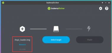
- The interface of balenaEtcher after opening is shown below:

The method of burning u-boot to SPI Flash on the development board using balenaEtcher is as follows:
- Firstly, open the balenaEtcher software and click on Flash from file.

- Then go to the /usr/lib/linux-u-boot-legacy-orangepi5ultra_1.0.0_arm64/ directory, select rkspi_loader.img, and click Open to open it.

The interface after opening rkspi_loader.img is shown below:
Then click on Select target.


- Then click on Show 2 hidden to open the option for more storage devices.

- Then select the device name /dev/mtdblock0 for SPI Flash, and click Select.

- Then click on Flash.

- Then click Yes, I’m sure。

- Then enter the password orangepi for the Linux system on the development board, and the u-boot image will be burned into SPI Flash.

- The display of the burning process is as follows:

- The display after burning is as follows:

The method of burning Linux system from TF card to NVMe SSD (this method is equivalent to cloning the system from TF card to NVMe SSD).
- First click Clone drive。

- Then select the device name /dev/mmcblk1 for the TF card.

- The interface after opening the TF card is shown below:

- Then click Select target。
- Then click on Show 2 hidden to open the option for more storage devices.
- Then select the device name /dev/nvme0n1 for NVMe SSD, and click Select.

- Then click Flash。

- Then click Yes, I’m sure。

- Then enter the password orangepi for the linux system on the development board, and the Linux image will be burned to the SSD.

- The display of the burning process is as follows:


- The display after burning is as follows:

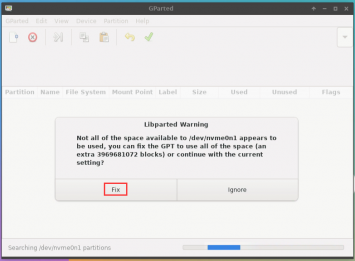
Then it is necessary to expand the capacity of the rootfs partition in the NVMe SSD, as follows:
Firstly, open GParted. If GParted is not pre installed on the system, please use the apt command to install it.
orangepi@orangepi:~$ sudo apt-get install -y gparted

- Then enter the linux system password orangepi, and click Authenticate.

Then click Fix。
Then click NVMe SSD。


- The display interface after selecting NVMe SSD is shown below:

- Then select the /dev/nvme0n1p2 partition, right-click, and choose Resize/Move.

Then drag the capacity to its maximum at the position shown in the figure below.
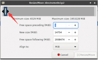
Then click Resize/Move。

Then click on the green √ in the position shown below
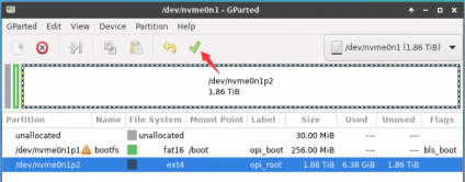
Then Click Apply。
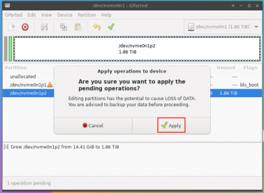
Then click Close to close it


- At this point, you can use the sudo poweroff command to shut down. Then please unplug the TF card and press the power button briefly to start the linux system in SPIFlash+NVMe SSD.
Step 9) is to clone the system from the TF card to the NMVe SSD. We can also directly burn the Linux image file to the NVMe SSD. Here are the general steps:
Upload the Linux image file to the Linux system on the development board.
Then use balenaEtcher to burn it.
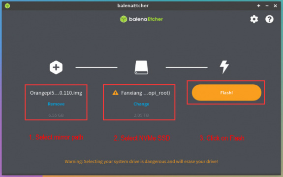
After burning the image using this method, there is no need to manually expand it. The first startup will automatically expand it.

Method for burning Linux images to SPIFlash+USB storage devices
Note that the Linux image referred to here specifically refers to Linux distribution images such as Debian, Ubuntu, OpenWRT, or OPi OS Arch downloaded from the Orange Pi data download page.
- Firstly, it is necessary to prepare a USB storage device, such as a USB flash drive.
- Then please refer to the instructions in two sections: the method of burning Linux images to TF cards based on Windows PC and the method of burning Linux images to TF cards based on Ubuntu PC to burn Linux images to USB storage devices. There is no difference between burning a Linux image to a USB storage device and burning a Linux image to a TF card (when the TF card is inserted into the card reader, the card reader is actually equivalent to a USB flash drive).
- Then insert the USB storage device that has burned the Linux system into the USB interface of the development board. Note that only the two USB 2.0 interfaces shown in the following figure support booting the Linux system, and the blue USB 3.0 interface does not support it.

The position of SPI Flash on the development board is shown in the following figure, and no other settings are required before starting to burn.
Burning the u-boot image to SPIFlash requires the use of a TF card, so the first step is to burn the Linux image onto the TF card, and then use the TF card to boot the development board into the Linux system. The method of burning a Linux image to a TF card can be found in the two sections: the method of burning a Linux image to a TF card based on Windows PC and the method of burning a Linux image to a TF card based on Ubuntu PC.
After starting the linux system with a TF card, you can burn the u-boot image to SPI Flash.
First, run nand-sata-install. Regular users should remember to grant sudo privileges
orangepi@orangepi:~$ sudo nand-sata-install
Then choose 7 Install/Update ther bootloader on SPI Flash。
- Then choose <Yes>。
- Then please be patient and wait for the burning to complete. After the burning is completed, the following will be displayed (a Done will appear in the bottom left corner):
There is no nand-sata-install script in the OPi OS Arch system. Please use the following command to mirror u-boot to SPI Flash:
[orangepi@orangepi ~]$ sudo dd if=/boot/rkspi_loader.img of=/dev/mtdblock0
At this point, you can use the poweroff command to shut down. Then please unplug the TF card and press the power button briefly to start the linux system in the SPIFlash+USB storage device.
After starting the system in the USB storage device, use the df -h command to see the actual capacity of the USB storage device.
orangepi@orangepi:~$ df -h
Filesystem Size Used Avail Use% Mounted on
udev 3.8G 8.0K 3.8G 1% /dev
tmpfs 769M 588K 769M 1% /run
/dev/sda2 15G 1.6G 13G 11% /
tmpfs 3.8G 0 3.8G 0% /dev/shm
tmpfs 5.0M 4.0K 5.0M 1% /run/lock
/dev/zram2 3.7G 60K 3.5G 1% /tmp
/dev/sda1 256M 111M 146M 44% /boot
/dev/zram1 194M 9.0M 171M 5% /var/log
tmpfs 769M 0 769M 0% /run/user/1000
Method of burning Android image to TF card
Method of burning using RKDevTool
Firstly, it is necessary to prepare a high-quality USB2.0 male to male data cable.
Then download the Rockchip driver DriverAssitant_v5.12.zip and the burning tool RKDevTool_Release_v3.15.zip from the Orange Pi's download page.
Then download the Android image from the Orange Pi's data download page. After opening the download link for the Android image, you can see the following two types of Android images. Please select the images in the TF card and eMMC startup image folders to download.
Then use decompression software to extract the DriverAssitant_v5.12.zip file, and find the DriverInstall.exe executable file in the extracted folder and open it.
The steps to install the Rockchip driver after opening DriverInstall.exe are as follows:
Click the "Driver Install" button.
After waiting for a period of time, a window will pop up prompting "Driver installation successful", and then click the "OK" button.
Then unzip RKDevTool_Release_v3.15.zip. This software does not need to be installed, just find RKDevTool in the decompressed folder and open it.
After opening the RKDevTool burning tool, because the computer has not yet been connected to the development board through a USB2.0 male to male data cable, the bottom left corner will prompt "Device not found"
Then start burning the Android image onto the TF card.
Firstly, connect the development board to the Windows computer via a USB2.0 male to female data cable. The location of the USB burning port on the development board is shown in the following figure:
Then insert the TF card into the development board and ensure that the board is not connected to a power source.
Then hold down the MaskROM button on the development board and do not release it. The position of the MaskROM button on the development board is shown in the following figure:
Then connect the Type-C interface power to the development board, power it on, and then release the MaskROM button.
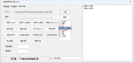
If the previous steps go smoothly, the development board will enter MASKROM mode, and the burning tool interface will prompt "Found a MASKROM device".
Then please select advanced features
Then click on the position shown in the following image.
Select MiniLoaderAll.bin from the MiniLoader folder downloaded earlier, and then click Open.
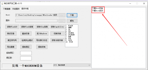
Then click on download
After downloading MiniLoaderAll.bin, the display is shown in the following figure:
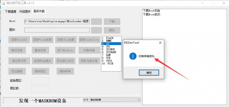
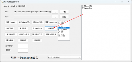
Then select the storage device as SD and click on switch storage.
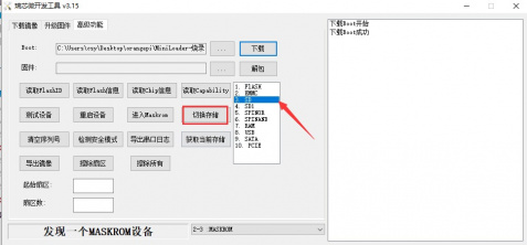
The display of successful switching is shown in the following figure:
Then click on the "Upgrade Firmware" section of the burning tool.
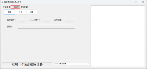
Then click the "Firmware" button to select the path of the Android image that needs to be burned.
Finally, clicking the "Upgrade" button will start burning, and the log during the burning process is shown in the following figure. After the burning is completed, the Android system will automatically start.


Method for burning Android images to eMMC
Method of burning using RKDevTool
Note that all the following operations were performed on a Windows computer.
The development board has reserved an extension interface for eMMC. Before burning the system to eMMC, it is necessary to purchase an eMMC module that matches the eMMC interface of the development board. Then install the eMMC module onto the development board.
The method of inserting the eMMC module into the development board is as follows:
We also need to prepare a high-quality USB 2.0 male to male data cable.
Then download the Rockchip driver DriverAssitant_v5.12.zip and the burning tool RKDevTool_Release_v3.15.zip from the Orange Pi's download page.
Then download the Android image from the Orange Pi's data download page. After opening the download link for the Android image, you can see the following two types of Android images. Please select the images in the TF card and eMMC startup image folders to download.
Then use decompression software to extract the DriverAssitant_v5.12.zip file, and find the DriverInstall.exe executable file in the extracted folder and open it.
The steps to install the Rockchip driver after opening DriverInstall.exe are as follows:
Click the 'Driver Installation' button.
After waiting for a period of time, a window will pop up prompting "Driver installation successful", and then click the "OK" button.
Then unzip RKDevTool_Release_v3.15.zip. This software does not need to be installed, just find RKDevTool in the decompressed folder and open it.
After opening the RKDevTool burning tool, the bottom left corner will prompt "Device not found" because the computer has not yet been connected to the development board through a USB2.0 male to male data cable.
Then start burning the Android image into eMMC.
Firstly, connect the development board to the Windows computer via a USB2.0 male to female data cable. The location of the USB burning port on the development board is shown in the following figure:
Ensure that the development board is not connected to a power source or inserted with a TF card.
Then hold down the MaskROM button on the development board and do not release it. The position of the MaskROM button on the development board is shown in the following figure:

Then connect the Type-C interface power to the development board, power it on, and then release the MaskROM button.
If the previous steps go smoothly, the development board will enter MASKROM mode, and the burning tool interface will prompt "Found a MASKROM device"
Then click on the "Upgrade Firmware" section of the burning tool.

Then click the "Firmware" button to select the path of the Android image that needs to be burned.
Then click the "Firmware" button to select the path of the Android image that needs to be burned.
Method for burning Android images to SPIFlash+NVMe SSD
Note that all the following operations were performed on a Windows computer.
First, you need to prepare an NVMe SSD solid state drive.
Then insert the NVMe SSD into the M.2 PCIe interface of the development board and secure it in place.
Please ensure that the development board has already been attached with SPI Flash. The location of SPI Flash on the development board is shown in the following figure, and no other settings are required before starting the burning process.
We also need to prepare a high-quality USB 2.0 male to male data cable.
Then download the Rockchip micro driver DriverAssitant_v5.12.zip and the burning tool RKDevTool_Release_v3.15.zip from the Orange Pi's download page.
Then download the Android image, open the download link for the Android image, and you will see the following two types of Android images. Please select the image in the SPIFlash-NVME SSD folder to download.

Then use decompression software to extract the DriverAssitant_v5.12.zip, and find the DriverInstall.exe executable file in the extracted folder and open it.
The steps to install the Rockchip driver after opening DriverInstall.exe are as follows:
Click the "Driver Installation" button.
After waiting for a period of time, a window will pop up prompting "Driver installation successful", and then click the "OK" button.
Then unzip RKDevTool_Release_v3.15.zip. This software does not need to be installed, just find RKDevTool in the decompressed folder and open it.

After opening the RKDevTool burning tool, the bottom left corner will prompt "Device not found" because the computer has not yet been connected to the development board through a USB 2.0 male to male data cable.
Then start burning the Android image to SPIFlash+NVMe SSD.
Firstly, connect the development board to the Windows computer via a USB2.0 male to female data cable. The location of the USB burning port on the development board is shown in the following figure:
Ensure that the development board is not inserted with a TF card or connected to a power source.
Then hold down the MaskROM button on the development board and do not release it. The position of the MaskROM button on the development board is shown in the following figure:
Then connect the Type-C interface power to the development board, power it on, and then release the MaskROM button.
If the previous steps go smoothly, the development board will enter MASKROM mode, and the burning tool interface will prompt "Found a MASKROM device".
Then click on the "Upgrade Firmware" section of the burning tool.
Then click the "Firmware" button to select the Android image that needs to be burned.
Finally, clicking the "Upgrade" button will start burning. The burning process is shown in the following figure. You can see that the firmware will first be burned to SPIFlash, and then burned to PCIE. After the burning is completed, the Android system will automatically start.

Method for burning Orange Pi OS (Droid) image to TF card
Note that all the following operations were performed on a Windows computer.
Firstly, prepare a TF card with a capacity of 8GB or higher, and the transfer speed of the TF card must be class10 or above. It is recommended to use TF cards from brands such as SanDisk.
Then use a card reader to insert the TF card into the computer
Then download the SDDiskTool burning tool from the Orange Pi's download page, ensuring that the SDDiskTool tool version is the latest v1.72.
Then download the image of Orange Pi OS (Droid) from the Orange Pi data download page.
Then use decompression software to extract the compressed file of the downloaded Orange Pi OS (Droid) image. In the decompressed file, the file ending with ".img" is the Orange Pi OS (Droid) image file, with a size of over 1GB.
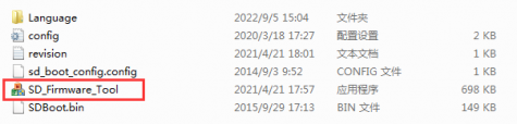
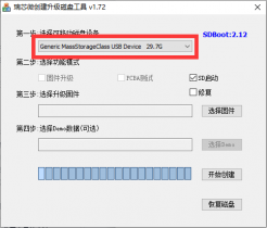
Then use decompression software to extract SDDiskTool_v1.72.zip. This software does not need to be installed. Simply find SD_Firmware_Tool.exe in the extracted folder and open it.
After opening SDDiskTool, if the TF card recognition is normal, the inserted disk device will be displayed in the "Select Removable Disk Device" column. Please make sure that the displayed disk device matches the drive letter of the TF card you want to burn. If it does not display, you can try unplugging the TF card.
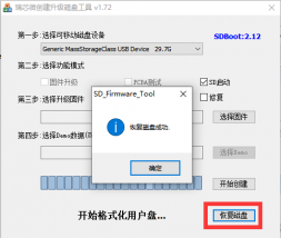
After confirming the drive letter, you can first format the TF card by clicking the recover disk button in SDDiskTool, or you can use the SD Card Formatter mentioned earlier to format the TF card.
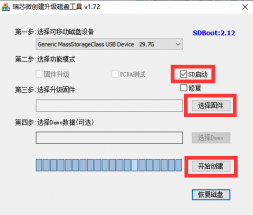
Then start writing the Orange Pi OS (Droid) image to the TF card.
First, check "SD Start" in the "Select Function Mode".
Then select the path of the Orange Pi OS (Droid) image in the "Choose Upgrade Firmware" column.
Finally, clicking the 'Start Creating' button will start burning the Orange Pi OS (Droid) image onto the TF card.
After burning, you can exit the SDDiskTool software and then unplug the TF card from the computer and insert it into the development board to start.


Burn Orange Pi OS (Droid) image to SPIFlash+NVMe SSD
Note that all the following operations were performed on a Windows computer.
First, you need to prepare an NVMe SSD solid state drive.
Then insert the NVMe SSD into the M.2 PCIe interface of the development board and secure it in place.
Please ensure that the development board has already been attached with SPI Flash. The location of SPI Flash on the development board is shown in the following figure, and no other settings are required before starting the burning process.
We also need to prepare a high-quality USB 2.0 male to male data cable.
Then download the Rockchip micro driver DriverAssitant_v5.12.zip from the Orange Pi's download page, and use the burning tool RKDevTool_Release_v3.15.zip.
Then download the image of Orange Pi OS (Droid).
Then use decompression software to extract the DriverAssitant_v5.12.zip file, and find the DriverInstall.exe executable file in the extracted folder and open it.
The steps to install the Ruixin micro driver after opening DriverInstall.exe are as follows:
Click the "Driver Installation" button.

After waiting for a period of time, a window will pop up prompting "Driver installation successful", and then click the "OK" button.

Then unzip RKDevTool_Release_v3.15.zip. This software does not need to be installed, just find RKDevTool in the decompressed folder and open it.

After opening the RKDevTool burning tool, the bottom left corner will prompt "Device not found" because the computer has not yet been connected to the development board through a USB 2.0 male to male data cable.
Then start burning the Orange Pi OS (Droid) image to SPIFlash+NVMe SSD.
Firstly, connect the development board to the Windows computer via a USB 2.0 male to female data cable. The location of the USB burning port on the development board is shown in the following figure:
Ensure that the development board is not inserted with a TF card or connected to a power source.
Then hold down the MaskROM button on the development board and do not release it. The position of the MaskROM button on the development board is shown in the following figure:

Then connect the Type-C interface power to the development board, power it on, and then release the MaskROM button.
If the previous steps go smoothly, the development board will enter MASKROM mode, and the burning tool interface will prompt "Found a MASKROM device".
Then click on the "Upgrade Firmware" section of the burning tool.
Then click the "Firmware" button to select the Orange Pi OS (Droid) image that needs to be burned.

Finally, clicking the "Upgrade" button will start burning. The burning process is shown in the following figure. You can see that the firmware will first be burned to SPIFlash, and then burned to PCIE. After the burning is completed, the Orange Pi OS (Droid) system will automatically start.
How to clear SPIFlash using RKDevTool
The location of SPI Flash on the development board is shown in the figure below:
First, you need to prepare a good quality USB2.0 male-to-male data cable.
Then download Rockchip driver DriverAssitant_v5.12.zip and MiniLoader and burning tool RKDevTool_Release_v3.15.zip from Orange Pi's download page.
On the Orange Pi download page, first select the official tool, then go to the folder below.
Then download all the files below.
Note that the "MiniLoader-things needed for burning Linux images" folder is referred to as the MiniLoader folder below.
Then use the decompression software to decompress DriverAssitant_v5.12.zip, then find the DriverInstall.exe executable file in the decompressed folder and open it.
After opening DriverInstall.exe, the steps to install the Rockchip driver are as follows:
Click the "Driver Installation" button.

After waiting for a while, a window will pop up prompting "Driver installation successful", then click the "OK" button.

Then unzip RKDevTool_Release_v3.15.zip. This software does not need to be installed. Just find RKDevTool in the unzipped folder and open it.

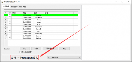
After opening the RKDevTool burning tool, because the computer has not yet connected to the development board via the USB2.0 male-to-male data cable, the lower left corner will prompt "No device found".
Then you can start clearing the contents in SPI FLASH.
First, connect the development board to the Windows computer via a USB2.0 male-to-male data cable. The location of the development board's USB interface is shown in the figure below:
Make sure the development board is not plugged into a TF card and is not connected to a power source.
Then press and hold the MaskROM button on the development board. The location of the MaskROM button on the development board is shown in the figure below:

Then connect the development board to the power supply of the Type-C interface and power it on. Then you can release the MaskROM button.
If the previous steps are successful, the development board will enter the MASKROM mode and the burning tool interface will prompt "A MASKROM device is found".
Then select Advanced Features.
Then click the location shown in the picture below.
Select MiniLoaderAll.bin in the MiniLoader folder downloaded earlier, and then click Open.
Then click Download.
After downloading MiniLoaderAll.bin, the display is as shown below:
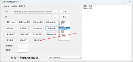
Then select the storage device as SPINOR.
Then click Switch Storage.
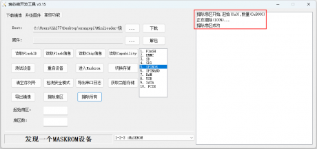
Then click Erase All to start erasing SPIFlash.
The display log after erasing SPIFlash is as follows:


Start the Orange Pi Development Board
- Insert the TF card with the image burned into the TF card slot of the Orange Pi development board. If the SPIFlash+NVMe SSD or eMMC module has been burned with the image, you do not need to insert the TF card. Just make sure that the NVMe SSD or eMMC module is properly inserted into the development board.
- The development board has an HDMI interface, which can be connected to a TV or HDMI monitor via an HDMI to HDMI cable. If you have purchased an LCD screen, you can also use it to display the system interface of the development board.
- Connect a USB mouse and keyboard to control the Orange Pi development board.
- The development board has an Ethernet port, which can be plugged into a network cable to access the Internet.
- Connect a high-quality power adapter with a 5V/4A or 5V/5A USB Type-C port.
Remember not to insert a power adapter with a voltage output greater than 5V, which will burn the development board.
Many unstable phenomena during the system power-on startup process are basically caused by power supply problems, so a reliable power adapter is very important. If you find that there is a phenomenon of continuous restart during the startup process, please replace the power supply or Type-C data cable and try again.
The Type-C power interface does not support PD negotiation.
In addition, please do not connect to the USB interface of the computer to power the development board.
Then turn on the power adapter. If everything is normal, you can see the system startup screen on the HDMI monitor or LCD screen.
If you want to view the system output information through the debug serial port, please use a serial cable to connect the development board to the computer. For the serial port connection method, please refer to the section "How to use the debug serial port".
How to use the debug serial port
Connection Instructions for Debug Serial Port
First, you need to prepare a 3.3V USB to TTL module, and then insert the USB interface of the USB to TTL module into the USB interface of the computer.
For better compatibility, it is recommended to use the CH340 USB to TTL module. Please do not use the CP2102 or PL2303 type USB to TTL modules.
Before purchasing a USB to TTL module, please confirm that the module supports a baud rate of 1500000.

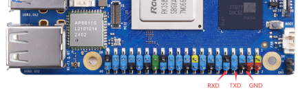
The corresponding relationship between the debugging serial port GND, RXD and TXD pins of the development board is shown in the figure below:
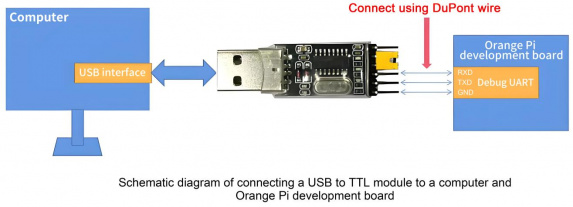
The GND, TXD and RXD pins of the USB to TTL module need to be connected to the debug serial port of the development board through DuPont cables.
Connect the GND of the USB to TTL module to the GND of the development board.
Connect the RX of the USB to TTL module to the TX of the development board.
Connect the TX of the USB to TTL module to the RX of the development board.
The schematic diagram of connecting the USB to TTL module to the computer and the Orange Pi development board is as follows:
The TX and RX of the serial port need to be cross-connected. If you don't want to carefully distinguish the order of TX and RX, you can connect the TX and RX of the serial port randomly. If there is no output in the test, then swap the order of TX and RX. In this way, there will always be one order that is correct.


How to use the debug serial port on Ubuntu platform
There are many serial port debugging software that can be used under Linux, such as putty, minicom, etc. The following demonstrates how to use putty.
First, insert the USB to TTL module into the USB port of the Ubuntu computer. If the USB to TTL module is connected and recognized normally, you can see the corresponding device node name under /dev of the Ubuntu PC. Remember this node name, which will be used when setting up the serial port software later.
test@test:~$ ls /dev/ttyUSB*
/dev/ttyUSB0
Then install putty on your Ubuntu PC using the command below.
test@test:~$ sudo apt-get update
test@test:~$ sudo apt-get install -y putty
Then run putty and remember to add sudo permissions.
test@test:~$ sudo putty
After executing the putty command, the following interface will pop up.
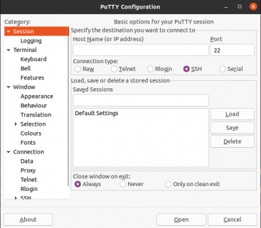
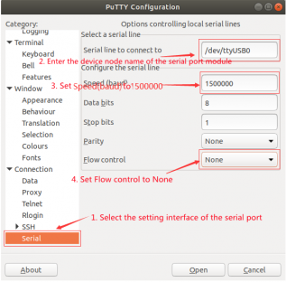
First select the serial port settings interface.
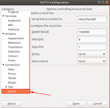
Then set the parameters of the serial port.
Set Serial line to connect to to /dev/ttyUSB0 (change to the corresponding node name, usually /dev/ttyUSB0).
Set Speed(baud) to 1500000 (the baud rate of the serial port).
Set Flow control to None.
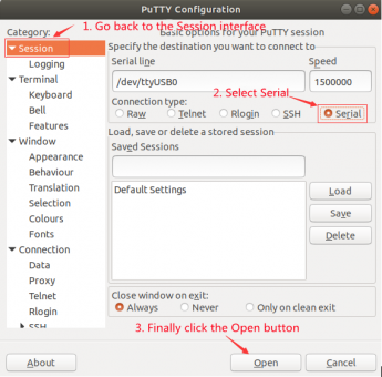
After completing the settings on the serial port settings interface, return to the Session interface.
First select Connection type as Serial.
Then click the Open button to connect the serial port.
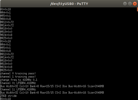
After starting the development board, you can see the log information output by the system from the opened serial port terminal.


How to use the debug serial port on Windows platform
There are many serial port debugging software that can be used under Windows, such as SecureCRT, MobaXterm, etc. The following demonstrates how to use MobaXterm. This software has a free version and can be used without purchasing a serial number.
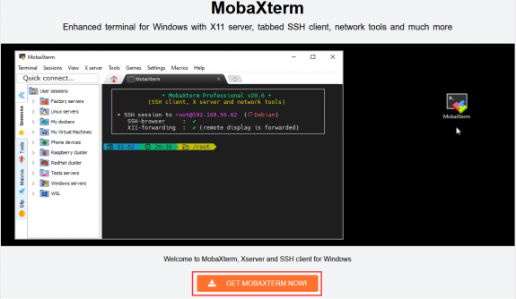
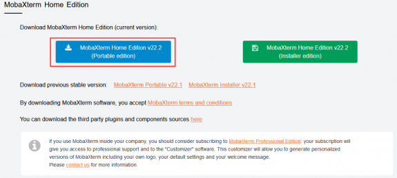
Download MobaXterm.
Download MobaXterm from the following URL:
to the MobaXterm download page and click GET XOBATERM NOW!.
Then choose to download the Home version.

Then select the Portable version. After downloading, you don’t need to install it. You can use it directly by opening it.
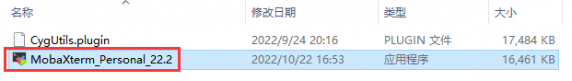
After downloading, use decompression software to decompress the downloaded compressed package to get the executable software of MobaXterm, and then double-click to open it.
After opening the software, the steps to set up the serial port connection are as follows:
Open the session settings interface.
Select the serial port type.
Select the serial port number (select the corresponding port number according to the actual situation). If you cannot see the port number, please use 360 Driver Master to scan and install the USB to TTL serial port chip driver.
Select the serial port baud rate as 1500000.
Finally, click the "OK" button to complete the settings.


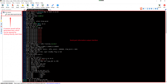
Click the "OK" button to enter the following interface. Now start the development board and you can see the output information of the serial port.

Power supply instructions using the 5V pin in the 40pin interface of the development board
The power supply method we recommend for the development board is to use a 5V/5A Type C interface power cord plugged into the Type-C power interface of the development board for power supply. If you need to use the 5V pin in the 40pin interface to power the development board, please make sure that the power cord and power adapter used can meet the power supply requirements of the development board. If there is any unstable use, please switch back to Type-C power supply.
First, you need to prepare a power cord as shown in the figure below.

The power cord shown in the picture above can be purchased on Amazon or Aliexpress. Please search and purchase it by yourself.
Use the 5V pin in the 40-pin interface to power the development board. The power line connection is as follows:
The USB A port of the power cable shown in the figure above needs to be plugged into the 5V/5A power adapter connector (please do not plug it into the USB port of the computer for power supply).
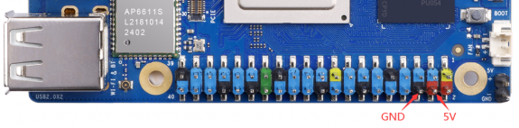
The red DuPont cable needs to be plugged into the 5V pin of the 40pin of the development board.
The black DuPont cable needs to be plugged into the GND pin of the 40pin interface.
The positions of the 5V pin and GND pin of the 40pin interface in the development board are shown in the figure below. Remember not to connect them in reverse.


Instructions for using Ubuntu/Debian Server and Xfce desktop system
This chapter is based on the Linux server version image and the Xfce desktop version image.
If you are using the OPi OS Arch image, please refer to the Orange Pi OS Arch system usage instructions chapter.
Supported Linux image types and kernel versions
| Linux Image Type | Kernel version | Server Edition | Desktop version |
| Debian 11 - Bullseye | Linux5.10 | Support | Support |
| Debian 12 - Bookworm | Linux5.10 | Support | Support |
| Ubuntu 20.04 - Focal | Linux5.10 | Support | Support |
| Ubuntu 22.04 - Jammy | Linux5.10 | Support | Support |
| Debian 12 - Bookworm | Linux6.1 | Support | Support |
| Ubuntu 22.04 - Jammy | Linux6.1 | Support | Support |
3.2. Linux 5.10 system compatibility
| Function | Debian11 | Debian12 | Ubuntu20.04 | Ubuntu22.04 |
| HDMI TX Video | OK | OK | OK | OK |
| HDMI TX Audio | OK | OK | OK | OK |
| HDMI RX Video | OK | OK | OK | OK |
| HDMI RX Audio | OK | OK | OK | OK |
| USB2.0x2 | OK | OK | OK | OK |
| USB3.0x2 | OK | OK | OK | OK |
| 2.5G network port | OK | OK | OK | OK |
| Network port light | OK | OK | OK | OK |
| WIFI | OK | OK | OK | OK |
| Bluetooth | OK | OK | OK | OK |
| Debug serial port | OK | OK | OK | OK |
| RTC chip | OK | OK | OK | OK |
| FAN Fan Connector | OK | OK | OK | OK |
| eMMC interface | OK | OK | OK | OK |
| GPIO(40pin) | OK | OK | OK | OK |
| UART(40pin) | OK | OK | OK | OK |
| SPI(40pin) | OK | OK | OK | OK |
| I2C(40pin) | OK | OK | OK | OK |
| CAN(40pin) | OK | OK | OK | OK |
| PWM(40pin) | OK | OK | OK | OK |
| OV13850 Camera | OK | OK | OK | OK |
| OV13855 Camera | OK | OK | OK | OK |
| SPI+NVME Start | OK | OK | OK | OK |
| LCD | OK | OK | OK | OK |
| MIC | OK | OK | OK | OK |
| Headphone playback | OK | OK | OK | OK |
| Headphone Recording | OK | OK | OK | OK |
| Three-color LED light | OK | OK | OK | OK |
| GPU | OK | OK | OK | OK |
| NPU | OK | OK | OK | OK |
| VPU | OK | OK | OK | OK |
| Power button | OK | OK | OK | OK |
| Watchdog test | OK | OK | OK | OK |
| Chromium hard decoding video | OK | OK | OK | OK |
Linux 6.1 system compatibility
| Function | Debian12 | Ubuntu22.04 |
| HDMI TX Video | OK | OK |
| HDMI TX Audio | OK | OK |
| HDMI RX Video | OK | OK |
| HDMI RX Audio | OK | OK |
| USB2.0 x 2 | OK | OK |
| USB3.0 x 2 | OK | OK |
| Gigabit Ethernet | OK | OK |
| Network port status light | OK | OK |
| WIFI | OK | OK |
| Bluetooth | OK | OK |
| Debug serial port | OK | OK |
| RTC chip | OK | OK |
| FAN Fan Connector | OK | OK |
| eMMC interface | OK | OK |
| GPIO(40pin) | OK | OK |
| UART(40pin) | OK | OK |
| SPI(40pin) | OK | OK |
| I2C(40pin) | OK | OK |
| CAN(40pin) | NO | NO |
| PWM(40pin) | OK | OK |
| OV13850 Camera | OK | OK |
| OV13855 Camera | OK | OK |
| SPI+NVME Start | OK | OK |
| LCD | OK | OK |
| MIC | OK | OK |
| Headphone playback | OK | OK |
| Headphone Recording | OK | OK |
| Three-color LED light | OK | OK |
| GPU | OK | OK |
| NPU | OK | OK |
| VPU | OK | OK |
| Power button | OK | OK |
| Watchdog test | OK | OK |
| Chromium hard decoding video | OK | OK |
Linux command format description in this manual
All commands in this manual that need to be entered in the Linux system will be framed with the following boxes.
As shown below, the contents in the yellow box indicate the contents that require special attention, except for the commands inside.
Description of the prompt type before the command.
The prompt before the command refers to the content in the red box below. This part is not part of the Linux command, so when entering a command in the Linux system, please do not enter the content in red font.
orangepi@orangepi:~$ sudo apt update
root@orangepi:~# vim /boot/boot.cmd
test@test:~$ ssh root@192.168.1.xxx
root@test:~# ls
root@orangepi:~$ The prompt indicates that this command is entered in the Linux system of the development board. The $ at the end of the prompt indicates that the current user of the system is a common user. When executing privileged commands, sudo is required.
root@orangepi:~# The prompt indicates that this command is entered in the Linux system of the development board. The # at the end of the prompt indicates that the current user of the system is the root user and can execute any command he wants.
test@test:~$ The prompt indicates that this command is entered in an Ubuntu PC or Ubuntu virtual machine, not in the Linux system of the development board. The $ at the end of the prompt indicates that the current user of the system is a normal user. When executing privileged commands, sudo needs to be added.
root@test:~# The prompt indicates that this command is entered in an Ubuntu PC or Ubuntu virtual machine, not in the Linux system of the development board. The # at the end of the prompt indicates that the current user of the system is the root user and can execute any command you want.
What are the commands that need to be entered?
As shown below, the bold black part is the command that needs to be entered, and the content below the command is the output (some commands have output, some may not). This part does not need to be entered.
root@orangepi:~# cat /boot/orangepiEnv.txt
verbosity=7
bootlogo=false
console=serial
As shown below, some commands cannot fit in one line and will be placed on the next line. The bold black parts are the commands that need to be entered. When these commands are entered on one line, the "\" at the end of each line needs to be removed, as it is not part of the command. In addition, there are spaces between different parts of the command, so please do not miss them.
orangepi@orangepi:~$ echo \
"deb [arch=$(dpkg --print-architecture) \
signed-by=/usr/share/keyrings/docker-archive-keyring.gpg] \
https://download.docker.com/linux/debian \
$(lsb_release -cs) stable" | sudo tee /etc/apt/sources.list.d/docker.list > /dev/null
Linux system login instructions
3.5.1.Linux system default login account and password
| Account | Password |
| root | orangepi |
| orangepi | orangepi |
Please note that when you enter the password, the specific content of the password will not be displayed on the screen. Please do not think that there is any malfunction. Just press Enter after entering it.
If you get an error message when entering the password, or there is a problem with the ssh connection, please note that as long as you are using the Linux image provided by Orange Pi, do not doubt that the password above is incorrect, but look for other reasons.
3.5.2. How to set up automatic login for Linux system terminal
The Linux system automatically logs in to the terminal by default, and the default login username is orangepi.
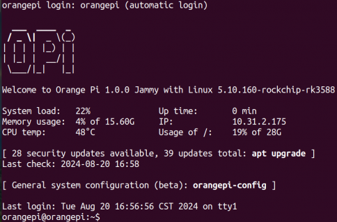
Use the following command to set the root user to automatically log in to the terminal.
orangepi@orangepi:~$ sudo auto_login_cli.sh root
Use the following command to disable automatic login to the terminal.
orangepi@orangepi:~$ sudo auto_login_cli.sh -d
Use the following command to set the orangepi user to automatically log in to the terminal again.
orangepi@orangepi:~$ sudo auto_login_cli.sh orangepi

Linux desktop system automatic login instructions
After the desktop version system is started, it will automatically log in to the desktop without entering a password.

Run the following command to prevent the desktop version of the system from automatically logging into the desktop.
orangepi@orangepi:~$ sudo disable_desktop_autologin.sh
Then restart the system and a login dialog box will appear. You need to enter the password to enter the system.
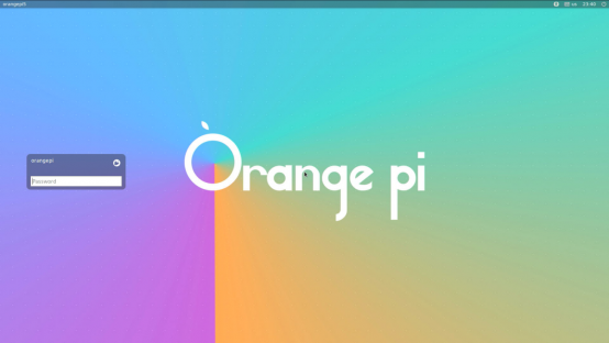


How to set up automatic login for root user in Linux desktop system
Execute the following command to set the desktop system to automatically log in as root user
orangepi@orangepi:~$ sudo desktop_login.sh root
Then restart the system and the root user will automatically log in to the desktop.
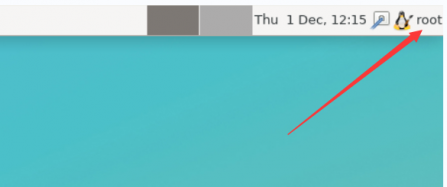
Note that if you log in to the desktop system as root, you cannot use pulseaudio in the upper right corner to manage audio devices.
Also, please note that this is not a bug, because pulseaudio is not allowed to run under the root user.
Run the following command to set the desktop system to automatically log in using the orangepi user again.
orangepi@orangepi:~$ sudo desktop_login.sh orangepi

How to disable the desktop in Linux desktop system
First enter the following command in the command line. Please remember to add sudo permissions.
orangepi@orangepi:~$ sudo systemctl disable lightdm.service
Then restart the Linux system and you will find that the desktop will not be displayed.
orangepi@orangepi:~$ sudo reboot
The steps to reopen the desktop are as follows:
First enter the following command in the command line. Please remember to add sudo permissions.
orangepi@orangepi:~$ sudo systemctl start lightdm.service
orangepi@orangepi:~$ sudo systemctl enable lightdm.service
After selecting, the monitor will display the desktop
Onboard LED light test instructions
There is a red, green and blue light on the development board, and its location is shown in the figure below:
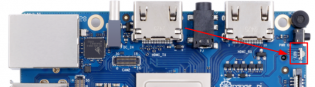
As long as the development board is powered on, the red LED light will be always on. This is controlled by hardware and cannot be turned off by software. The red LED light can be used to determine whether the power of the development board has been turned on normally.
The green and blue LED lights will keep flashing after the kernel starts, which is controlled by software.
The method of setting the green light on and off and flashing is as follows:
Note: The following operations must be performed as the root user.
First enter the Green Light settings directory.
root@orangepi:~# cd /sys/class/leds/green_led
The command to set the green light to stop flashing is as follows:
root@orangepi:/sys/class/leds/green_led# echo none > trigger
The command to set the green light to always be on is as follows:
root@orangepi:/sys/class/leds/green_led# echo default-on > trigger
The command to set the green light to flash is as follows:
root@orangepi:/sys/class/leds/green_led# echo heartbeat > trigger
The method of using commands to set the blue light on and off and flashing is as follows:
Note: The following operations must be performed as the root user.
First enter the settings directory of Lantern.
root@orangepi:~# cd /sys/class/leds/blue_led
The command to set the blue light to stop flashing is as follows:
root@orangepi:/sys/class/leds/blue_led# echo none > trigger
The command to set the blue light to always be on is as follows:
root@orangepi:/sys/class/leds/blue_led# echo default-on > trigger
The command to set the blue light to flash is as follows:
root@orangepi:/sys/class/leds/blue_led# echo heartbeat > trigger
If you do not need the LED light to flash after powering on, you can use the following method to turn off the green and blue lights.
First run orangepi-config. Remember to add sudo permissions as a normal user.
orangepi@orangepi:~$ sudo orangepi-config
Then select System.

Then select Hardware.
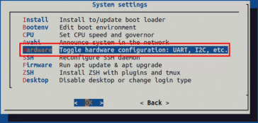
Then use the arrow keys on your keyboard to locate the position shown in the figure below, and then use the space bar to select the opi5ultra-disable-leds configuration.

Then select <Save> to save.
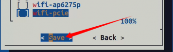
Then select <Back>.
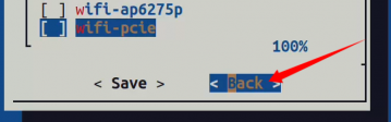
Then select <Reboot> to restart the system to make the configuration take effect.
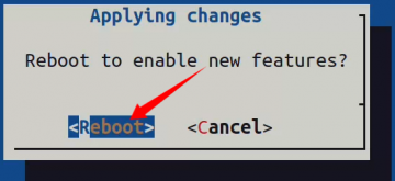
After restarting, you can see that only the red light on the development board is always on, and the green and blue lights will not flash.


Network connection test
Ethernet port test
First, plug one end of the network cable into the Ethernet port of the development board, and the other end of the network cable into the router, and make sure the network is unobstructed.
After the system starts, the IP address will be automatically assigned to the Ethernet card through DHCP, and no other configuration is required.
The command to check the IP address in the Linux system of the development board is as follows:
orangepi@orangepi:~$ ip addr show
1: lo: <LOOPBACK,UP,LOWER_UP> mtu 65536 qdisc noqueue state UNKNOWN group default qlen 1000
link/loopback 00:00:00:00:00:00 brd 00:00:00:00:00:00
inet 127.0.0.1/8 scope host lo
valid_lft forever preferred_lft forever
inet6 ::1/128 scope host
valid_lft forever preferred_lft forever
2: enP3p49s0: <BROADCAST,MULTICAST,UP,LOWER_UP> mtu 1500 qdisc mq state UP group default qlen 1000
link/ether 00:e0:4c:68:00:0f brd ff:ff:ff:ff:ff:ff
inet 10.31.2.249/16 brd 10.31.255.255 scope global dynamic noprefixroute enP3p49s0
valid_lft 42670sec preferred_lft 42670sec
inet6 fe80::d5aa:9a6:cd41:942e/64 scope link noprefixroute
valid_lft forever preferred_lft forever
3: wlan0: <NO-CARRIER,BROADCAST,MULTICAST,UP,LOWER_UP> mtu 1500 qdisc fq_codel state DORMANT group default qlen 1000
link/ether 50:41:1c:f1:0f:7e brd ff:ff:ff:ff:ff:ff
When using ifconfig to check the IP address, if the following message is displayed, it is because sudo is not added. The correct command is: sudo ifconfig.
orangepi@orangepi:~$ ifconfig
Command 'ifconfig' is available in the following places
* /sbin/ifconfig
* /usr/sbin/ifconfig
The command could not be located because '/sbin:/usr/sbin' is not included in the PATH environment variable.
This is most likely caused by the lack of administrative privileges associated with your user account.
ifconfig: command not found
There are three ways to check the IP address after the development board is started:
1. Connect an HDMI display, then log in to the system and use the ip addr show command to view the IP address.
2. Enter the ip addr show command in the debug serial port terminal to view the IP address.
3. If there is no debug serial port and no HDMI display, you can also view the IP address of the development board network port through the router's management interface. However, this method often causes some people to be unable to see the IP address of the development board normally. If you can't see it, the debugging method is as follows:
A) First check whether the Linux system has started normally. If the three-color light on the development board is flashing, it is generally started normally. If only the red light is on, it means that the system has not started normally;
B) Check whether the network cable is plugged in tightly, or try another network cable;
C) Try another router (there are many problems with routers, such as the router cannot allocate IP addresses normally, or the IP address has been allocated normally but cannot be seen in the router);
D) If there is no router to replace, you can only connect an HDMI display or use the debug serial port to view the IP address.
It should also be noted that the development board DHCP automatically assigns IP addresses without any settings.
The command to test network connectivity is as follows. The ping command can be interrupted by pressing the Ctrl+C shortcut key.
orangepi@orangepi:~$ ping www.baidu.com -I enP3p49s0
PING www.a.shifen.com (183.2.172.185) from 10.31.2.249 enP3p49s0: 56(84) bytes of data.
64 bytes from 183.2.172.185 (183.2.172.185): icmp_seq=1 ttl=53 time=39.5 ms
64 bytes from 183.2.172.185 (183.2.172.185): icmp_seq=2 ttl=53 time=33.1 ms
64 bytes from 183.2.172.185 (183.2.172.185): icmp_seq=3 ttl=53 time=32.4 ms
64 bytes from 14.215.177.38 (14.215.177.38): icmp_seq=4 ttl=56 time=7.27 ms
^C
--- www.a.shifen.com ping statistics ---
4 packets transmitted, 4 received, 0% packet loss, time 3002ms
rtt min/avg/max/mdev = 6.260/6.770/7.275/0.373 ms
WIFI connection test
Please do not connect to WIFI by modifying the /etc/network/interfaces configuration file. This method may cause problems when connecting to the WIFI network.
Server version image connects to WIFI through command
When the development board is not connected to Ethernet, not connected to HDMI display, and only connected to the serial port, it is recommended to use the command demonstrated in this section to connect to the WIFI network. Because nmtui can only display characters in some serial port software (such as minicom), it cannot display the graphical interface normally. Of course, if the development board is connected to Ethernet or HDMI display, you can also use the command demonstrated in this section to connect to the WIFI network.
Log in to the Linux system first. There are three ways:
If the development board is connected to the network cable, you can log in to the Linux system remotely through SSH.
If the development board is connected to the debug serial port, you can use the serial terminal to log in to the Linux system.
If the development board is connected to the HDMI display, you can log in to the Linux system through the HDMI display terminal.
First use the nmcli dev wifi command to scan the surrounding WIFI hotspots.
orangepi@orangepi:~$ nmcli dev wifi
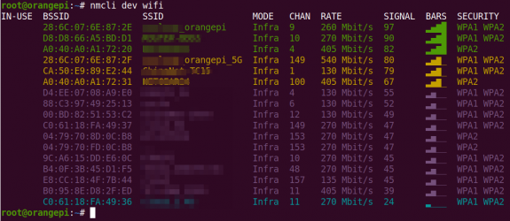
Then use the nmcli command to connect to the scanned WIFI hotspot, where:
wifi_name needs to be replaced with the name of the WIFI hotspot you want to connect to.
wifi_passwd needs to be replaced with the password of the WIFI hotspot you want to connect to.
orangepi@orangepi:~$ sudo nmcli dev wifi connect wifi_name password wifi_passwd
Device 'wlan0' successfully activated with 'cf937f88-ca1e-4411-bb50-61f402eef293'.
Use theip addr show wlan0 command to view the IP address of the wifi.
orangepi@orangepi:~$ ip addr show wlan0
11: wlan0: <BROADCAST,MULTICAST,UP,LOWER_UP> mtu 1500 qdisc pfifo_fast state UP group default qlen 1000
link/ether 23:8c:d6:ae:76:bb brd ff:ff:ff:ff:ff:ff
inet 192.168.1.11/24 brd 192.168.1.255 scope global dynamic noprefixroute wlan0
valid_lft 259192sec preferred_lft 259192sec
inet6 240e:3b7:3240:c3a0:c401:a445:5002:ccdd/64 scope global dynamic noprefixroute
valid_lft 259192sec preferred_lft 172792sec
inet6 fe80::42f1:6019:a80e:4c31/64 scope link noprefixroute
valid_lft forever preferred_lft forever
Use the ping command to test the connectivity of the WiFi network. The ping command can be interrupted by pressing the Ctrl+Cshortcut key.
orangepi@orangepi:~$ ping www.orangepi.org -I wlan0
PING www.orangepi.org (182.92.236.130) from 192.168.1.49 wlan0: 56(84) bytes of data.
64 bytes from 182.92.236.130 (182.92.236.130): icmp_seq=1 ttl=52 time=43.5 ms
64 bytes from 182.92.236.130 (182.92.236.130): icmp_seq=2 ttl=52 time=41.3 ms
64 bytes from 182.92.236.130 (182.92.236.130): icmp_seq=3 ttl=52 time=44.9 ms
64 bytes from 182.92.236.130 (182.92.236.130): icmp_seq=4 ttl=52 time=45.6 ms
64 bytes from 182.92.236.130 (182.92.236.130): icmp_seq=5 ttl=52 time=48.8 ms
^C
--- www.orangepi.org ping statistics ---
5 packets transmitted, 5 received, 0% packet loss, time 4006ms
rtt min/avg/max/mdev = 41.321/44.864/48.834/2.484 ms

The server version image connects to WIFI through a graphical method
Log in to the Linux system first. There are three ways:
If the development board is connected to the network cable, you can log in to the Linux system remotely through SSH.
If the development board is connected to the debug serial port, you can use the serial terminal to log in to the Linux system (use MobaXterm as the serial software, and minicom cannot display the graphical interface).
If the development board is connected to an HDMI display, you can log in to the Linux system through the HDMI display terminal.
Then enter the nmtui command in the command line to open the wifi connection interface.
orangepi@orangepi:~$ sudo nmtui
Enter the nmtui command to open the interface as shown below:
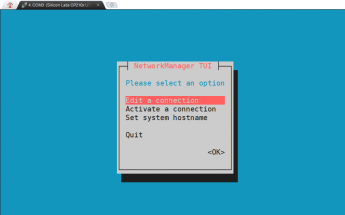
Select Activate a connect and press Enter.
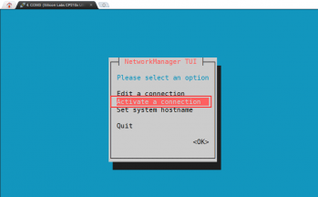
Then you can see all the searched WIFI hotspots.
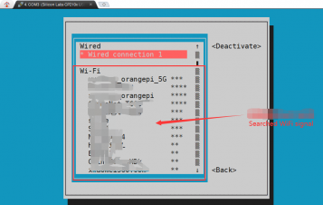
Select the WIFI hotspot you want to connect to, then use the Tab key to move the cursor to Activate and press Enter.
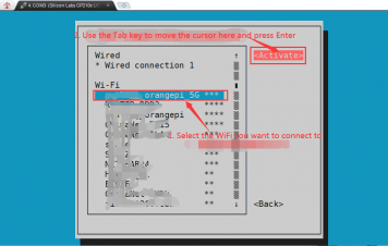
Then a dialog box for entering a password will pop up. Enter the corresponding password in Password and press Enter to start connecting to WIFI.
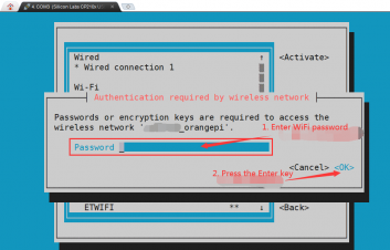
After the WIFI connection is successful, a "*" will be displayed in front of the connected WIFI name
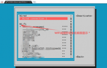
You can view the IP address of the wifi network through the ip addr show wlan0 command.
orangepi@orangepi:~$ ip addr show wlan0
3: wlan0: <BROADCAST,MULTICAST,UP,LOWER_UP> mtu 1500 qdisc pfifo_fast state UP group default qlen 1000
link/ether 24:8c:d3:aa:76:bb brd ff:ff:ff:ff:ff:ff
inet 192.168.1.11/24 brd 192.168.1.255 scope global dynamic noprefixroute wlan0
valid_lft 259069sec preferred_lft 259069sec
inet6 240e:3b7:3240:c4a0:c401:a445:5002:ccdd/64 scope global dynamic noprefixroute
valid_lft 259071sec preferred_lft 172671sec
inet6 fe80::42f1:6019:a80e:4c31/64 scope link noprefixroute
valid_lft forever preferred_lft forever
Use the ping command to test the connectivity of the WiFi network. The ping command can be interrupted by pressing the Ctrl+C shortcut key.
orangepi@orangepi:~$ ping www.orangepi.org -I wlan0
PING www.orangepi.org (182.92.236.130) from 192.168.1.49 wlan0: 56(84) bytes of data.
64 bytes from 182.92.236.130 (182.92.236.130): icmp_seq=1 ttl=52 time=43.5 ms
64 bytes from 182.92.236.130 (182.92.236.130): icmp_seq=2 ttl=52 time=41.3 ms
64 bytes from 182.92.236.130 (182.92.236.130): icmp_seq=3 ttl=52 time=44.9 ms
64 bytes from 182.92.236.130 (182.92.236.130): icmp_seq=4 ttl=52 time=45.6 ms
64 bytes from 182.92.236.130 (182.92.236.130): icmp_seq=5 ttl=52 time=48.8 ms
^C
--- www.orangepi.org ping statistics ---
5 packets transmitted, 5 received, 0% packet loss, time 4006ms
rtt min/avg/max/mdev = 41.321/44.864/48.834/2.484 ms


Testing methods for desktop images
Click the network configuration icon in the upper right corner of the desktop (please do not connect the network cable when testing WIFI).
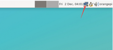
Click More networks in the pop-up drop-down box to see all scanned WIFI hotspots, and then select the WIFI hotspot you want to connect to.

Then enter the password of the WIFI hotspot and click Connect to start connecting to WIFI.
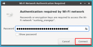
After connecting to WIFI, you can open the browser to check whether you can access the Internet. The browser entrance is shown in the figure below:
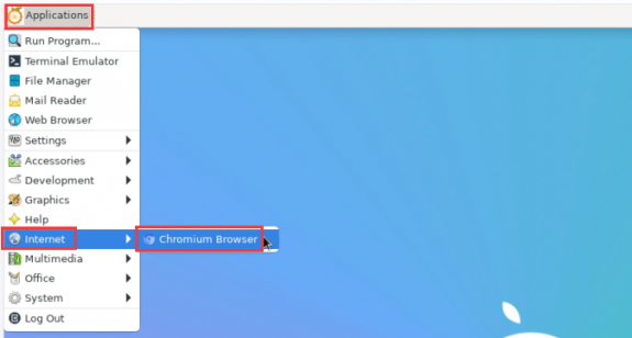
If you can open other web pages after opening the browser, it means the WIFI connection is normal.
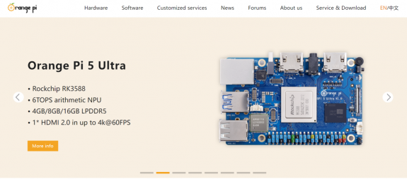


How to set a static IP address
Please do not set a static IP address by modifying the /etc/network/interfaces configuration file.
Using nmtui command to set static IP address
First run the nmtui command.
orangepi@orangepi:~$ sudo nmtui
Then select Edit a connection and press Enter.
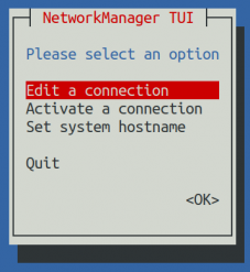
Then select the network interface for which you want to set a static IP address. For example, to set a static IP address for an Ethernet interface, select Wired connection 1.
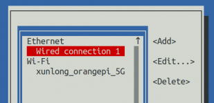
Then select Edit using the Tab key and press Enter.
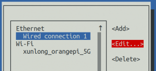
Then use the Tab key to move the cursor to the <Automatic> position shown in the figure below to configure IPv4.


- Press Enter, use the up and down arrow keys to select Manual, and then press Enter to confirm.

The display after selection is as shown below:
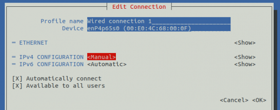
Then use the Tab key to move the cursor to<Show>.
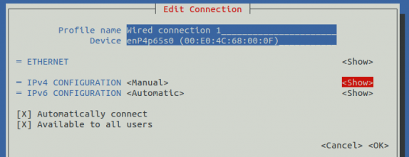
Then press Enter, and the following setting interface will pop up.
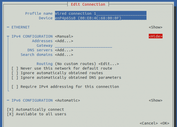
Then you can set the IP address (Addresses), gateway (Gateway) and DNS server address as shown in the figure below (there are many other setting options, please explore them yourself). Please set them according to your specific needs. The value set in the figure below is just an example.
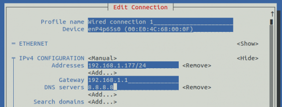
After setting, move the cursor to <OK> in the lower right corner and press Enter to confirm.
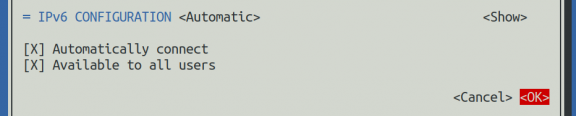
Then click <Back> to return to the previous selection interface.
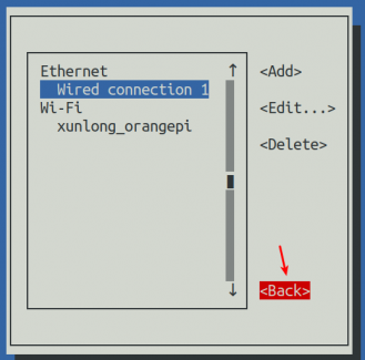
Then select Activate a connection, move the cursor to <OK>, and press Enter.
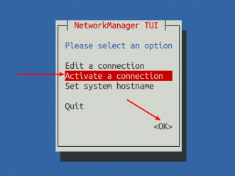
Then select the network interface you want to configure, such as Wired connection 1, move the cursor to <Deactivate>, and press Enter to disable Wired connection 1.
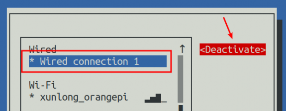
Then please do not move the cursor, and press the Enter key to re-enable Wired connection 1, so that the static IP address set previously will take effect.
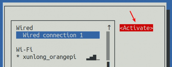
Then you can exit nmtui using the <Back> and Quit buttons.
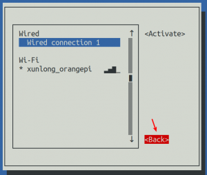
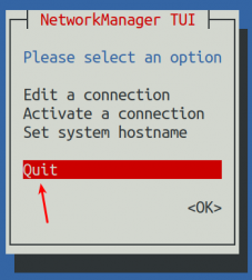
Then use ip addr show enP3p49s0 to see that the IP address of the network port has become the static IP address set previously.
orangepi@orangepi:~$ ip addr show enP3p49s0
2: enP3p49s0: <BROADCAST,MULTICAST,UP,LOWER_UP> mtu 1500 qdisc mq state UP group default qlen 1000
link/ether 00:e0:4c:68:00:0f brd ff:ff:ff:ff:ff:ff
inet 192.168.1.177/24 brd 192.168.1.255 scope global noprefixroute enP3p49s0
valid_lft forever preferred_lft forever
inet6 fe80::d5aa:9a6:cd41:942e/64 scope link noprefixroute
valid_lft forever preferred_lft forever
Then you can test the network connectivity to check whether the IP address is configured OK. The ping command can be interrupted by pressing the Ctrl+Cshortcut key.
orangepi@orangepi:~$ ping 192.168.1.47 -I enP3p49s0
PING 192.168.1.47 (192.168.1.47) from 192.168.1.188 eth0: 56(84) bytes of data.
64 bytes from 192.168.1.47: icmp_seq=1 ttl=64 time=0.233 ms
64 bytes from 192.168.1.47: icmp_seq=2 ttl=64 time=0.263 ms
64 bytes from 192.168.1.47: icmp_seq=3 ttl=64 time=0.273 ms
64 bytes from 192.168.1.47: icmp_seq=4 ttl=64 time=0.269 ms
64 bytes from 192.168.1.47: icmp_seq=5 ttl=64 time=0.275 ms
^C
--- 192.168.1.47 ping statistics ---
5 packets transmitted, 5 received, 0% packet loss, time 4042ms
rtt min/avg/max/mdev = 0.233/0.262/0.275/0.015 ms


How to create a WIFI hotspot through create_ap
create_ap is a script that helps quickly create a WIFI hotspot on Linux. It supports bridge and NAT modes and can automatically combine hostapd, dnsmasq and iptables to complete the setting of WIFI hotspot, avoiding users from making complex configurations. The github address is as follows:
https://github.com/oblique/create_ap
If you are using the latest image, the create_ap script is pre-installed. You can use the create_ap command to create a WIFI hotspot. The basic command format of create_ap is as follows:
create_ap [options] <wifi-interface> [<interface-with-internet>] [<access-point-name> [<passphrase>]]
* options: This parameter can be used to specify encryption method, frequency band of WIFI hotspot, bandwidth mode, network sharing method, etc. You can get the specific options through create_ap -h
* wifi-interface: the name of the wireless network card
* interface-with-internet: the name of the network card that can be connected to the Internet, usually eth0
* access-point-name: hotspot name
* passphrase: hotspot password
create_ap method to create a WIFI hotspot in NAT mode
- Enter the following command to create a WiFi hotspot in NAT mode with the name orangepi and the password orangepi.
orangepi@orangepi:~$ sudo create_ap -m nat wlan0 enP3p49s0 orangepi orangepi
If the following information is output, it means that the WIFI hotspot is created successfully.
orangepi@orangepi:~$ sudo create_ap -m nat wlan0 enP3p49s0 orangepi orangepi
Config dir: /tmp/create_ap.wlan0.conf.Ks6HobEw
PID: 5405
Network Manager found, set ap0 as unmanaged device... DONE
Creating a virtual WiFi interface... ap0 created.
Sharing Internet using method: nat
hostapd command-line interface: hostapd_cli -p /tmp/create_ap.wlan0.conf.Ks6HobEw/hostapd_ctrl
ap0: interface state UNINITIALIZED->ENABLED
ap0: AP-ENABLED
Now take out your mobile phone and find the WIFI hotspot named orangepi created by the development board in the searched WIFI list. Then you can click orangepi to connect to the hotspot. The password is the orangepi set above.
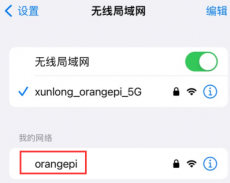
The display after successful connection is as shown below:

In NAT mode, the wireless device connected to the development board's hotspot requests an IP address from the development board's DHCP service, so there will be two different network segments. For example, the IP of the development board here is 192.168.1.X.
orangepi@orangepi:~$ ifconfig enP3p49s0
enP3p49s0: flags=4163<UP,BROADCAST,RUNNING,MULTICAST> mtu 1500
inet 192.168.1.150 netmask 255.255.255.0 broadcast 192.168.1.255
inet6 fe80::938f:8776:5783:afa2 prefixlen 64 scopeid 0x20<link>
ether 4a:a0:c8:25:42:82 txqueuelen 1000 (Ethernet)
RX packets 25370 bytes 2709590 (2.7 MB)
RX errors 0 dropped 50 overruns 0 frame 0
TX packets 3798 bytes 1519493 (1.5 MB)
TX errors 0 dropped 0 overruns 0 carrier 0 collisions 0
device interrupt 83
The DHCP service of the development board will assign an IP address of 192.168.12.0/24 to the device connected to the hotspot by default. At this time, click the connected WIFI hotspot orangepi, and then you can see that the IP address of the mobile phone is 192.168.12.X.
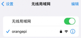
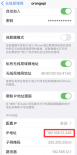
If you want to specify a different network segment for the connected device, you can specify it through the -g parameter, such as using the -g parameter to specify the network segment of the access point AP as 192.168.2.1.
orangepi@orangepi:~$ sudo create_ap -m nat wlan0 enP3p49s0 orangepi orangepi -g 192.168.2.1


At this time, after connecting to the hotspot through the mobile phone, click the connected WIFI hotspot orangepi, and then you can see that the IP address of the mobile phone is 192.168.2.X.


- If you do not specify the --freq-band parameter, the default hotspot created is the 2.4G band. If you want to create a 5G band hotspot, you can specify it with the --freq-band 5 parameter. The specific command is as follows:
orangepi@orangepi:~$ sudo create_ap -m nat wlan0 enP3p49s0 orangepi orangepi --freq-band 5
- If you need to hide the SSID, you can specify the --hidden parameter. The specific command is as follows:
orangepi@orangepi:~$ sudo create_ap -m nat wlan0 enP3p49s0 orangepi orangepi --hidden
At this time, the mobile phone cannot search for the WIFI hotspot. You need to manually specify the WIFI hotspot name and enter the password to connect to the WIFI hotspot.

create_ap method to create a WIFI hotspot in bridge mode
- Enter the following command to create a WiFi hotspot in bridge mode with the name orangepi and the password orangepi.
orangepi@orangepi:~$ sudo create_ap -m bridge wlan0 enP3p49s0 orangepi orangepi
If the following information is output, it means that the WIFI hotspot is created successfully.
orangepi@orangepi:~$ sudo create_ap -m bridge wlan0 enP3p49s0 orangepi orangepi
[sudo] password for orangepi:
Config dir: /tmp/create_ap.wlan0.conf.fg9U5Xgt
PID: 3141
Network Manager found, set ap0 as unmanaged device... DONE
Creating a virtual WiFi interface... ap0 created.
Sharing Internet using method: bridge
Create a bridge interface... br0 created.
hostapd command-line interface: hostapd_cli -p /tmp/create_ap.wlan0.conf.fg9U5Xgt/hostapd_ctrl
ap0: interface state UNINITIALIZED->ENABLED
ap0: AP-ENABLED
Now take out your mobile phone and find the WIFI hotspot named orangepi created by the development board in the searched WIFI list. Then you can click orangepi to connect to the hotspot. The password is the orangepi set above.
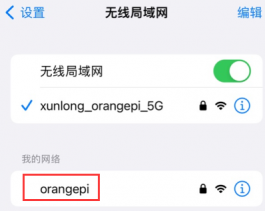
The display after successful connection is as shown below:

In bridge mode, the wireless device connected to the development board's hotspot also requests an IP address from the DHCP service of the main router (the router to which the development board is connected). For example, the IP of the development board here is 192.168.1.X.
orangepi@orangepi:~$ ifconfig enP3p49s0
enP3p49s0: flags=4163<UP,BROADCAST,RUNNING,MULTICAST> mtu 1500
inet 192.168.1.150 netmask 255.255.255.0 broadcast 192.168.1.255
inet6 fe80::938f:8776:5783:afa2 prefixlen 64 scopeid 0x20<link>
ether 4a:a0:c8:25:42:82 txqueuelen 1000 (Ethernet)
RX packets 25370 bytes 2709590 (2.7 MB)
RX errors 0 dropped 50 overruns 0 frame 0
TX packets 3798 bytes 1519493 (1.5 MB)
TX errors 0 dropped 0 overruns 0 carrier 0 collisions 0
device interrupt 83
The IP address of the device connected to the WIFI hotspot is also assigned by the main router, so the mobile phone and development board connected to the WIFI hotspot are in the same network segment. At this time, click the connected WIFI hotspot orangepi, and then you can see that the IP address of the mobile phone is also 192.168.1.X.
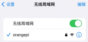
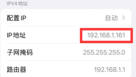
If you do not specify the --freq-band parameter, the default hotspot created is the 2.4G band. If you want to create a 5G band hotspot, you can specify it with the --freq-band 5 parameter. The specific command is as follows:

orangepi@orangepi:~$ sudo create_ap -m bridge wlan0 enP3p49s0 orangepi orangepi --freq-band 5
- If you need to hide the SSID, you can specify the 定--hidden parameter. The specific command is as follows:
orangepi@orangepi:~$ sudo create_ap -m bridge wlan0 enP3p49s0 orangepi orangepi --hidden
At this time, the mobile phone cannot search for the WIFI hotspot. You need to manually specify the WIFI hotspot name and enter the password to connect to the WIFI hotspot.
SSH remote login development board
By default, Linux systems have SSH remote login enabled, and allow the root user to log in to the system. Before SSH login, you must first ensure that the Ethernet or WiFi network is connected, and then use the ip addr command or check the router to obtain the IP address of the development board.
SSH remote login to the development board under Ubuntu
- Get the IP address of the development board.
- Then you can log in to the Linux system remotely through the ssh command.
test@test:~$ ssh root@192.168.x.xxx #Need to be replaced with the IP address of the development board
root@192.168.x.xx's password: #Enter the password here. The default password is orangepi
Note that when you enter the password, the screen will not display the specific content of the password you entered. Please do not think that there is any malfunction. Just press Enter after entering it.
If the prompt refuses to connect, as long as you are using the image provided by Orange Pi, please do not doubt whether the password orangepi is wrong, but look for other reasons.
After successfully logging into the system, the display is as shown below:
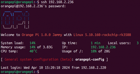
If ssh cannot log in to the Linux system normally, first check whether the IP address of the development board can be pinged. If the ping is successful, you can log in to the Linux system through the serial port or HDMI display and then enter the following command on the development board to try to connect:

root@orangepi:~# reset_ssh.sh
If it still doesn't work, please re-burn the system and try again.
SSH remote login development board under Windows
First, obtain the IP address of the development board.
Under Windows, you can use MobaXterm to remotely log in to the development board. First, create a new ssh session.
Open Session.
Select SSH in Session Setting.
Enter the IP address of the development board in Remote host.
Enter the Linux user name root or orangepi in Specify username.
Click OK.
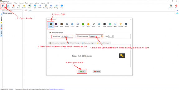
You will then be prompted to enter a password. The default password for both root and orangepi users is orangepi.
Please note that when you enter the password, the specific content of the password will not be displayed on the screen. Please do not think that there is any malfunction. Just press Enter after entering it.


- After successfully logging into the system, the display is as shown below:

How to use ADB
How to use network adb
After the system starts, please make sure that adbd has been started.
orangepi@orangepi:~$ ps -ax | grep "adbd"
808 ? Sl 0:00 /usr/bin/adbd
3707 ttyFIQ0 S+ 0:00 grep --color=auto adbd
Then check the IP address of the development board and write it down.
Then install adb tool on your Ubuntu PC.
test@test:~$ sudo apt-get update
test@test:~$ sudo apt-get install -y adb
Then use the following command to connect to the network adb.
test@test:~$ adb connect 192.168.1.xx:5555 #Please replace IP address with the IP address of the development board
- daemon not running; starting now at tcp:5037
- daemon started successfully
connected to 192.168.1.xx:5555
test@test:~$ adb devices
List of devices attached
192.168.1.xx:5555 device
- Then use the following command to log in to the Linux system of the development board.
test@test:~$ adb shell
root@orangepi5ultra:/# <--- Seeing this prompt means you have successfully logged into the development board
The command to upload files to the development board using adb is as follows:
test@test:~$ adb push filename /root
filename: 1 file pushed. 3.7 MB/s (1075091 bytes in 0.277s)
The command to restart the development board using adb is as follows:
test@test:~$ adb reboot
If you don't have the adb tool in your Windows system, you can use the adb program in the RKDevTool software (this software is useful in the section on how to burn the Android image to SPIFlash+NVMe SSD).

An example using adb in Windows is shown below:

Use a USB male-to-male data cable to connect to adb
First, prepare a good quality USB male-to-male data cable.
Then connect the development board to the Ubuntu PC via a USB male-to-male data cable. The location of the USB interface that supports the device function of the development board is shown in the figure below:
Then run the following command to set the USB interface to device mode.
orangepi@orangepi:~$ sudo set_device.sh
If the set_device.sh script does not exist in the Linux system, use the following command directly:
orangepi@orangepi:~$ sudo bash -c "echo device > /sys/kernel/debug/usb/fc000000.usb/mode"
orangepi@orangepi:~$ sudo systemctl restart usbdevice
Then please make sure adbd is started.
orangepi@orangepi:~$ ps -ax | grep "adbd"
808 ? Sl 0:00 /usr/bin/adbd
3707 ttyFIQ0 S+ 0:00 grep --color=auto adbd
Then install the adb tool on your Ubuntu PC.
test@test:~$ sudo apt-get update
test@test:~$ sudo apt-get install -y adb
Then use the following command to check whether the adb device is recognized.
test@test:~$ adb devices
List of devices attached
e0f9f71bc343c305 device
- Then use the following command to log in to the Linux system of the development board.
test@test:~$ adb shell
root@orangepi5ultra:/# <---Seeing this prompt means you have successfully logged into the development board
The command to upload files to the development board using adb is as follows:
test@test:~$ adb push filename /root
filename: 1 file pushed. 3.7 MB/s (1075091 bytes in 0.277s)
If you don't have the adb tool in your Windows system, you can use the adb program in the RKDevTool software (this software is useful in the section on how to burn the Android image to SPIFlash+NVMe SSD).
An example using adb in Windows is shown below:

How to upload files to the Linux system of the development board
How to upload files from Ubuntu PC to the Linux system of the development board
How to upload files using the scp command
Use the scp command to upload files from the Ubuntu PC to the Linux system of the development board. The specific commands are as follows:
file_path: needs to be replaced with the path of the file to be uploaded.
orangepi is the user name of the development board's Linux system, which can also be replaced with other names, such as root.
192.168.xx.xx: is the IP address of the development board, please modify it according to the actual situation.
/home/orangepi: is the path in the development board's Linux system, which can also be changed to other paths.
test@test:~$ scp file_path orangepi@192.168.xx.xx:/home/orangepi/
If you want to upload a folder, you need to add the -r parameter.
test@test:~$ scp -r dir_path orangepi@192.168.xx.xx:/home/orangepi/
There are more uses for scp. Please use the following command to view the man manual.
test@test:~$ man scp
How to upload files using FileZilla
First install filezilla in your Ubuntu PC.
test@test:~$ sudo apt install -y filezilla
Then open filezilla using the command below.
test@test:~$ filezilla
The interface after opening filezilla is as shown below. At this time, the remote site on the right is empty.
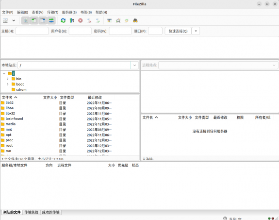
The method of connecting the development board is shown in the figure below:


Then select Save Password and click OK.
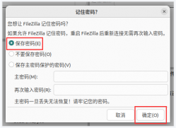
Then select Always trust this host and click OK.


- After the connection is successful, you can see the directory structure of the development board's Linux file system on the right side of the filezilla software.

- Then select the path to be uploaded to the development board on the right side of the filezilla software, then select the file to be uploaded in the Ubuntu PC on the left side of the filezilla software, right-click the mouse, and then click the upload option to start uploading the file to the development board.

After uploading is complete, you can go to the corresponding path in the Linux system of the development board to view the uploaded files.
The method for uploading a folder is the same as that for uploading a file, so I will not go into details here.
How to upload files from Windows PC to the Linux system of the development board
How to upload files using FileZilla
- First download the installation file of the Windows version of the filezilla software. The download link is as follows:
https://filezilla-project.org/download.php?type=client

The downloaded installation package is as shown below, then double-click to install directly.
FileZilla_Server_1.5.1_win64-setup.exe
During the installation process, select Decline on the following installation interface, and then select Next>.

- The interface after opening filezilla is as shown below. At this time, the remote site on the right is empty.

- The method of connecting the development board is shown in the figure below:

- Then select Save Password and click OK.

- Then select Always trust this host and click OK.

- After the connection is successful, you can see the directory structure of the development board's Linux file system on the right side of the filezilla software.

- Then select the path to be uploaded to the development board on the right side of the filezilla software, then select the file to be uploaded in the Windows PC on the left side of the filezilla software, right-click the mouse, and then click the upload option to start uploading the file to the development board.

After uploading is complete, you can go to the corresponding path in the Linux system of the development board to view the uploaded files.
The method for uploading a folder is the same as that for uploading a file, so I will not go into details here.
HDMI test
HDMI display test
Use an HDMI to HDMI cable to connect the Orange Pi development board and the HDMI display.
After starting the Linux system, if the HDMI monitor has image output, it means that the HDMI interface is working properly.
Note that although many laptops have HDMI interfaces, the HDMI interfaces of laptops generally only have output functions and do not have HDMI in functions, which means that the HDMI output of other devices cannot be displayed on the laptop screen.
When you want to connect the HDMI of the development board to the HDMI interface of the laptop, please first confirm that your laptop supports the HDMI in function.
When there is no display on HDMI, please first check whether the HDMI cable is plugged in tightly. After confirming that the connection is OK, you can try a different screen to see if there is any display.
HDMI resolution setting method
First, open Display in Settings.

Then you can see the current resolution of the system.
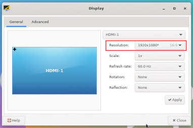
Click the drop-down box of Resolution to see all the resolutions currently supported by the monitor.
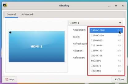
Then select the resolution you want to set and click Apply.
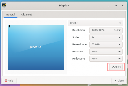
After the new resolution is set, select Keep the configuration.
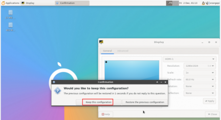


Test method for HDMI RX
The location of the HDMI RX interface on the development board is as follows:
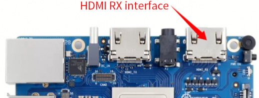
First, use the HDMI to HDMI cable shown in the figure below to connect the HDMI output of other devices to the HDMI RX interface of the development board.

Then open a terminal on the desktop and run the test_hdmiin.sh script
[orangepi@orangepi ~]$ sudo test_hdmiin.sh
Then you can see the input screen of HDMI RX (the HDMI RX in the figure below shows the HDMI output screen of the opi5 development board, and a video is playing at this time). By default, the test_hdmiin.sh script will play the audio input from HDMI RX to the HDMI_TX of the development board and the headphones.
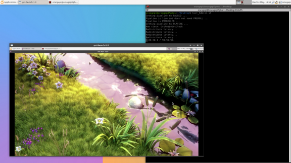


How to use Bluetooth
Testing methods for desktop images
Click the Bluetooth icon in the upper right corner of the desktop.
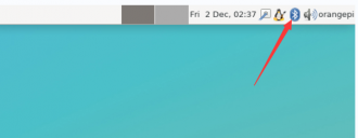
Then select the adapter.
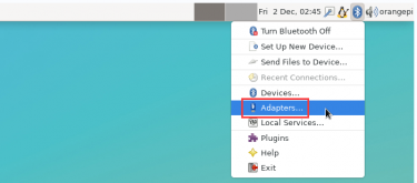
If the following interface is displayed, select Yes.

Then set the Visibility Setting to Always visible in the Bluetooth adapter settings interface, and then turn it off.
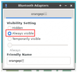
Then open the configuration interface of the Bluetooth device.
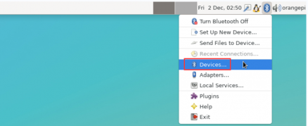
Click Search to start scanning for surrounding Bluetooth devices.
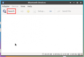


Then select the Bluetooth device you want to connect to, and right-click the mouse to pop up the operation interface for this Bluetooth device. Select Pair to start pairing. The demonstration here is pairing with an Android phone.
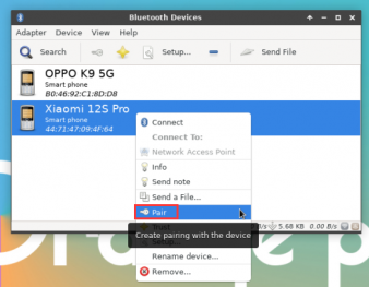
During pairing, a pairing confirmation box will pop up in the upper right corner of the desktop. Select Confirm. Confirmation is also required on the phone.
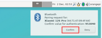
After pairing with the phone, you can select the paired Bluetooth device, then right-click and select Send a File to start sending a picture to the phone.
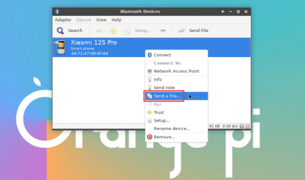
The interface for sending pictures is as follows:
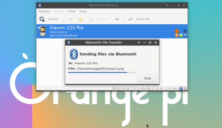


USB interface test
The USB port can be connected to a USB hub to expand the number of USB ports.
Test by connecting USB mouse or keyboard
- Insert the USB keyboard into the USB port of the Orange Pi development board.
- Connect the Orange Pi development board to the HDMI display
- If the mouse or keyboard can operate the system normally, it means that the USB interface is working properly (the mouse can only be used in the desktop version of the system)
Test by connecting USB storage device
- First, insert the USB flash drive or USB mobile hard disk into the USB port of the Orange Pi development board.
- Execute the following command. If you can see the output of sdX, it means that the USB disk has been successfully recognized.
orangepi@orangepi:~$ cat /proc/partitions | grep "sd*"
major minor #blocks name
8 0 30044160 sda
8 1 30043119 sda1
- Use the mount command to mount the USB drive to /mnt, and then you can view the files in the USB drive.
orangepi@orangepi:~$ sudo mount /dev/sda1 /mnt/
orangepi@orangepi:~$ ls /mnt/
test.txt
- After mounting, you can use the df -h command to view the capacity usage and mount point of the USB drive.
orangepi@orangepi:~$ df -h | grep "sd"
/dev/sda1 29G 208K 29G 1% /mnt
USB wireless network card test
The currently tested USB wireless network cards are as follows. Please test other models of USB wireless network cards by yourself. If they cannot be used, you need to transplant the corresponding USB wireless network card driver
| Serial number | Model | |
| 1 | RTL8723BU
Support 2.4G WIFI+BT4.0 |
File:Orange Pi 5 Ultra-image2 52.png |
| 2 | RTL8811
Support 2.4G +5G WIFI |
File:Orange Pi 5 Ultra-image2 53.png |
| 3 | RTL8821CU
Support 2.4G +5G WIFI Support BT 4.2 |
RTL8723BU test
First, insert the RTL8723BU wireless network card module into the USB port of the development board.
Then the Linux system will automatically load the RTL8723BU Bluetooth and WIFI related kernel modules. Through the lsmod command, you can see that the following kernel modules have been automatically loaded
orangepi@orangepi:~$ lsmod
Module Size Used by
rfcomm 57344 16
rtl8xxxu 106496 0
rtk_btusb 61440 0
You can see the loading information of the RTL8723BU module through the dmesg command
orangepi@orangepi:~$ dmesg
......
[ 83.438901] usb 2-1: new high-speed USB device number 2 using ehci-platform
[ 83.588375] usb 2-1: New USB device found, idVendor=0bda, idProduct=b720, bcdDevice= 2.00
[ 83.588403] usb 2-1: New USB device strings: Mfr=1, Product=2, SerialNumber=3
[ 83.588422] usb 2-1: Product: 802.11n WLAN Adapter
[ 83.588443] usb 2-1: Manufacturer: Realtek
[ 83.588460] usb 2-1: SerialNumber: 00e04c000001
[ 83.601974] Bluetooth: hci0: RTL: examining hci_ver=06 hci_rev=000b lmp_ver=06 lmp_subver=8723
[ 83.603894] Bluetooth: hci0: RTL: rom_version status=0 version=1
[ 83.603920] Bluetooth: hci0: RTL: loading rtl_bt/rtl8723b_fw.bin
[ 83.610108] Bluetooth: hci0: RTL: loading rtl_bt/rtl8723b_config.bin
[ 83.611274] Bluetooth: hci0: RTL: cfg_sz 68, total sz 22564
[ 83.658494] rtk_btusb: Realtek Bluetooth USB driver ver 3.1.6d45ddf.20220519-142432
[ 83.658651] usbcore: registered new interface driver rtk_btusb
[ 83.667124] usb 2-1: This Realtek USB WiFi dongle (0x0bda:0xb720) is untested!
[ 83.667137] usb 2-1: Please report results to Jes.Sorensen@gmail.com
[ 83.890140] usb 2-1: Vendor: Realtek
[ 83.890153] usb 2-1: Product: 802.11n WLAN Adapter
[ 83.890159] usb 2-1: rtl8723bu_parse_efuse: dumping efuse (0x200 bytes):
......
[ 83.890412] usb 2-1: RTL8723BU rev E (SMIC) 1T1R, TX queues 3, WiFi=1, BT=1, GPS=0, HI PA=0
[ 83.890417] usb 2-1: RTL8723BU MAC: 00:13:ef:f4:58:ae
[ 83.890421] usb 2-1: rtl8xxxu: Loading firmware rtlwifi/rtl8723bu_nic.bin
[ 83.895289] usb 2-1: Firmware revision 35.0 (signature 0x5301)
[ 84.050893] Bluetooth: hci0: RTL: fw version 0x0e2f9f73
[ 84.266905] Bluetooth: RFCOMM TTY layer initialized
[ 84.266949] Bluetooth: RFCOMM socket layer initialized
[ 84.266999] Bluetooth: RFCOMM ver 1.11
[ 84.884270] usbcore: registered new interface driver rtl8xxxu
[ 84.912046] rtl8xxxu 2-1:1.2 wlx0013eff458ae: renamed from wlan0
Then use the sudo ifconfig command to see the device node of RTL8723BU WIFI. For the connection and test methods of WIFI, please refer to the WIFI connection test section.
orangepi@orangepi:~$ sudo ifconfig wlx0013eff458ae
wlx0013eff458ae: flags=4099<UP,BROADCAST,MULTICAST> mtu 1500
ether 00:13:ef:f4:58:ae txqueuelen 1000 (Ethernet)
RX packets 0 bytes 0 (0.0 B)
RX errors 0 dropped 0 overruns 0 frame 0
TX packets 0 bytes 0 (0.0 B)
TX errors 0 dropped 0 overruns 0 carrier 0 collisions 0
Then you can see the USB Bluetooth device through the hciconfig command
orangepi@orangepi:~$ sudo apt update && sudo apt -y install bluez
orangepi@orangepi:~$ hciconfig
hci0: Type: Primary Bus: USB
BD Address: 00:13:EF:F4:58:AE ACL MTU: 820:8 SCO MTU: 255:16
DOWN
RX bytes:1252 acl:0 sco:0 events:125 errors:0
TX bytes:23307 acl:0 sco:0 commands:125 errors:0
You can also see the Bluetooth icon on the desktop. At this time, Bluetooth is not turned on, so a red x is displayed.

Click Turn Bluetooth On to turn on Bluetooth
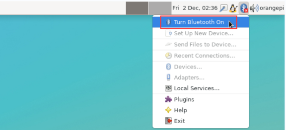
The display after turning on Bluetooth is as follows

For the Bluetooth testing method, please refer to the Bluetooth Usage section, which will not be repeated here.


RTL8811 Test
First, insert the RTL8811 wireless network card module into the USB port of the development board.
Then the Linux system will automatically load the kernel modules related to RTL8811 WIFI. You can see the following kernel modules have been automatically loaded through the lsmod command:
orangepi@orangepi:~$ lsmod
Module Size Used by
8821cu 1839104 0
You can see the loading information of the RTL8811 module through the dmesg command
orangepi@orangepi:~$ dmesg
[ 118.618194] usb 2-1: new high-speed USB device number 2 using ehci-platform
[ 118.767152] usb 2-1: New USB device found, idVendor=0bda, idProduct=c811, bcdDevice= 2.00
[ 118.767181] usb 2-1: New USB device strings: Mfr=1, Product=2, SerialNumber=3
[ 118.767199] usb 2-1: Product: 802.11ac NIC
[ 118.767219] usb 2-1: Manufacturer: Realtek
[ 118.767235] usb 2-1: SerialNumber: 123456
[ 119.500530] usbcore: registered new interface driver rtl8821cu
[ 119.525498] rtl8821cu 2-1:1.0 wlx1cbfced9d260: renamed from wlan0
Then use the sudo ifconfig command to see the WIFI device node. For WIFI connection and test methods, please refer to the WIFI connection test section. I will not repeat it here.
orangepi@orangepi:~$ sudo ifconfig wlx1cbfced9d260
wlx1cbfced9d260: flags=4099<UP,BROADCAST,MULTICAST> mtu 1500
ether 1c:bf:ce:d9:d2:60 txqueuelen 1000 (Ethernet)
RX packets 0 bytes 0 (0.0 B)
RX errors 0 dropped 0 overruns 0 frame 0
TX packets 0 bytes 0 (0.0 B)
TX errors 0 dropped 0 overruns 0 carrier 0 collisions 0
RTL8821CU test
First insert the rtl8821cu wireless network card module into the USB interface of the development board
Then use the lsusb command to see the device information of the lsusbcu usb wifi module. Please make sure that the USB module is not in Driver CDROM Mode.
orangepi@orangepi:~$ lsusb | grep "Realtek"
Bus 002 Device 003: ID 0bda:c820 Realtek Semiconductor Corp. 802.11ac NIC
orangepi@orangepi:~$ lsusb | grep "Realtek"
Bus 002 Device 002: ID 0bda:1a2b Realtek Semiconductor Corp. RTL8188GU 802.11n WLAN Adapter (Driver CDROM Mode)
If the USB WIFI module is in Driver CDROM Mode as seen by the lsusb command, please unplug and re-plug the USB WIFI module. If it still doesn't work, please manually execute the following command to switch the mode:
orangepi@orangepi:~$ sudo usb_modeswitch -KW -v 0bda -p 1a2b
The Linux system will automatically load the rtl8821cu Bluetooth and WiFi related kernel modules. You can see the following kernel modules have been automatically loaded through the lsmod command:
orangepi@orangepi:~$ lsmod
Module Size Used by
8821cu 1839104 0
rtk_btusb 61440 0
You can see the loading information of the rtl8821cu module through the dmesg command
orangepi@orangepi:~$ dmesg
......
[ 57.083693] usb 2-1: new high-speed USB device number 2 using ehci-platform
[ 57.231888] usb 2-1: New USB device found, idVendor=0bda, idProduct=1a2b, bcdDevice= 2.00
[ 57.231916] usb 2-1: New USB device strings: Mfr=1, Product=2, SerialNumber=0
[ 57.231937] usb 2-1: Product: DISK
[ 57.231956] usb 2-1: Manufacturer: Realtek
[ 57.242594] usb-storage 2-1:1.0: USB Mass Storage device detected
[ 57.245674] scsi host0: usb-storage 2-1:1.0
[ 58.069172] usb 2-1: USB disconnect, device number 2
[ 58.440025] usb 2-1: new high-speed USB device number 3 using ehci-platform
[ 58.587819] usb 2-1: New USB device found, idVendor=0bda, idProduct=c820, bcdDevice= 2.00
[ 58.587827] usb 2-1: New USB device strings: Mfr=1, Product=2, SerialNumber=3
[ 58.587833] usb 2-1: Product: 802.11ac NIC
[ 58.587838] usb 2-1: Manufacturer: Realtek
[ 58.587844] usb 2-1: SerialNumber: 123456
[ 58.610463] rtk_btusb: Realtek Bluetooth USB driver ver 3.1.6d45ddf.20220519-142432
[ 58.610656] usbcore: registered new interface driver rtk_btusb
[ 58.634631] Bluetooth: hci0: RTL: examining hci_ver=08 hci_rev=000c lmp_ver=08 lmp_subver=8821
[ 58.636729] Bluetooth: hci0: RTL: rom_version status=0 version=1
[ 58.636740] Bluetooth: hci0: RTL: loading rtl_bt/rtl8821c_fw.bin
[ 58.664190] Bluetooth: hci0: RTL: loading rtl_bt/rtl8821c_config.bin
[ 58.664746] Bluetooth: hci0: RTL: cfg_sz 10, total sz 31990
[ 59.122471] Bluetooth: hci0: RTL: fw version 0x829a7644
[ 59.265513] usbcore: registered new interface driver rtl8821cu
[ 59.280119] rtl8821cu 2-1:1.2 wlx90de80521825: renamed from wlan0
Then use the sudo ifconfig command to see the device node of rtl8821cu wifi. For the connection and test methods of wifi, please refer to the WIFI connection test section. I will not repeat it here.
orangepi@orangepi:~$ sudo ifconfig wlx90de80521825
wlx90de80521825: flags=4099<UP,BROADCAST,MULTICAST> mtu 1500
ether 00:13:ef:f4:58:ae txqueuelen 1000 (Ethernet)
RX packets 0 bytes 0 (0.0 B)
RX errors 0 dropped 0 overruns 0 frame 0
TX packets 0 bytes 0 (0.0 B)
TX errors 0 dropped 0 overruns 0 carrier 0 collisions 0
Then you can see the USB Bluetooth device through the hciconfig command
orangepi@orangepi:~$ sudo apt-get update && sudo apt-get install -y bluez
orangepi@orangepi:~$ hciconfig
hci0: Type: Primary Bus: USB
BD Address: 00:13:EF:F4:58:AE ACL MTU: 820:8 SCO MTU: 255:16
DOWN
RX bytes:1252 acl:0 sco:0 events:125 errors:0
TX bytes:23307 acl:0 sco:0 commands:125 errors:0
You can also see the Bluetooth icon on the desktop. At this time, Bluetooth is not turned on, so a red x is displayed.
Click Turn Bluetooth On to turn on Bluetooth
The display after turning on Bluetooth is as follows
For the Bluetooth testing method, please refer to the Bluetooth Usage section, which will not be repeated here.
USB camera test
First, you need to prepare a USB camera that supports UVC protocol as shown in the figure below or similar, and then insert the USB camera into the USB port of the Orange Pi development board.

Through the v4l2-ctl command, you can see that the device node information of the USB camera is /dev/video0
orangepi@orangepi:~$ v4l2-ctl --list-devices
Q8 HD Webcam: Q8 HD Webcam (usb-fc880000.usb-1):
/dev/video0
/dev/video1
/dev/media0
Note that the l in v4l2 is a lowercase letter l, not the number 1.
In addition, the video number is not always video0, please refer to the actual one you see.
In the desktop system, you can use Cheese to directly open the USB camera. The Cheese opening method is shown in the figure below:
If cheese is not pre-installed, you can install it using the following command:
orangepi@orangepi:~$ sudo apt-get install -y cheese
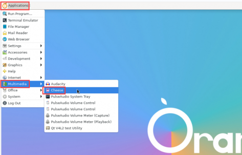
The interface after Cheese opens the USB camera is as shown below:
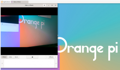
How to use fswebcam to test USB camera
Install fswebcam
orangepi@orangepi:~$ sudo apt update
orangepi@orangepi:~$ sudo apt-get install -y fswebcam
After installing fswebcam, you can use the following command to take photos
-d option is used to specify the device node of the USB camera
--no-banner is used to remove the watermark of the photo
-r option is used to specify the resolution of the photo
-S option is used to set the number of frames to skip in the past
./image.jpg is used to set the name and path of the generated photo
orangepi@orangepi:~$ sudo fswebcam -d /dev/video0 \
--no-banner -r 1280x720 -S 5 ./image.jpg
In the server version of Linux, after taking the photo, you can use the scp command to transfer the photo to the Ubuntu PC for mirror viewing.
orangepi@orangepi:~$ scp image.jpg test@192.168.1.55:/home/test (Modify the IP address and path according to actual situation)
In the desktop version of Linux system, you can directly view the captured pictures through the HDMI display


Audio Test
Testing Audio Methods on Desktop Systems
First open the file manager.
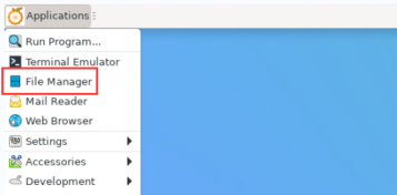
Then find the following file (if there is no such audio file in the system, you can upload an audio file to the system yourself).
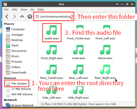
Then select the audio.wav file, right-click and choose to open it with vlc or mpv to start playing.
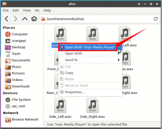
Methods for switching between different audio devices such as HDMI playback and headphone playback.
First open the volume control interface.
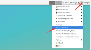
When playing audio, the audio device options that the playback software can use will be displayed in Playback, as shown in the figure below. Here you can set which audio device you want to play to.
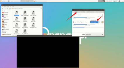
If you don't see the HDMI audio device option, try unplugging the HDMI cable.


How to play audio using commands
Headphone jack audio playback test
First, plug the earphone into the earphone jack of the development board.
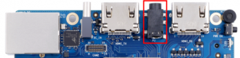
Then you can use the aplay -l command to view the sound card devices supported by the Linux system. From the output below, we can see that card 2 is the es8388 sound card device, which is the sound card device of the headset.
orangepi@orangepi:~$ aplay -l
**** List of PLAYBACK Hardware Devices ****
card 0: rockchiphdmi1 [rockchip-hdmi1], device 0: rockchip-hdmi1 i2s-hifi-0 [rockchip-hdmi1 i2s-hifi-0]
Subdevices: 1/1
Subdevice #0: subdevice #0
card 2: rockchipes8388 [rockchip,es8388], device 0: dailink-multicodecs ES8323.7-0011-0 [dailink-multicodecs ES8323.7-0011-0]
Subdevices: 1/1
Subdevice #0: subdevice #0
Then use the aplay command to play the audio file that comes with the system. If the headphones can hear the sound, it means that the hardware can be used normally.
orangepi@orangepi:~$ aplay -D hw:2,0 /usr/share/sounds/alsa/audio.wav
Playing WAVE 'audio.wav' : Signed 16 bit Little Endian, Rate 44100 Hz, Stereo

HDMI audio playback test
First, use an HDMI to HDMI cable to connect the Orange Pi development board to the TV (other HDMI displays need to ensure that they can play audio)
Then check the HDMI sound card serial number. From the output below, we can know that the HDMI TX sound card is card 0
orangepi@orangepi:~$ aplay -l
**** List of PLAYBACK Hardware Devices ****
card 0: rockchiphdmi1 [rockchip-hdmi1], device 0: rockchip-hdmi1 i2s-hifi-0 [rockchip-hdmi1 i2s-hifi-0]
Subdevices: 1/1
Subdevice #0: subdevice #0
......
Then use the aplay command to play the audio file that comes with the system. If the HDMI display or TV can hear the sound, it means that the hardware can be used normally.
orangepi@orangepi:~$ aplay -D hw:0,0 /usr/share/sounds/alsa/audio.wav
How to test recording using commands
There is an onboard MIC on the development board, the location is as follows:
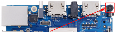
Run the test_record.sh main command to record an audio clip through the onboard MIC and then play it to the HDMI and headphones.
orangepi@orangepi:~$ test_record.sh main
Start recording: /tmp/test.wav
Recording WAVE '/tmp/test.wav' : Signed 16 bit Little Endian, Rate 44100 Hz, Stereo
Start playing
Playing WAVE '/tmp/test.wav' : Signed 16 bit Little Endian, Rate 44100 Hz, Stereo
Playing WAVE '/tmp/test.wav' : Signed 16 bit Little Endian, Rate 44100 Hz, Stereo
In addition to the onboard MIC, we can also record audio through headphones with MIC function. After inserting the headphones with MIC function into the development board, running the test_record.sh headset command will record an audio through the headphones and then play it to HDMI and headphones.
orangepi@orangepi:~$ test_record.sh headset
Start recording: /tmp/test.wav
Recording WAVE '/tmp/test.wav' : Signed 16 bit Little Endian, Rate 44100 Hz, Stereo
Start playing
Playing WAVE '/tmp/test.wav' : Signed 16 bit Little Endian, Rate 44100 Hz, Stereo
Playing WAVE '/tmp/test.wav' : Signed 16 bit Little Endian, Rate 44100 Hz, Stereo

Temperature sensor
- The command to view the system temperature sensor is:
orangepi@orangepi:~$ sensors
gpu_thermal-virtual-0
Adapter: Virtual device
temp1: +47.2°C
littlecore_thermal-virtual-0
Adapter: Virtual device
temp1: +47.2°C
bigcore0_thermal-virtual-0
Adapter: Virtual device
temp1: +47.2°C
tcpm_source_psy_6_0022-i2c-6-22
Adapter: rk3x-i2c
in0: 0.00 V (min = +0.00 V, max = +0.00 V)
curr1: 0.00 A (max = +0.00 A)
npu_thermal-virtual-0
Adapter: Virtual device
temp1: +47.2°C
center_thermal-virtual-0
Adapter: Virtual device
temp1: +47.2°C
bigcore1_thermal-virtual-0
Adapter: Virtual device
temp1: +47.2°C
soc_thermal-virtual-0
Adapter: Virtual device
temp1: +47.2°C (crit = +115.0°C)
The command to check the current temperature of the nvme ssd solid state drive is:
orangepi@orangepi:~$ sudo smartctl -a /dev/nvme0 | grep "Temperature:"
Temperature: 40 Celsius
40 Pin Interface Pin Description
Please refer to the following figure for the order of the 40 pin interface pins of the Orange Pi 5 Ultra development board
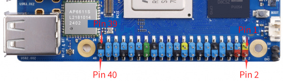
The functions of the 40 pin interface pins of the Orange Pi 5 Ultra development board are shown in the following table
Below is the complete pin diagram of 40pin
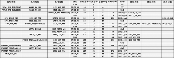
The table below is a picture of the left half of the complete table above, which can be seen more clearly
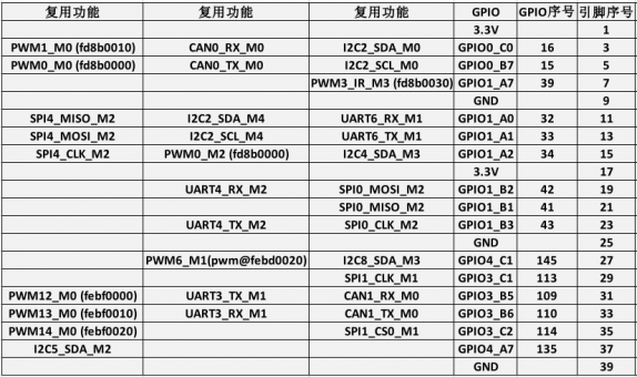
The table below is the right half of the complete table above, which can be seen more clearly
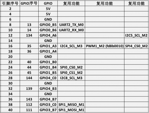
In the table above, the base addresses of the corresponding registers are marked for pwm, which is useful for checking which pwmchip in /sys/class/pwm/ corresponds to which pwm pin in the 40-pin header.
There are a total of 28 GPIO ports in the 40pin interface, and the voltage of all GPIO ports is 3.3v


How to install wiringOP
Note that wiringOP is pre-installed in the Linux image released by Orange Pi. Unless the wiringOP code is updated, you do not need to download, compile and install it again. You can use it directly.
The storage path of the compiled wiringOP deb package in orangepi-build is:
orangepi-build/external/cache/debs/arm64/wiringpi_x.xx.deb
After entering the system, you can run the gpio readall command. If you can see the following output, it means wiringOP has been pre-installed and can be used normally.

Download the wiringOP code
orangepi@orangepi:~$ sudo apt update
orangepi@orangepi:~$ sudo apt install -y git
orangepi@orangepi:~$ git clone https://github.com/orangepi-xunlong/wiringOP.git -b next
Note that Orange Pi 5 Ultra needs to download the wiringOP next branch code, please do not miss the -b next parameter.
If you have problems downloading the code from GitHub, you can directly use the wiringOP source code that comes with the Linux image, which is stored in /usr/src/wiringOP.
Compile and install wiringOP
orangepi@orangepi:~$ cd wiringOP
orangepi@orangepi:~/wiringOP$ sudo ./build clean
orangepi@orangepi:~/wiringOP$ sudo ./build
Test the output of the gpio readall command as follows
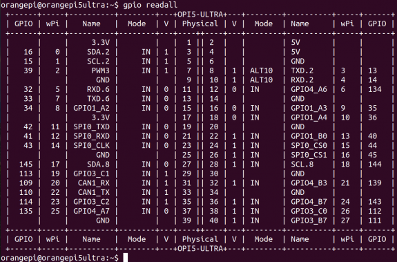
40pin interface GPIO, I2C, UART, SPI, CAN and PWM test
40pin GPIO port test
The Linux system released by Orange Pi has a pre-installed blink_all_gpio program, which will set all 28 GPIO ports in the 40-pin to switch high and low levels continuously.
After running the blink_all_gpio program, when you use a multimeter to measure the voltage level of the GPIO port, you will find that the GPIO pin will switch between 0 and 3.3v. Using this program, we can test whether the GPIO port can work properly.
The way to run the blink_all_gpio program is as follows:
orangepi@orangepi:~$ sudo blink_all_gpio #Remember to add sudo permissions
[sudo] password for orangepi: #You need to enter a password here
There are a total of 28 GPIO ports available in the 40 pins of the development board. The following uses pin 7, which corresponds to GPIO GPIO1_A7 and wPi serial number 2, as an example to demonstrate how to set the high and low levels of the GPIO port.
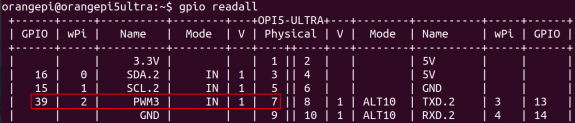
First set the GPIO port to output mode, where the third parameter needs to input the wPi number corresponding to the pin
root@orangepi:~/wiringOP# gpio mode 2 out
Then set the GPIO port to output a low level. After setting, you can use a multimeter to measure the voltage value of the pin. If it is 0v, it means that the low level is set successfully.
root@orangepi:~/wiringOP# gpio write 2 0
Using gpio readall, you can see that the value of pin 7 (V) has changed to 0
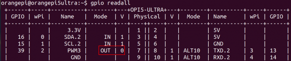
Then set the GPIO port to output a high level. After setting, you can use a multimeter to measure the voltage value of the pin. If it is 3.3v, it means that the high level is set successfully.
root@orangepi:~/wiringOP# gpio write 2 1
Using gpio readall, you can see that the value of pin 7 (V) has changed to 1
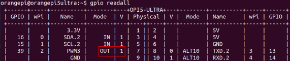
The setting method of other pins is similar. Just change the serial number of wPi to the serial number corresponding to the pin.


40 How to set pull-up and pull-down resistors on GPIO pin
Note that the following 10 GPIO pins of Orange Pi 5 Ultra have external 3.3V pull-up, so setting the pull-down is invalid.

Below, we take pin 11, which corresponds to GPIO GPIO1_A0 and wPi number 5, as an example to demonstrate how to set the pull-up and pull-down resistors of the GPIO port.
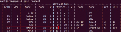
First, you need to set the GPIO port to input mode. The third parameter needs to enter the wPi number corresponding to the pin.
root@orangepi:~# gpio mode 5 in
After setting to input mode, execute the following command to set the GPIO port to pull-up mode
root@orangepi:~# gpio mode 5 up
Then enter the following command to read the level of the GPIO port. If the level is 1, it means that the pull-up mode is set successfully.
root@orangepi:~# gpio read 5
1
Then execute the following command to set the GPIO port to pull-down mode
root@orangepi:~# gpio mode 5 down
Then enter the following command to read the level of the GPIO port. If the level is 0, it means that the pull-down mode is set successfully.
root@orangepi:~# gpio read 5
0

40pin SPI test
As shown in the figure below, the available spis for Orange Pi 5 Ultra are spi0, spi1 and spi4
The corresponding pins of SPI0, SPI1 and SPI4 in 40 pins are shown in the following table.
| SPI0_M2 corresponds to 40pin | SPI1_M1 corresponds to 40pin | SPI4_M2 corresponds to 40pin | |
| MOSI | Pin 19 | Pin 40 | Pin 13 |
| MISO | Pin 21 | Pin 38 | Pin 14 |
| CLK | Pin 23 | Pin 29 | Pin 15 |
| CS0 | Pin 24 | Pin 1935 | Pin 16 |
| CS1 | Pin 26 | None | None |
| Dtbo confi guration | spi 0-m2-cs0-spidev
spi 0-m2-cs1-spidev spi0-m2 -cs0-cs1-spidev |
spi1 -m1-cs0-spidev | spi4 -m2-cs0-spidev |
In Linux system, the SPI in 40 pin is closed by default and needs to be opened manually before it can be used. The detailed steps are as follows:
First run orangepi-config. Ordinary users should remember to add sudo permissions.
orangepi@orangepi:~$ sudo orangepi-config
Then select System
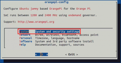
Then select Hardware

Then use the arrow keys on the keyboard to locate the position shown in the figure below, and then use the spacebar to select the SPI configuration you want to open
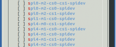
Then select <Save> to save

Then Select <Back>

Then select <Reboot> to restart the system for the configuration to take effect

After restarting, enter the system and check whether there is a device node of spidevx.x in the Linux system. If it exists, it means that SPI has been set up and can be used directly.
orangepi@orangepi:~$ ls /dev/spidev*
/dev/spidev0.0 /dev/spidev0.1 /dev/spidev1.0 /dev/spidev4.0
The above is the result after opening spi0-m2-cs0-cs1-spidev, spi1-m1-cs0-spidev and spi4-m2-cs0-spidev.
Do not short the mosi and miso pins of SPI0, SPI1 or SPI4. The output of running spidev_test is as follows. You can see that the data of TX and RX are inconsistent.
orangepi@orangepi:~$ sudo spidev_test -v -D /dev/spidev0.0 #The command for spi0
orangepi@orangepi:~$ sudo spidev_test -v -D /dev/spidev1.0 #The command for spi1
orangepi@orangepi:~$ sudo spidev_test -v -D /dev/spidev4.0 #The command for spi4
spi mode: 0x0
bits per word: 8
max speed: 500000 Hz (500 KHz)
TX | FF FF FF FF FF FF 40 00 00 00 00 95 FF FF FF FF FF FF FF FF FF FF FF FF FF FF FF FF FF FF F0 0D | ......@.…▒..................▒.
RX | FF FF FF FF FF FF FF FF FF FF FF FF FF FF FF FF FF FF FF FF FF FF FF FF FF FF FF FF FF FF FF FF | ............................….
Then short the mosi and miso pins of SPI0 or SPI4 and run spidev_test. The output is as follows. You can see that the data sent and received are the same.
orangepi@orangepi:~$ sudo spidev_test -v -D /dev/spidev0.0 #The command for spi0
orangepi@orangepi:~$ sudo spidev_test -v -D /dev/spidev1.0 #The command for spi1
orangepi@orangepi:~$ sudo spidev_test -v -D /dev/spidev4.0 #The command for spi4
spi mode: 0x0
bits per word: 8
max speed: 500000 Hz (500 KHz)
TX | FF FF FF FF FF FF 40 00 00 00 00 95 FF FF FF FF FF FF FF FF FF FF FF FF FF FF FF FF FF FF F0 0D | ......@.…▒..................▒.
RX | FF FF FF FF FF FF 40 00 00 00 00 95 FF FF FF FF FF FF FF FF FF FF FF FF FF FF FF FF FF FF F0 0D | ......@.…▒..................▒.


40pin I2C test
As can be seen from the table below, Orange Pi 5 Ultra has four i2c buses: i2c2, i2c4, i2c5 and i2c8
The corresponding pins of the 4 groups of I2C buses in 40 pins are shown in the following table. I2C2_M0 and I2C2_M4 can only use one of them at the same time, not both. They are the same I2C, just connected to different pins. Please do not think that they are two different I2C buses.
| I2C Bus | SDA corresponds to 40pin | SCL corresponds to 40pin | dtbo corresponding configuration |
| I2C2_M0 | Pin 3 | Pin 5 | i2c2-m0 |
| I2C2_M4 | Pin 11 | Pin 13 | i2c2-m4 |
| I2C4_M3 | Pin 15 | Pin 16 | i2c4-m3 |
| I2C5_M2 | Pin 37 | Pin 12 | i2c5-m2 |
| I2C8_M3 | Pin 27 | Pin 28 | i2c8-m3 |
In Linux system, the I2C bus in 40 pins is closed by default and needs to be opened manually before it can be used. The detailed steps are as follows:
First run orangepi-config. Ordinary users should remember to add sudo permissions.
orangepi@orangepi:~$ sudo orangepi-config
Then Select System
Then Select Hardware

Then use the arrow keys on the keyboard to locate the position shown in the figure below, and then use the spacebar to select the I2C configuration you want to open
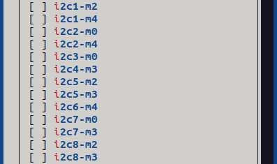
Then select <Save> to save

Then Select <Back>

Then select <Reboot> to restart the system for the configuration to take effect

After starting the Linux system, first confirm that there is a device node that needs to use I2C under /dev
orangepi@orangepi:~$ ls /dev/i2c-*
Then connect an i2c device to the i2c pin of the 40pin connector
Then use the i2cdetect -y command. If the address of the connected i2c device can be detected, it means that i2c can be used normally.
orangepi@orangepi:~$ sudo i2cdetect -y 2 #i2c2 commands
orangepi@orangepi:~$ sudo i2cdetect -y 4 #i2c4 commands
orangepi@orangepi:~$ sudo i2cdetect -y 5 #i2c5 commands
orangepi@orangepi:~$ sudo i2cdetect -y 8 #i2c8 commands
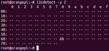

40pin UART test
As can be seen from the table below, the available UARTs of Orange Pi 5 Ultra are uart3, uart4 and uart6, a total of three UART buses. Uart2 is used for debugging serial port functions and is not included.
The corresponding pins of the four UART bus groups in 40 pins are shown in the following table.
| UART Bus | RX corresponds to 40pin | TX corresponds to 40pin | Dtbo corresponding configuration |
| UART3_M1 | Pin 33 | Pin 31 | uart3-m1 |
| UART4_M2 | Pin 19 | Pin 23 | uart4-m2 |
| UART6_M1 | Pin 11 | Pin 13 | uart6-m1 |
In Linux system, the UART in 40 pin is closed by default and needs to be opened manually before it can be used. The detailed steps are as follows:
Ordinary users should remember to add sudo permissions.
orangepi@orangepi:~$ sudo orangepi-config
Then Select System
Then Select Hardware
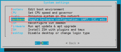
Then use the arrow keys on the keyboard to locate the position shown in the figure below, and then use the spacebar to select the UART configuration you want to open
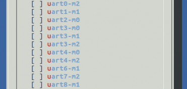
Then select <Save> to save

Then Select<Back>
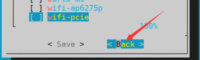
Then select <Reboot> to restart the system for the configuration to take effect

After entering the Linux system, first confirm whether there is a device node corresponding to uart under /dev
orangepi@orangepi:~$ ls /dev/ttyS*
Then start testing the UART interface. First use the Dupont line to short-circuit the rx and tx of the UART interface to be tested.
Use the gpio serial command to test the loopback function of the serial port as shown below. If you can see the following print, it means that the serial port communication is normal (ttySX needs to be replaced with the corresponding uart node name, please do not copy it)
orangepi@orangepi:~$ sudo gpio serial /dev/ttySX
Out: 0: -> 0
Out: 1: -> 1
Out: 2: -> 2
Out: 3: -> 3
Out: 4: -> 4
Out: 5: -> 5^C

How to test PWM using /sys/class/pwm
As can be seen from the table below, Orange Pi 5 Ultra has seven PWM channels: pwm0, pwm1, pwm3, pwm6, pwm12, pwm13 and pwm14
The corresponding pins of PWM in 40pin are shown in the following table. Only one of PWM0_M0 and PWM0_M2, PWM1_M0 and PWM1_M2 can be used at the same time, and they cannot be used at the same time. They are the same PWM, just connected to different pins. Please do not think that they are two different PWM buses.
| PWM Bus | Corresponding to 40pin | Dtbo corresponding configuration |
| PWM0_M0 | Pin 5 | pwm0-m0 |
| PWM0_M2 | Pin 15 | pwm0-m2 |
| PWM1_M0 | Pin 3 | pwm1-m0 |
| PWM1_M2 | Pin 16 | pwm1-m2 |
| PWM3_M3 | Pin 7 | pwm3-m3 |
| PWM6_M1 | Pin 27 | pwm6-m1 |
| PWM12_M0 | Pin 31 | pwm12-m0 |
| PWM13_M0 | Pin 33 | pwm13-m0 |
| PWM14_M0 | Pin 35 | pwm14-m0 |
In Linux system, PWM in 40 pin is disabled by default and needs to be enabled manually. The detailed steps are as follows:
First run orangepi-config. Ordinary users should remember to add sudo permissions.
orangepi@orangepi:~$ sudo orangepi-config
Then select System
Then select Hardware
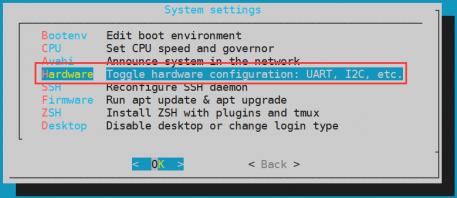
Then use the arrow keys on the keyboard to locate the position shown in the figure below, and then use the spacebar to select the PWM configuration you want to open
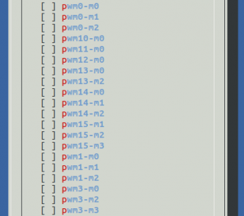
Then select <Save> to save

Then Select <Back>

Then select <Reboot> to restart the system for the configuration to take effect

When a pwm is turned on, there will be an additional pwmchipX in /sys/class/pwm/ (X is a specific number). For example, after turning on pwm3, the pwmchipX under/sys/class/pwm/will change from two to three.
orangepi@orangepi:~$ ls /sys/class/pwm/
pwmchip0 pwmchip1 pwmchip2
Which pwmchip above corresponds to pwm3? Let's first check the output of the ls /sys/class/pwm/ -l command, as shown below:
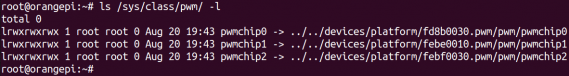
Then from the table below, we can see that the base address of the pwm3 register is fd8b0030. Looking at the output of the ls /sys/class/pwm/ -l command, we can see that pwmchip0 is linked to fd8b0030.pwm, so the pwmchip corresponding to pwm3 is pwmchip0.
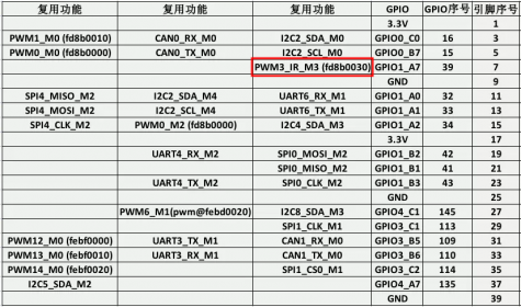
Then use the following command to make pwm3 output a 50Hz square wave (please switch to the root user first, then execute the following command)


root@orangepi:~# echo 0 > /sys/class/pwm/pwmchip0/export
root@orangepi:~# echo 20000000 > /sys/class/pwm/pwmchip0/pwm0/period
root@orangepi:~# echo 1000000 > /sys/class/pwm/pwmchip0/pwm0/duty_cycle
root@orangepi:~# echo 1 > /sys/class/pwm/pwmchip0/pwm0/enable

- The pwm3 test method demonstrated above is similar to other pwm test methods.
CAN test methods
Only the Linux 5.10 kernel image supports the CAN function, while the Linux 6.1 kernel image does not support it.
How to open CAN
As can be seen from the table below, the available CAN buses for Orange Pi 5 Ultra are CAN0 and CAN1
In Linux system, CAN in 40 pin is closed by default and needs to be opened manually before it can be used. The detailed steps are as follows:
First run orangepi-config. Ordinary users should remember to add sudo permissions.
orangepi@orangepi:~$ sudo orangepi-config
Then select System
Then select Hardware
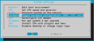
Then use the arrow keys on the keyboard to locate the position shown in the figure below, and then use the spacebar to select the configuration you want to open

Then select <Save> to save

Then select <Back>

Then select <Reboot> to restart the system to make the configuration take effect
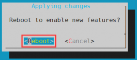
After entering the Linux system, use the sudo ifconfig -a command. If you can see the CAN device, it means that CAN has been correctly opened.
orangepi@orangepi:~$ sudo ifconfig -a
can0: flags=128<NOARP> mtu 16
unspec 00-00-00-00-00-00-00-00-00-00-00-00-00-00-00-00 txqueuelen 10 (UNSPEC)
RX packets 0 bytes 0 (0.0 B)
RX errors 0 dropped 0 overruns 0 frame 0
TX packets 0 bytes 0 (0.0 B)
TX errors 0 dropped 0 overruns 0 carrier 0 collisions 0
device interrupt 91
can1: flags=128<NOARP> mtu 16
unspec 00-00-00-00-00-00-00-00-00-00-00-00-00-00-00-00 txqueuelen 10 (UNSPEC)
RX packets 0 bytes 0 (0.0 B)
RX errors 0 dropped 0 overruns 0 frame 0
TX packets 0 bytes 0 (0.0 B)
TX errors 0 dropped 0 overruns 0 carrier 0 collisions 0
device interrupt 92
The pins corresponding to CAN0 and CAN1 are
| CAN0 | CAN1 | |
| TX Pin | Corresponding to pin 5 | Corresponding to pin 33 |
| RX Pin | Corresponding to pin 3 | Corresponding to pin 31 |
Using CANalyst-II analyzer to test the sending and receiving messages
The CANalyst-II analyzer used in the test is shown in the figure below

CANalyst-II analyzer data download link
First, you need to install the USBCANToolSetup software
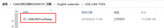
The shortcut after USBCANToolSetup is installed is:

You also need to install the USB driver
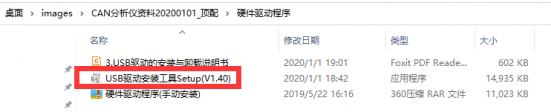
The USB port of CANalyst-II analyzer needs to be connected to the USB port of the computer.

To test the CAN function, you also need to prepare a CAN transceiver as shown in the figure below. The main function of the CAN transceiver is to convert the TTL signal of the CAN controller into the differential signal of the CAN bus.
The 3.3V pin of the CAN transceiver needs to be connected to the 3.3V pin of the 40pin of the development board
The GND pin of the CAN transceiver needs to be connected to the GND pin of the 40pin of the development board
The CAN TX pin of the CAN transceiver needs to be connected to the TX pin of the CAN bus in the 40pin of the development board
The CAN RX pin of the CAN transceiver needs to be connected to the RX pin of the CAN bus in the 40pin of the development board
The CANH pin of the CAN transceiver needs to be connected to the H interface of the analyzer
The CANL pin of the CAN transceiver needs to be connected to the L interface of the analyzer

Then you can open the USB-CAN software
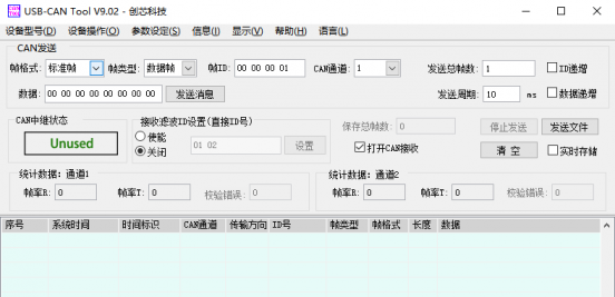
Then click Start Device
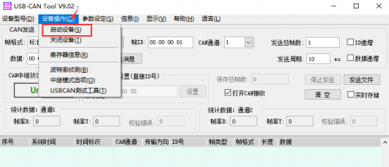
Then click OK
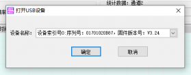
Set the baud rate to 1000k bps
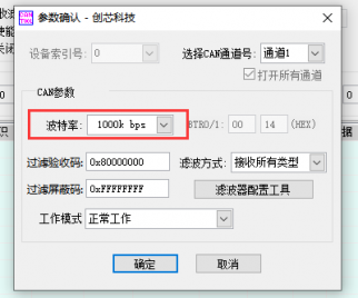
After successfully opening, the USB-CAN software will display the serial number and other information
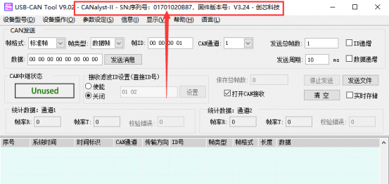
Development board receives CAN message test
First, set the baud rate of the CAN bus to 1000kbps in the Linux system of the development board
orangepi@orangepi:~$ sudo ip link set can0 down
orangepi@orangepi:~$ sudo ip link set can0 type can bitrate 1000000
orangepi@orangepi:~$ sudo ip link set can0 up
Then run the candump can0 command to prepare to receive messages.
orangepi@orangepi:~$ sudo candump can0
Then send a message to the development board in the USB-CAN software
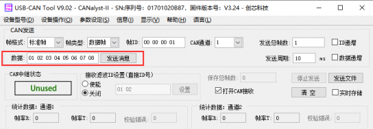
If the development board can receive the message sent by the analyzer, it means that the CAN bus can be used normally.
orangepi@orangepi5ultra:~$ sudo candump can0
can0 001 [8] 01 02 03 04 05 06 07 08
Development board sends CAN message test
First, set the CAN baud rate to 1000kbps in the Linux system
orangepi@orangepi:~$ sudo ip link set can0 down
orangepi@orangepi:~$ sudo ip link set can0 type can bitrate 1000000
orangepi@orangepi:~$ sudo ip link set can0 up
Execute the cansend command in the development board to send a message
orangepi@orangepi:~$ sudo cansend can0 123#1122334455667788
If the USB-CAN software can receive the message sent by the development board, it means the communication is successful
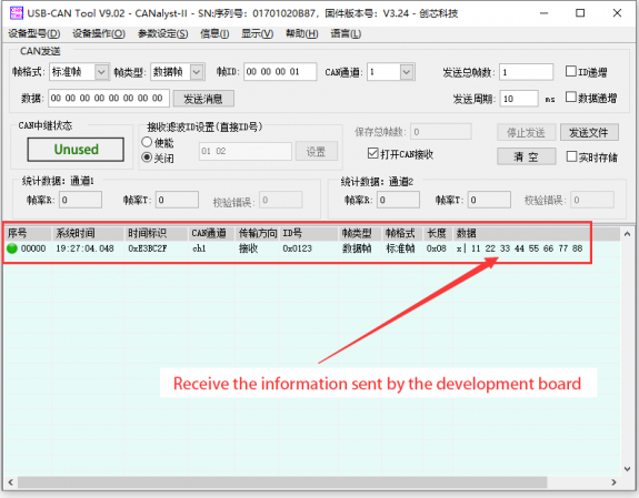


How to use wiringOP hardware PWM
Before using wiringOP to operate PWM, please make sure that wiringOP has been installed on the Linux system. If the gpio readall command can be used normally, it means that wiringOP has been installed. If it prompts that the command cannot be found, please refer to the instructions in the section "How to install wiringOP" to install wiringOP first.
How to set PWM using wiringOP's gpio command
Set the corresponding pin to PWM mode
As shown in the following table, the development board can use seven PWMs, namely PWM0, PWM1, PWM3, PWM6, PWM12, PWM13 and PWM14. Only one of PWM0_M0 and PWM0_M2, PWM1_M0 and PWM1_M2 can be used at the same time, and they cannot be used at the same time. They are the same PWM, but connected to different pins. Please do not think that they are two different PWM buses.
The wPi numbers corresponding to the PWM pins are as follows:
| PWM Pin | wPi Serial number | Pin number | GPIO number |
| PWM0_M0 | 1 | 5 | 15 |
| PWM0_M2 | 8 | 15 | 34 |
| PWM1_M0 | 0 | 3 | 16 |
| PWM1_M2 | 9 | 16 | 35 |
| PWM3_M3 | 2 | 7 | 39 |
| PWM6_M1 | 17 | 27 | 145 |
| PWM12_M0 | 20 | 31 | 109 |
| PWM13_M0 | 22 | 33 | 110 |
| PWM14_M0 | 23 | 35 | 114 |
The command to set the pin to PWM mode is as follows, taking PWM0_M0 as an example, where the third parameter needs to enter the wPi number corresponding to the PWM0_M0 pin.
orangepi@orangepi:~$ gpio mode 1 pwm
After the pin is set to PWM mode, it will output a square wave with a frequency of 200Hz, a period of 5ms, and a duty cycle of 50% by default. At this time, we use an oscilloscope to measure the corresponding PWM pin and we can see the following waveform.

Methods for adjusting PWM frequency
The calculation formula of PWM frequency is as follows:
PWM frequency = clock frequency / (frequency division factor * value of period register)
Among them:
1. The default value of the clock frequency is 24000000Hz.
2. The value range of the frequency division coefficient is an even number between 2 and 512, and the default value is 120. If the frequency division coefficient is set to an odd number, the actual frequency division coefficient is the set value minus one.
3. The default value of the period register is 1000.
4. The default value of the PWM frequency is 24000000 / (120 * 1000) = 200Hz.
Method of adjusting PWM frequency by setting the frequency division factor
We can use the following command to set the division factor of the PWM0_M0 pin to 4.
orangepi@orangepi:~$ gpio pwmc 1 4
According to the above formula, the calculated value of PWM frequency is 6000Hz. Through the oscilloscope, it can be observed that the measured value of PWM frequency is 6010Hz, and the error can be ignored.

Direct method to set PWM frequency
We can use the gpio pwmTone command to set the frequency of the PWM pin. For example, the following command can be used to set the PWM frequency of the PWM0_M0 pin to 500Hz.
orangepi@orangepi:~$ gpio pwmTone 1 500
When setting the PWM frequency, you need to ensure that:
The set frequency value is < 24000000 / (frequency division factor * 2).
For example, the default division factor is 120. If the division factor is not modified, the set frequency value should be less than 100000 Hz.
If the value is set too large, the following error message will appear:
gpio: The PWM frequency you set is too high to be possible
Then through the oscilloscope, it can be observed that the PWM frequency becomes 500Hz.
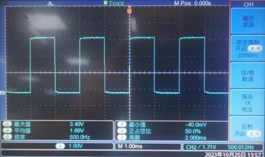

Methods for adjusting PWM duty cycle
The calculation formula of PWM duty cycle is as follows. We can adjust the PWM duty cycle by setting the value of the duty cycle register and the value of the period register.
PWM duty cycle = value of duty cycle register / value of period register
Where:
The default value of the duty cycle register is 500.
The default value of the period register is 1000.
It should be noted that the value of the duty cycle register needs to be smaller than the value of the period register because the duty cycle cannot be greater than 1.
When the value of the duty cycle register is set to be greater than the value of the period register, the following error message will be displayed:
gpio: CCR should be less than or equal to ARR (XXX)
When the value of the period register is set to < the value of the duty cycle register, the following error message will be prompted:
gpio: ARR should be greater than or equal to CRR (XXX)
We can use the following command to set the value of the period register of the PWM0_M0 pin to 2000.
orangepi@orangepi:~$ gpio pwmr 1 2000
After running the above command, you can observe through the oscilloscope that the PWM duty cycle changes from the default 50% (500/1000) to 25% (500/2000).

We can use the following command to set the duty cycle register value of the PWM0_M0 pin to 1000.
orangepi@orangepi:~$ gpio pwm 1 1000
After running the above command, you can observe through the oscilloscope that the PWM duty cycle changes from 25% (500/2000) to 50% (1000/2000).
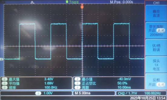


How to use the PWM test program
In the example directory of wiringOP, there is a program called pwm.c, which demonstrates how to use the PWM-related API in wiringOP to operate PWM.
orangepi@orangepi:~$ cd /usr/src/wiringOP/examples/
orangepi@orangepi:/usr/src/wiringOP/examples$ ls pwm.c
pwm.c
The command to compile pwm.c into an executable program is as follows:
orangepi@orangepi:/usr/src/wiringOP/examples$ gcc -o pwm pwm.c -lwiringPi
Then you can execute the PWM test program. When executing the PWM test program, you need to specify the PWM pin. For example, you can use the following command to test the PWM0_M0 pin:
orangepi@orangepi:/usr/src/wiringOP/examples$ sudo ./pwm 1
After the pwm program is executed, the following contents will be tested in sequence:
Adjust the PWM duty cycle by setting the value of the period register.
Adjust the PWM duty cycle by setting the value of the duty cycle register.
Adjust the PWM frequency by setting the division factor.
Set the PWM frequency directly.
After each test is completed, the PWM waveform output will stop for 5 seconds. After all test contents are completed, a new round of testing will start again.
The detailed execution process of the PWM test program is as follows:
Adjust the PWM duty cycle by setting the value of the period register: Through the oscilloscope, it can be observed that the PWM waveform changes every 0.5 seconds. After changing 8 times, the PWM duty cycle changes from 50% to 25% and remains for 5 seconds. Then the PWM waveform changes every 0.5 seconds. After changing 8 times, the PWM duty cycle changes from 25% to 50% and remains for 5 seconds.
Adjust the PWM duty cycle by setting the value of the duty cycle register: Through the oscilloscope, it can be observed that the PWM waveform changes every 0.5 seconds. After changing 8 times, the PWM duty cycle changes from 50% to 100% and remains for 5 seconds. Then the PWM waveform changes every 0.5 seconds. After changing 8 times, the PWM duty cycle changes from 100% to 50% and remains for 5 seconds.
Adjust the PWM frequency by setting the division factor: Through the oscilloscope, it can be observed that the PWM waveform changes every 0.5 seconds. After changing 9 times, the PWM frequency will change from 2000hz to 200hz and maintain for 5 seconds. Then the PWM waveform changes every 0.5 seconds. After changing 9 times, the PWM frequency will become 2000Hz and maintain for 5 seconds.
Directly set the PWM frequency: Through the oscilloscope, it can be observed that the PWM frequency first changes to 2000Hz, and then increases by 2000Hz every two seconds. After changing 9 times, the PWM frequency becomes 20000Hz and remains for 5 seconds.
Installation and use of wiringOP-Python
wiringOP-Python is the Python version of wiringOP, which is used to operate the GPIO, I2C, SPI, UART and other hardware resources of the development board in Python programs.
Also note that some of the following commands are performed under the root user.
Installation of wiringOP-Python
First install the dependency package
root@orangepi:~# sudo apt-get update
root@orangepi:~# sudo apt-get -y install git swig python3-dev python3-setuptools
Then use the following command to download the source code of wiringOP-Python
Note that the following git clone --recursive command will automatically download the source code of wiringOP, because wiringOP-Python depends on wiringOP. Please make sure that there are no errors during the download process due to network problems.
If you have problems downloading the code from GitHub, you can directly use the wiringOP-Python source code that comes with the Linux image, which is stored in /usr/src/wiringOP-Python.
root@orangepi:~# git clone --recursive https://github.com/orangepi-xunlong/wiringOP-Python -b next
root@orangepi:~# cd wiringOP-Python
root@orangepi:~/wiringOP-Python# git submodule update --init --remote
Then use the following command to compile wiringOP-Python and install it into the Linux system of the development board
root@orangepi:~# cd wiringOP-Python
root@orangepi:~/wiringOP-Python# python3 generate-bindings.py > bindings.i
root@orangepi:~/wiringOP-Python# sudo python3 setup.py install
Then enter the following command. If help information is output, it means wiringOP-Python has been successfully installed. Press the q key to exit the help information interface.
root@orangepi:~/wiringOP-Python# python3 -c "import wiringpi; help(wiringpi)"
Help on module wiringpi:
NAME
wiringpi
DESCRIPTION
- This file was automatically generated by SWIG (http://www.swig.org).
- Version 4.0.2
- Do not make changes to this file unless you know what you are doing--modify
- the SWIG interface file instead.
The steps to test whether wiringOP-Python is successfully installed in the python command line are as follows:
- First use the python3 command to enter the python3 command line mode
root@orangepi:~# python3
- Then import the Python module of wiringPi
>>> import wiringpi;
- Finally, enter the following command to view the help information of wiringOP-Python. Press the q key to exit the help information interface.
>>> help(wiringpi)
Help on module wiringpi:
NAME
wiringpi
DESCRIPTION
- This file was automatically generated by SWIG (http://www.swig.org).
- Version 4.0.2
- Do not make changes to this file unless you know what you are doing--modify
- the SWIG interface file instead.
CLASSES
builtins.object
GPIO
I2C
Serial
nes
class GPIO(builtins.object)
| GPIO(pinmode=0)
|
>>>
40pin GPIO port test
WiringOP-Python is the same as wiringOP. It can also determine which GPIO pin to operate by specifying the wPi number. Because there is no command to view the wPi number in wiringOP-Python, the correspondence between the board's wPi number and the physical pin can only be viewed through the gpio command in wiringOP.
Below, we take pin 7, which corresponds to GPIO GPIO1_A7 and wPi number 2, as an example to demonstrate how to set the high and low levels of the GPIO port.
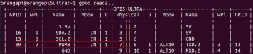
The steps for testing directly using commands are as follows:
First, set the GPIO port to output mode. The first parameter of the pinMode function is the wPi number corresponding to the pin, and the second parameter is the GPIO mode.
root@orangepi:~/wiringOP-Python# python3 -c "import wiringpi; \
from wiringpi import GPIO; wiringpi.wiringPiSetup() ; \
wiringpi.pinMode(2, GPIO.OUTPUT) ; "
Then set the GPIO port to output a low level. After setting, you can use a multimeter to measure the voltage value of the pin. If it is 0v, it means that the low level is set successfully.
root@orangepi:~/wiringOP-Python# python3 -c "import wiringpi; \
from wiringpi import GPIO; wiringpi.wiringPiSetup() ;\
wiringpi.digitalWrite(2, GPIO.LOW)"
Then set the GPIO port to output a high level. After setting, you can use a multimeter to measure the voltage value of the pin. If it is 3.3v, it means that the high level is set successfully.
root@orangepi:~/wiringOP-Python# python3 -c "import wiringpi; \
from wiringpi import GPIO; wiringpi.wiringPiSetup() ;\
wiringpi.digitalWrite(2, GPIO.HIGH)"
The steps to test in the python3 command line are as follows:
First use the python3 command to enter the python3 command line mode
root@orangepi:~# python3
Then import the Python module of wiringPi
>>> import wiringpi
>>> from wiringpi import GPIO
Then set the GPIO port to output mode, where the first parameter of the pinMode function is the wPi number corresponding to the pin, and the second parameter is the GPIO mode
>>> wiringpi.wiringPiSetup()
0
>>> wiringpi.pinMode(2, GPIO.OUTPUT)
Then set the GPIO port to output a low level. After setting, you can use a multimeter to measure the voltage value of the pin. If it is 0v, it means that the low level is set successfully.
>>> wiringpi.digitalWrite(2, GPIO.LOW)
Then set the GPIO port to output a high level. After setting, you can use a multimeter to measure the voltage value of the pin. If it is 3.3v, it means that the high level is set successfully.
>>> wiringpi.digitalWrite(2, GPIO.HIGH)
wiringOP-Python For setting the GPIO high and low levels in Python code, please refer to the blink.py test program in the examples. The blink.py test program will set the voltage of all GPIO ports in the 26 pins of the development board to change continuously.
root@orangepi:~/wiringOP-Python# cd examples
root@orangepi:~/wiringOP-Python/examples# ls blink.py
blink.py
root@orangepi:~/wiringOP-Python/examples# python3 blink.py
40pin SPI test
As shown in the figure below, the available spis for Orange Pi 5 Ultra are spi0, spi1 and spi4
The corresponding pins of SPI0, SPI1 and SPI4 in 40 pins are shown in the following table.
| SPI0_M2 correspond 40pin | SPI1_M1 correspond 40pin | SPI4_M2 correspond 40pin | |
| MOSI | Pin 19 | Pin 40 | Pin 13 |
| MISO | Pin 21 | Pin 38 | Pin 11 |
| CLK | Pin 23 | Pin 29 | Pin 15 |
| CS0 | Pin 24 | Pin 35 | Pin 16 |
| CS1 | Pin 26 | None | None |
| Dtbo confi guration | spi 0-m2-cs0-spidev
spi 0-m2-cs1-spidev spi0-m2 -cs0-cs1-spidev |
spi1 -m1-cs0-spidev | spi4 -m2-cs0-spidev |
In Linux system, the SPI in 40 pin is closed by default and needs to be opened manually before it can be used. The detailed steps are as follows:
First run orangepi-config. Ordinary users should remember to add sudo permissions.
orangepi@orangepi:~$ sudo orangepi-config
Then select System
Then select Hardware
Then use the arrow keys on the keyboard to locate the position shown in the figure below, and then use the spacebar to select the SPI configuration you want to open
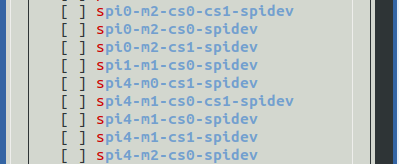
Then select <Save> to save

Then select <Back>
Then select <Reboot> to restart the system for the configuration to take effect
After restarting, enter the system and check whether there is a device node of spidevx.x in the Linux system. If it exists, it means that SPI has been set up and can be used directly.
orangepi@orangepi:~$ ls /dev/spidev*
/dev/spidev0.0 /dev/spidev0.1 /dev/spidev4.0
The above is the result displayed after opening spi0-m2-cs0-cs1-spidev and spi4-m2-cs0-spidev.
Then you can use the spidev_test.py program in the examples to test the SPI loopback function. The spidev_test.py program needs to specify the following two parameters:
--channel:Specify the SPI channel number
--port:Specify the SPI port number
Without shorting the mosi and miso pins of SPI, the output of running spidev_test.py is as follows. It can be seen that the data of TX and RX are inconsistent.
The x after the --channel and --port parameters needs to be replaced with the specific SPI channel number and SPI port number.
root@orangepi:~/wiringOP-Python# cd examples
root@orangepi:~/wiringOP-Python/examples# python3 spidev_test.py --channel x --port x
spi mode: 0x0
max speed: 500000 Hz (500 KHz)
Opening device /dev/spidev0.0
TX | FF FF FF FF FF FF 40 00 00 00 00 95 FF FF FF FF FF FF FF FF FF FF FF FF FF FF FF FF FF FF F0 0D |......@.......…|
RX | FF FF FF FF FF FF FF FF FF FF FF FF FF FF FF FF FF FF FF FF FF FF FF FF FF FF FF FF FF FF FF FF |.............….|
Then use the Dupont line to short the SPI's txd and rxd pins and run spidev_test.py. The output is as follows. You can see that the sent and received data are the same, indicating that the SPI loopback test is normal.
The x after the --channel and --port parameters needs to be replaced with the specific SPI channel number and SPI port number.
root@orangepi:~/wiringOP-Python# cd examples
root@orangepi:~/wiringOP-Python/examples# python3 spidev_test.py --channel x --port x
spi mode: 0x0
max speed: 500000 Hz (500 KHz)
Opening device /dev/spidev0.0
TX | FF FF FF FF FF FF 40 00 00 00 00 95 FF FF FF FF FF FF FF FF FF FF FF FF FF FF FF FF FF FF F0 0D |......@.......…|
RX | FF FF FF FF FF FF 40 00 00 00 00 95 FF FF FF FF FF FF FF FF FF FF FF FF FF FF FF FF FF FF F0 0D |......@.......…|
4.40pin I2C test
As can be seen from the table below, Orange Pi 5 Ultra has four i2c buses: i2c2, i2c4, i2c5 and i2c8
The corresponding pins of the 4 groups of I2C buses in 40 pins are shown in the following table. I2C2_M0 and I2C2_M4 can only use one of them at the same time, not both. They are the same I2C, just connected to different pins. Please do not think that they are two different I2C buses.
| I2C bus | SDA corresponds to 40pin | SCL corresponds to 40pin | dtbo corresponding configuration |
| I2C2_M0 | Pin 3 | Pin 5 | i2c2-m0 |
| I2C2_M4 | Pin 11 | Pin 13 | i2c2-m4 |
| I2C4_M3 | Pin 15 | Pin 16 | i2c4-m3 |
| I2C5_M2 | Pin 37 | Pin 12 | i2c5-m2 |
| I2C8_M3 | Pin 27 | Pin 28 | i2c8-m3 |
In Linux system, the I2C bus in 40 pins is closed by default and needs to be opened manually before it can be used. The detailed steps are as follows:
First run orangepi-config. Ordinary users should remember to add sudo permissions.
orangepi@orangepi:~$ sudo orangepi-config
Then select System
Then select Hardware
Then use the arrow keys on the keyboard to locate the position shown in the figure below, and then use the spacebar to select the I2C configuration you want to open
Then select <Save> to save
Then select <Back>
Then select <Reboot> to restart the system for the configuration to take effect
After starting the Linux system, first confirm that the i2c device node exists under /dev
orangepi@orangepi:~$ ls /dev/i2c-*
Then connect an i2c device to the i2c pin of the 40pin connector. Here we take the ds1307 RTC module as an example.

Then use the i2cdetect -y command. If the address of the connected i2c device can be detected, it means that i2c can be used normally.
orangepi@orangepi:~$ sudo i2cdetect -y 2 #i2c2 commands
orangepi@orangepi:~$ sudo i2cdetect -y 4 #i2c4 commands
orangepi@orangepi:~$ sudo i2cdetect -y 5 #i2c5 commands
orangepi@orangepi:~$ sudo i2cdetect -y 8 #i2c8 commands


Then you can run the ds1307.py test program in the examples to read the RTC time.
root@orangepi:~/wiringOP-Python# cd examples
root@orangepi:~/wiringOP-Python/examples# python3 ds1307.py --device /dev/i2c-2
Thu 2023-01-05 14:57:55
Thu 2023-01-05 14:57:56
Thu 2023-01-05 14:57:57
^C
exit
40pin UART test
As can be seen from the table below, the available UARTs of Orange Pi 5 Ultra are uart3, uart4 and uart6, a total of three UART buses. Uart2 is used for debugging serial port functions and is not included.
The corresponding pins of the four UART buses in 40 pins are shown in the following table:
| UART bus | RX correspond 40pin | TX correspond 40pin | Dtbo Corresponding configuration |
| UART3_M1 | Pin 33 | Pin 31 | uart3-m1 |
| UART4_M2 | Pin 19 | Pin 23 | uart4-m2 |
| UART6_M1 | Pin 11 | Pin 13 | uart6-m1 |
In Linux system, the UART in 40 pin is closed by default and needs to be opened manually before it can be used. The detailed steps are as follows:
First run orangepi-config. Ordinary users should remember to add sudo permissions.
orangepi@orangepi:~$ sudo orangepi-config
Then select System

Then select Hardware
Then use the arrow keys on the keyboard to locate the position shown in the figure below, and then use the spacebar to select the UART configuration you want to open
Then select <Save> to save
Then select <Back>
Then select <Reboot> to restart the system for the configuration to take effect
After entering the Linux system, first confirm whether there is a device node corresponding to uart under /dev
orangepi@orangepi:~$ ls /dev/ttyS*
Then start testing the UART interface. First use the Dupont line to short-circuit the rx and tx of the UART interface to be tested.
Use the serialTest.py program in the examples to test the loopback function of the serial port as shown below. If you can see the following print, it means that the serial port communication is normal.
The X in /dev/ttySX needs to be replaced with the serial number of the specific uart device node.
root@orangepi:~/wiringOP-Python/examples# python3 serialTest.py --device /dev/ttySX
Out: 0: -> 0
Out: 1: -> 1
Out: 2: -> 2
Out: 3: -> 3
Out: 4:^C
exit
Hardware watchdog test
The Linux system released by Orange Pi has the watchdog_test program pre-installed, which can be used for direct testing.
The method to run the watchdog_test program is as follows:
The second parameter 10 represents the watchdog count time. If the watchdog is not fed within this time, the system will restart.
We can feed the dog by pressing any key on the keyboard (except ESC). After feeding the dog, the program will print a line of keep alive to indicate that the dog was successfully fed.
orangepi@orangepi:~$ sudo watchdog_test 10
open success
options is 33152,identity is sunxi-wdt
put_usr return,if 0,success:0
The old reset time is: 16
return ENOTTY,if -1,success:0
return ENOTTY,if -1,success:0
put_user return,if 0,success:0
put_usr return,if 0,success:0
keep alive
keep alive
keep alive
Check the serial number of the RK3588 chip
The command to view the serial number of the RK3588 chip is as follows. The serial number of each chip is different, so the serial number can be used to distinguish multiple development boards.
orangepi@orangepi:~$ cat_serial.sh
Serial : 1404a7682e86830c
How to install Docker
The Linux image provided by Orange Pi has Docker pre-installed, but the Docker service is not enabled by default.
Use the enable_docker.sh script to enable the docker service, then you can start using the docker command, and the docker service will be automatically started the next time you start the system
orangepi@orangepi:~$ enable_docker.sh
Then you can use the following command to test docker. If you can run hello-world, it means that docker can be used normally.
orangepi@orangepi:~$ sudo docker run hello-world
Unable to find image 'hello-world:latest' locally
latest: Pulling from library/hello-world
256ab8fe8778: Pull complete
Digest: sha256:7f0a9f93b4aa3022c3a4c147a449ef11e0941a1fd0bf4a8e6c9408b2600777c5
Status: Downloaded newer image for hello-world:latest
Hello from Docker!
This message shows that your installation appears to be working correctly.
.….
How to download and install the arm64 version of balenaEtcher
The download address of balenaEtcher arm64 version is:
The download address of the deb installation package is as follows, which needs to be installed before use
The download address of the AppImage version that does not require installation is as follows:

How to install and use the deb version of balenaEtcher:
deb version of balenaEtcher installation command is as follows:
orangepi@orangepi:~$ sudo apt install -y --fix-broken ./balena-etcher-electron_1.7.9+5945ab1f_arm64.deb
After the deb version of balenaEtcher is installed, you can open it in Application

balenaEtcher opens with the following interface:

How to use the AppImage version of balenaEtcher:
First add permissions to balenaEtcher
orangepi@orangepi:~/Desktop$ chmod +x balenaEtcher-1.7.9+5945ab1f-arm64.AppImage
Then select the AppImage version of balenaEtcher, right-click, and click Execute to open balenaEtcher.
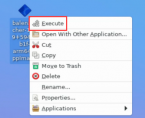

How to install Baota Linux Panel
Baota Linux Panel is a server management software that improves operation and maintenance efficiency. It supports more than 100 server management functions such as one-click LAMP/LNMP/cluster/monitoring/website/FTP/database/JAVA (excerpted from Baota official website)
The recommended order of Baota Linux system compatibility is:
Debian11 > Ubuntu 22.04 > Debian12
Then enter the following command in the Linux system to start the installation of the pagoda
orangepi@orangepi:~$ sudo install_bt_panel.sh
Then the Baota installation program will prompt whether to install Bt-Panel to the /www folder, just enter y
+----------------------------------------------------------------------
| Bt-WebPanel FOR CentOS/Ubuntu/Debian
+----------------------------------------------------------------------
| Copyright © 2015-2099 BT-SOFT(http://www.bt.cn) All rights reserved.
+----------------------------------------------------------------------
| The WebPanel URL will be http://SERVER_IP:8888 when installed.
+----------------------------------------------------------------------
Do you want to install Bt-Panel to the /www directory now?(y/n): y
Then all you have to do is wait patiently. When you see the following print information output by the terminal, it means that the pagoda has been installed. The entire installation process takes about 6 minutes, which may vary depending on the network speed.
==================================================================
Congratulations! Installed successfully!
=============When you open the panel browser for the first time, it will prompt that it is not safe=================
Please choose one of the following ways to resolve the unsafe reminder
1、Download the certificate, address: https://dg2.bt.cn/ssl/baota_root.pfx, double-click to install, password [www.bt.cn]
2、Click [Advanced] - [Continue] or [Accept the risk and continue] to access
Tutorial: https://www.bt.cn/bbs/thread-117246-1-1.html
Mac users please download and use this certificate: https://dg2.bt.cn/ssl/mac.crt
========================Panel account login information==========================
[Cloud Server] Please allow port 31402 in the security group
External panel address: https://183.17.125.22:31402/d1f7cff0
Intranet panel address: https://10.31.2.175:31402/d1f7cff0
username: a8vazvbh
password: bc7bb4b7
Use the browser to access the following link to add Baota customer service
https://www.bt.cn/new/wechat_customer
==================================================================
Time consumed: 14 Minute!
At this time, enter the panel address shown above in the browser to open the login interface of the Baota Linux panel, and then enter the username and password shown in the above figure in the corresponding position to log in to Baota
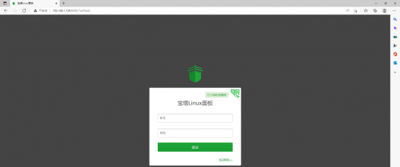
After successfully logging into the pagoda, the following welcome interface will pop up. First, please read the user instructions in the middle and drag them to the bottom. Then you can select "I have agreed and read the User Agreement", and then click "Enter the Panel" to enter the pagoda.
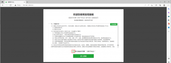
After entering the pagoda, you will be prompted to bind an account on the pagoda official website. If you don’t have an account, you can go to the pagoda’s official website (https://www.bt.cn) to register one.

The final interface is shown in the figure below. You can intuitively see some status information of the development board Linux system, such as load status, CPU usage, memory usage, and storage space usage.
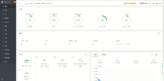
Test the SSH terminal login of Baota
After opening the SSH terminal of Baota, you will be prompted to enter the password of the development board system. At this time, enter orangepi in the password box (the default password, if you have changed it, please fill in the modified password)
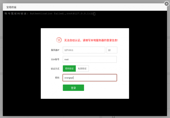
The display after successful login is as shown below
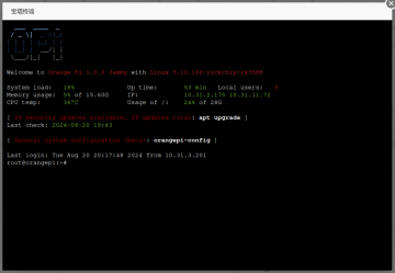
You can install Apache, MySQL, PHP and other software in Baota's software store, and you can also deploy various applications with one click. Please explore these functions by yourself, and I will not demonstrate them one by one here.
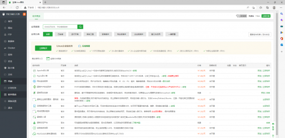
For more functions of the pagoda, please refer to the following information to explore it yourself
User Manual:http://docs.bt.cn
Forum Address:https://www.bt.cn/bbs
GitHub Link:https://github.com/aaPanel/BaoTa


Set up Chinese environment and install Chinese input method
Note: Before installing the Chinese input method, please make sure that the Linux system used by the development board is the desktop version.
Installation method of Debian system
First set the default locale to Chinese
Enter the following command to start configuring locale
orangepi@orangepi:~$ sudo dpkg-reconfigure locales
Then select zh_CN.UTF-8 UTF-8 in the pop-up interface (use the up and down arrow keys on the keyboard to move up and down, use the space bar to select, and finally use the Tab key to move the cursor to <OK>, then press Enter)
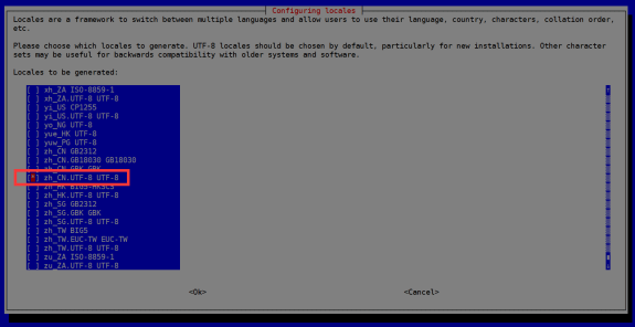
Then set the default locale to zh_CN.UTF-8
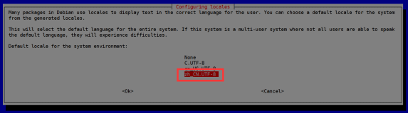
After exiting the interface, the locale setting will begin. The output displayed on the command line is as follows
orangepi@orangepi:~$ sudo dpkg-reconfigure locales
Generating locales (this might take a while)...
en_US.UTF-8... done
zh_CN.UTF-8... done
Generation complete.
Then open Input Method

Then select OK
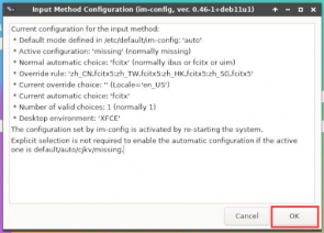
Then select Yes
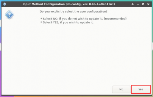
Then select fcitx
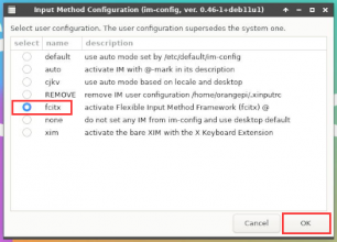
Then select OK
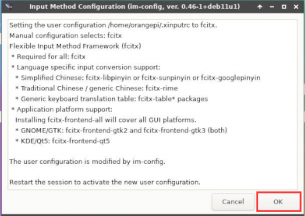
Then restart the Linux system to make the configuration take effect
Then open Fcitx configuration

Then click the + sign in the position shown in the picture below
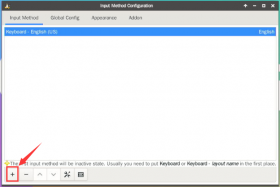
Then search Google Pinyin and click OK
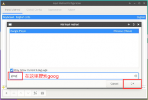


Note: If you can't see the Google Pinyin option, please try to remove the √ in front of Only Show Current Languageq.
Then put Google Pinyin at the front
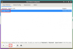
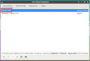
Then open the Geany editor to test the Chinese input method

The Chinese input method test is as follows
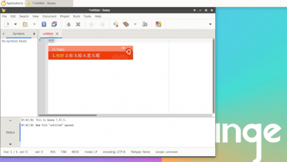
Use the Ctrl+Space shortcut key to switch between Chinese and English input methods
If you need the entire system to display in Chinese, you can set the variables in /etc/default/locale to zh_CN.UTF-8
orangepi@orangepi:~$ sudo vim /etc/default/locale
# File generated by update-locale
LC_MESSAGES=zh_CN.UTF-8
LANG=zh_CN.UTF-8
LANGUAGE=zh_CN.UTF-8
Then restart the system and you will see that the system is displayed in Chinese


How to install Ubuntu 20.04 system
First open Language Support

Then find the Chinese (China) option
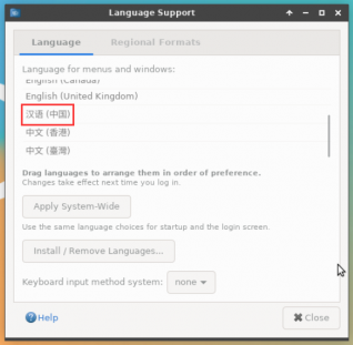
Then use the left mouse button to select Chinese (China) and hold it down, then drag it upwards to the starting position. The display after dragging is as shown below:
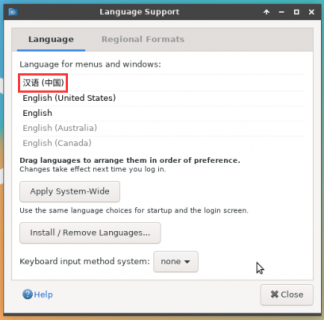


Note that this step is not easy to drag, please be patient and try a few more times.
Then select Apply System-Wide to apply the Chinese settings to the entire system
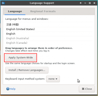
Then set the Keyboard input method system to fcitx
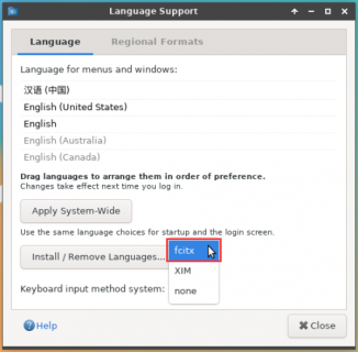
Then restart the Linux system to make the configuration take effect
After re-entering the system, please select "Do not ask me again" in the following interface, and then decide whether to update the standard folder to Chinese according to your own preferences.
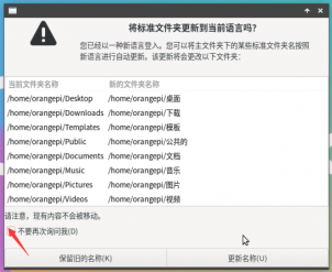
Then you can see that the desktop is displayed in Chinese

Then we can open Geany to test the Chinese input method. The opening method is as shown in the figure below

After opening Geany, the default input method is still English. We can switch to Chinese input method by pressing Ctrl+Space, and then we can input Chinese.
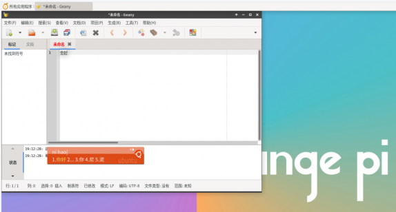


Installation method for Ubuntu 22.04 system
First open Language Support
Then find the Chinese (China) option
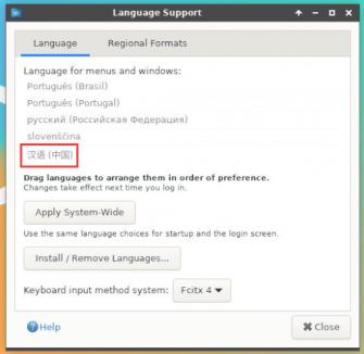
Then use the left mouse button to select Chinese (China) and hold it down, then drag it upwards to the starting position. The display after dragging is as shown below:
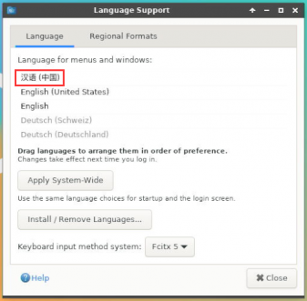


Note that this step is not easy to drag, please be patient and try a few more times.
Then select Apply System-Wide to apply the Chinese settings to the entire system
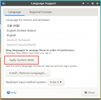
Then restart the Linux system to make the configuration take effect
After re-entering the system, please select "Do not ask me again" in the following interface, and then decide whether to update the standard folder to Chinese according to your own preferences.
Then you can see that the desktop is displayed in Chinese
Then open the Fcitx5 configuration program

Then select Pinyin input method
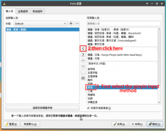
The interface after selection is as shown below, then click OK
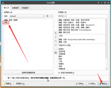
Then we can open Geany to test the Chinese input method. The opening method is as shown in the figure below
After opening Geany, the default input method is still English. We can switch to Chinese input method by pressing Ctrl+Space, and then we can input Chinese.


How to remotely log in to the Linux system desktop
The Ubuntu Gnome Wayland image does not support remote desktop login using Nomachine and VNC as described here.
Remote login using NoMachine
Please make sure that the Ubuntu or Debian system installed on the development board is a desktop version. In addition, NoMachine also provides detailed usage documentation. It is strongly recommended to read this document to familiarize yourself with the use of NoMachine. The document link is as follows:
https://knowledgebase.nomachine.com/DT10R00166
NoMachine supports Windows, Mac, Linux, iOS and Android platforms, so we can use NoMachine to remotely log in and control the Orange Pi development board on multiple devices. The following demonstrates how to remotely log in to the Linux system desktop of the Orange Pi development board through NoMachine in Windows. For installation methods on other platforms, please refer to the official documentation of NoMachine.
Before operation, please make sure that the Windows computer and the development board are in the same LAN and can log in to the Ubuntu or Debian system of the development board normally through SSH.
First download the installation package of the NoMachine software Linux arm64 deb version, and then install it into the Linux system of the development board
- Since RK3588 is an ARMv8 SOC, we use Ubuntu or Debian as the system, so we need to download the NoMachine for ARM ARMv8 DEB installation package. The download link is as follows:
Note that this download link may change, please look for the Armv8/Arm64 version of the deb package.
https://downloads.nomachine.com/download/?id=114&distro=ARM
In addition, you can also download the NoMachine installation package in the official tool
First open the development board download page and enter the official tool

First enter the remote login software-NoMachine folder

Then download the arm64 version of the deb installation package
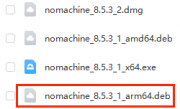
Then upload the downloaded nomachine_x.x.x_x_arm64.deb to the Linux system of the development board
Then use the following command to install NoMachine in the Linux system of the development board
orangepi@orangepi:~$ sudo dpkg -i nomachine_x.x.x_x_arm64_arm64.deb


- Then download the installation package of NoMachine software Windows version. The download address is as follows
Note that this download link may change.
https://downloads.nomachine.com/download/?id=9

Then install NoMachine in Windows. After installation, please restart your computer
Then open NoMachine in Windows

After NoMachine is started, it will automatically scan other devices with NoMachine installed in the LAN. After entering the main interface of NoMachine, you can see that the development board is already in the list of connectable devices. Then click the location indicated by the red box in the figure below to start logging into the Linux system desktop of the development board.

Then click OK

Then enter the user name and password of the development board Linux system in the corresponding position in the figure below, and then click OK to start logging in
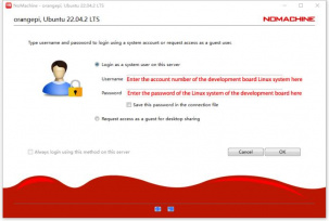
Then click OK in the following interface.
Finally, you can see the desktop of the development board Linux system
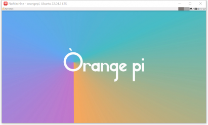


Remote login using VNC
Before operation, please make sure that the Windows computer and the development board are in the same LAN and can log in to the Ubuntu or Debian system of the development board normally through SSH.
There are many problems with testing VNC on Ubuntu 20.04, so please do not use this method.
首先First run the set_vnc.sh script to set up vnc, remember to add sudo permissions
orangepi@orangepi:~$ sudo set_vnc.sh
You will require a password to access your desktops.
Password: #Set the vnc password here, 8 characters
Verify: #Set the vnc password here, 8 characters
Would you like to enter a view-only password (y/n)? n
xauth: file /root/.Xauthority does not exist
New 'X' desktop is orangepi5ultra:1
Creating default startup script /root/.vnc/xstartup
Starting applications specified in /root/.vnc/xstartup
Log file is /root/.vnc/orangepi5ultra:1.log
Killing Xtightvnc process ID 3047
New 'X' desktop is orangepi5ultra:1
Starting applications specified in /root/.vnc/xstartup
Log file is /root/.vnc/orangepi5ultra:1.log
The steps to use MobaXterm software to connect to the Linux system desktop of the development board are as follows:
- First click Session, then select VNC, then fill in the IP address and port of the development board, and finally click OK to confirm

Then enter the VNC password set previously
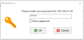
After successful login, the interface is displayed as shown below, and then you can remotely operate the desktop of the development board Linux system
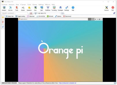


Test of some programming languages supported by Linux system
Debian Bullseye System
Debian Bullseye is installed with the gcc compilation tool chain by default, which can compile C language programs directly in the Linux system of the development board
The version of gcc is as follows
orangepi@orangepi:~$ gcc --version
gcc (Debian 10.2.1-6) 10.2.1 20210110
Copyright (C) 2020 Free Software Foundation, Inc.
This is free software; see the source for copying conditions. There is NO
warranty; not even for MERCHANTABILITY or FITNESS FOR A PARTICULAR PURPOSE.
Write the hello_world.c program in C language
orangepi@orangepi:~$ vim hello_world.c
#include <stdio.h>
int main(void)
{
printf("Hello World!\n");
return 0;
}
Then compile and run hello_world.c
orangepi@orangepi:~$ gcc -o hello_world hello_world.c
orangepi@orangepi:~$ ./hello_world
Hello World!
Debian Bullseye has Python3 installed by default
The specific version of Python is as follows
orangepi@orangepi:~$ python3
Python 3.9.2 (default, Feb 28 2021, 17:03:44)
[GCC 10.2.1 20210110] on linux
Type "help", "copyright", "credits" or "license" for more information.
>>>
Write the hello_world.py program in Python
orangepi@orangepi:~$ vim hello_world.py
print('Hello World!')
The result of running hello_world.py is as follows
orangepi@orangepi:~$ python3 hello_world.py
Hello World!
Debian Bullseye does not install Java compilation tools and runtime environment by default
You can use the following command to install openjdk. The latest version in Debian Bullseye is openjdk-17
orangepi@orangepi:~$ sudo apt install -y openjdk-17-jdk
After installation, you can check the Java version
orangepi@orangepi:~$ java --version
Write a Java version hello_world.java
orangepi@orangepi:~$ vim hello_world.java
public class hello_world
{
public static void main(String[] args)
{
System.out.println("Hello World!");
}
}
Then compile and run hello_world.java
orangepi@orangepi:~$ javac hello_world.java
orangepi@orangepi:~$ java hello_world
Hello World!
Debian Bookworm System
Debian Bookworm is installed with the gcc compilation toolchain by default, which can compile C language programs directly in the Linux system of the development board
gcc version is as follows
orangepi@orangepi:~$ gcc --version
gcc (Debian 12.2.0-14) 12.2.0
Copyright (C) 2022 Free Software Foundation, Inc.
This is free software; see the source for copying conditions. There is NO
warranty; not even for MERCHANTABILITY or FITNESS FOR A PARTICULAR PURPOSE.
Write the hello_world.c program in C language
orangepi@orangepi:~$ vim hello_world.c
#include <stdio.h>
int main(void)
{
printf("Hello World!\n");
return 0;
}
Then compile and run hello_world.c
orangepi@orangepi:~$ gcc -o hello_world hello_world.c
orangepi@orangepi:~$ ./hello_world
Hello World!
Debian Bookworm has Python 3 installed by default
The specific version of Python is as follows
orangepi@orangepi:~$ python3
Python 3.11.2 (main, Mar 13 2023, 12:18:29) [GCC 12.2.0] on linux
Type "help", "copyright", "credits" or "license" for more information.
>>>
Use the Ctrl+D shortcut key to exit Python's interactive mode.
Write the hello_world.py program in Python
orangepi@orangepi:~$ vim hello_world.py
print('Hello World!')
The result of running hello_world.py is as follows
orangepi@orangepi:~$ python3 hello_world.py
Hello World!
Debian Bookworm does not install Java compilation tools and runtime environment by default
You can use the following command to install openjdk. The latest version in Debian Bookworm is openjdk-17
orangepi@orangepi:~$ sudo apt install -y openjdk-17-jdk
After installation, you can check the Java version
orangepi@orangepi:~$ java --version
Write a Java version hello_world.java
orangepi@orangepi:~$ vim hello_world.java
public class hello_world
{
public static void main(String[] args)
{
System.out.println("Hello World!");
}
}
Then compile and run hello_world.java
orangepi@orangepi:~$ javac hello_world.java
orangepi@orangepi:~$ java hello_world
Hello World!
Ubuntu Focal system
Ubuntu Focal is installed with the gcc compilation tool chain by default, which can compile C language programs directly in the Linux system of the development board
gcc version is as follows
orangepi@orangepi:~$ gcc --version
gcc (Ubuntu 9.4.0-1ubuntu1~20.04.2) 9.4.0
Copyright (C) 2019 Free Software Foundation, Inc.
This is free software; see the source for copying conditions. There is NO
warranty; not even for MERCHANTABILITY or FITNESS FOR A PARTICULAR PURPOSE.
Write the hello_world.c program in C language
orangepi@orangepi:~$ vim hello_world.c
#include <stdio.h>
int main(void)
{
printf("Hello World!\n");
return 0;
}
Then compile and run hello_world.c
orangepi@orangepi:~$ gcc -o hello_world hello_world.c
orangepi@orangepi:~$ ./hello_world
Hello World!
Ubuntu Focal has Python 3 installed by default
The specific version of Python3 is as follows
orangepi@orangepi:~$ python3
Python 3.8.10 (default, Nov 14 2022, 12:59:47)
[GCC 9.4.0] on linux
Type "help", "copyright", "credits" or "license" for more information.
>>>
Write the hello_world.py program in Python
orangepi@orangepi:~$ vim hello_world.py
print('Hello World!')
The result of running hello_world.py is as follows
orangepi@orangepi:~$ python3 hello_world.py
Hello World!
Ubuntu Focal does not install Java compilation tools and runtime environment by default
You can use the following command to install openjdk-17
orangepi@orangepi:~$ sudo apt install -y openjdk-17-jdk
After installation, you can check the Java version
orangepi@orangepi:~$ java --version
openjdk 17.0.12 2024-07-16
OpenJDK Runtime Environment (build 17.0.12+7-Ubuntu-1ubuntu220.04)
OpenJDK 64-Bit Server VM (build 17.0.12+7-Ubuntu-1ubuntu220.04, mixed mode, sharing)
Write a Java version hello_world.java
orangepi@orangepi:~$ vim hello_world.java
public class hello_world
{
public static void main(String[] args)
{
System.out.println("Hello World!");
}
}
Then compile and run hello_world.java
orangepi@orangepi:~$ javac hello_world.java
orangepi@orangepi:~$ java hello_world
Hello World!
Ubuntu Jammy System
Ubuntu Jammy is installed with the gcc compilation tool chain by default, which can compile C language programs directly in the Linux system of the development board
gcc version is as follows
orangepi@orangepi:~$ gcc --version
gcc (Ubuntu 11.4.0-1ubuntu1~22.04) 11.4.0
Copyright (C) 2021 Free Software Foundation, Inc.
This is free software; see the source for copying conditions. There is NO
warranty; not even for MERCHANTABILITY or FITNESS FOR A PARTICULAR PURPOSE.
Write the hello_world.c program in C language
orangepi@orangepi:~$ vim hello_world.c
#include <stdio.h>
int main(void)
{
printf("Hello World!\n");
return 0;
}
Then compile and run hello_world.c
orangepi@orangepi:~$ gcc -o hello_world hello_world.c
orangepi@orangepi:~$ ./hello_world
Hello World!
Ubuntu Jammy has Python 3 installed by default
The specific version of Python3 is as follows
orangepi@orangepi:~$ python3
Python 3.10.12 (main, Jul 29 2024, 16:56:48) [GCC 11.4.0] on linux
Type "help", "copyright", "credits" or "license" for more information.
>>>
Write the hello_world.py program in Python
orangepi@orangepi:~$ vim hello_world.py
print('Hello World!')
The result of running hello_world.py is as follows
orangepi@orangepi:~$ python3 hello_world.py
Hello World!
Ubuntu Jammy does not install Java compilation tools and runtime environment by default
You can install openjdk-18 using the following command
orangepi@orangepi:~$ sudo apt install -y openjdk-18-jdk
After installation, you can check the Java version
orangepi@orangepi:~$ java --version
openjdk 18.0.2-ea 2022-07-19
OpenJDK Runtime Environment (build 18.0.2-ea+9-Ubuntu-222.04)
OpenJDK 64-Bit Server VM (build 18.0.2-ea+9-Ubuntu-222.04, mixed mode, sharing)
Write a Java version hello_world.java
orangepi@orangepi:~$ vim hello_world.java
public class hello_world
{
public static void main(String[] args)
{
System.out.println("Hello World!");
}
}
Then compile and run hello_world.java
orangepi@orangepi:~$ javac hello_world.java
orangepi@orangepi:~$ java hello_world
Hello World!
How to install QT
Use the following script to install QT5 and QT Creator
orangepi@orangepi:~$ install_qt.sh
After installation, the QT version number will be automatically printed
The Qt version that comes with Ubuntu 20.04 is 5.12.8
orangepi@orangepi:~$ install_qt.sh
......
QMake version 3.1
Using Qt version 5.12.8 in /usr/lib/aarch64-linux-gnu
The QT version that comes with Ubuntu 22.04 is 5.15.2
orangepi@orangepi:~$ install_qt.sh
......
QMake version 3.1
Using Qt version 5.15.2 in /usr/lib/aarch64-linux-gnu
The QT version that comes with Debian11 is 5.15.2
orangepi@orangepi:~$ install_qt.sh
......
QMake version 3.1
Using Qt version 5.15.2 in /usr/lib/aarch64-linux-gnu
The QT version that comes with Debian12 is 5.15.8
orangepi@orangepi:~$ install_qt.sh
......
QMake version 3.1
Using Qt version 5.15.8 in /usr/lib/aarch64-linux-gnu
Then you can see the QT Creator startup icon in Applications

You can also use the following command to open QT Creator
orangepi@orangepi:~$ qtcreator
During the startup of QT and QT applications, if the following error is prompted, please ignore it directly. This error will not affect the operation of the application.
libGL error: failed to create dri screen
libGL error: failed to load driver: rockchip
libGL error: failed to create dri screen
libGL error: failed to load driver: rockchip
The interface after QT Creator is opened is as follows
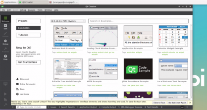
The version of QT Creator is as follows
The default version of QT Creator in Ubuntu 20.04 is as follows
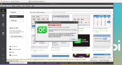
The default version of QT Creator in Ubuntu 22.04 is as follows

The default version of QT Creator in Debian 11 is as follows
The default version of QT Creator in Debian 12 is as follows
Then set up QT
First open Help->About Plugins...

Then remove the check mark of ClangCodeModel
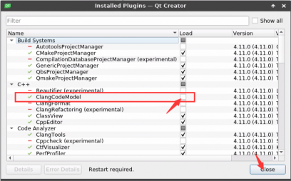
After setting, you need to restart QT Creator
Then make sure that QT Creator uses the GCC compiler. If it defaults to Clang, change it to GCC
For Debian 12, please skip this step.
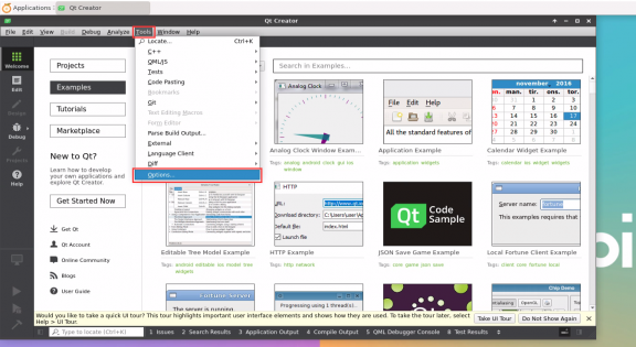
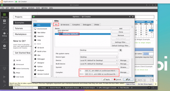
Then you can open a sample code
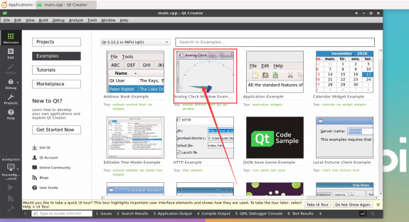
Clicking on the sample code will automatically open the corresponding documentation. Please read the instructions carefully
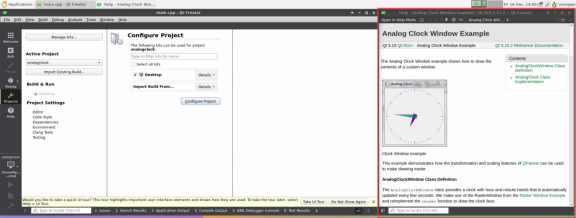
Then click Next Configure Project
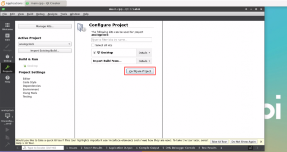
Then click the green triangle in the lower left corner to compile and run the sample code
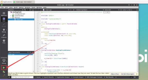
After waiting for a while, the interface shown in the figure below will pop up, which means that QT can compile and run normally
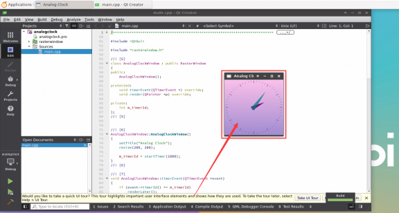
References
https://wiki.qt.io/Install_Qt_5_on_Ubuntu


ROS installation method
How to install ROS 1 Noetic on Ubuntu 20.04
- The currently active versions of ROS 1 are as follows, and the recommended versions are Noetic Ninjemys


https://wiki.ros.org/Distributions
The official installation document link for ROS 1 Noetic Ninjemys is as follows:
The official installation document of ROS Noetic Ninjemys recommends using Ubuntu 20.04, so make sure that the system used by the development board is the Ubuntu 20.04 desktop system
http://wiki.ros.org/noetic/Installation
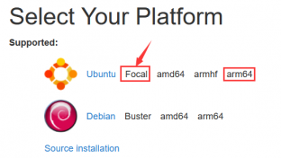
Then use the following script to install ros1
orangepi@orangepi5ultra:~$ install_ros.sh ros1
Before using the ROS tool, you first need to initialize rosdep, and then you can quickly install some system dependencies and some core components in ROS when compiling the source code.

Note that when running the following command, you need to ensure that the development board can access GitHub normally, otherwise an error will be reported due to network problems.
The install_ros.sh script will try to modify /etc/hosts and automatically run the following command. However, this method cannot guarantee that GitHub can be accessed normally every time. If the following error is prompted after install_ros.sh installs ros1, please find other ways to enable the Linux system of the development board to access GitHub normally, and then manually run the following command.
https://raw.githubusercontent.com/ros/rosdistro/master/rosdep/osx-homebrew.yaml
Hit https://raw.githubusercontent.com/ros/rosdistro/master/rosdep/base.yaml
ERROR: error loading sources list:
The read operation timed out
orangepi@orangepi:~$ source /opt/ros/noetic/setup.bash
orangepi@orangepi:~$ sudo rosdep init
Wrote /etc/ros/rosdep/sources.list.d/20-default.list
Recommended: please run
rosdep update
orangepi@orangepi:~$ rosdep update
reading in sources list data from /etc/ros/rosdep/sources.list.d
Hit https://raw.githubusercontent.com/ros/rosdistro/master/rosdep/osx-homebrew.yaml
Hit https://raw.githubusercontent.com/ros/rosdistro/master/rosdep/base.yaml
Hit https://raw.githubusercontent.com/ros/rosdistro/master/rosdep/python.yaml
Hit https://raw.githubusercontent.com/ros/rosdistro/master/rosdep/ruby.yaml
Hit https://raw.githubusercontent.com/ros/rosdistro/master/releases/fuerte.yaml
Query rosdistro index https://raw.githubusercontent.com/ros/rosdistro/master/index-v4.yaml
Skip end-of-life distro "ardent"
Skip end-of-life distro "bouncy"
Skip end-of-life distro "crystal"
Skip end-of-life distro "dashing"
Skip end-of-life distro "eloquent"
Add distro "foxy"
Add distro "galactic"
Skip end-of-life distro "groovy"
Add distro "humble"
Skip end-of-life distro "hydro"
Skip end-of-life distro "indigo"
Skip end-of-life distro "jade"
Skip end-of-life distro "kinetic"
Skip end-of-life distro "lunar"
Add distro "melodic"
Add distro "noetic"
Add distro "rolling"
updated cache in /home/orangepi/.ros/rosdep/sources.cache
Then open a command line terminal window on the desktop, and use the test_ros.sh script to start a small turtle routine to test whether ROS can be used normally
orangepi@orangepi:~$ test_ros.sh
After running the test_ros.sh script, a small turtle will pop up as shown in the figure below

Then please keep the terminal window you just opened on top


At this time, press the direction keys on the keyboard to control the turtle to move up, down, left and right.
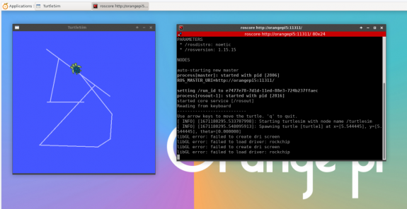

How to install ROS 2 Galactic on Ubuntu 20.04
The currently active versions of ROS 2 are as follows, and the recommended versions are Galactic Geochelone


The official installation document link of ROS 2 Galactic Geochelone is as follows:
docs.ros.org/en/galactic/Installation.html
http://docs.ros.org/en/galactic/Installation/Ubuntu-Install-Debians.html
The official installation document of ROS 2 Galactic Geochelone recommends using Ubuntu 20.04 for Ubuntu Linux, so make sure that the system used by the development board is the Ubuntu 20.04 desktop system. There are several ways to install ROS 2. The following demonstrates how to install ROS 2 Galactic Geochelone using Debian packages.
Use the install_ros.sh script to install ros2
orangepi@orangepi:~$ install_ros.sh ros2
After the install_ros.sh script installs ros2, it will automatically run the ros2 -h command. If you can see the following print, it means that ros2 installation is complete.
usage: ros2 [-h] Call `ros2 <command> -h` for more detailed usage. ...
ros2 is an extensible command-line tool for ROS 2.
optional arguments:
-h, --help show this help message and exit
Commands:
action Various action related sub-commands
bag Various rosbag related sub-commands
component Various component related sub-commands
daemon Various daemon related sub-commands
doctor Check ROS setup and other potential issues
interface Show information about ROS interfaces
launch Run a launch file
lifecycle Various lifecycle related sub-commands
multicast Various multicast related sub-commands
node Various node related sub-commands
param Various param related sub-commands
pkg Various package related sub-commands
run Run a package specific executable
security Various security related sub-commands
service Various service related sub-commands
topic Various topic related sub-commands
wtf Use `wtf` as alias to `doctor`
Call `ros2 <command> -h` for more detailed usage.
Then you can use the test_ros.sh script to test whether ROS 2 is installed successfully. If you can see the following print, it means that ROS 2 can run normally.
orangepi@orangepi5ultra:~$ test_ros.sh
[INFO] [1671174101.200091527] [talker]: Publishing: 'Hello World: 1'
[INFO] [1671174101.235661048] [listener]: I heard: [Hello World: 1]
[INFO] [1671174102.199572327] [talker]: Publishing: 'Hello World: 2'
[INFO] [1671174102.204196299] [listener]: I heard: [Hello World: 2]
[INFO] [1671174103.199580322] [talker]: Publishing: 'Hello World: 3'
[INFO] [1671174103.204019965] [listener]: I heard: [Hello World: 3]
Run the following command to open rviz2
orangepi@orangepi:~$ source /opt/ros/galactic/setup.bash
orangepi@orangepi:~$ ros2 run rviz2 rviz2
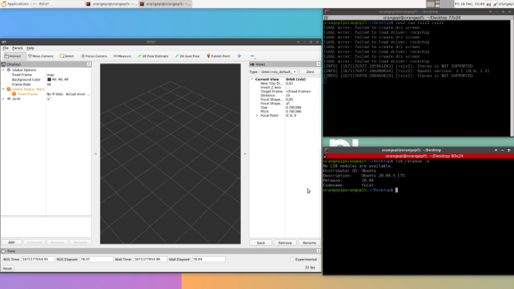
For the usage of ROS, please refer to the ROS 2 documentation


How to install ROS 2 Humble on Ubuntu 22.04
Use the install_ros.sh script to install ros2
orangepi@orangepi:~$ install_ros.sh ros2
After the install_ros.sh script installs ros2, it will automatically run the ros2 -h command. If you can see the following print, it means that ros2 installation is complete.
usage: ros2 [-h] Call `ros2 <command> -h` for more detailed usage. ...
ros2 is an extensible command-line tool for ROS 2.
optional arguments:
-h, --help show this help message and exit
Commands:
action Various action related sub-commands
bag Various rosbag related sub-commands
component Various component related sub-commands
daemon Various daemon related sub-commands
doctor Check ROS setup and other potential issues
interface Show information about ROS interfaces
launch Run a launch file
lifecycle Various lifecycle related sub-commands
multicast Various multicast related sub-commands
node Various node related sub-commands
param Various param related sub-commands
pkg Various package related sub-commands
run Run a package specific executable
security Various security related sub-commands
service Various service related sub-commands
topic Various topic related sub-commands
wtf Use `wtf` as alias to `doctor`
Call `ros2 <command> -h` for more detailed usage.
Then you can use the test_ros.sh script to test whether ROS 2 is installed successfully. If you can see the following print, it means that ROS 2 can run normally.
orangepi@orangepi5ultra:~$ test_ros.sh
[INFO] [1671174101.200091527] [talker]: Publishing: 'Hello World: 1'
[INFO] [1671174101.235661048] [listener]: I heard: [Hello World: 1]
[INFO] [1671174102.199572327] [talker]: Publishing: 'Hello World: 2'
[INFO] [1671174102.204196299] [listener]: I heard: [Hello World: 2]
[INFO] [1671174103.199580322] [talker]: Publishing: 'Hello World: 3'
[INFO] [1671174103.204019965] [listener]: I heard: [Hello World: 3]
Run the following command to open rviz2
orangepi@orangepi:~$ source /opt/ros/humble/setup.bash
orangepi@orangepi:~$ ros2 run rviz2 rviz2
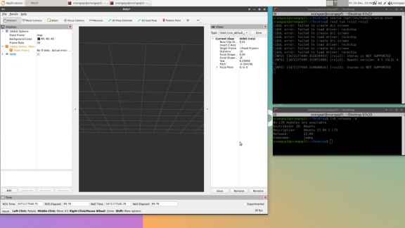
Reference Documents
http://docs.ros.org/en/humble/index.html
http://docs.ros.org/en/humble/Installation/Ubuntu-Install-Debians.html

How to install kernel header files
The Linux image released by OPi comes with a deb package of kernel header files by default, which is stored in /opt/
The names of the deb packages of kernel header files of different kernel versions may be different. Please refer to the actual ones you see.
orangepi@orangepi:~$ ls /opt/linux-headers*
/opt/linux-headers-legacy-rockchip-rk3588_x.x.x_arm64.deb
Use the following command to install the kernel header file deb package
The name of the kernel header file deb package needs to be replaced with the actual name, please do not copy it.
orangepi@orangepi:~$ sudo dpkg -i /opt/linux-headers-legacy-rockchip-rk3588_1.x.x_arm64.deb
After installation, you can see the folder where the kernel header files are located under /usr/src
orangepi@orangepi:~$ ls /usr/src
linux-headers-5.10.160-rockchip-rk3588
Then you can write a hello kernel module to test the kernel header file
First, write the code for the hello kernel module as follows:
orangepi@orangepi:~$ vim hello.c
#include <linux/init.h>
#include <linux/module.h>
static int hello_init(void)
{
printk("Hello Orange Pi -- init\n");
return 0;
}
static void hello_exit(void)
{
printk("Hello Orange Pi -- exit\n");
return;
}
module_init(hello_init);
module_exit(hello_exit);
MODULE_LICENSE("GPL");
Then write the Makefile file to compile the hello kernel module as follows:
orangepi@orangepi:~$ vim Makefile
ifneq ($(KERNELRELEASE),)
obj-m:=hello.o
else
KDIR :=/lib/modules/$(shell uname -r)/build
PWD :=$(shell pwd)
all:
make -C $(KDIR) M=$(PWD) modules
clean:
rm -f *.ko *.o *.mod.o *.mod *.symvers *.cmd *.mod.c *.order
endif
Then use the make command to compile the hello kernel module. The output of the compilation process is as follows:
If there is a problem compiling the copied code here, you can directly use the source code pre-installed in the Linux system. The path of the hello source code is: /usr/src/hello.
orangepi@orangepi:~$ sudo make
make -C /lib/modules/5.10.160-rockchip-rk3588/build M=/home/orangepi modules
make[1]: Entering directory '/usr/src/linux-headers-5.10.160-rockchip-rk3588'
CC [M] /home/orangepi/hello.o
MODPOST /home/orangepi/Module.symvers
CC [M] /home/orangepi/hello.mod.o
LD [M] /home/orangepi/hello.ko
make[1]: Leaving directory '/usr/src/linux-headers-5.10.160-rockchip-rk3588'
After compilation, the hello.ko kernel module will be generated
orangepi@orangepi:~$ ls *.ko
hello.ko
Use the insmod command to insert the hello.ko kernel module into the kernel
orangepi@orangepi:~$ sudo insmod hello.ko
Then use the demsg command to view the output of the hello.ko kernel module. If you can see the following output, it means that the hello.ko kernel module is loaded correctly.
orangepi@orangepi:~$ dmesg | grep "Hello"
[ 2871.893988] Hello Orange Pi -- init
Use the rmmod command to uninstall the hello.ko kernel module
orangepi@orangepi:~$ sudo rmmod hello
orangepi@orangepi:~$ dmesg | grep "Hello"
[ 2871.893988] Hello Orange Pi -- init
[ 3173.800892] Hello Orange Pi -- exit
How to use 10.1 inch MIPI LCD screen
10.1 inch MIPI screen assembly method
First prepare the necessary accessories
10.1 inch MIPI LCD display + touch screen

Screen adapter board + 31pin to 40pin cable

30pin MIPI cable

12pin touch screen cable

Connect the 12-pin touch screen cable, 31-pin to 40-pin cable, and 30-pin MIPI cable to the screen adapter board as shown below. Note that the blue insulation side of the touch screen cable should face downward, and the insulation sides of the other two cables should face upward. If connected incorrectly, it will cause no display or inability to touch.

Place the adapter board with the connected cable on the MIPI LCD screen as shown below, and connect the MIPI LCD screen and the adapter board via a 31pin to 40pin cable.


Then connect the touch screen and the adapter board through the 12-pin touch screen cable, paying attention to the direction of the insulating surface

Finally, connect it to the LCD interface of the development board through the 30pin MIPI cable
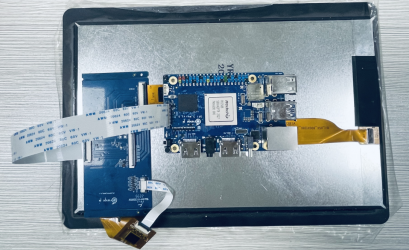


How to open the 10.1-inch MIPI LCD screen configuration
- The Linux image does not have the mipi lcd screen configuration turned on by default. If you need to use the mipi lcd screen, you need to turn it on manually.
- The location of the interface of the mipi lcd screen on the development board is shown in the figure below:

The steps to open the mipi lcd configuration are as follows:
First run orangepi-config. Ordinary users should remember to add sudo permissions.
orangepi@orangepi:~$ sudo orangepi-config
Then select System

Then select Hardware
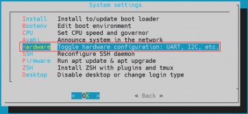
Then use the arrow keys on the keyboard to locate opi5ultra-lcd, and then use the spacebar to select

Then select <Save> to save
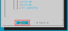
Then select <Back>
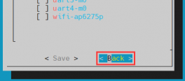
Then select <Reboot> to restart the system for the configuration to take effect
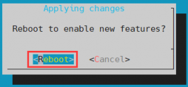
The above settings will eventually add overlays=opi5ultra-lcd to /boot/orangepiEnv.txt. You can check it after setting it. If this line does not exist, then there is a problem with the settings.
If you find it troublesome to use orangepi-config, you can also use the vim editor to open /boot/orangepiEnv.txt and add the line overlays=opi5ultra-lcd.
orangepi@orangepi:~$ cat /boot/orangepiEnv.txt | grep "lcd"
overlays=opi5ultra-lcd #Example Configuration
After startup, you can see the LCD screen display as follows (the default is vertical):


How to rotate the display direction of the server version image
Add extraargs=fbcon=rotate: direction to be rotated in /boot/orangepiEnv.txt to set the display direction of the server version of Linux system. The number after fbcon=rotate: can be set to:
0: Normal screen (portrait by default)
1: Rotate 90 degrees clockwise
2: Flip 180 degrees
3: Rotate 270 degrees clockwise
orangepi@orangepi:~$ sudo vim /boot/orangepiEnv.txt
extraargs=cma=128M fbcon=rotate:3
overlays=opi5ultra-disable-leds
Note that if there is a line of extraargs=cma=128M in /boot/orangepiEnv.txt by default, you can add the line fbcon=rotate:3 after extraargs=cma=128M (separated by a space).
Then restart the Linux system and you will see that the direction of the LCD screen display has rotated
Desktop version mirroring rotation display and touch direction method
First open the Display settings in the Linux system

Then select the direction you want to rotate in Rotation
None: No rotation
Left: Rotate 90 degrees left
Inverted: Flip upside down, equivalent to rotating 180 degrees
Right: Rotate right 90 degrees
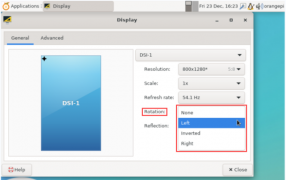
Then click Apply
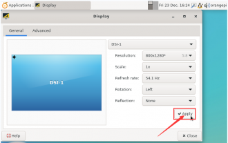
Then select Keep this configuration
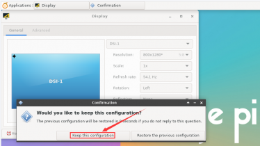
The screen display has been rotated, and you can close the Display program
The above steps will only select the display direction, but will not rotate the touch direction. You can use the set_lcd_rotate.sh script to rotate the touch direction. After setting this script, it will automatically restart, and then you can test whether the touch can be used normally.
None: No rotation
orangepi@orangepi:~$ set_lcd_rotate.sh none
Left: Rotate 90 degrees left
orangepi@orangepi:~$ set_lcd_rotate.sh left
Inverted: Flip upside down, equivalent to rotating 180 degrees
orangepi@orangepi:~$ set_lcd_rotate.sh inverted
Right: Rotate right 90 degrees
orangepi@orangepi:~$ set_lcd_rotate.sh right
The set_lcd_rotate.sh script does four main things:


Rotate the direction of the framebuffer display
Rotate the touch direction
Turn off the startup logo
Restart the system
Rotating the touch direction is achieved by adding Option "TransformationMatrix" "x x x x x x x x x x" to /usr/share/X11/xorg.conf.d/40-libinput.conf, where "x x x x x x x x x x" has different configurations for different directions.
Touch to rotate the reference
Instructions for using the power on/off logo
The power on/off logo is only displayed in the desktop version of the system by default.
Set the bootlogo variable to false in /boot/orangepiEnv.txt to turn off the power on/off logo
orangepi@orangepi:~$ vim /boot/orangepiEnv.txt
verbosity=1
bootlogo=false
Set the bootlogo variable to true in /boot/orangepiEnv.txt to enable the power on/off logo
orangepi@orangepi:~$ vim /boot/orangepiEnv.txt
verbosity=1
bootlogo=true
The location of the boot logo image in the Linux system is
/usr/share/plymouth/themes/orangepi/watermark.png
After replacing the boot logo image, you need to run the following command to take effect
orangepi@orangepi:~$ sudo update-initramfs -u
Test Methods for OV13850 and OV13855 MIPI Cameras
Please note that in Linux systems, in order to ensure that the 3A service can run normally and obtain normal camera images, the Docker service needs to be disabled. If the Docker service is not disabled, the image captured by the camera will not contain the 3A effect and will appear as a dark image. The method to disable the Docker service is as follows:
orangepi@orangepi:~$ sudo systemctl disable docker.socket docker.service containerd.service
orangepi@orangepi:~$ sudo reboot
Currently the development board supports two MIPI cameras, OV13850 and OV13855. The specific pictures are as follows:
13MP OV13850 camera with MIPI interface

13MP OV13855 camera with MIPI interface

The adapter board and FPC cable used by OV13850 and OV13855 cameras are the same, but the two cameras are connected to the adapter board in different positions. The FPC cable is shown in the figure below. Please note that the FPC cable has a direction. The end marked with TO MB needs to be plugged into the camera interface of the development board, and the end marked with TO CAMERA needs to be plugged into the camera adapter board.

There are a total of 3 camera interfaces on the camera adapter board. Only one can be connected at a time, as shown in the following figure:
Interface 1 is connected to the OV13850 camera
Interface 2 is connected to the OV13855 camera
Interface 3 is not used, just ignore it

There are three camera interfaces on the Orange Pi 5 Ultra development board. We define the positions of Cam0, Cam1, and Cam2 as shown in the following figure:


The method of inserting the camera into the Cam0 interface of the development board is as follows:

The method of inserting the camera into the Cam1 interface of the development board is as follows:

The method of inserting the camera into the Cam2 interface of the development board is as follows:

After connecting the camera to the development board, we can use the following method to test the camera:
First run orangepi-config. Ordinary users should remember to add sudo permissions.
orangepi@orangepi:~$ sudo orangepi-config
Then select System

Then select Hardware

Then use the arrow keys on the keyboard to locate the position shown in the figure below, and then use the space bar to select the camera you want to open. opi5ultra-cam0 means using the ov13850 or ov13855 camera in the Cam0 interface of the development board, opi5ultra-cam1 means using the ov13850 or ov13855 camera in the Cam1 interface of the development board, and opi5ultra-cam2 means using the ov13850 or ov13855 camera in the Cam2 interface of the development board.

Then select <Save> to save
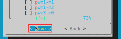
Then select <Back>

Then select <Reboot> to restart the system for the configuration to take effect

Then open a terminal in the desktop system and run the following script
orangepi@orangepi:~$ test_camera.sh
Then you can see the camera preview
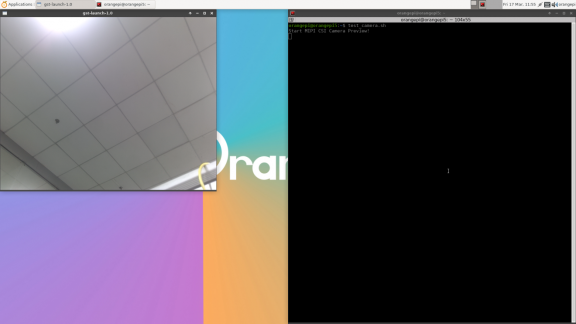
In addition to a single camera, we can also use two or three cameras at the same time (supporting ov13850 and ov13855 mixed). After connecting the three cameras, open the configuration of Cam0+Cam1+Cam2 through orangepi-config as in the previous steps, restart the system, and then open the terminal on the desktop to run the test_camera.sh script to see the preview of the three cameras, as shown in the figure below:
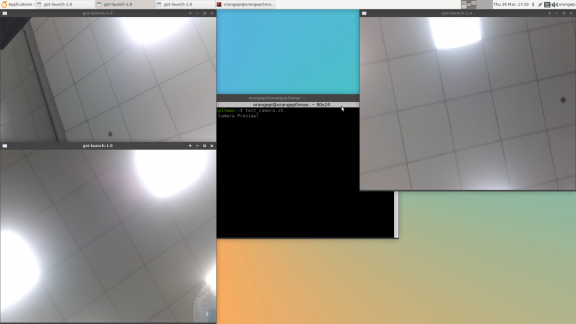


How to use ZFS file system
How to install ZFS
Before installing zfs, please make sure that the Linux image you are using is the latest version. In addition, if zfs has already been installed on the system, there is no need to install it again.
Before installing zfs, you need to install the kernel header file first. For the method of installing the kernel header file, please refer to the instructions in the section "How to install the kernel header file".
In Ubuntu 20.04, Ubuntu 22.04 and Debian 11 systems, zfs cannot be installed directly through apt. This is because the zfs version in the default apt source is lower than 2.1.6, which is incompatible with the rk linux 5.10 kernel. This problem has been fixed in zfs 2.1.6 and later versions.
To solve this problem, we provide a deb package of zfs that can be installed normally, which can be downloaded from the official tool of the development board. Open the official tool and enter the deb package folder related to zfs used by Ubuntu and Debian systems. You can see three types of deb packages: Ubuntu20.04, Ubuntu22.04 and Debian11. Please download the required version.

After downloading the corresponding version of zfs deb package, please upload them to the Linux system of the development board. For the upload method, please refer to the instructions in the section "How to upload files to the Linux system of the development board".
After uploading, use the cd command in the command line of the Linux system of the development board to enter the directory of the deb package, and then use the following command to install the zfs deb package.
orangepi@orangepi:~$ sudo apt -y install ./*.deb
Then restart the Linux system and you will see that the zfs kernel module will be automatically loaded:
orangepi@orangepi:~$ lsmod | grep "zfs"
zfs 2801664 0
zunicode 327680 1 zfs
zzstd 471040 1 zfs
zlua 139264 1 zfs
zcommon 69632 1 zfs
znvpair 61440 2 zfs,zcommon
zavl 16384 1 zfs
icp 221184 1 zfs
spl 77824 6 zfs,icp,zzstd,znvpair,zcommon,zavl
In Debian 12, the default version of zfs is 2.1.11, so we can install zfs directly through the following command. Once again, please make sure that the system has installed the deb package of the kernel header file before installation.
orangepi@orangepi:~$ sudo apt install -y zfsutils-linux zfs-dkms
How to create a ZFS pool
ZFS is based on storage pools. We can add multiple physical storage devices to a pool and then allocate storage space from this pool.
The following content is demonstrated based on the development board connected to an NVMe SSD and a USB flash drive.
First, we can use the lsblk command to view all storage devices on the development board. The current development board is connected to an NVMe SSD and a USB flash drive. The output is as follows:
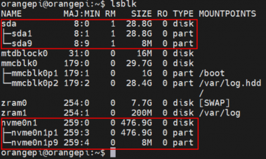
Then enter the following command to create a ZFS pool containing two storage devices: NVMe SSD and USB flash drive
orangepi@orangepi:~$ sudo zpool create -f pool1 /dev/nvme0n1 /dev/sda
Then use the zpool list command to see that the system has created a ZFS pool named pool1, and the size of the ZFS pool pool1 is the size of the NVME SSD plus the size of the USB flash drive.

Then execute df -h to see that pool1 is mounted to the /pool1 directory
orangepi@orangepi:~$ df -h
Filesystem Size Used Avail Use% Mounted on
tmpfs 1.6G 18M 1.6G 2% /run
/dev/mmcblk0p2 29G 6.0G 22G 22% /
tmpfs 7.7G 46M 7.7G 1% /dev/shm
tmpfs 5.0M 4.0K 5.0M 1% /run/lock
tmpfs 7.7G 944K 7.7G 1% /tmp
/dev/mmcblk0p1 1022M 115M 908M 12% /boot
/dev/zram1 188M 4.5M 169M 3% /var/log
tmpfs 1.6G 80K 1.6G 1% /run/user/1000
pool1 489G 9.3M 489G 1% /pool1
Use the following command to see that the file system type of pool1 is zfs
orangepi@orangepi:~$ mount | grep pool1
pool1 on /pool1 type zfs (rw,xattr,noacl)
Then we can test copying a file to the ZFS pool
orangepi@orangepi:~$ sudo cp -v /usr/local/test.mp4 /pool1/
'/usr/local/test.mp4' -> '/pool1/test.mp4'

Test ZFS data deduplication function
ZFS data deduplication function is disabled by default. We need to execute the following command to enable it.
orangepi@orangepi:~$ sudo zfs set dedup=on pool1
Then do a simple test. First enter pool1 and then execute the following command to generate a random file of 1G size:
orangepi@orangepi:~$ cd /pool1/
root@orangepi:/pool1$ sudo dd if=/dev/urandom of=test.1g bs=1M count=1024
1024+0 records in
1024+0 records out
1073741824 bytes (1.1 GB, 1.0 GiB) copied, 5.04367 s, 213 MB/s
Then use the following command to copy 1000 copies of a random file of size 1G
root@orangepi:/pool1$ for ((i=0; i<1000; i++)); do sudo cp test.1g $i.test.1g; done
- Then use du -lh to see that there is a total of 1002G of data in the pool. However, the actual size of the ZFS pool is only 504GB (the total capacity of the SSD + USB drive), which is too large to accommodate such a large amount of data.
root@orangepi:/pool1$ du -lh
1002G
Then use the zpool list command to see that only 1.01G is actually occupied. Because these 1001 files are duplicated, the data deduplication function is effective.

Test ZFS data compression function
- Because the stored data is different, the disk space saved by compression will also be different, so we choose to compress relatively large plain text files for compression testing. Execute the following command to package the /var/log/ and /etc/ directories into a tar package
orangepi@orangepi:~$ cd /pool1/
root@orangepi:/pool1$ sudo tar -cf text.tar /var/log/ /etc/
Then, the file size and the space occupied in the ZFS pool can be seen by the ls -lh command, both of which are 27M.
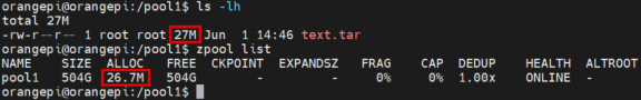
Then we enable compression in ZFS pool pool1
root@orangepi:/pool1$ sudo zfs set compression=lz4 pool1
Then execute the following command again to package the /var/log/ and /etc/ directories into a tarball

root@orangepi:/pool1$ sudo tar -cf text.tar /var/log/ /etc/
- Then you can see that the file size of text.tar is still 27M, but it only takes up 9.47M of space in the ZFS pool, indicating that the file has been compressed.

How to install and use CasaOS
CasaOS is an open source home cloud system based on the Docker ecosystem, which allows you to run a variety of home applications on your own development board, such as NAS, home automation, media server, etc.
How to install CasaOS
First, you need to install docker. The system released by Orangepi Pi has docker pre-installed. This step can be skipped. You can use the following command to view the installed docker version
orangepi@orangepi:~$ docker --version
Then enter the following command in the Linux system to start the installation of CasaOS
orangepi@orangepi:~$ curl -fsSL https://get.casaos.io | sudo bash
When you see the following print information output in the terminal, it means that CasaOS has been installed.
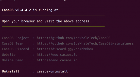

How to use CasaOS
After installing CasaOS, enter http://development board IP address in the browser to open CasaOS
After opening CasaOS, the following welcome interface will pop up. Click "Go" to proceed to the next step
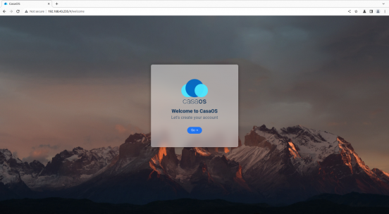
When you log in to CasaOS for the first time, the login interface is the interface for setting the account and password. When you log in again, only the interface for entering the account and password will appear. After setting the account and password, click "Create" to proceed to the next step.

In the following interface, click "Accept" to proceed to the next step
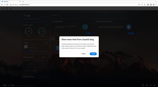
Now you have entered the main page of CasaOS. There are three icons in the upper left corner for function settings. The left side is the performance panel, which can display the current time and the status information of CPU, RAM, storage, and network. The right side is the function panel, which has functions such as search, application recommendation, application store, and file management.

Click the first icon in the upper left corner to modify your account and password
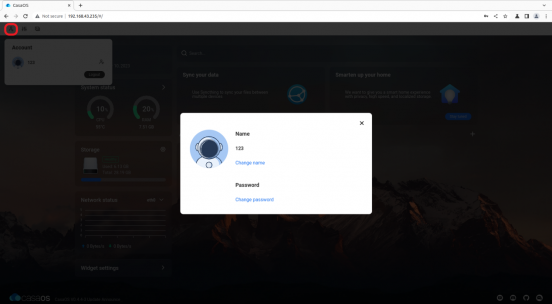
Click the second icon to set basic functions
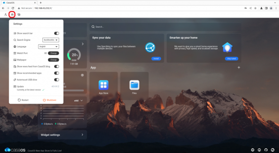
The third icon in the upper left corner has two main functions, namely switching to command line mode and printing log information. When switching to command line mode, you need to enter the account and password. The account and password here refer to the account and password of the development board Linux system. The default port system selects 22.
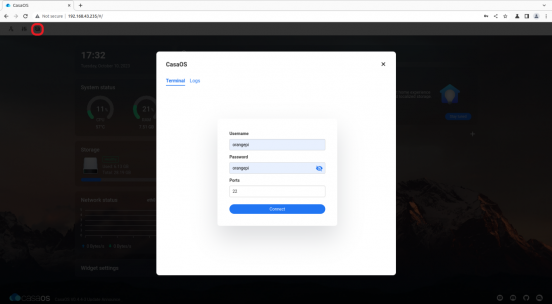
Then click "Connect" to enter the command line interface:
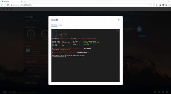
Another function under the third icon is to print the CasaOS log. Click "Logs" to enter. The interface is as follows:
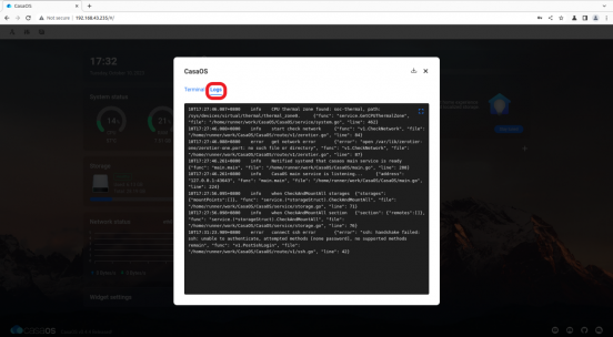
Click "Widget settings" in the lower left corner to set whether to display the performance panel widget on the main page

Click "APP Store" on the main interface to open the App Store. Currently, there are more than 70 APPs available in the App Store.
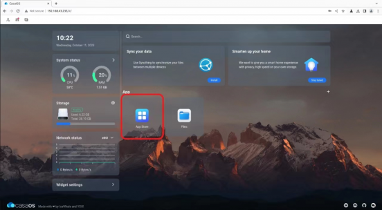
Here we take Home Assistant as an example to download. Find Home Assistant in the APP Store and click the corresponding "install"

After the download is complete, HostAssitant will appear on the main page
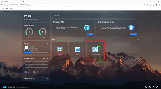
Click "Files" in the main interface to open the file system that comes with CasaOS, and then you can upload and save files
Please make sure other devices and the development board are in the same LAN.
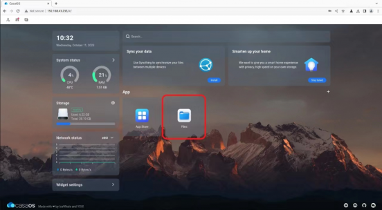
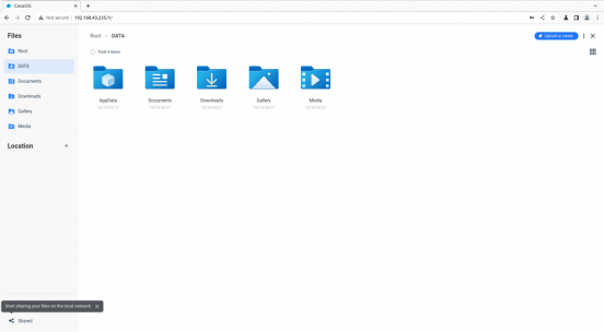
When uploading files, you need to switch to the target folder, then drag the local file to the indicated area in the figure, or click "Upload or Create" in the upper right corner to select the file to upload.
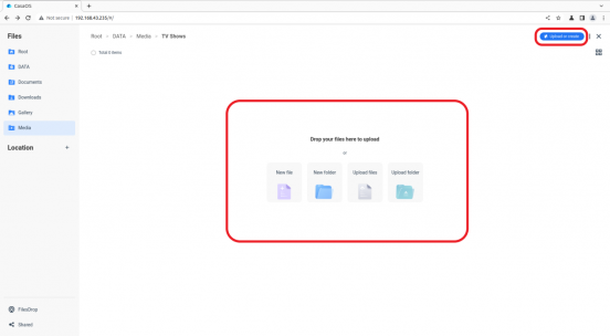
If you want to uninstall CasaOS, you can use the following command:
orangepi@orangepi:~$ sudo casaos-uninstall


Methods of using NPU
Prepare tools
- A PC with Ubuntu 20.04 operating system
According to the official documentation of RKNN-Toolkit2, the operating systems supported by the current version of RKNN-Toolkit2 are as follows:
a. Ubuntu18.04 (x64)
b. Ubuntu20.04 (x64)
c. Ubuntu22.04 (x64)
In this document, we use the Ubuntu 20.04 (x64) operating system for demonstration. Please test other versions of the operating system yourself.
An RK3588 development board with Debian 11 installed
Prepare a good quality USB2.0 male-to-male data cable for using the adb function

Install RKNN-Toolkit2 on Ubuntu PC
Toolkit2 is a development kit used on the Ubuntu PC platform. Users can use the Python interface provided by the tool to easily complete functions such as model conversion, reasoning, and performance evaluation.
On the Ubuntu PC, open a command line window and enter the following commands to install python3 and pip3
test@test:~$ sudo apt-get install -y python3 python3-dev python3-pip
You can use the following command to view the installed version of python3
test@test:~$ python3 --version
Python 3.8.10
Then enter the following command to install the dependency package of RKNN-Toolkit2
test@test:~$ sudo apt-get update
test@test:~$ sudo apt-get -y install libxslt1-dev zlib1g-dev libglib2.0 \
libsm6 libgl1-mesa-glx libprotobuf-dev gcc
Then enter the following command to download the 1.5.2 version of RKNN-Toolkit2
test@test:~$ git clone https://github.com/airockchip/rknn-toolkit2 -b v1.5.2
Then enter the following command to install the corresponding version of Python3 dependency packages. This command will use pip3 to install the dependencies listed in the file requirements_cp38-1.5.2.txt. If the dependencies are not fully installed, do not specify the installation source and install each package separately.
test@test:~$ pip3 install -r rknn-toolkit2/doc/requirements_cp38-1.5.2.txt -i https://mirror.baidu.com/pypi/simple
Then enter the following command to use pip3 to install the RKNN-Toolkit2 software package. After the installation is complete, you can use RKNN-Toolkit2
test@test:~$ pip3 install -r rknn-toolkit2/doc/requirements_cp38-1.5.2.txt -i https://pypi.tuna.tsinghua.edu.cn/simple
Model conversion and model inference using RKNN-Toolkit2
RKNN-Toolkit2 supports converting Caffe, TensorFlow, TensorFlow Lite, ONNX, DarkNet, PyTorch and other models into RKNN models, and then running the RKNN model on the Ubuntu PC through simulation or using the NPU of the development board for inference.
Relevant examples are provided in the example folder of RKNN-Toolkit2 to help users better understand how to operate. We take the ONNX model with yolov5 function as an example.
Simulate the model on Ubuntu PC
RKNN-Toolkit2 is equipped with a built-in simulator, which allows users to simulate the inference process of the model on Rockchip NPU on Ubuntu PC.
In this way, model conversion and inference can be completed on the Ubuntu PC, helping users test and verify their models faster.
- First switch to the rknn-toolkit2/examples/onnx/yolov5 directory
test@test:~$ cd rknn-toolkit2/examples/onnx/yolov5/
- Then run the test.py script, which first converts the yolov5s_relu.onnx model into an RKNN model that can be run on the simulator, and then uses the simulator to simulate and run the model to perform inference on the bus.jpg image in the current directory.
test@test:~/rknn-toolkit2/examples/onnx/yolov5$ python3 test.py
- After the test.py script runs successfully, you will see the following print information, indicating that the model successfully detected four people and a bus in the bus.jpg image
done
--> Running model
W inference: The 'data_format' has not been set and defaults is nhwc!
done
class: person, score: 0.884139358997345
box coordinate left,top,right,down: [209.1040009856224, 244.4304337501526, 286.5742521882057, 506.7466902732849]
class: person, score: 0.8676778078079224
box coordinate left,top,right,down: [478.5757632255554, 238.58572268486023, 559.5273861885071, 526.479279756546]
class: person, score: 0.8246847987174988
box coordinate left,top,right,down: [110.57257843017578, 238.58099019527435, 230.54625701904297, 534.0008579492569]
class: person, score: 0.3392542004585266
box coordinate left,top,right,down: [79.96397459506989, 354.9062474966049, 122.13020265102386, 516.2529321908951]
class: bus , score: 0.7012234926223755
box coordinate left,top,right,down: [94.43931484222412, 129.53470361232758, 553.1492471694946, 468.0852304697037]
D NPUTransfer: Transfer client closed, fd = 3
The converted model file yolov5s_relu.rknn and the inference picture result result.jpg are saved in the current directory
The result.jpg image shows the object categories and confidence rates detected in the bus.jpg image using the yolov5s_relu.rknn model


Using the NPU of the development board to run the model on Ubuntu PC
RKNN-Toolkit2 provides users with a Python interface for using the development board's NPU for reasoning through adb, allowing users to use the development board's NPU to run models for reasoning on an Ubuntu PC.
In this way, the Ubuntu PC can use the machine learning library provided by Python to optimize and adjust the model according to the actual effect of the model running on the NPU of the development board.
Connect adb using a USB male-to-male data cable
Use adb to operate the development board on the Ubuntu PC. For the usage of adb, please refer to the instructions in the section How to use ADB.
Update the rknn_derver and librknnrt.so of the development board
librknnrt.so is a board-side runtime library.
rknn_server is a background proxy service running on the development board. It is used to receive the protocol transmitted from the PC via USB, then execute the corresponding interface in the board runtime library and return the result to the PC.
First, enter the following command on the Ubuntu PC to download the 1.5.2 version of RKNPU2
test@test:~$ git clone https://github.com/rockchip-linux/rknpu2 -b v1.5.2
Then enter the following command on the Ubuntu PC to update the rknn_server of the development board through the adb tool
test@test:~$ adb push rknpu2/runtime/RK3588/Linux/rknn_server/aarch64/usr/bin/* /usr/bin
Then enter the following command on the Ubuntu PC to update the librknnrt.so library of the development board through the adb tool
test@test:~$ adb push rknpu2/runtime/RK3588/Linux/librknn_api/aarch64/librknnrt.so /usr/lib
Open the terminal of the development board through the adb tool
test@test:~$ adb shell
Open the rknn_server service of the development board
root@orangepi:/# sudo restart_rknn.sh
root@orangepi:/# start rknn server,version:1.5.2(8babfeabuild@2023-08-25T10:30:31)
I NPUTransfer: Starting NPU TransferServer,Transfer version 2.1.0(b5861e7@2020-11-23T11:50:51)
Using the following command to check. If the process ID of rknn_server appears, it means that rknn_server has been opened, and the operating environment of the development board has been set up.
root@orangepi:/# pgrep rknn_server
3131
Modify the parameters in the example
On the Ubuntu PC, you can use the following command to view the device ID of the development board connected to the Ubuntu PC. This ID will be used below.
test@test:~$ adb devices
List of devices attached
4f9f859e5a120324 device
Switch to the rknn-toolkit2/examples/onnx/yolov5 directory
test@test:~$ cd rknn-toolkit2/examples/onnx/yolov5/
- Use the vim editor to modify the test.py file
test@test:~/rknn-toolkit2/examples/onnx/yolov5$ vim test.py
In the test.py file, we need to modify the following content:
- In the preprocessing configuration, change the target platform to rk3588, so that the model conversion results in an RKNN model suitable for the NPU of the RK3588 development board.

- In the initialization running environment, add the description of the target platform and device ID. The target platform is rk3588, and the device ID is the device ID of the development board obtained through adb. The operation of running the model for inference will be performed on the NPU of the RK3588 development board.

- After the modification is completed, save and exit
Run the example on Ubuntu PC
- Enter the following command to run the test.py script. The script first converts the yolov5s_relu.onnx model to the RKNN model, and then loads the model to the NPU of the development board to perform inference on the out.jpg image in the current directory.
test@test:~/rknn-toolkit2/examples/onnx/yolov5$ python3 test.py
- In the printed information, we can see that the Ubuntu PC uses the NPU of the development board to run the model for inference through the adb tool
--> Init runtime environment
I target set by user is: rk3588
I Check RK3588 board npu runtime version
I Starting ntp or adb, target is RK3588
I Device [4f9f859e5a120324] not found in ntb device list.
I Start adb...
I Connect to Device success!
I NPUTransfer: Starting NPU Transfer Client, Transfer version 2.1.0 (b5861e7@2020-11-23T11:50:36)
After the test.py script runs successfully, the converted model file yolov5s_relu.rknn and the inference image result result.jpg are saved in the current directory
The results of the operation are the same as those in the section Simulating the model on the Ubuntu PC.
Call the C interface to deploy the RKNN model to the development board to run
RKNPU2 provides a C programming interface for chip platforms with Rockchip NPU, which can help users deploy RKNN models exported using RKNN-Toolkit2 and accelerate the implementation of AI applications.
In the example folder of RKNPU2, examples of deploying RKNN models with different functions to the development board are provided. We take the deployment of the RKNN model with yolov5 function to the RK3588 Debian11 platform as an example.
Download cross-compilation tools
Since the development board runs on Linux, you need to use the gcc cross compiler to compile. It is recommended to use the gcc version gcc-9.3.0-x86_64_arrch64-linux-gnu.
Enter the following command to download this version of gcc. After downloading, you will get a folder named gcc-buildroot-9.3.0-2020.03-x86_64_aarch64-rockchip-linux-gnu.
test@test:~$ git clone https://github.com/airockchip/gcc-buildroot-9.3.0-2020.03-x86_64_aarch64-rockchip-linux-gnu
Modify the compiler tool path in the script
Switch to the rknpu2/examples/rknn_yolov5_demo directory
test@test:~$ cd ~/rknpu2/examples/rknn_yolov5_demo
Use the vim editor to modify the contents of the build-linux_RK3588.sh file.
test@test:~/rknpu2/examples/rknn_yolov5_demo$ vim build-linux_RK3588.sh
In the build-linux_RK3588.sh file, we need to change the value of the variable TOOL_CHAIN to the path of the gcc-buildroot-9.3.0-2020.03-x86_64_aarch64-rockchip-linux-gnu folder. In this way, when running the build-android_RK3588.sh script, the cross-compilation tool in the gcc-buildroot-9.3.0-2020.03-x86_64_aarch64-rockchip-linux-gnu folder will be used for compilation.
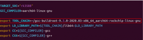
After the modification is completed, save and exit.

Compile rknn_yolov5_demo
Run build-linux_RK3588.sh, which generates a program suitable for the RK3588 development board through cross-compilation and can run the RKNN model for inference on it
test@test:~/rknpu2/examples/rknn_yolov5_demo$ sudo apt install cmake
test@test:~/rknpu2/examples/rknn_yolov5_demo$ sudo apt-get install g++-aarch64-linux-gnu
test@test:~/rknpu2/examples/rknn_yolov5_demo$ ./build-linux_RK3588.sh
After running build-linux_RK3588.sh, there will be an additional folder named install in the current directory. The rknn_yoov5_demo_Linux folder under this folder contains the program generated by cross-compilation and its related files
test@test:~/rknpu2/examples/rknn_yolov5_demo$ ls install
rknn_yolov5_demo_Linux
Deploy rknn_yolov5_demo to the development board
On the Ubuntu PC, you can use the following command to upload the rknn_yolov5_demo_Linux folder to the development board through the adb tool to deploy rknn_yolov5_demo on the development board.
test@test:~/rknpu2/examples/rknn_yolov5_demo$ adb push \
install/rknn_yolov5_demo_Linux /data/rknn_yolov5_demo_Linux
Run rknn_yolov5_demo on the development board
Enter the file system of the development board through adb shell on the Ubuntu PC
test@test:~$ adb shell
root@orangepi:/#
Switch to the rknn_yolov5_demo_Linux directory
root@orangepi:/# cd /data/rknn_yolov5_demo_Linux/
root@orangepi:/data/rknn_yolov5_demo_Linux# ls
lib model rknn_yolov5_demo rknn_yolov5_video_demo
Then run the rknn_yolov5_demo program to perform inference. In the following command, the program uses the yolov5s-640-640.rknn model to perform inference on the bus.jpg image. The entire running process will be completed on the development board
root@orangepi:/data/rknn_yolov5_demo_Linux# ./rknn_yolov5_demo \
./model/RK3588/yolov5s-640-640.rknn ./model/bus.jpg
After the run is completed, the inference result out.jpg image is saved in the current directory
root@orangepi:/data/rknn_yolov5_demo_Linux# ls
lib model out.jpg rknn_yolov5_demo rknn_yolov5_video_demo
On the Ubuntu PC, we can use the following command to download the out.jpg image using the adb tool, and then view it using an image viewer
test@test:~$ adb pull /data/rknn_yolov5_demo_Linux/out.jpg ~/Desktop/
/data/rknn_yolov5_demo_Linux/out.jpg: ...led. 1.9 MB/s (191507 bytes in 0.095s)
The out.jpg image shows the object categories and confidence rates detected in the bus.jpg image using the yolov5s-640-640.rknn model


How RK3588 uses Baidu Feijiang
Use Baidu Feijiang on the rk3588 development board, including converting the pdmodel model to the rknn model on the PC side and deploying the rknn model using the FastDeploy deployment tool developed by Baidu Feijiang on the board side. The following content is implemented in an environment where the PC system is Ubuntu 22.04 and the board system is Debian 11. Please test other environments yourself.
Ubuntu PC environment setup
The tools and uses that need to be installed on the Ubuntu PC are as follows
| Tool Name | application |
| Anaconda3 | Used to create and manage Python environments |
| Paddle2ONNX | Used to convert the pdmodel model to the ONNX model |
| RKNN-Toolkit2 | Used to convert ONNX model to RKNN model |
Install Anaconda3 on PC
- Open the browser on the Ubuntu PC and enter the following URL in the address bar to download and install the Anaconda3 script. After the download is complete, you will get the Anaconda3-2023.07-1-Linux-x86_64.sh file
https://mirrors.tuna.tsinghua.edu.cn/anaconda/archive/Anaconda3-2023.07-1-Linux-x86_64.sh
- Then open the terminal and run the Anaconda3-2023.07-1-Linux-x86_64.sh script to install Anaconda3
test@test:~/Downloads$ sh Anaconda3-2023.07-1-Linux-x86_64.sh
- The installation script will then output the following prompt message, at this time click Enter to continue the installation

- After pressing the Enter key, some introduction information about Anaconda3 will appear. Keep pressing the "↓" key.

- The installation script will then prompt you to accept the license terms. Enter yes and press Enter.

The installation script will then prompt you to install Anaconda3 to your home directory. Press Enter to confirm.

Then the installation script will prompt whether to initialize Anaconda3, enter yes and press Enter


- When you see the following print in the terminal, it means that Anaconda3 has been successfully installed

Install RKNN-Toolkit2 on PC
- Open the terminal on the Ubuntu PC and use the Anaconda3 tool to create a Python 3.8 environment
(base)test@test:~$ conda create -n fastdeploy python=3.8
- Activate the python3.8 environment just created
(base)test@test:~$ conda activate fastdeploy
- Then install pip3 development tools and package management tools
(fastdeploy)test@test:~$ sudo apt-get install python3-dev python3-pip
- Then install the dependency package of RKNN-Toolkit2
(fastdeploy)test@test:~$ sudo apt-get install libxslt1-dev zlib1g-dev libglib2.0 libsm6 libgl1-mesa-glx libprotobuf-dev gcc
- rknn_toolkit2 has a specific dependency on numpy, so you need to install numpy==1.16.6 first
(fastdeploy)test@test:~$ pip install numpy==1.16.6
- Install git tool
(fastdeploy)test@test:~$ sudo apt install -y git
- Then execute the following command to download RKNN-Toolkit2. After the download is complete, you will get the rknn-toolkit2 folder
(fastdeploy)test@test:~$ git clone https://github.com/rockchip-linux/rknn-toolkit2
- Then execute the following command to install RKNN-Toolkit2 corresponding to python3.8 version
(fastdeploy)test@test:~$ pip install rknn-toolkit2/rknn-toolkit2/packages/rknn_toolkit2-1.6.0+81f21f4d-cp38-cp38-linux_x86_64.whl
Install Paddle2ONNX on PC
Execute the following command to install paddle2onnx.
(fastdeploy)test@test:~$ pip install paddle2onnx
Board environment construction
The tools and uses that need to be installed on the board are as follows:
| Tool Name | application |
| Anaconda3 | Used to create and manage Python environments |
| rknpu2 | Basic driver for rknpu2 |
| FastDeploy | After compilation, you can get the FastDeploy inference library |
Install Anaconda3 on the board
- Open the browser on the board and enter the following URL in the address bar to download and install the Anaconda3 script. After the download is complete, you will get the Anaconda3-2023.07-1-Linux-aarch64.sh file
https://mirrors.tuna.tsinghua.edu.cn/anaconda/archive/Anaconda3-2023.07-1-Linux-aarch64.sh
- Open the terminal and run the Anaconda3-2023.07-1-Linux-aarch64.sh script to install Anaconda3
orangepi@orangepi:~/Downloads$ sh Anaconda3-2023.07-1-Linux-aarch64.sh
- The installation script will then output the following prompt message, click Enter to continue the installation

After pressing the Enter key, some introduction information about Anaconda3 will appear. Keep pressing the "↓" key.
The installation script will then prompt you to accept the license terms. Enter yes and press Enter.


- The installation script will then prompt you to install Anaconda3 to your home directory. Press Enter to confirm.

Then the installation script will prompt whether to initialize Anaconda3, enter yes and press Enter

When you see the following print in the terminal, it means that Anaconda3 has been successfully installed
![]()
- If you use the conda command in the terminal and it says the command does not exist, you need to modify the ~/.bashrc file
orangepi@orangepi:~$ vi ~/.bashrc
- Add the following code to the end of the ~/.bashrc file
export PATH=/home/orangepi/anaconda3/bin:$PATH
- Then enter the following command in the terminal to make the changes take effect
orangepi@orangepi:~$ source ~/.bashrc
- Then enter the following command in the terminal to initialize conda
(base)orangepi@orangepi:~$ conda init bash
- Then close the current terminal and reopen a new terminal. You can now use the conda command normally.
Install rknpu2 driver on the board
- Open the terminal on the board and use the Anaconda3 tool to create a Python version 3.9 environment
(base)orangepi@orangepi:~$ conda create -n fastdeploy python=3.9
- Activate the python3.9 environment just created
(base)orangepi@orangepi:~$ conda activate fastdeploy
- Download the rknpu2_device_install_1.4.0.zip file via wget
(fastdeploy)orangepi@orangepi:~$ wget https://bj.bcebos.com/fastdeploy/third_libs/rknpu2_device_install_1.4.0.zip
- Then execute the following command to decompress rknpu2_device_install_1.4.0.zip. After decompression, you will get the rknpu2_device_install_1.4.0 folder and the __MACOSX folder
(fastdeploy)orangepi@orangepi:~$ unzip rknpu2_device_install_1.4.0.zip
- Switch to the rknpu2_device_install_1.4.0 directory
(fastdeploy)orangepi@orangepi:~$ cd rknpu2_device_install_1.4.0/
- There is a rknn_install_rk3588.sh script in this directory. Run the script to complete the installation of the board-side rknpu2 driver.
(fastdeploy)orangepi@orangepi:~/rknpu2_device_install_1.4.0$ sudo bash rknn_install_rk3588.sh
Compile FastDeploy C++ SDK on the board
- The cmake command is needed when compiling. You can execute the following command to install the cmake tool
(fastdeploy)orangepi@orangepi:~$ sudo apt-get install -y cmake
- Then download the FastDeploy SDK. After the command is executed, you will get the FastDeploy folder
(fastdeploy)orangepi@orangepi:~$ git clone https://github.com/PaddlePaddle/FastDeploy.git
- Switch to the FastDeploy directory
(fastdeploy)orangepi@orangepi:~$ cd FastDeploy
- Create a compilation directory build and switch to the build directory
(fastdeploy)orangepi@orangepi:~/FastDeploy$ mkdir build && cd build
- Before compiling, you need to use cmake to configure the project information to be compiled. After executing the following command, there will be some more files in the current directory, including the Makefile file used for compilation
(fastdeploy)orangepi@orangepi:~/FastDeploy/build$ cmake .. -DENABLE_ORT_BACKEND=ON \
-DENABLE_RKNPU2_BACKEND=ON \
-DENABLE_VISION=ON \
-DRKNN2_TARGET_SOC=RK3588 \
-DCMAKE_INSTALL_PREFIX=${PWD}/fastdeploy-0.0.3
- Execute the following command to start compiling
(fastdeploy)orangepi@orangepi:~/FastDeploy/build$ make -j8
- After the compilation is complete, use the following command to install the compiled files to the specified path
(fastdeploy)orangepi@orangepi:~/FastDeploy/build$ make install
- After the compilation is completed, you will get the fastdeploy-0.0.3 folder. In this folder, there is a script file fastdeploy_init.sh for configuring environment variables. After using this script to configure environment variables, you can use some compiled library files.
(fastdeploy)orangepi@orangepi:~/FastDeploy/build$ source fastdeploy-0.0.3/fastdeploy_init.sh
Example of deploying a model using FastDeploy
The ResNet50_vd model is a model used for target classification. The following uses the ResNet50_vd model as an example to illustrate the process of using FastDeploy to deploy the pdmodel model.
Ubuntu PC model conversion
- Open the terminal on the PC and activate the python3.8 environment created using Anaconda3
test@test:~$ conda activate fastdeploy
- In the model conversion script, you need to import the yaml module and the six module. You can execute the following command to install them.
(fastdeploy)test@test:~$ pip install pyyaml six
- Execute the following command to download the ResNet50_vd_infer.tgz file
(fastdeploy)test@test:~$ wget https://bj.bcebos.com/paddlehub/fastdeploy/ResNet50_vd_infer.tgz
- After decompressing the ResNet50_vd_infer.tgz file, you can get the ResNet50_vd_infer folder, which contains the pdmodel model file inference.pdmodel and other related files.
(fastdeploy)test@test:~$ tar -xvf ResNet50_vd_infer.tgz
- Use the following command to convert the pdmodel model to an onnx model through paddle2onnx. After executing the command, there will be an additional onnx model file ResNet50_vd_infer.onnx in the ResNet50_vd_infer folder.
(fastdeploy)test@test:~$ paddle2onnx --model_dir ResNet50_vd_infer \
--model_filename inference.pdmodel \
--params_filename inference.pdiparams \
--save_file ResNet50_vd_infer/ResNet50_vd_infer.onnx \
--enable_dev_version True \
--opset_version 10
- Then use the following command to fix the shape to [1,3,224,224]. After executing the command, the ResNet50_vd_infer.onnx file will be modified.
(fastdeploy)test@test:~$ python -m paddle2onnx.optimize --input_model \
ResNet50_vd_infer/ResNet50_vd_infer.onnx \
--output_model ResNet50_vd_infer/ResNet50_vd_infer.onnx \
--input_shape_dict "{'inputs':[1,3,224,224]}"
- To convert the onnx model to the rknn model, you need to use the script in the FastDeploy SDK. Execute the following command to download FastDeploy
(fastdeploy)test@test:~$ git clone https://github.com/PaddlePaddle/FastDeploy.git
- Then transfer the ResNet50_vd_infer folder to the corresponding directory of FastDeploy
(fastdeploy)test@test:~$ mv ResNet50_vd_infer \
FastDeploy/examples/vision/classification/paddleclas/rockchip/rknpu2/
- Switch to the directory where the model conversion is performed
(fastdeploy)test@test:~$ cd FastDeploy/examples/vision/classification/paddleclas/rockchip/rknpu2/
- Execute the following command to convert the onnx model to the rknn model, and finally get the rknn model file in the ResNet50_vd_infer directory ResNet50_vd_infer_rk3588_unquantized.rknn
(fastdeploy)test@test:~/FastDeploy/examples/vision/classification/paddleclas/rockchip/rknpu2/$ python ./rknpu2_tools/export.py \
--config_path ./rknpu2_tools/config/ResNet50_vd_infer_rknn.yaml \
--target_platform rk3588
- When deploying on the board, the rknn model file used is named ResNet50_vd_infer_rk3588.rknn, so you need to rename the ResNet50_vd_infer_rk3588_unquantized.rknn file to ResNet50_vd_infer_rk3588.rknn
(fastdeploy)test@test:~/FastDeploy/examples/vision/classification/paddleclas/rockchip/rknpu2/$ mv ResNet50_vd_infer/ResNet50_vd_infer_rk3588_unquantized.rknn \
ResNet50_vd_infer/ResNet50_vd_infer_rk3588.rknn
Board-side model deployment
- Open the terminal on the board and activate the python3.9 environment created previously using Anaconda3
orangepi@orangepi:~$ conda activate fastdeploy
- Run the fastdeploy_init.sh script to configure the environment
(fastdeploy)orangepi@orangepi:~$ source FastDeploy/build/fastdeploy-0.0.3/fastdeploy_init.sh
- Switch to the sample directory for deploying the ResNet50 model in FastDeploy
(fastdeploy)orangepi@orangepi:~$ cd FastDeploy/examples/vision/classification/paddleclas/rockchip/rknpu2/cpp
- Create a directory structure under this directory
(fastdeploy)orangepi@orangepi:~/FastDeploy/examples/vision/classification/paddleclas/rockchip/rknpu2/cpp$ mkdir build images ppclas_model_dir thirdpartys
- Copy the compiled fastdeploy-0.0.3 folder to the thirdpartys folder
(fastdeploy)orangepi@orangepi:~/FastDeploy/examples/vision/classification/paddleclas/rockchip/rknpu2/cpp$ cp -r ~/FastDeploy/build/fastdeploy-0.0.3/ thirdpartys/
Copy the files in the ResNet50_vd_infer folder on the PC to the ppclas_model_dir directory
Switch to the images directory
(fastdeploy)orangepi@orangepi:~/FastDeploy/examples/vision/classification/paddleclas/rockchip/rknpu2/cpp$ cd images
- Download the test image in the images directory using wget
(fastdeploy)orangepi@orangepi:~/FastDeploy/examples/vision/classification/paddleclas/rockchip/rknpu2/cpp/images$ wget https://gitee.com/paddlepaddle/PaddleClas/raw/release/2.4/deploy/images/ImageNet/ILSVRC2012_val_00000010.jpeg
- Then switch to the build directory
(fastdeploy)orangepi@orangepi:~/FastDeploy/examples/vision/classification/paddleclas/rockchip/rknpu2/cpp/images$ cd ../build/
- Use cmake to configure the content that needs to be compiled. After executing the command, some files will appear in the current directory, including the Makefile file
(fastdeploy)orangepi@orangepi:~/FastDeploy/examples/vision/classification/paddleclas/rockchip/rknpu2/cpp/build$ cmake ..
- Execute the following command to start compiling
(fastdeploy)orangepi@orangepi:~/FastDeploy/examples/vision/classification/paddleclas/rockchip/rknpu2/cpp/build$ make -j8
- Execute the following command to install the compiled files to the specified path. After executing the command, an install directory will appear in the current directory.
(fastdeploy)orangepi@orangepi:~/FastDeploy/examples/vision/classification/paddleclas/rockchip/rknpu2/cpp/build$ make install
- Switch to the install directory, where the model is used for reasoning.
(fastdeploy)orangepi@orangepi:~/FastDeploy/examples/vision/classification/paddleclas/rockchip/rknpu2/cpp/build$ cd install
- Use the following command to use the converted rknn model to classify the content in the ILSVRC2012_val_00000010.jpeg image:
(fastdeploy)orangepi@orangepi:~/FastDeploy/examples/vision/classification/paddleclas/rockchip/rknpu2/cpp/build/install$ ./rknpu_test \
./ppclas_model_dir/ ./images/ILSVRC2012_val_00000010.jpeg
- After executing the command, the following information will be displayed, indicating that the category ID number of the object in the image is 644 and the confidence rate is 0.072998
ClassifyResult(
label_ids: 644,
scores: 0.072998,
)
RK3588 How to run the RKLLM large model
The codes and models used in this section can be downloaded from the official tools of the development board.
Introduction to RKLLM
For more detailed RKLLM introduction information, please refer to Rockchip RKLLM official information.
RKLLM can help users quickly deploy LLM models to the RK3588 development board. The overall framework is shown in the figure below.:

Introduction to RKLLM toolchain
RKLLM-Toolkit Function Introduction
RKLLM-Toolkit is a development kit that provides users with the ability to quantize and convert large language models on a computer. The following functions can be easily accomplished through the Python interface provided by the tool::
- Model conversion: Supports converting the Hugging Face format Large Language Model (LLM) to the RKLLM model. Currently, the models we have tested include TinyLLAMA, Qwen, Qwen2, Phi-3, ChatGLM3, Gemma, InternLM2, and MiniCPM. The converted RKLLM model can be loaded and used on the RK3588 platform.
- Quantization function: supports quantizing floating-point models to fixed-point models. The currently supported quantization type is w8a8, which means that both weights and activations are quantized to 8-bit width.
RKLLM Runtime Function Introduction
RKLLM Runtime is mainly responsible for loading the RKLLM model converted by RKLLM-Toolkit, and implementing the reasoning of the RKLLM model on the RK3588 NPU by calling the NPU driver on the RK3588 board. When reasoning the RKLLM model, the user can define the reasoning parameter settings of the RKLLM model, define different text generation methods, and continuously obtain the reasoning results of the model through pre-defined callback functions. For more detailed instructions, please refer to Rockchip RKLLM official information.
Introduction to RKLLM development process
The overall development steps of RKLLM are mainly divided into two parts: model conversion and board-side deployment and operation.
- Perform model conversion on the Ubuntu PC. At this stage, the large language model in Hugging Face format provided by the user will be converted to RKLLM format for efficient reasoning on the RK3588 development board. This step includes:
a. Build the RKLLM-Toolkit environment: Use Conda to build the RKLLM-Toolkit operating environment on the Ubuntu PC
b. Model conversion: Use RKLLM-Toolkit to convert the obtained Hugging Face format large language model or the self-trained large language model (note that the structure of the saved model must be consistent with the model structure on the Hugging Face platform) into a .rkllm format file that can run on the RK3588 development board.
c. Compile test code: Use rkllm-runtime to compile the inference program that can run on the RK3588 development board.
For the specific development process of model conversion on Ubuntu PC, please refer to the detailed steps of model conversion and source code compilation on Ubuntu PC.
- Deploy and run on the development board. This stage covers the actual deployment and operation of the model on the RK3588 development board. It usually includes the following steps:
a. Upgrade the kernel NPU version: Upgrade the NPU version of the development board kernel to v0.9.6.
b. Model reasoning: Place the reasoning program compiled by rkllm-runtime on the Ubuntu PC and the .rkllm format file converted by RKLLM-Toolkit on the development board for model reasoning. You can run reasoning directly on the development board. For the specific development process, please refer to the detailed steps of development board deployment and operation section of this chapter. You can also deploy the board-side Server service on the development board. The Ubuntu PC in the same network segment can call the RKLLM model for reasoning by accessing the corresponding address. For the specific development process, please refer to the detailed steps of development board server deployment and operation section of this chapter.
The above two steps constitute the complete RKLLM development process, ensuring that the large language model can be successfully converted, debugged, and ultimately deployed efficiently on the RK3588 NPU.
Prepare tools
- A PC with Ubuntu 22.04 operating system. In this document, we use Ubuntu 22.04 (x64) operating system for demonstration. Please test other versions of operating system by yourself.
- An RK3588 development board.
Detailed steps for model conversion and source code compilation on Ubuntu PC
Build RKLLM-Toolkit environment
- First download the RKLLM toolchain.
test@test:~$ git clone https://github.com/airockchip/rknn-llm.git
- After downloading, use the ls command to check whether the downloaded file is correct.
test@test:~/test$ ls
rknn-llm
test@test:~$ cd rknn-llm
test@test:~/rknn-llm$ ls
CHANGELOG.md doc LICENSE README.md res rkllm-runtime rkllm-toolkit rknpu-driver
- The specific file directory in rknn-llm is as follows:
test@test:~/rknn-llm$ sudo apt install tree
test@test:~/rknn-llm$ tree
doc
└──Rockchip_RKLLM_SDK_CN.pdf #RKLLM SDK documentation
rkllm-runtime
├──examples
│ └── rkllm_api_demo # Board-side inference call example project
│ └── rkllm_server_demo # RKLLM-Server deployment example project
├──runtime
│ └── Android
│ └── librkllm_api
│ └──arm64-v8a
│ └── librkllmrt.so # RKLLM Runtime Library
│ └──include
│ └── rkllm.h # Runtime header file
│ └── Linux
│ └── librkllm_api
│ └──aarch64
│ └── librkllmrt.so # RKLLM Runtime Library
│ └──include
│ └── rkllm.h # Runtime header file
rkllm-toolkit
├──examples
│ └── huggingface
│ └── test.py
├──packages
│ └── md5sum.txt
│ └── rkllm_toolkit-x.x.x-cp38-cp38-linux_x86_64.whl
rknpu-driver
└──rknpu_driver_0.9.6_20240322.tar.bz2
- Then download and install the miniforge3 installation package.
test@test:~$ wget -c https://mirrors.bfsu.edu.cn/github-release/conda-forge/miniforge/LatestRelease/Miniforge3-Linux-x86_64.sh
test@test:~$ chmod 777 Miniforge3-Linux-x86_64.sh
test@test:~$ bash Miniforge3-Linux-x86_64.sh
The mirror website sometimes crashes, resulting in the inability to download the miniforge3 package. The downloaded miniforge3 installation package has been provided in the official tool of the development board.
When running bash Miniforge3-Linux-x86_64.sh, just press Enter for all the options.
- Then enter the Conda base environment.
test@test:~$ source ~/miniforge3/bin/activate
(base) test@test:~$
- Then create a Conda environment named RKLLM-Toolkit with Python 3.8 (recommended version).
(base) test@test:~$ conda create -n RKLLM-Toolkit python=3.8
- Then enter the RKLLM-Toolkit Conda environment.
(base) test@test:~$ conda activate RKLLM-Toolkit
(RKLLM-Toolkit) test@test:~$
- Then use the pip command to install the whl package in the RKLLM toolchain downloaded previously. The directory is::rknn-llm/rkllm-toolkit/packages/ rkllm_toolkit-1.0.1-cp38-cp38-linux_x86_64.whl。During the installation process, the installation tool will automatically download the related dependency packages required by the RKLLM-Toolkit tool.
(base) test@test:~$ pip3 install rknn-llm/rkllm-toolkit/packages/rkllm_toolkit-1.0.1-cp38-cp38-linux_x86_64.whl
- Finally, if there is no error when executing the following command, it means the installation is successful.
(RKLLM-Toolkit) test@test:~$ python
>>> from rkllm.api import RKLLM
Model conversion
In this section, we provide eight model conversion examples for users to choose from. If users encounter network problems when downloading models from Hugging Face, our development board official tool has integrated the downloaded model files and the corresponding .rkllm conversion files.
Converting the TinyLLAMA Model
- First install Git LFS on the Ubuntu operating system. If it has already been installed, you can skip this step.
(RKLLM-Toolkit) test@test:~$ sudo apt update
(RKLLM-Toolkit) test@test:~$ sudo apt install curl git
(RKLLM-Toolkit) test@test:~$ curl -s https://packagecloud.io/install/repositories/github/git-lfs/script.deb.sh | sudo bash
(RKLLM-Toolkit) test@test:~$ sudo apt install git-lfs
(RKLLM-Toolkit) test@test:~$ git lfs install
- Next download the TinyLLAMA model.
(RKLLM-Toolkit) test@test:~$ git clone https://huggingface.co/TinyLlama/TinyLlama-1.1B-Chat-v1.0
- Modify the value of the modelpath variable in rknn-llm/rkllm-toolkit/examples/huggingface/test.py to the absolute path of the downloaded TinyLlama-1.1B-Chat-v1.0 folder, and then modify ret = llm.export_rkllm("./qwen.rkllm") The value in the brackets is the .rkllm format file path to be saved. We modify it to ret = llm.export_rkllm("./TinyLlama.rkllm").
(RKLLM-Toolkit) test@test:~$ vim rknn-llm/rkllm-toolkit/examples/huggingface/test.py
modelpath = "/path/your/TinyLlama-1.1B-Chat-v1.0" #Fill in your own path
ret = llm.export_rkllm("./TinyLlama.rkllm")
- Then run the rknn-llm/rkllm-toolkit/examples/huggingface/test.py file with python to convert the large model.
(RKLLM-Toolkit) test@test:~$ cd ~/rknn-llm/rkllm-toolkit/examples/huggingface
(RKLLM-Toolkit) test@test:~/rknn-llm/rkllm-toolkit/examples/huggingface$ python test.py
- The output of a successful conversion is as follows:

- After the conversion is successful, you will get the TinyLlama.rkllm file in the current directory, which is about 1.09G in memory。
(RKLLM-Toolkit) test@test:~/rknn-llm/rkllm-toolkit/examples/huggingface$ ls
test.py TinyLlama.rkllm
Conversion of Qwen Model
- First install Git LFS on the Ubuntu operating system. If it has already been installed, you can skip this step.
(RKLLM-Toolkit) test@test:~$ sudo apt update
(RKLLM-Toolkit) test@test:~$ sudo apt install curl git
(RKLLM-Toolkit) test@test:~$ curl -s https://packagecloud.io/install/repositories/github/git-lfs/script.deb.sh | sudo bash
(RKLLM-Toolkit) test@test:~$ sudo apt install git-lfs
(RKLLM-Toolkit) test@test:~$ git lfs install
- Then download the Qwen model.
(RKLLM-Toolkit) test@test:~$ git clone https://huggingface.co/Qwen/Qwen-1_8B-Chat
- Modify the value of the modelpath variable in rknn-llm/rkllm-toolkit/examples/huggingface/test.py to the absolute path of the downloaded Qwen-1_8B-Chat folder, and then modify ret = llm.export_rkllm("./qwen.rkllm") The path of the .rkllm format file to be saved is in brackets. We modify it to ret = llm.export_rkllm("./Qwen.rkllm").
(RKLLM-Toolkit) test@test:~$ vim rknn-llm/rkllm-toolkit/examples/huggingface/test.py
modelpath = "/path/your/Qwen-1_8B-Chat" #Fill in your own path
ret = llm.export_rkllm("./Qwen.rkllm")
- Then run the rknn-llm/rkllm-toolkit/examples/huggingface/test.py file with python to convert the large model.
(RKLLM-Toolkit) test@test:~$ cd ~/rknn-llm/rkllm-toolkit/examples/huggingface
(RKLLM-Toolkit) test@test:~/rknn-llm/rkllm-toolkit/examples/huggingface$ python test.py
- The output of successful conversion is as follows:

- If the conversion is successful, the Qwen.rkllm file will be obtained in the current directory, with a memory of about 2.01G.
(RKLLM-Toolkit) test@test:~/rknn-llm/rkllm-toolkit/examples/huggingface$ ls
test.py Qwen.rkllm
Converting Qwen2 Model
- First install Git LFS on the Ubuntu operating system. If it has already been installed, you can skip this step.
(RKLLM-Toolkit) test@test:~$ sudo apt update
(RKLLM-Toolkit) test@test:~$ sudo apt install curl git
(RKLLM-Toolkit) test@test:~$ curl -s https://packagecloud.io/install/repositories/github/git-lfs/script.deb.sh | sudo bash
(RKLLM-Toolkit) test@test:~$ sudo apt install git-lfs
(RKLLM-Toolkit) test@test:~$ git lfs install
- Then download the Qwen2 model.
(RKLLM-Toolkit) test@test:~$ git clone https://huggingface.co/Qwen/Qwen1.5-0.5B
- Modify the value of the modelpath variable in rknn-llm/rkllm-toolkit/examples/huggingface/test.py to the absolute path of the downloaded Qwen1.5-0.5B folder, and then modify ret = llm.export_rkllm("./qwen.rkllm") The brackets are the .rkllm format file path to be saved. We modify it to ret = llm.export_rkllm("./Qwen2.rkllm").
(RKLLM-Toolkit) test@test:~$ vim rknn-llm/rkllm-toolkit/examples/huggingface/test.py
modelpath = "/path/your/Qwen1.5-0.5B" #Fill in your own path
ret = llm.export_rkllm("./Qwen2.rkllm")
- Run the rknn-llm/rkllm-toolkit/examples/huggingface/test.py file with python to convert the large model.
(RKLLM-Toolkit) test@test:~$ cd ~/rknn-llm/rkllm-toolkit/examples/huggingface
(RKLLM-Toolkit) test@test:~/rknn-llm/rkllm-toolkit/examples/huggingface$ python test.py
- The output of successful conversion is as follows:

- If the conversion is successful, the Qwen2.rkllm file will be obtained in the current directory, with the memory of about 746M.
(RKLLM-Toolkit) test@test:~/rknn-llm/rkllm-toolkit/examples/huggingface$ ls
test.py Qwen2.rkllm
Converting Phi-3 Model
- First install Git LFS on the Ubuntu operating system. If it has already been installed, you can skip this step.
(RKLLM-Toolkit) test@test:~$ sudo apt update
(RKLLM-Toolkit) test@test:~$ sudo apt install curl git
(RKLLM-Toolkit) test@test:~$ curl -s https://packagecloud.io/install/repositories/github/git-lfs/script.deb.sh | sudo bash
(RKLLM-Toolkit) test@test:~$ sudo apt install git-lfs
(RKLLM-Toolkit) test@test:~$ git lfs install
- Next download the Phi-3 model.
(RKLLM-Toolkit) test@test:~$ git clone https://huggingface.co/microsoft/Phi-3-mini-4k-instruct
(RKLLM-Toolkit) test@test:~$ cd Phi-3-mini-4k-instruct
(RKLLM-Toolkit) test@test:~/Phi-3-mini-4k-instruct$ git reset --hard 291e9e30e38030c23497afa30f3af1f104837aa6
(RKLLM-Toolkit) test@test:~/Phi-3-mini-4k-instruct$ cd ..
- Modify the value of the modelpath variable in rknn-llm/rkllm-toolkit/examples/huggingface/test.py to the absolute path of the downloaded Phi-3-mini-4k-instruct folder, and then modify ret = llm.export_rkllm("./qwen.rkllm") The value in the brackets is the .rkllm format file path to be saved. We modify it to ret = llm.export_rkllm("./Phi3.rkllm").
(RKLLM-Toolkit) test@test:~$ vim rknn-llm/rkllm-toolkit/examples/huggingface/test.py
modelpath = "/path/your/Phi-3-mini-4k-instruct" # Fill in your path
ret = llm.export_rkllm("./Phi3.rkllm")
- Then run the rknn-llm/rkllm-toolkit/examples/huggingface/test.py file with python to convert the large model.
(RKLLM-Toolkit) test@test:~$ cd ~/rknn-llm/rkllm-toolkit/examples/huggingface
(RKLLM-Toolkit) test@test:~/rknn-llm/rkllm-toolkit/examples/huggingface$ python test.py
- The output of successful conversion is as follows:

- If the conversion is successful, you will get the Phi3.rkllm file in the current directory, which is about 3.66G in memory.
(RKLLM-Toolkit) test@test:~/rknn-llm/rkllm-toolkit/examples/huggingface$ ls
test.py Phi3.rkllm
Converting ChatGLM3 Model
- First install Git LFS on the Ubuntu operating system. If it has already been installed, you can skip this step.
(RKLLM-Toolkit) test@test:~$ sudo apt update
(RKLLM-Toolkit) test@test:~$ sudo apt install curl git
(RKLLM-Toolkit) test@test:~$ curl -s https://packagecloud.io/install/repositories/github/git-lfs/script.deb.sh | sudo bash
(RKLLM-Toolkit) test@test:~$ sudo apt install git-lfs
(RKLLM-Toolkit) test@test:~$ git lfs install
- Next download the ChatGLM3 model.
(RKLLM-Toolkit) test@test:~$ git clone https://huggingface.co/THUDM/chatglm3-6b
(RKLLM-Toolkit) test@test:~$ cd chatglm3-6b
(RKLLM-Toolkit) test@test:~/chatglm3-6b$ git reset --hard 103caa40027ebfd8450289ca2f278eac4ff26405
(RKLLM-Toolkit) test@test:~/chatglm3-6b$ cd ..
- Modify the value of the modelpath variable in rknn-llm/rkllm-toolkit/examples/huggingface/test.py to the absolute path of the downloaded chatglm3-6b folder, and then modify ret = llm.export_rkllm("./qwen.rkllm") The value in the brackets is the .rkllm format file path to be saved. We modify it to ret = llm.export_rkllm("./chatglm3.rkllm").
(RKLLM-Toolkit) test@test:~$ vim rknn-llm/rkllm-toolkit/examples/huggingface/test.py
modelpath = "/path/your/chatglm3-6b" #Fill in your own path
ret = llm.export_rkllm("./chatglm3.rkllm")
- Then run the rknn-llm/rkllm-toolkit/examples/huggingface/test.py file with python to convert the large model.
(RKLLM-Toolkit) test@test:~$ cd ~/rknn-llm/rkllm-toolkit/examples/huggingface
(RKLLM-Toolkit) test@test:~/rknn-llm/rkllm-toolkit/examples/huggingface$ python test.py
- The output of a successful conversion is as follows:

- Finally, if the conversion is successful, you will get the chatglm3.rkllm file in the current directory, which is about 6.07G in memory.
(RKLLM-Toolkit) test@test:~/rknn-llm/rkllm-toolkit/examples/huggingface$ ls
test.py chatglm3.rkllm
Converting Gemma Models
- First install Git LFS on the Ubuntu operating system. If it has already been installed, you can skip this step.
(RKLLM-Toolkit) test@test:~$ sudo apt update
(RKLLM-Toolkit) test@test:~$ sudo apt install curl git
(RKLLM-Toolkit) test@test:~$ curl -s https://packagecloud.io/install/repositories/github/git-lfs/script.deb.sh | sudo bash
(RKLLM-Toolkit) test@test:~$ sudo apt install git-lfs
(RKLLM-Toolkit) test@test:~$ git lfs install
- Then download the Gemma model.
(RKLLM-Toolkit) test@test:~$ git clone https://huggingface.co/google/gemma-2b-it
(RKLLM-Toolkit) test@test:~$ cd gemma-2b-it
(RKLLM-Toolkit) test@test:~/gemma-2b-it$ git reset --hard de144fb2268dee1066f515465df532c05e699d48
(RKLLM-Toolkit) test@test:~/gemma-2b-it$ cd ..
- Modify the value of the modelpath variable in rknn-llm/rkllm-toolkit/examples/huggingface/test.py to the absolute path of the downloaded gemma-2b-it folder, and then modify ret = llm.export_rkllm("./qwen.rkllm") The value in the brackets is the .rkllm format file path to be saved. We modify it to ret = llm.export_rkllm("./Gemma.rkllm").
(RKLLM-Toolkit) test@test:~$ vim rknn-llm/rkllm-toolkit/examples/huggingface/test.py
modelpath = "/path/your/gemma-2b-it" # Fill in your own path
ret = llm.export_rkllm("./Gemma.rkllm")
- Then run the rknn-llm/rkllm-toolkit/examples/huggingface/test.py file with python to convert the large model.
(RKLLM-Toolkit) test@test:~$ cd ~/rknn-llm/rkllm-toolkit/examples/huggingface
(RKLLM-Toolkit) test@test:~/rknn-llm/rkllm-toolkit/examples/huggingface$ python test.py
- The output of successful conversion is as follows:

- If the conversion is successful, you will get the Gemma.rkllm file in the current directory, which is about 3.81G in memory.
(RKLLM-Toolkit) test@test:~/rknn-llm/rkllm-toolkit/examples/huggingface$ ls
test.py Gemma.rkllm
Converting the InternLM2 Model
- First install Git LFS on the Ubuntu operating system. If it has already been installed, you can skip this step.
(RKLLM-Toolkit) test@test:~$ sudo apt update
(RKLLM-Toolkit) test@test:~$ sudo apt install curl git
(RKLLM-Toolkit) test@test:~$ curl -s https://packagecloud.io/install/repositories/github/git-lfs/script.deb.sh | sudo bash
(RKLLM-Toolkit) test@test:~$ sudo apt install git-lfs
(RKLLM-Toolkit) test@test:~$ git lfs install
- Next download the InternLM2 model.
(RKLLM-Toolkit) test@test:~$ git clone https://huggingface.co/internlm/internlm2-chat-1_8b
(RKLLM-Toolkit) test@test:~$ cd internlm2-chat-1_8b
(RKLLM-Toolkit) test@test:~/internlm2-chat-1_8b$ git reset --hard ecccbb5c87079ad84e5788baa55dd6e21a9c614d
(RKLLM-Toolkit) test@test:~/internlm2-chat-1_8b$ cd ..
- Modify the value of the modelpath variable in rknn-llm/rkllm-toolkit/examples/huggingface/test.py to the absolute path of the downloaded internlm2-chat-1_8b folder, and then modify ret = llm.export_rkllm("./qwen.rkllm") The value in the brackets is the .rkllm format file path to be saved. We modify it to ret = llm.export_rkllm("./InternLM2.rkllm").
(RKLLM-Toolkit) test@test:~$ vim rknn-llm/rkllm-toolkit/examples/huggingface/test.py
modelpath = "/path/your/internlm2-chat-1_8b" # Fill in your own path
ret = llm.export_rkllm("./InternLM2.rkllm")
- Then run the rknn-llm/rkllm-toolkit/examples/huggingface/test.py file with python to convert the large model
(RKLLM-Toolkit) test@test:~$ cd ~/rknn-llm/rkllm-toolkit/examples/huggingface
(RKLLM-Toolkit) test@test:~/rknn-llm/rkllm-toolkit/examples/huggingface$ python test.py
- The output of successful conversion is as follows:

- If the conversion is successful, you will get the InternLM2.rkllm file in the current directory, which is about 1.94G in memory.
(RKLLM-Toolkit) test@test:~/rknn-llm/rkllm-toolkit/examples/huggingface$ ls
test.py InternLM2.rkllm
Converting to MiniCPM Model
- First install Git LFS on the Ubuntu operating system. If it has already been installed, you can skip this step.
(RKLLM-Toolkit) test@test:~$ sudo apt update
(RKLLM-Toolkit) test@test:~$ sudo apt install curl git
(RKLLM-Toolkit) test@test:~$ curl -s https://packagecloud.io/install/repositories/github/git-lfs/script.deb.sh | sudo bash
(RKLLM-Toolkit) test@test:~$ sudo apt install git-lfs
(RKLLM-Toolkit) test@test:~$ git lfs install
- Then download the MiniCPM model.
(RKLLM-Toolkit) test@test:~$ git clone https://huggingface.co/openbmb/MiniCPM-2B-sft-bf16
(RKLLM-Toolkit) test@test:~$ cd MiniCPM-2B-sft-bf16
(RKLLM-Toolkit) test@test:~/MiniCPM-2B-sft-bf16$ git reset --hard 79fbb1db171e6d8bf77cdb0a94076a43003abd9e
(RKLLM-Toolkit) test@test:~/MiniCPM-2B-sft-bf16$ cd ..
- Modify the value of the modelpath variable in rknn-llm/rkllm-toolkit/examples/huggingface/test.py to the absolute path of the downloaded MiniCPM-2B-sft-bf16 folder, and then modify ret = llm.export_rkllm("./qwen.rkllm") The value in the brackets is the .rkllm format file path to be saved. We modify it to ret = llm.export_rkllm("./MiniCPM.rkllm").
(RKLLM-Toolkit) test@test:~$ vim rknn-llm/rkllm-toolkit/examples/huggingface/test.py
modelpath = "/path/your/MiniCPM-2B-sft-bf16" #Fill in your own path
ret = llm.export_rkllm("./MiniCPM.rkllm")
- Then run the rknn-llm/rkllm-toolkit/examples/huggingface/test.py file with python to convert the large model.
(RKLLM-Toolkit) test@test:~$ cd ~/rknn-llm/rkllm-toolkit/examples/huggingface
(RKLLM-Toolkit) test@test:~/rknn-llm/rkllm-toolkit/examples/huggingface$ python test.py
- The output of successful conversion is as follows:
![]()
- If the conversion is successful, you will get the MiniCPM.rkllm file in the current directory, which is about 3.07G in memory.
(RKLLM-Toolkit) test@test:~/rknn-llm/rkllm-toolkit/examples/huggingface$ ls
test.py MiniCPM.rkllm
Compiling the test code
- First switch back to the ~ directory and then download the cross-compilation tool chain and unzip it.
(RKLLM-Toolkit) test@test:~/rknn-llm/rkllm-toolkit/examples/huggingface$ cd ~
(RKLLM-Toolkit) test@test:~$ sudo apt install cmake
(RKLLM-Toolkit) test@test:~$ wget https://developer.arm.com/-/media/Files/downloads/gnu-a/10.2-2020.11/binrel/gcc-arm-10.2-2020.11-x86_64-aarch64-none-linux-gnu.tar.xz
(RKLLM-Toolkit) test@test:~$ tar -xJf gcc-arm-10.2-2020.11-x86_64-aarch64-none-linux-gnu.tar.xz
- Then modify GCC_COMPILER_PATH in rknn-llm/rkllm-runtime/examples/rkllm_api_demo/build-linux.sh to ~/gcc-arm-10.2-2020.11-x86_64-aarch64-none-linux-gnu/bin/aarch64-none-linux-gnu。
(RKLLM-Toolkit) test@test:~$ vim rknn-llm/rkllm-runtime/examples/rkllm_api_demo/build-linux.sh

- Then compile the test code using rknn-llm/rkllm-runtime/examples/rkllm_api_demo/build-linux.sh.
(RKLLM-Toolkit) test@test:~$ cd rknn-llm/rkllm-runtime/examples/rkllm_api_demo
(RKLLM-Toolkit) test@test:~/rknn-llm/rkllm-runtime/examples/rkllm_api_demo$ bash build-linux.sh
- After compiling, check the generated llm_demo file.
(RKLLM-Toolkit) test@test:~/rknn-llm/rkllm-runtime/examples/rkllm_api_demo$ ls build/build_linux_aarch64_Release
CMakeCache.txt CMakeFiles cmake_install.cmake llm_demo Makefile
Detailed steps for development board deployment and operation
Model Inference
It is recommended to use a development board with 8GB or more memory for testing. A development board with 4GB memory may not be able to run the model due to insufficient memory.
TinyLLAMA model inference
- First, upload the llm_demo program and TinyLlama.rkllm model file compiled on the Ubuntu PC to the development board.
orangepi@orangepi:~$ ls
llm_demo TinyLlama.rkllm
- Then run the following command to limit the maximum number of open file descriptors (run it for each terminal).
orangepi@orangepi:~$ ulimit -HSn 102400
- Then run the following command to start the model.
orangepi@orangepi:~$ chmod 777 llm_demo
orangepi@orangepi:~$ ./llm_demo ./TinyLlama.rkllm
- If the operation is successful, the following interface will pop up.

- If the following failure interface pops up after running, reboot the development board. If the fourth step runs successfully, skip this step.

orangepi@orangepi:~$ sudo reboot
- After entering the question in the interactive interface, press Enter. The result of a successful test is as follows:
Note that the TinyLLAMA model only supports English questions and answers. If you ask questions in Chinese, the model will speak nonsense. If you run TinyLLAMA on the development board, the model's answers are relatively random and cannot interact well.

- Finally, enter exit to exit.
user: exit

Qwen model reasoning
- First, upload the llm_demo program and Qwen.rkllm model file compiled on the Ubuntu PC to the development board.
orangepi@orangepi:~$ ls
llm_demo Qwen.rkllm
- Then run the following command to limit the maximum number of open file descriptors (run it for each terminal).
orangepi@orangepi:~$ ulimit -HSn 102400
- Then run the following command to start the model.
orangepi@orangepi:~$ chmod 777 llm_demo
orangepi@orangepi:~$ ./llm_demo ./Qwen.rkllm
- If the operation is successful, the following interface will pop up.
- If the following failure interface pops up after running, reboot the development board. If the fourth step runs successfully, skip this step.
orangepi@orangepi:~$ sudo reboot
- Enter the question in the interactive interface and press Enter. The result of a successful test is as follows:

- Finally, enter exit to exit.
user: exit
Qwen2 model reasoning
- First, upload the llm_demo program and Qwen2.rkllm model file compiled on the Ubuntu PC to the development board.
orangepi@orangepi:~$ ls
llm_demo Qwen2.rkllm
- Then run the following command to limit the maximum number of open file descriptors (run it for each terminal).
orangepi@orangepi:~$ ulimit -HSn 102400
- Then run the following command to start the model.
orangepi@orangepi:~$ chmod 777 llm_demo
orangepi@orangepi:~$ ./llm_demo ./Qwen2.rkllm
- If the operation is successful, the following interface will pop up.
- If the following failure interface pops up after running, reboot the development board. If the fourth step runs successfully, skip this step.
orangepi@orangepi:~$ sudo reboot
- Enter the question in the interactive interface and press Enter. The result of a successful test is as follows

- Finally, enter exit to exit
user: exit
Phi-3 model reasoning
- First, upload the compiled llm_demo program and Phi3.rkllm model file on the Ubuntu PC to the development board.
orangepi@orangepi:~$ ls
llm_demo Phi3.rkllm
- Then run the following command to limit the maximum number of open file descriptors (run it for each terminal).
orangepi@orangepi:~$ ulimit -HSn 102400
- Then run the following command to start the model.
orangepi@orangepi:~$ chmod 777 llm_demo
orangepi@orangepi:~$ ./llm_demo ./Phi3.rkllm
- If the operation is successful, the following interface will pop up.
- If the following failure interface pops up after running, reboot the development board. If the fourth step runs successfully, skip this step.
orangepi@orangepi:~$ sudo reboot
- Enter the question in the interactive interface and press Enter. The result of a successful test is as follows

- Finally, enter exit to exit
user: exit
ChatGLM3 model inference
- First, upload the llm_demo program and chatglm3.rkllm model file compiled on the Ubuntu PC to the development board.
orangepi@orangepi:~$ ls
llm_demo chatglm3.rkllm
- Then run the following command to limit the maximum number of open file descriptors (run in each terminal):。
orangepi@orangepi:~$ ulimit -HSn 102400
- Then run the following command to start the model。
orangepi@orangepi:~$ chmod 777 llm_demo
orangepi@orangepi:~$ ./llm_demo ./chatglm3.rkllm
- If the operation is successful, the following interface will pop up.
- If the following failure interface pops up after running, reboot the development board. If the fourth step runs successfully, skip this step.
orangepi@orangepi:~$ sudo reboot
- Enter the question in the interactive interface and press Enter. The result of a successful test is as follows

- Finally, enter exit to exit
user: exit
Gemma model inference
- First, upload the llm_demo program and Gemma.rkllm model file compiled on the Ubuntu PC to the development board.
orangepi@orangepi:~$ ls
llm_demo Gemma.rkllm
- Then run the following command to limit the maximum number of open file descriptors (run it for each terminal).
orangepi@orangepi:~$ ulimit -HSn 102400
- Then run the following command to start the model.
orangepi@orangepi:~$ chmod 777 llm_demo
orangepi@orangepi:~$ ./llm_demo ./Gemma.rkllm
- If the operation is successful, the following interface will pop up.
- If the following failure interface pops up after running, reboot the development board. If the fourth step runs successfully, skip this step.
orangepi@orangepi:~$ sudo reboot
- Enter the question in the interactive interface and press Enter. The result of a successful test is as follows

- Finally, enter exit to exit
user: exit
InternLM2 model inference
- First, upload the llm_demo program and InternLM2.rkllm model file compiled on the Ubuntu PC to the development board.
orangepi@orangepi:~$ ls
llm_demo InternLM2.rkllm
- Then run the following command to limit the maximum number of open file descriptors (run it for each terminal).
orangepi@orangepi:~$ ulimit -HSn 102400
- Then run the following command to start the model.
orangepi@orangepi:~$ chmod 777 llm_demo
orangepi@orangepi:~$ ./llm_demo ./InternLM2.rkllm
- If the operation is successful, the following interface will pop up.
- If the following failure interface pops up after running, reboot the development board. If the fourth step runs successfully, skip this step.
orangepi@orangepi:~$ sudo reboot
- Enter the question in the interactive interface and press Enter. The result of a successful test is as follows

- Finally, enter exit to exit
user: exit
MiniCPM model reasoning
- First, upload the llm_demo program and MiniCPM.rkllm model file compiled on the Ubuntu PC to the development board.
orangepi@orangepi:~$ ls
llm_demo MiniCPM.rkllm
- Then run the following command to limit the maximum number of open file descriptors (run it for each terminal).
orangepi@orangepi:~$ ulimit -HSn 102400
- Then run the following command to start the model.
orangepi@orangepi:~$ chmod 777 llm_demo
orangepi@orangepi:~$ ./llm_demo ./MiniCPM.rkllm
- If the operation is successful, the following interface will pop up.
- If the following failure interface pops up after running, reboot the development board. If the fourth step runs successfully, skip this step.
orangepi@orangepi:~$ sudo reboot
- Enter the question in the interactive interface and press Enter. The result of a successful test is as follows

- Finally, enter exit to exit
user: exit
Detailed steps for deploying and running the server on the development board
To run this section, the development board and Ubuntu PC must be in the same network segment.
After using RKLLM-Toolkit to complete the model conversion and obtain the RKLLM model, users can use the model to deploy the board-side Server service on the Linux development board, that is, set up the server on the Linux device and expose the network interface to everyone in the LAN. Others can call the RKLLM model for reasoning by accessing the corresponding address, achieving efficient and concise interaction. There are two different Server deployment implementations:
- RKLLM-Server-Flask is built based on Flask. Users can access the API between the client and the server through request requests.
- RKLLM-Server-Gradio, built based on Graio, can quickly build a web server and perform visual interaction.
Building a server based on Flask
Server side (development board side)
- First, upload the rkllm-runtime/examples/rkllm_server_demo/rkllm_server folder and the converted .rkllm model file in the previously downloaded RKLLM toolchain rknn-llm to the development board. Upload the .rkllm model file of the large model you want to use.
orangepi@orangepi:~$ ls
Qwen2.rkllm Qwen.rkllm rkllm_server TinyLlama.rkllm chatglm3.rkllm Gemma.rkllm InternLM2.rkllm MiniCPM.rkllm Phi3.rkllm
- Then modify rkllm_lib = ctypes.CDLL('lib/librkllmrt.so') in the rkllm_server/flask_server.py file to rkllm_lib = ctypes.CDLL('/usr/lib/librkllmrt.so'), and modify rknnllm_param.use_gpu = True to rknnllm_param.use_gpu = False.
orangepi@orangepi:~$ vim rkllm_server/flask_server.py
rkllm_lib = ctypes.CDLL('/usr/lib/librkllmrt.so')
rknnllm_param.use_gpu = False
- Then install the pip library and flask library on the development board.
If you are using Debian 12, you need to replace the command pip install flask==2.2.2 Werkzeug==2.2.2 -i https://pypi.tuna.tsinghua.edu.cn/simple Add at the end --break-system-packages
That is, the following command:
pip install flask==2.2.2 Werkzeug==2.2.2 -i https://pypi.tuna.tsinghua.edu.cn/simple --break-system-packages
orangepi@orangepi:~$ sudo apt update
orangepi@orangepi:~$ sudo apt install python3-pip -y
orangepi@orangepi:~$ pip install flask==2.2.2 Werkzeug==2.2.2 -i https://pypi.tuna.tsinghua.edu.cn/simple
- Then switch to the rkllm_server directory and run flask_server.py to start the service
rkllm_model_path is the absolute path of the converted model
If you want to use TinyLlama, change --rkllm_model_path ~/Qwen.rkllm to --rkllm_model_path ~/TinyLlama.rkllm.
If you want to use Qwen2, change --rkllm_model_path ~/Qwen.rkllm to --rkllm_model_path ~/Qwen2.rkllm.
If you want to use Phi-3, change --rkllm_model_path ~/Qwen.rkllm to --rkllm_model_path ~/Phi3.rkllm.
If you want to use ChatGLM3, change --rkllm_model_path ~/Qwen.rkllm to --rkllm_model_path ~/chatglm3.rkllm.
If you want to use Gemma, change --rkllm_model_path ~/Qwen.rkllm to --rkllm_model_path ~/Gemma.rkllm.
If you want to use InternLM2, change --rkllm_model_path ~/Qwen.rkllm to --rkllm_model_path ~/InternLM2.rkllm.
If you want to use MiniCPM, change --rkllm_model_path ~/Qwen.rkllm to --rkllm_model_path ~/MiniCPM.rkllm.
orangepi@orangepi:~$ cd rkllm_server
orangepi@orangepi:~/rkllm_server$ python3 flask_server.py --target_platform rk3588 --rkllm_model_path ~/Qwen.rkllm
- If successful, it will be as shown in the figure below. At this time, the server is configured.。

- If the following failure interface pops up during operation, reboot the development board. If the fifth step runs successfully, skip this step.
orangepi@orangepi:~$ sudo reboot
Client (Ubuntu PC)
No matter what model is used on the development board, the client does not need to modify the corresponding model file.
- First, use the terminal on the Ubuntu PC to enter the RKLLM-Toolkit Conda environment.
test@test:~$ source ~/miniforge3/bin/activate
(base) test@test:~$ conda activate RKLLM-Toolkit
(RKLLM-Toolkit) test@test:~$
- Then change the 172.16.10.102 in server_url = 'http://172.16.10.102:8080/rkllm_chat' in the file rknn-llm/rkllm-runtime/examples/rkllm_server_demo/chat_api_flask.py to the address of the actual development board. Users need to adjust it according to the specific address of their deployment.
(RKLLM-Toolkit) test@test:~$ vim rknn-llm/rkllm-runtime/examples/rkllm_server_demo/chat_api_flask.py
- Then run the rknn-llm/rkllm-runtime/examples/rkllm_server_demo/chat_api_flask.py file.
(RKLLM-Toolkit) test@test:~$ python rknn-llm/rkllm-runtime/examples/rkllm_server_demo/chat_api_flask.py
- After running, enter your own question and press Enter.

Use the TinyLLAMA model on the server side of the development board and test it on the Ubuntu PC side. As shown in the figure below, TinyLLAMA can only be used in English.
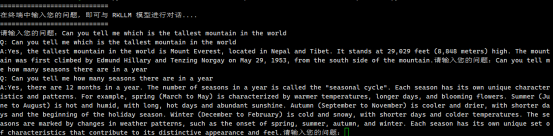
Use the Qwen model on the server side of the development board and test it on the Ubuntu PC side, as shown in the following figure:


- Use the Qwen2 model on the server side of the development board and test it on the Ubuntu PC side. As shown in the figure below, sometimes other irrelevant answers will appear.

Use the Phi-3 model on the server side of the development board and test it on the Ubuntu PC side, as shown in the following figure:

Use the ChatGLM3 model on the server side of the development board and test it on the Ubuntu PC side, as shown in the following figure:
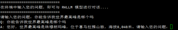
Use the Gemma model on the server side of the development board and test it on the Ubuntu PC side, as shown in the following figure:
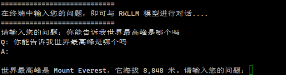
Use the InternLM2 model on the server side of the development board and test it on the Ubuntu PC side, as shown in the following figure:
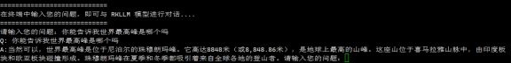
Use the MiniCPM model on the server side of the development board and test it on the Ubuntu PC side, as shown in the following figure:


MiniCPM uses this method very poorly and is not recommended.

Building a server based on Gradio
Server side (development board side)
- First, upload the rkllm-runtime/examples/rkllm_server_demo/rkllm_server folder and the converted .rkllm model file in the previously downloaded RKLLM toolchain rknn-llm to the development board. Upload the .rkllm model file of the large model you want to use.
orangepi@orangepi:~$ ls
Qwen2.rkllm Qwen.rkllm rkllm_server TinyLlama.rkllm
- Then modify rkllm_lib = ctypes.CDLL('lib/librkllmrt.so') in the rkllm_server/gradio_server.py file to rkllm_lib = ctypes.CDLL('/usr/lib/librkllmrt.so'), and modify rknnllm_param.use_gpu = True to rknnllm_param.use_gpu = False.
orangepi@orangepi:~$ vim rkllm_server/gradio_server.py
rkllm_lib = ctypes.CDLL('/usr/lib/librkllmrt.so')
rknnllm_param.use_gpu = False
- Then install the pip library and gradio library on the development board.
That is, the following command:
pip3 install gradio>=4.24.0 -i https://pypi.tuna.tsinghua.edu.cn/simple --break-system-packages
orangepi@orangepi:~$ sudo apt update
orangepi@orangepi:~$ sudo apt install python3-pip -y
orangepi@orangepi:~$ pip3 install gradio>=4.24.0 -i https://pypi.tuna.tsinghua.edu.cn/simple
- Then switch to the rkllm_server directory and run gradio_server.py to start the service
rkllm_model_path is the absolute path to the converted model.
If you want to use TinyLlama, change --rkllm_model_path ~/Qwen.rkllm to --rkllm_model_path ~/TinyLlama.rkllm.
If you want to use Qwen2, change --rkllm_model_path ~/Qwen.rkllm to --rkllm_model_path ~/Qwen2.rkllm.
If you want to use Phi-3, change --rkllm_model_path ~/Qwen.rkllm to --rkllm_model_path ~/Phi3.rkllm.
If you want to use ChatGLM3, change --rkllm_model_path ~/Qwen.rkllm to --rkllm_model_path ~/chatglm3.rkllm.
If you want to use Gemma, change --rkllm_model_path ~/Qwen.rkllm to --rkllm_model_path ~/Gemma.rkllm.
If you want to use InternLM2, change --rkllm_model_path ~/Qwen.rkllm to --rkllm_model_path ~/InternLM2.rkllm.
If you want to use MiniCPM, change --rkllm_model_path ~/Qwen.rkllm to --rkllm_model_path ~/MiniCPM.rkllm.
orangepi@orangepi:~$ cd rkllm_server
orangepi@orangepi:~/rkllm_server$ python3 gradio_server.py --target_platform rk3588 --rkllm_model_path ~/Qwen.rkllm
- If successful, it will be as shown in the figure below. At this time, the server is configured.
The http://0.0.0.0:8080 in the figure does not mean that the IP address is this. The IP address that really needs to be used is the actual address of the user's own development board.

Client
- First, open the browser on any computer in the current LAN and directly access "Development Board IP:8080". The opened interface is as shown below:

- Then enter the question in the inputTextBox and press Enter.

- Use the TinyLLAMA model on the server side of the development board and test it on the Ubuntu PC side, as shown in the following figure:

- Use the Qwen model on the server side of the development board and test it on the Ubuntu PC side, as shown in the following figure:

- Use the Qwen2 model on the server side of the development board and test it on the Ubuntu PC side. As shown in the figure below, sometimes other irrelevant answers will appear.

Use the Phi-3 model on the server side of the development board and test it on the Ubuntu PC side, as shown in the following figure:

Use the ChatGLM3 model on the server side of the development board and test it on the Ubuntu PC side, as shown in the following figure:

Use the Gemma model on the server side of the development board and test it on the Ubuntu PC side, as shown in the following figure:

Use the InternLM2 model on the server side of the development board and test it on the Ubuntu PC side, as shown in the following figure:

Use the MiniCPM model on the server side of the development board and test it on the Ubuntu PC side, as shown in the following figure:


Performance test results of RK3588 running RKLLM large model
In order to perform large model performance testing, you first need to download the large model performance test file main.cpp in the official tool. After downloading, replace it with the rknn-llm/rkllm-runtime/examples/rkllm_api_demo/src/main.cpp file used by the PC to compile the test code
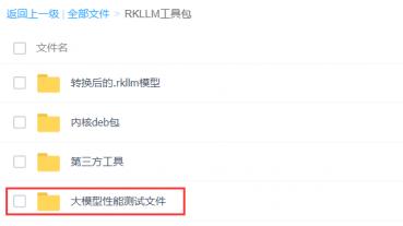
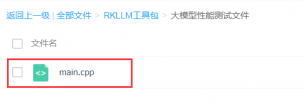
Refer to the Compiling the test code section to recompile the llm_demo file, and then run the large model according to the detailed steps for deployment and operation on the development board section.
After the model runs, enter a question and then open a new terminal to test the performance. The performance test is when the model answers the question.
NPU load test: Use another terminal to run the following command while the model is answering questions:


orangepi@orangepi:~$ sudo cat /sys/kernel/debug/rknpu/load
NPU load: Core0: 51%, Core1: 51%, Core2: 51%,
- CPU load, memory: Use another terminal to run the following commands while the model is answering questions:
When calculating the CPU load, divide the CPU% value of the llm_demo process by the number of CPUs.
When calculating memory, use the MEM% value of the llm_demo process * the total MEM
You can click on the CPU option and the interface will be displayed in descending order based on CPU usage.

orangepi@orangepi:~$ htop

Reasoning: Reasoning speed, referred to as reasoning, is the number of tokens output during model reasoning/the time taken for model reasoning. The test results are printed in the terminal where the large model is running, as shown in the following figure:
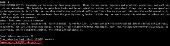
Pre-fill: Calculate the number of input tokens/time from model running to output of the first token. Use the given problem as input, and the test results will be printed in the terminal where the large model is running.

Since different large language models may use different word segmentation strategies when processing the same sentence, resulting in differences in the number of generated tokens, and RKLLM does not provide a corresponding channel for obtaining the actual number of input tokens, we used GPT to generate questions with 256 tokens as input, resulting in a certain error in the test results.
Q: In the field of deep learning, what are the key differences between convolutional neural networks (CNNs) and recurrent neural networks (RNNs) in processing images and time series data? Please explain in detail the main features of each network structure, including how they are applied in different types of tasks, such as image recognition, natural language processing, and time series prediction. In addition, discuss how these networks deal with overfitting problems and how regularization techniques such as dropout can be used to improve the generalization ability of the model. Finally, explore how these networks are combined with other models such as Transformers in current artificial intelligence research to solve complex machine learning problems, and give some successful examples of these models in practical applications.

- The test results of all models are shown in the following table:
| Model | Mem ory | d typ e | performance | C PU
Lo ad |
N PU
Lo ad |
Memory u sage |
| Ti nyLLAMA | 1.1B | W 8a8 | pr efilled:58.6157 token/s
in ference:12.7262 token/s |
1 5.9% | 3
|
1.376G |
| Qwen | 1.8B | W 8a8 | pr efilled:168.525 token/s
in ference:10.8891 token/s |
1 3.7% | 3
|
2.72G |
| Qwen2 | 0.5B | W 8a8 | pr efilled:440.511 token/s
in ference:17.4542 token/s |
17 .75% | 3
|
1.344G |
| Phi-3 | 3.8B | W 8a8 | pr efilled:22.8119 token/s
in ference:4.72983 token/s |
13 .13% | 3
|
4.288G |
| C hatGLM3 | 6B | W 8a8 | pr efilled:48.8464 token/s
in ference:3.80383 token/s |
8.3% | 3
|
7.04G |
| Gemma | 2B | W 8a8 | pr efilled:112.489 token/s
in ference:6.41746 token/s |
8 .25% | 3
|
4.8G |
| In ternLM2 | 1.8B | W 8a8 | pr efilled:117.099 token/s
inference:9.139 token/s |
11 .87% | 3
|
2.432G |
| MiniCPM | 2B | W 8a8 | pr efilled:77.4655 token/s
in ference:6.16648 token/s |
16 .25% | 3
|
3.904G |
How to shut down and restart the development board
When the Linux system is running, if you unplug the Type-C power directly to cut off the power, the file system may lose some data or be damaged. Therefore, please use the poweroff command to shut down the Linux system of the development board before unplugging the power.
orangepi@orangepi:~$ sudo poweroff
In addition, the development board is equipped with a power button, and you can also short press the power button on the development board to shut down.
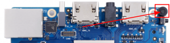

Note that when you press the power button on the Linux desktop system, a confirmation box as shown in the figure below will pop up. You need to click the Shut Down option before shutting down.

After shutting down, short press the power button on the development board to turn it on.
The command to restart the Linux system is:
orangepi@orangepi:~$ sudo reboot
Orange Pi OS Arch system usage instructions
Orange Pi OS Arch system compatibility
| Function | OPi OS Arch Gnome Wayland |
| HDMI TX video | OK |
| HDMI TX Audio | OK |
| HDMI RX video | OK |
| HDMI RX Audio | OK |
| USB2.0x2 | OK |
| USB3.0x2 | OK |
| 2.5G Network port | OK |
| Network port status light | OK |
| WIFI | OK |
| Bluetooth | OK |
| Debug serial port | OK |
| RTC | OK |
| Fan connector | OK |
| eMMC expansion interface | OK |
| GPIO(40pin) | OK |
| UART(40pin) | OK |
| SPI(40pin) | OK |
| I2C(40pin) | OK |
| CAN(40pin) | OK |
| PWM(40pin) | OK |
| TF card boot | OK |
| OV13850 Camera | OK |
| OV13855 Camera | OK |
| SPI+NVME boot | OK |
| LCD | OK |
| MIC | OK |
| Headphone playback | OK |
| Headphone Recording | OK |
| Three-color LED light | OK |
| GPU | OK |
| NPU | NO |
| VPU | OK |
| Power button | OK |
| Watchdog test | OK |
| MPV hard decoding video | OK |
10.1-inch MIPI LCD screen usage
10.1 inch MIPI screen assembly method
First prepare the necessary accessories
inch MIPI LCD display + touch screen

Screen adapter board + 31pin to 40pin cable

30pin MIPI cable

12pin touch screen cable
Connect the 12-pin touch screen cable, 31-pin to 40-pin cable, and 30-pin MIPI cable to the screen adapter board as shown below. Note that the blue insulation side of the touch screen cable should face down, and the insulation sides of the other two cables should face up. If connected incorrectly, it will cause no display or inability to touch.

Place the adapter board with the connected cable on the MIPI LCD screen as shown below, and connect the MIPI LCD screen and the adapter board via a 31pin to 40pin cable.
Then connect the touch screen and the adapter board through the 12-pin touch screen cable, paying attention to the direction of the insulating surface
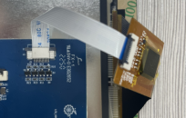
Finally, connect it to the LCD interface of the development board through the 30pin MIPI cable
How to open the 10.1-inch MIPI LCD screen configuration
The OPi OS Arch image does not have the mipi LCD screen configuration turned on by default. If you need to use the mipi LCD screen, you need to turn it on manually.
The interface of the mipi lcd screen on the development board is shown in the figure below:
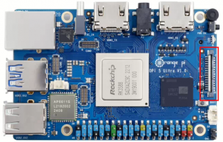
The method to open the mipi lcd configuration is as follows:
[orangepi@orangepi ~]$ sudo vim /boot/extlinux/extlinux.conf
LABEL Orange Pi
LINUX /Image
FDT /dtbs/rockchip/rk3588-orangepi-5-ultra.dtb
FDTOVERLAYS /dtbs/rockchip/overlay/rk3588-opi5ultra-lcd.dtbo #Configuration that needs to be added
Then restart the OPi OS Arch system
After restarting, you can see the display of the LCD screen as shown below (the default is vertical screen):

Methods for rotating display and touch direction
First click on the area in the upper right corner of the desktop

Then open Settings
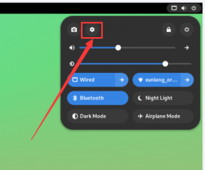
Then select Displays
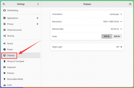
Then select the direction you want to rotate in Orientation of Displays
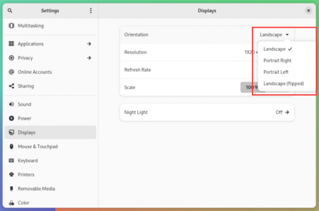
Then select Apply
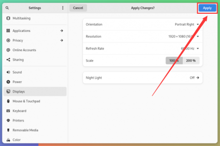
Then you can see that the screen has been rotated. At this time, you need to select Keep Changes to finalize the rotation.
The LCD screen is rotated 90 degrees and the display is as follows:

The touch function of the LCD screen of the OPi OS Arch system will rotate with the rotation of the display direction, and no other settings are required


Test methods for OV13850 and OV13855 MIPI cameras
Currently the development board supports two MIPI cameras, OV13850 and OV13855. The specific pictures are shown below:
13MP OV13850 camera with MIPI interface

13MP OV13855 camera with MIPI interface
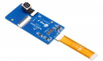
The adapter board and FPC cable used by the OV13850 and OV13855 cameras are the same, but the two cameras are connected to the adapter board in different positions. The FPC cable is shown in the figure below. Please note that the FPC cable has a direction. The end marked with TO MB needs to be plugged into the camera interface of the development board, and the end marked with TO CAMERA needs to be plugged into the camera adapter board.
There are 3 camera interfaces on the camera adapter board. Only one camera can be connected at a time, as shown in the following figure.:
Interface 1 is connected to the OV13850 camera
Interface 2 is connected to the OV13855 camera
Interface 3 is not used, just ignore it
There are three camera interfaces on the Orange Pi 5 Ultra development board. We define the positions of Cam0, Cam1, and Cam2 as shown in the following figure.:
The method of inserting the camera into the Cam0 interface of the development board is as follows:
The method of inserting the camera into the Cam1 interface of the development board is as follows:
The method of inserting the camera into the Cam2 interface of the development board is as follows:
After connecting the camera to the development board, we can use the following method to test the camera:
First add the following configuration to /boot/extlinux/extlinux.conf
[orangepi@orangepi ~]$ sudo vim /boot/extlinux/extlinux.conf
LABEL Orange Pi
LINUX /Image
FDT /dtbs/rockchip/rk3588-orangepi-5-ultra.dtb
FDTOVERLAYS /dtbs/rockchip/overlay/rk3588-opi5ultra-cam0.dtbo #Configuration that needs to be added
The red font above shows the configuration of opening the Cam0 interface. The configuration of other interfaces is shown in the following table. Add the corresponding dtbo configuration after FDTOVERLAYS. If you want to add multiple configurations at the same time, separate them with spaces.
| Camera | Configuration of dtbo |
| Cam0 | /dtbs/rockchip/overlay/rk3588-opi5ultra-cam0.dtbo |
| Cam1 | /dtbs/rockchip/overlay/rk3588-opi5ultra-cam1.dtbo |
| Cam2 | /dtbs/rockchip/overlay/rk3588-opi5ultra-cam2.dtbo |
Then restart the OPi OS Arch system
Then open a terminal in the desktop system and run the following script
orangepi@orangepi:~$ test_camera.sh
Then you can see the camera preview screen
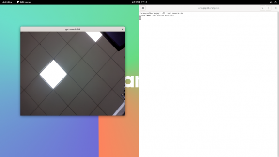

How to set up the Chinese environment and install the Chinese input method
First click on the area in the upper right corner of the desktop

Then open Settings
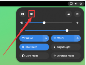
Then find the System option
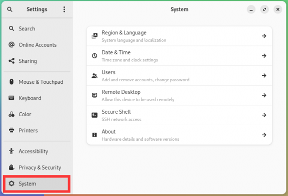
Then select Region & Language
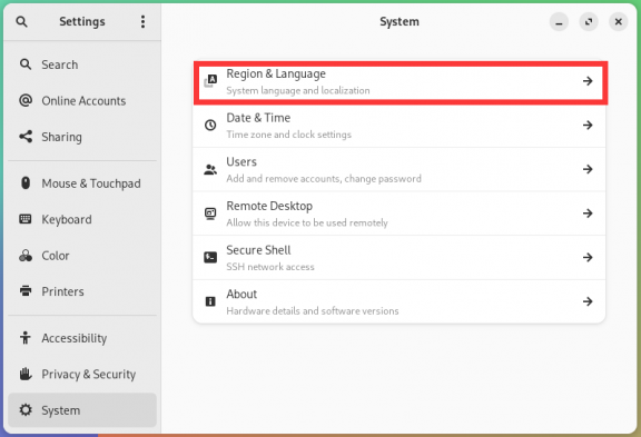
Then select Language

Then select Chinese
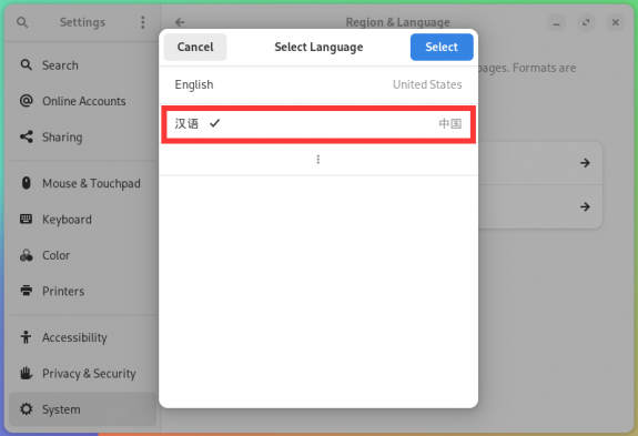
Then clickSelect
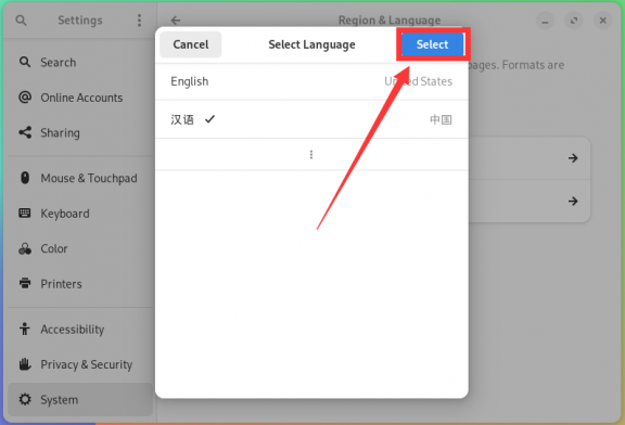
Then click Log Out... to log out of the system and then log in again
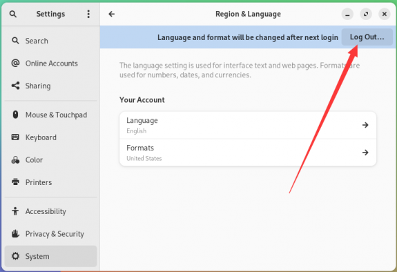
Then you can see that the desktop is displayed in Chinese
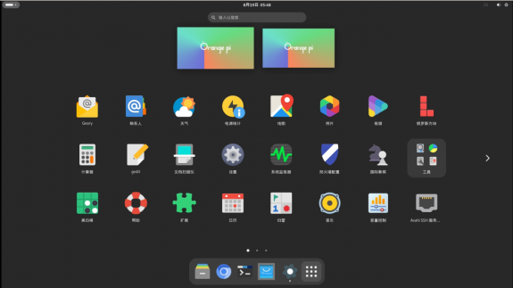
Then install fcitx-im and fcitx-configtool
[orangepi@orangepi ~]$ sudo pacman -S fcitx-im fcitx-configtool
:: There are 3 members in the group fcitx-im:
:: Software Repository community
1) fcitx 2) fcitx-qt5 3) fcitx-qt6
Enter a selection (default = select all): 1
Then open the Fcitx configuration program
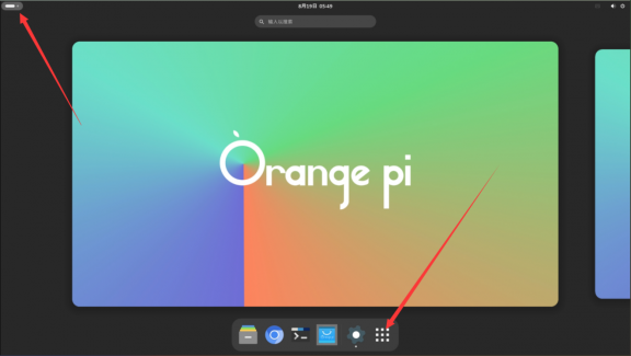
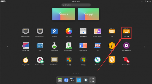
Then add Google Pinyin input method
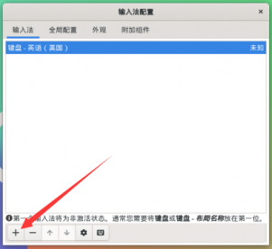
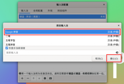
Then we can open a terminal to test the Chinese input method. After opening the terminal, if the default input method is still English, we can switch to the Chinese input method by pressing Ctrl+Space, and then we can enter Chinese.
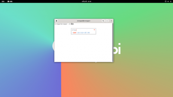


How to install wiringOP
Note that wiringOP is pre-installed in the OPi OS Arch image released by Orange Pi. Unless the wiringOP code is updated, you do not need to download, compile and install it again. You can use it directly.
After entering the system, you can run the gpio readall command. If you can see the following output, it means wiringOP has been pre-installed and can be used normally.

Download the wiringOP code
[orangepi@orangepi ~]$ sudo pacman -Syy git
[orangepi@orangepi ~]$ git clone https://github.com/orangepi-xunlong/wiringOP.git -b next
Note that Orange Pi 5 Ultra needs to download the wiringOP next branch code, please do not miss the -b next parameter.
If you have problems downloading the code from GitHub, you can download the wiringOP.tar.gz source code package from the official tool on the Orange Pi 5 Ultra download page.
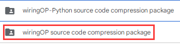
Compile and install wiringOP
[orangepi@orangepi ~]$ sudo pacman -Syy make gcc
[orangepi@orangepi ~]$ cd wiringOP
[orangepi@orangepi wiringOP]$ sudo ./build clean
[orangepi@orangepi wiringOP]$ sudo ./build
Test the output of the gpio readall command as follows
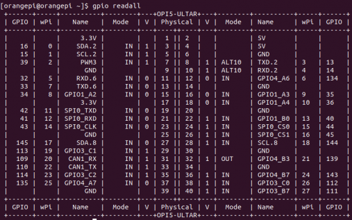

40pin interface GPIO, I2C, UART, SPI, CAN and PWM test
Note that if you need to set fdt overlays to open multiple configurations at the same time, please write them in one line separated by spaces as shown in the red font configuration below.
[orangepi@orangepi ~]$ sudo vim /boot/extlinux/extlinux.conf
LABEL Orange Pi
LINUX /Image
FDT /dtbs/rockchip/rk3588-orangepi-5-ultra.dtb
FDTOVERLAYS /dtbs/rockchip/overlay/rk3588-i2c2-m0.dtbo /dtbs/rockchip/overlay/rk3588-uart4-m2.dtbo
40pin GPIO port test
There are a total of 28 GPIO ports available in the 40 pins of the development board. The following uses pin 7, which corresponds to GPIO GPIO1_A7 and wPi serial number 2, as an example to demonstrate how to set the high and low levels of the GPIO port.
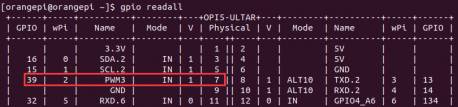
First set the GPIO port to output mode, where the third parameter needs to input the wPi number corresponding to the pin
[orangepi@orangepi ~]$ gpio mode 2 out
Then set the GPIO port to output a low level. After setting, you can use a multimeter to measure the voltage value of the pin. If it is 0v, it means that the low level is set successfully.
[orangepi@orangepi ~]$ gpio write 2 0
Using gpio readall, you can see that the value of pin 7 (V) has changed to 0

Then set the GPIO port to output a high level. After setting, you can use a multimeter to measure the voltage value of the pin. If it is 3.3v, it means that the high level is set successfully.
[orangepi@orangepi ~]$ gpio write 2 1
Using gpio readall, you can see that the value of pin 7 (V) has changed to 1
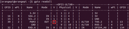
The setting method of other pins is similar. Just change the serial number of wPi to the serial number corresponding to the pin.


40Pin GPIO port pull-up and pull-down resistor settings
Note that the following 10 GPIO pins of Orange Pi 5 Ultra have external 3.3V pull-up, so setting the pull-down is invalid.

Below, we take pin 11, which corresponds to GPIO GPIO1_A0 and wPi number 5, as an example to demonstrate how to set the pull-up and pull-down resistors of the GPIO port.
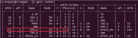
First, you need to set the GPIO port to input mode. The third parameter needs to enter the wPi number corresponding to the pin.
[orangepi@orangepi ~]$ gpio mode 5 in
After setting to input mode, execute the following command to set the GPIO port to pull-up mode
[orangepi@orangepi ~]$ gpio mode 5 up
Then enter the following command to read the level of the GPIO port. If the level is 1, it means that the pull-up mode is set successfully.
[orangepi@orangepi ~]$ gpio read 5
1
Then execute the following command to set the GPIO port to pull-down mode
[orangepi@orangepi ~]$ gpio mode 5 down
Then enter the following command to read the level of the GPIO port. If the level is 0, it means that the pull-down mode is set successfully.
[orangepi@orangepi ~]$ gpio read 5
0

40pin SPI test
- As shown in the figure below, the available spis for Orange Pi 5 Ultra are spi0, spi1 and spi4

- The corresponding pins of SPI0, SPI1 and SPI4 in 40 pins are shown in the following table.
| SPI0_M2 corresponds to 40pin | SPI1_M1 corresponds to 40pin | SPI4_M2 corresponds to 40pin | |
| MOSI | Pin 19 | Pin 40 | Pin 13 |
| MISO | Pin 21 | Pin 38 | Pin 11 |
| CLK | Pin 23 | Pin 29 | Pin 15 |
| CS0 | Pin 24 | Pin 35 | Pin 16 |
| CS1 | Pin 26 | None | None |
| dtbo confi guration | spi 0-m2-cs0-spidev
spi 0-m2-cs1-spidev spi0-m2 -cs0-cs1-spidev |
spi1 -m1-cs0-spidev | spi4 -m2-cs0-spidev |
In OPi OS Arch system, the spi function in 40pin is disabled by default and needs to be enabled manually before it can be used.
Add the following configuration in red font to /boot/extlinux/extlinux.conf, and then restart the OPi OS Arch system to enable spi0, spi1 and spi4. If you only need to open one, just fill in one.
[orangepi@orangepi ~]$ sudo vim /boot/extlinux/extlinux.conf
LABEL Orange Pi
LINUX /Image
FDT /dtbs/rockchip/rk3588-orangepi-5-ultra.dtb
FDTOVERLAYS /dtbs/rockchip/overlay/rk3588-spi0-m2-cs0-cs1-spidev.dtbo
/dtbs/rockchip/overlay/rk3588-spi1-m1-cs0-spidev.dtbo
/dtbs/rockchip/overlay/rk3588-spi4-m2-cs0-spidev.dtbo
First check whether there is a device node of spidevx.x in the OPi OS Arch system. If it exists, it means that SPI has been set up and can be used directly
[orangepi@orangepi ~]$ ls /dev/spidev*
/dev/spidev0.0 /dev/spidev0.1 /dev/spidev1.0 /dev/spidev4.0
The above is the result after opening spi0-m2-cs0-cs1-spidev, spi1-m1-cs0-spidev and spi4-m2-cs0-spidev.
Do not short the mosi and miso pins of SPI0, SPI1 or SPI4. The output of running spidev_test is as follows. You can see that the data of TX and RX are inconsistent.
[orangepi@orangepi ~]$ sudo spidev_test -v -D /dev/spidev0.0 #spi0 commands
[orangepi@orangepi ~]$ sudo spidev_test -v -D /dev/spidev1.0 #spi1 commands
[orangepi@orangepi ~]$ sudo spidev_test -v -D /dev/spidev4.0 #spi4 commands
spi mode: 0x0
bits per word: 8
max speed: 500000 Hz (500 KHz)
TX | FF FF FF FF FF FF 40 00 00 00 00 95 FF FF FF FF FF FF FF FF FF FF FF FF FF FF FF FF FF FF F0 0D | ......@.…▒..................▒.
RX | FF FF FF FF FF FF FF FF FF FF FF FF FF FF FF FF FF FF FF FF FF FF FF FF FF FF FF FF FF FF FF FF | ............................….
Then short the mosi and miso pins of SPI0, SPI1 or SPI4 and run spidev_test. The output is as follows. You can see that the data sent and received are the same.
[orangepi@orangepi ~]$ sudo spidev_test -v -D /dev/spidev0.0 #spi0 commands
[orangepi@orangepi ~]$ sudo spidev_test -v -D /dev/spidev1.0 #spi1 commands
[orangepi@orangepi ~]$ sudo spidev_test -v -D /dev/spidev4.0 #spi4 commands
spi mode: 0x0
bits per word: 8
max speed: 500000 Hz (500 KHz)
TX | FF FF FF FF FF FF 40 00 00 00 00 95 FF FF FF FF FF FF FF FF FF FF FF FF FF FF FF FF FF FF F0 0D | ......@.…▒..................▒.
RX | FF FF FF FF FF FF 40 00 00 00 00 95 FF FF FF FF FF FF FF FF FF FF FF FF FF FF FF FF FF FF F0 0D | ......@.…▒..................▒.
40pin I2C test
As can be seen from the table below, Orange Pi 5 Ultra has four i2c buses: i2c2, i2c4, i2c5 and i2c8
The corresponding pins of the 4 groups of I2C buses in 40 pins are shown in the following table. I2C2_M0 and I2C2_M4 can only use one of them at the same time, not both. They are the same I2C, just connected to different pins. Please do not think that they are two different I2C buses.
| I2C bus | SDA correspond 40pin | SCL correspond 40pin | Dtbo Corresponding configuration |
| I2C2_M0 | Pin 3 | Pin 5 | i2c2-m0 |
| I2C2_M4 | Pin11 | Pin 13 | i2c2-m4 |
| I2C4_M3 | Pin15 | Pin16 | i2c4-m3 |
| I2C5_M2 | Pin37 | Pin12 | i2c5-m2 |
| I2C8_M3 | Pin27 | Pin28 | i2c8-m3 |
In OPi OS Arch system, the i2c in 40pin is disabled by default and needs to be enabled manually before it can be used.
Add the following configuration in red font to /boot/extlinux/extlinux.conf, then restart the OPi OS Arch system to enable i2c2, i2c4, i2c5 and i2c8 at the same time. If you only need to open one, just fill in one.
[orangepi@orangepi ~]$ sudo vim /boot/extlinux/extlinux.conf
LABEL Orange Pi
LINUX /Image
FDT /dtbs/rockchip/rk3588-orangepi-5-ultra.dtb
FDTOVERLAYS /dtbs/rockchip/overlay/rk3588-i2c2-m0.dtbo /dtbs/rockchip/overlay/rk3588-i2c4-m3.dtbo /dtbs/rockchip/overlay/rk3588-i2c5-m2.dtbo
/dtbs/rockchip/overlay/rk3588-i2c8-m3.dtbo
The red font configurations above need to be written in one line, and different configurations need to be separated by spaces.
After booting the OPi OS Arch system, first confirm that the i2c device node exists under /dev
[orangepi@orangepi ~]$ ls /dev/i2c-*
/dev/i2c-0 /dev/i2c-10 /dev/i2c-4 /dev/i2c-6 /dev/i2c-9
/dev/i2c-1 /dev/i2c-2 /dev/i2c-5 /dev/i2c-7 /dev/i2c-8
Then connect an i2c device to the i2c pin of the 40pin connector
Generally, you only need to connect one of the 3.3v pin and the 5v pin. Please choose to connect the 3.3v pin or the 5v pin according to the specific i2c device you are connecting.
Then use the i2cdetect -y command. If the address of the connected i2c device can be detected, it means that i2c can be used normally.
[orangepi@orangepi ~]$ sudo pacman -Syy i2c-tools
[orangepi@orangepi ~]$ sudo i2cdetect -y 2 #i2c2 commands
[orangepi@orangepi ~]$ sudo i2cdetect -y 4 #i2c4 commands
[orangepi@orangepi ~]$ sudo i2cdetect -y 5 #i2c5 commands
[orangepi@orangepi ~]$ sudo i2cdetect -y 8 #i2c8 commands
40pin UART Test
As shown in the table below, the Orange Pi 5 Ultra has three sets of UART buses available: UART 3, UART 4, and UART 6. UART 2 is used for debugging serial port functions and is not included in the calculation.
The corresponding pins of the four UART buses in the 40 pin configuration are shown in the table below.
| UART bus | RX corresponds to 40 pins | TX corresponds to 40 pins | Dtbo corresponding configuration |
| UART3_M1 | Pin 33 | Pin 31 | uart3-m1 |
| UART4_M2 | Pin 19 | Pin 23 | uart4-m2 |
| UART6_M1 | Pin 11 | Pin 13 | uart6-m1 |
In the OPi OS Arch system, UART in 40pin is turned off by default and needs to be manually turned on to use.
Add the configuration in red font below to/boot/extlinux/extlinux.conf, and then restart the OPi OS Arch system to open UART 3, UART 4, and UART 6 simultaneously. If only one needs to be opened, fill in one.
[orangepi@orangepi ~]$ sudo vim /boot/extlinux/extlinux.conf
LABEL Orange Pi
LINUX /Image
FDT /dtbs/rockchip/rk3588-orangepi-5-ultra.dtb
FDTOVERLAYS /dtbs/rockchip/overlay/rk3588-uart3-m1.dtbo /dtbs/rockchip/overlay/rk3588-uart4-m2.dtbo /dtbs/rockchip/overlay/rk3588-uart6-m1.dtbo
The red font configuration above needs to be written on one line, and different configurations need to be separated by spaces.
After entering the Linux system, first confirm whether there is a device node corresponding to UART in/dev
[orangepi@orangepi ~]$ ls /dev/ttyS*
/dev/ttyS3 /dev/ttyS4 /dev/ttyS6 /dev/ttyS7
Then start testing the UART interface by short circuiting the RX and TX of the UART interface to be tested using DuPont wires
Use the gpio serial command to test the loopback function of the serial port as shown below. If you can see the print below, it indicates that the serial communication is normal (ttySX needs to be replaced with the corresponding UART node name, please do not copy it)
[orangepi@orangepi ~]$ sudo gpio serial /dev/ttySX
Out: 0: -> 0
Out: 1: -> 1
Out: 2: -> 2
Out: 3: -> 3
Out: 4: -> 4
Out: 5: -> 5^C
PWM Testing Method
From the table below, it can be seen that the Orange Pi 5 Ultra has seven PWM channels available, including PWM 0, PWM 1, PWM 3, PWM 6, PWM 12, PWM 13, and PWM 14
- The corresponding pins of PWM in 40 pins are shown in the table below. PWM0.M0 and PWM0-M2, as well as PWM1_M0 and PWM1_M2, can only be used one at a time and cannot be used simultaneously. They are all the same PWM, just connected to different pins. Please do not assume that they are two different PWM buses.
| PWM bus | Corresponding to 40 pins | Dtbo corresponding configuration |
| PWM0_M0 | Pin 5 | pwm0-m0 |
| PWM0_M2 | Pin 15 | pwm0-m2 |
| PWM1_M0 | Pin 3 | pwm1-m0 |
| PWM1_M2 | Pin 16 | pwm1-m2 |
| PWM3_M3 | Pin 7 | pwm3-m3 |
| PWM6_M1 | Pin 27 | pwm6-m1 |
| PWM12_M0 | Pin 31 | pwm12-m0 |
| PWM13_M0 | Pin 33 | pwm13-m0 |
| PWM14_M0 | Pin 35 | pwm14-m0 |
In the OPi OS Arch system, the PWM in the 40pin is turned off by default and needs to be manually turned on to use.
Add the configuration in red font below to/boot/extlinux/extlinux.conf, and then restart the OPi OS Arch system to simultaneously open pwm0, pwm1, pwm3, pwm6, pwm12, pwm13, and pwm14. If only one needs to be opened, fill in one.
[orangepi@orangepi ~]$ sudo vim /boot/extlinux/extlinux.conf
LABEL Orange Pi
LINUX /Image
FDT /dtbs/rockchip/rk3588-orangepi-5-ultra.dtb
FDTOVERLAYS /dtbs/rockchip/overlay/rk3588-pwm0-m0.dtbo
/dtbs/rockchip/overlay/rk3588-pwm1-m0.dtbo /dtbs/rockchip/overlay/rk3588-pwm3-m3.dtbo /dtbs/rockchip/overlay/rk3588-pwm6-m1.dtbo /dtbs/rockchip/overlay/rk3588-pwm12-m0.dtbo /dtbs/rockchip/overlay/rk3588-pwm13-m0.dtbo /dtbs/rockchip/overlay/rk3588-pwm14-m0.dtbo
The red font configuration above needs to be written on one line, and different configurations need to be separated by spaces.
When a PWM is turned on, an additional pwmchipX (where X is a specific number) will appear in/sys/class/pwm/. For example, when opening pwm3, checking the pwmchipX under/sys/class/pwm/will change from two to three
[orangepi@orangepi ~]$ ls /sys/class/pwm/
pwmchip0 pwmchip1 pwmchip2
Which pwmchip corresponds to pwm3 above? Let's first check the output of the ls /sys/class/pwm/ -l command, as shown below:
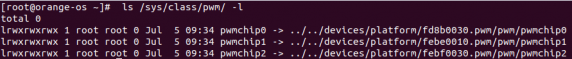
Then, as shown in the table below, the base address of the pwm3 register is fd8b0030. Looking at the output of the ls /sys/class/pwm/ -l command, it can be seen that pwmchip0 is linked to fd8b0030. pwm, so pwm3 corresponds to pwmchip0
Then use the following command to make pwm3 output a 50Hz square wave (please switch to the root user first, and then execute the following command)

[root@orangepi orangepi]# echo 0 > /sys/class/pwm/pwmchip0/export
[root@orangepi orangepi]# echo 20000000 > /sys/class/pwm/pwmchip0/pwm0/period
[root@orangepi orangepi]# echo 1000000 > /sys/class/pwm/pwmchip0/pwm0/duty_cycle
[root@orangepi orangepi]# echo 1 > /sys/class/pwm/pwmchip0/pwm0/enable
- The testing method for PWM 3 demonstrated above is similar to other PWM testing methods.
Testing Methods for CAN
According to the table below, the Orange Pi 5 Ultra can use two sets of CAN buses, CAN0 and CAN1
In the OPi OS Arch system, the CAN in the 40pin is turned off by default and needs to be manually turned on to use.
Add the configuration in red font below to/boot/extlinux/extlinux.conf, and then restart the OPi OS Arch system to enable CAN0 and CAN1.
[orangepi@orangepi ~]$ sudo vim /boot/extlinux/extlinux.conf
LABEL Orange Pi
LINUX /Image
FDT /dtbs/rockchip/rk3588-orangepi-5-ultra.dtb
FDTOVERLAYS /dtbs/rockchip/overlay/rk3588-can0-m0.dtbo
/dtbs/rockchip/overlay/rk3588-can1-m0.dtbo
The red font configuration above needs to be written on one line, and different configurations need to be separated by spaces.
After entering the OPi OS Arch system, use the sudo ifconfig -a command. If you can see the device nodes of CAN, it means that CAN has been opened correctly
[orangepi@orangepi ~]$ sudo pacman -Syy net-tools
[orangepi@orangepi ~]$ sudo ifconfig -a
can0: flags=128<NOARP> mtu 16
unspec 00-00-00-00-00-00-00-00-00-00-00-00-00-00-00-00 txqueuelen 10 (UNSPEC)
RX packets 0 bytes 0 (0.0 B)
RX errors 0 dropped 0 overruns 0 frame 0
TX packets 0 bytes 0 (0.0 B)
TX errors 0 dropped 0 overruns 0 carrier 0 collisions 0
device interrupt 91
can1: flags=128<NOARP> mtu 16
unspec 00-00-00-00-00-00-00-00-00-00-00-00-00-00-00-00 txqueuelen 10 (UNSPEC)
RX packets 0 bytes 0 (0.0 B)
RX errors 0 dropped 0 overruns 0 frame 0
TX packets 0 bytes 0 (0.0 B)
TX errors 0 dropped 0 overruns 0 carrier 0 collisions 0
device interrupt 92
The pins corresponding to CAN0 and CAN1 are
| CAN0 | CAN1 | |
| TX pin | Corresponding to pin 5 | Corresponding to pin 33 |
| RX pin | Corresponding to pin 3 | Corresponding to pin 31 |
- Please refer to the section on testing CAN sending and receiving messages using CANalyst II analyzer for the method.
Linux SDK - Orangepi build usage instructions
Compile System Requirements
We can cross compile the Linux image of the development board on an x64 computer, or compile the Linux image of the development board on the Ubuntu 22.04 system. Please choose one according to your preferences.
If using orangepi build to compile Linux images on the Ubuntu 22.04 system of the development board, please ensure proper cooling (especially during SSD startup). If the heat dissipation is not done properly, it is easy to cause file system runaway errors.
Compile using the Ubuntu 22.04 system on the development board
The Linux SDK, also known as orangepi-build, supports running on Ubuntu 22.04 on the development board (which has not been tested on other systems), so before downloading orangepi build, please ensure that the Ubuntu version installed on the development board is Ubuntu 22.04. The command to check the installed Ubuntu version on the development board is as follows. If the Release field does not display 22.04, it means that the current Ubuntu version used does not meet the requirements. Please replace the system before performing the following operations.
orangepi@orangepi:~$ lsb_release -a
No LSB modules are available.
Distributor ID: Ubuntu
Description: Ubuntu 22.04.1 LTS
Release: 22.04
Codename: jammy
Since the kernel and U-boot source code are stored on GitHub, it is important to ensure that the development board can download the code from GitHub properly when compiling the image.
Compile on Ubuntu 22.04 computer using x64
The Linux SDK, also known as orangepi-build, supports running on computers with Ubuntu 22.04 installed. Therefore, before downloading orangepi build, please make sure that the Ubuntu version installed on your computer is Ubuntu 22.04. The command to check the installed Ubuntu version on the computer is as follows. If the Release field does not display 22.04, it means that the current Ubuntu version used does not meet the requirements. Please replace the system before performing the following operations.
test@test:~$ lsb_release -a
No LSB modules are available.
Distributor ID: Ubuntu
Description: Ubuntu 22.04 LTS
Release: 22.04
Codename: jammy
If the computer is installed with a Windows system and does not have Ubuntu 22.04 installed, you can consider using VirtualBox or VMware to install an Ubuntu 22.04 virtual machine on the Windows system. However, please note that do not compile orangepi build on a WSI virtual machine, as orangepi build has not been tested on a WSI virtual machine, so it cannot be guaranteed that orangepi build can be used properly in WSI.
The installation image download address for Ubuntu 22.04 amd64 version is:
https://mirrors.tuna.tsinghua.edu.cn/ubuntu-releases/22.04/ubuntu-22.04.3-desktop-amd64.iso
https://repo.huaweicloud.com/ubuntu-releases/22.04/ubuntu-22.04.3-desktop-amd64.iso
After installing Ubuntu 22.04 on a computer or virtual machine, please first set the software source of Ubuntu 22.04 to Qinghua Source, otherwise errors may occur during software installation due to network issues
- The method of replacing Tsinghua Source can refer to the instructions on this webpage
https://mirrors.tuna.tsinghua.edu.cn/help/ubuntu/
Note that Ubuntu version needs to be switched to 22.04
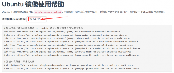
The contents of the/etc/apt/sources.list file that needs to be replaced are
test@test:~$ sudo mv /etc/apt/sources.list /etc/apt/sources.list.bak
test@test:~$ sudo vim /etc/apt/sources.list
# By default, the source code image has been annotated to improve the speed of apt updates. If necessary, you can remove the annotation yourself
deb https://mirrors.tuna.tsinghua.edu.cn/ubuntu/ jammy main restricted universe multiverse
# deb-src https://mirrors.tuna.tsinghua.edu.cn/ubuntu/ jammy main restricted universe multiverse
deb https://mirrors.tuna.tsinghua.edu.cn/ubuntu/ jammy-updates main restricted universe multiverse
# deb-src https://mirrors.tuna.tsinghua.edu.cn/ubuntu/ jammy-updates main restricted universe multiverse
deb https://mirrors.tuna.tsinghua.edu.cn/ubuntu/ jammy-backports main restricted universe multiverse
# deb-src https://mirrors.tuna.tsinghua.edu.cn/ubuntu/ jammy-backports main restricted universe multiverse
deb https://mirrors.tuna.tsinghua.edu.cn/ubuntu/ jammy-security main restricted universe multiverse
# deb-src https://mirrors.tuna.tsinghua.edu.cn/ubuntu/ jammy-security main restricted universe multiverse
# Pre release software source, not recommended to enable
# deb https://mirrors.tuna.tsinghua.edu.cn/ubuntu/ jammy-proposed main restricted universe multiverse
# deb-src https://mirrors.tuna.tsinghua.edu.cn/ubuntu/ jammy-proposed main restricted universe multiverse
After replacement, it is necessary to update the package information and ensure that there are no errors
test@test:~$ sudo apt update
In addition, since the kernel and U-boot source code are stored on GitHub, it is important to ensure that the computer can download the code from GitHub properly when compiling the image.

Obtain the source code of Linux SDK
Download Orangepi build from GitHub
- The Linux SDK actually refers to the Orangepi build code, which is modified based on the armbian build compilation system. Using Orangepi build, multiple versions of Linux images can be compiled. First, download the code for orangepi build. The command is as follows:
test@test:~$ sudo apt-get update
test@test:~$ sudo apt-get install -y git
test@test:~$ git clone https://github.com/orangepi-xunlong/orangepi-build.git -b next
Note that the Orange Pi 5 Ultra development board requires downloading the next branch source code of the orangepi build. The git clone command above needs to specify the branch of the orangepi build source code as next.

Downloading the code for orangepi build through the git clone command does not require entering the username and password of the GitHub account (the same applies to downloading other code in this manual). If Ubuntu PC prompts for the username and password of the GitHub account after entering the git clone command, it is usually due to an incorrect input of the address of the orangepi build repository after git clone. Please carefully check the spelling of the command for errors, rather than thinking that we forgot to provide the username and password of the GitHub account here.
- The u-boot and Linux kernel versions currently used on the development board are as follows
| branch | u-boot version | Linux kernel version |
| legacy | u-boot 2017.09 | linux5.10 |
| current | u-boot 2017.09 | linux6.1 |
The branch mentioned here and the branch of orangepi build source code are not the same thing, please don't confuse them. This branch is mainly used to distinguish between different versions of kernel source code.
At present, we define the linux5.10 bsp kernel provided by RK as the legacy branch, and the linux6.1 bsp kernel as the current branch.
After downloading orangepi build, it will include the following files and folders
build.sh: Compile startup script
external: Contains configuration files required for compiling images, specific scripts, and source code for some programs, etc
LICENSE: GPL 2 License File
README.md: Orangepi build documentation
scripts: General script for compiling Linux images
test@test:~/orangepi-build$ ls
build.sh external LICENSE README.md scripts
If you download the code for Orangepi build from GitHub, you may find that the Orangepi build does not include the source code for u-boot and Linux kernel, nor does it require a cross compilation toolchain to compile u-boot and Linux kernel. This is normal because these things are stored in other separate GitHub repositories or on certain servers (the addresses will be detailed below). Orangepi build specifies the addresses of u-boot, Linux kernel, and cross compilation toolchain in the script and configuration files. When running Orangepi build, if it finds that these things are not available locally, it will automatically download them from the corresponding places.
Download the cross compilation toolchain
The cross compilation toolchain will only be downloaded when using orangepi build to compile the image on an x64 computer. Compiling the Linux image of the development board in Ubuntu 22.04 will not download cross compilation toolchains, and orangepi build/toolchains will be an empty folder.
When Orangepi build runs for the first time, it automatically downloads the cross compilation toolchain and places it in the toolchains folder. After running the build.sh script of Orangepi build, it checks whether all the cross compilation toolchains in toolchains exist. If they do not exist, it will restart the download. If they do exist, it will be used directly without repeated downloads.
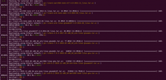
The mirror website of the cross compilation toolchain in China is the open source software mirror site of Tsinghua University
https://mirrors.tuna.tsinghua.edu.cn/armbian-releases/_toolchain/
After downloading toolchains, multiple versions of cross compilation toolchains will be included, and the development board will only use two of them
test@test:~/orangepi-build$ ls toolchains/
gcc-arm-11.2-2022.02-x86_64-aarch64-none-linux-gnu
gcc-arm-11.2-2022.02-x86_64-arm-none-linux-gnueabihf
gcc-arm-9.2-2019.12-x86_64-aarch64-none-linux-gnu
gcc-arm-9.2-2019.12-x86_64-arm-none-linux-gnueabihf
gcc-linaro-4.9.4-2017.01-x86_64_arm-linux-gnueabi
gcc-linaro-5.5.0-2017.10-x86_64_arm-linux-gnueabihf
gcc-linaro-7.4.1-2019.02-x86_64_aarch64-linux-gnu
gcc-linaro-7.4.1-2019.02-x86_64_arm-linux-gnueabi
gcc-linaro-aarch64-none-elf-4.8-2013.11_linux
gcc-linaro-arm-linux-gnueabihf-4.8-2014.04_linux
gcc-linaro-arm-none-eabi-4.8-2014.04_linux
The cross compilation toolchain used to compile Linux kernel source code is
linux5.10和linux6.1
gcc-arm-11.2-2022.02-x86_64-aarch64-none-linux-gnu
The cross compilation toolchain used to compile the u-boot source code is
v2017.09
gcc-linaro-7.4.1-2019.02-x86_64_aarch64-linux-gnu

Explanation of the complete directory structure of orangepi build
After downloading the orangepi build repository, it does not include the Linux kernel, U-boot source code, or cross compilation toolchain. The Linux kernel and U-boot source code are stored in separate Git repositories
The Git repository where the Linux 5.10 kernel source code is stored is as follows:
https://github.com/orangepi-xunlong/linux-orangepi/tree/orange-pi-5.10-rk35xx
The Git repository where the Linux 6.1 kernel source code is stored is as follows:
https://github.com/orangepi-xunlong/linux-orangepi/tree/orange-pi-6.1-rk35xx
The git repository where the u-boot source code is stored is as follows:
https://github.com/orangepi-xunlong/u-boot-orangepi/tree/v2017.09-rk3588
When Orangepi build is first run, it will download the cross compilation toolchain, u-boot, and Linux kernel source code. After successfully compiling the Linux image once, the files and folders that can be seen in Orangepi build are:
build.sh: Compile startup script
external: Contains configuration files required for compiling the image, scripts for specific functions, and source code for some programs. The rootfs compressed file cached during the image compilation process is also stored in the external file
kernel: Store the source code of the Linux kernel. The folder named orange-pi-5.10-rk35xx contains the kernel source code of the legacy branch of the RK3588/RK3588S series development board, while the folder named orange-pi-6.1-rk35xx contains the kernel source code of the current branch of the RK3588/RK3588S series development board. Please do not manually modify the name of the kernel source code folder. If modified, the compilation system will re download the kernel source code when running
LICENSE: GPL 2 License File
README.md: Orangepi build documentation
output: Store compiled deb packages such as u-boot and Linux, compilation logs, and compiled images
scripts: General script for compiling Linux images
toolchains: Store cross compilation toolchain
u-boot: Store the source code of u-boot, and the folder named v2017.09-rk3588 contains the u-boot source code of the legacy branch of RK3588/RK3588S series development boards. Please do not manually modify the name of the u-boot source code folder. If it is modified, the compilation system will re download the u-boot source code when running
userpatches: Store the configuration files required for compiling scripts
test@test:~/orangepi-build$ ls
build.sh external kernel LICENSE output README.md scripts toolchains u-boot userpatches
Compiling u-boot
Run the build.sh script, remember to grant sudo privileges
test@test:~/orangepi-build$ sudo ./build.sh
Select U-boot package and press Enter
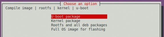
Next, select the model of the development board
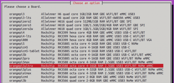
Then it will start compiling u-boot, and some of the information prompted during compilation is explained as follows
Version of u-boot source code
[ o.k. ] Compiling u-boot [ v2017.09 ]
Version of cross compilation toolchain
[ o.k. ] Compiler version [ aarch64-linux-gnu-gcc 7.4.1 ]
The path of the compiled u-boot deb package
[ o.k. ] Target directory [ orangepi-build/output/debs/u-boot ]
The package name of the compiled u-boot deb package
[ o.k. ] File name [ linux-u-boot-legacy-orangepi5ultra_1.0.2_arm64.deb ]
Compilation time used
[ o.k. ] Runtime [ 1 min ]
Repeat the command to compile u-boot, and use the following command to start compiling u-boot directly without selecting through the graphical interface
[ o.k. ] Repeat Build Options [ sudo ./build.sh BOARD=orangepi5ultra BRANCH=legacy BUILD_OPT=u-boot KERNEL_CONFIGURE=no ]
View the compiled u-boot deb package
test@test:~/orangepi-build$ ls output/debs/u-boot/
linux-u-boot-legacy-orangepi5ultra_1.0.2_arm64.deb
The generated deb package of u-boot contains the following files
Use the following command to decompress the deb package
test@test:~/orangepi-build$ cd output/debs/u-boot
test@test:~/orangepi_build/output/debs/u-boot$ $ dpkg -x \
linux-u-boot-legacy-orangepi5ultra_1.0.2_arm64.deb . (Please note that there is a '.' at the end of the command)
test@test:~/orangepi_build/output/debs/u-boot$ ls
linux-u-boot-legacy-orangepi5ultra_1.0.2_arm64.deb usr
The decompressed file is shown below
test@test:~/orangepi-build/output/debs/u-boot$ tree usr
usr
└── lib
├── linux-u-boot-legacy-orangepi5ultra_1.0.2_arm64
│ ├── idbloader.img
│ ├── rkspi_loader.img
│ └── u-boot.itb
└── u-boot
├── LICENSE
├── orangepi_5_ultra_defconfig
└── platform_install.sh
3 directories, 6 files
When the orangepi build compilation system compiles the u-boot source code, it first synchronizes the u-boot source code with the u-boot source code on the GitHub server. Therefore, if you want to modify the u-boot source code, you first need to turn off the download and update function of the source code (you need to compile the u-boot completely before turning off this function, otherwise it will prompt that the u-boot source code cannot be found. If it is a compressed source code downloaded from Baidu Cloud Drive, there is no problem because the u-boot source code is already cached). Otherwise, the modifications made will be restored. The method is as follows:
Set the IGNOREUPDATES variable to "yes" in userpatches/config-default.conf
test@test:~/orangepi-build$ vim userpatches/config-default.conf
IGNORE_UPDATES="yes"
When debugging u-boot code, you can use the following method to update u-boot in the Linux image for testing
Upload the compiled deb package of u-boot to the Linux system of the development board
test@test:~/orangepi-build$ cd output/debs/u-boot
test@test:~/orangepi_build/output/debs/u-boot$ scp \
linux-u-boot-legacy-orangepi5ultra_1.0.2_arm64.deb root@192.168.1.xxx:/root
Then log in to the development board and uninstall the deb package of the installed u-boot
root@orangepi:~# apt purge -y linux-u-boot-orangepi5ultra-legacy
Reinstall the newly uploaded deb package for u-boot
root@orangepi:~# dpkg -i linux-u-boot-legacy-orangepi5ultra_1.0.2_arm64.deb
Then run the nand sata install script
root@orangepi:~# nand-sata-install
Then select 5 Install/Update the bootloader on SD/eMM to update u-boot in TF card or 7 Install/Update the bootloader on SPI Flash to update u-boot in SPI Flash
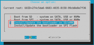
After pressing the enter key, a warning will first pop up
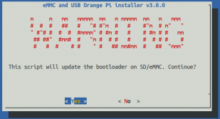
Pressing the enter key again will start updating u-boot, and after the update is complete, the following information will be displayed
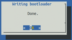
Then you can restart the development board to test whether the u-boot modifications have taken effect
Other useful information
In the u-boot 2017.09 source code, the defconfig configuration file used by the development board is
orangepi-build/u-boot/v2017.09-rk3588/configs/orangepi_5_ultra_defconfigIn the U-boot 2017.09 source code, the dts file used for the development board is


orangepi-build/u-boot/v2017.09-rk3588/arch/arm/dts/rk3588-orangepi-5-ultra.dtsCompiling Linux Kernel
Run the build.sh script, remember to grant sudo privileges
test@test:~/orangepi-build$ sudo ./build.sh
Select Kernel package and press Enter
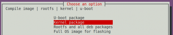
Next, select the model of the development board
Then it will prompt whether the kernel configuration interface needs to be displayed. If the kernel configuration does not need to be modified, select the first one. If the kernel configuration needs to be modified, select the second one
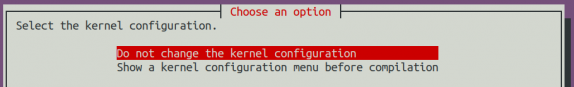
If step 4) selects the option to display the kernel configuration menu (second option), a kernel configuration interface opened through make menuconfig will pop up. At this time, you can directly modify the kernel configuration, save and exit after modification, and then start compiling the kernel source code
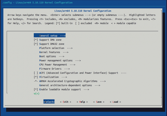


If there is no need to modify the configuration options of the kernel, passing KERNEL_CONFIGURE=no when running the build.sh script can temporarily block the pop-up kernel configuration interface
test@test:~/orangepi-build$ sudo ./build.sh KERNEL_CONFIGURE=no
You can also set KERNEL_CONFIGURE=no in the orangepi-build/userpatches/config-default.conf default.exe configuration file to permanently disable this feature
If the following error appears when compiling the kernel, it is due to the small terminal interface of Ubuntu PC, which causes the make menuconfig interface to not display. Please set the terminal of Ubuntu PC to its maximum size and run the build.sh script again


The following is a partial explanation of the information prompted when compiling kernel source code
Version of Linux kernel source code
[ o.k. ] Compiling current kernel [ 5.10.160 ]
The version of the cross compilation toolchain used
[ o.k. ] Compiler version [ aarch64-none-linux-gnu-gcc 11.2.1 ]
The default configuration file used by the kernel and the path where it is stored
[ o.k. ] Using kernel config file [ config/kernel/linux-rockchip-rk3588-legacy.config ]
The path of the compiled kernel related deb package
[ o.k. ] Target directory [ orangepi-build/output/debs/ ]
The package name of the compiled kernel image deb package
[ o.k. ] File name [ linux-image-legacy-rockchip-rk3588_1.0.2_arm64.deb ]
Compilation time used
[ o.k. ] Runtime [ 5 min ]
Finally, the compilation command for the kernel selected last time will be displayed. The following command can be used to start compiling the kernel source code without selecting it through the graphical interface
[ o.k. ] Repeat Build Options [ sudo ./build.sh BOARD=orangepi5ultra BRANCH=legacy BUILD_OPT=kernel KERNEL_CONFIGURE=no ]
View the compiled kernel related deb packages
linux-dtb-legacy-rockchip-rk3588_1.0.2_arm64.deb Contains dtb files used by the kernel
linux-headers-legacy-rockchip-rk3588_1.0.2_arm64.deb Contains kernel header files
linux-image-legacy-rockchip-rk3588_1.0.2_arm64.deb Contains kernel images and kernel modules
test@test:~/orangepi-build$ ls output/debs/linux-*
output/debs/linux-dtb-legacy-rockchip-rk3588_1.0.2_arm64.deb output/debs/linux-image-legacy-rockchip-rk3588_1.0.2_arm64.deb
output/debs/linux-headers-legacy-rockchip-rk3588_1.0.2_arm64.deb
The deb package of the generated Linux image contains the following files
Use the following command to decompress the deb package
test@test:~/orangepi-build$ cd output/debs
test@test:~/orangepi_build/output/debs$ mkdir test
test@test:~/orangepi_build/output/debs$ cp \
linux-image-legacy-rockchip-rk3588_1.0.2_arm64.deb test/
test@test:~/orangepi_build/output/debs$ cd test
test@test:~/orangepi_build/output/debs/test$ dpkg -x \
linux-image-legacy-rockchip-rk3588_1.0.2_arm64.deb .
test@test:~/orangepi_build/output/debs/test$ ls
boot etc lib linux-image-legacy-rockchip-rk3588_1.0.2_arm64.deb usr
The decompressed file is shown below
test@test:~/orangepi-build/output/debs/test$ tree -L 2
.
├── boot
│ ├── config-5.10.160-rockchip-rk3588
│ ├── System.map-5.10.160-rockchip-rk3588
│ └── vmlinuz-5.10.160-rockchip-rk3588
├── etc
│ └── kernel
├── lib
│ └── modules
├── linux-image-legacy-rockchip-rk3588_1.0.2_arm64.deb
└── usr
├── lib
└── share
When the Orangepi build compilation system compiles the Linux kernel source code, it first synchronizes the Linux kernel source code with the GitHub server's Linux kernel source code. Therefore, if you want to modify the Linux kernel source code, you first need to turn off the source code update function (you need to compile the Linux kernel source code completely before turning off this function, otherwise it will prompt that the Linux kernel source code cannot be found. If it is a source code compressed package downloaded from Baidu Cloud Drive, there is no problem because the Linux source code is already cached). Otherwise, the modifications made will be restored. The method is as follows:
Set the IGNOREUPDATES variable to "yes" in userpatches/config-default.conf
test@test:~/orangepi-build$ vim userpatches/config-default.conf
IGNORE_UPDATES="yes"
If modifications have been made to the kernel, the following method can be used to update the kernel and kernel modules of the Linux system on the development board
Upload the compiled deb package of the Linux kernel to the Linux system on the development board
test@test:~/orangepi-build$ cd output/debs
test@test:~/orangepi-build/output/debs$ scp \
linux-image-legacy-rockchip-rk3588_1.0.2_arm64.deb root@192.168.1.xxx:/root
Then log in to the development board and uninstall the deb package of the installed Linux kernel
root@orangepi:~# apt purge -y linux-image-legacy-rockchip-rk3588
Reinstall the deb package of the new Linux kernel that was just uploaded
root@orangepi:~# dpkg -i linux-image-legacy-rockchip-rk3588_1.0.2_arm64.deb
Then restart the development board and check if the kernel related modifications have taken effect
root@orangepi:~# reboot
Compile rootfs
Run the build.sh script, remember to grant sudo privileges
test@test:~/orangepi-build$ sudo ./build.sh
Select Rootfs and all deb packages, then press enter

Next, select the model of the development board
Then select the type of rootfs
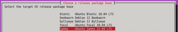
Then select the type of image
Image with console interface (server) Represents a server version image with a relatively small size
Image with desktop environment Represents a desktop image with a relatively large volume

If you are compiling the server version image, you can also choose to compile the Standard version or the Minimal version. The Minimal version comes with much less pre installed software than the Standard version (please do not choose the Minimal version unless you have special requirements, as many things are not pre installed by default and some features may not be available)

If compiling a desktop version of the image, you also need to choose the type of desktop environment. Currently, Ubuntu Jammy mainly maintains XFCE and Gnome desktops, Ubuntu Focal only maintains XFCE desktops, Debian Bullseye mainly maintains XFCE and KDE desktops, and Debian Bookwork mainly maintains XFCE desktops


Then you can choose additional software packages that need to be installed. Please press the enter key here to skip directly.
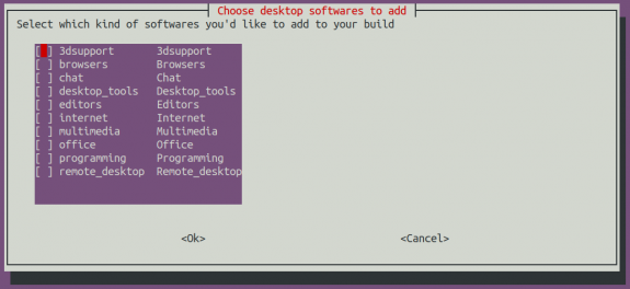
Then it will start compiling rootfs, and some of the information prompted during compilation is as follows
Types of rootfs
[ o.k. ] local not found [ Creating new rootfs cache for jammy]
The storage path of the rootfs compressed file generated by compilation
[ o.k. ] Target directory [ external/cache/rootfs ]
The name of the rootfs compressed file generated by compilation
[ o.k. ] File name [ jammy-xfce-arm64.f930ff6ebbac1a72108a2e100762b18f.tar.lz4 ]
Compilation time used
[ o.k. ] Runtime [ 13 min ]
View the compiled rootfs compressed file
- jammy-xfce-arm64.f930ff6ebbac1a72108a2e100762b18f.tar.lz4 is a compressed file of rootfs, and the meaning of each field in the name is


jammy represents the type of Linux distribution of rootfs
b) xfce represents rootfs as the desktop version type, and if it is cli, it represents the server version type
c) arm64 represents the architecture type of rootfs
d) f930ff6ebbac1a72108a2e100762b18f is an MD5 hash value generated from the package names of all software packages installed by rootfs. As long as the list of software packages installed by rootfs is not modified, this value will not change. The compilation script will use this MD5 hash value to determine whether to recompile rootfs
jammy-xfce-arm64.f930ff6ebbac1a72108a2e100762b18f.tar.lz4.list lists the package names of all the software packages installed by rootfs
test@test:~/orangepi-build$ ls external/cache/rootfs/
jammy-xfce-arm64.f930ff6ebbac1a72108a2e100762b18f.tar.lz4
jammy-xfce-arm64.f930ff6ebbac1a72108a2e100762b18f.tar.lz4.current
jammy-xfce-arm64.f930ff6ebbac1a72108a2e100762b18f.tar.lz4.list
- If the required rootfs already exist in external/cache/rootfs, compiling rootfs again will skip the compilation process and will not restart. When compiling the image, it will also search for available rootfs in external/cache/rootfs, and if so, use them directly, which can save a lot of download and compilation time.
Compiling Linux Images
Run the build.sh script, remember to grant sudo privileges
test@test:~/orangepi-build$ sudo ./build.sh
Select Full OS image for flashing and press Enter

Then select the model of the development board
Then select the type of rootfs
Then select the type of image
Image with console interface (server) Represents a server version image with a relatively small size
Image with desktop environment Represents a desktop image with a relatively large volume
If you are compiling the server version image, you can also choose to compile the Standard version or the Minimal version. The Minimal version comes with much less pre installed software than the Standard version (please do not choose the Minimal version unless you have special requirements, as many things are not pre installed by default and some features may not be available)
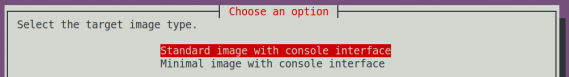
If compiling a desktop version of the image, you also need to choose the type of desktop environment. Currently, Ubuntu Jammy mainly maintains XFCE and Gnome desktops, Ubuntu Focal only maintains XFCE desktops, Debian Bullseye mainly maintains XFCE and KDE desktops, and Debian Bookwork mainly maintains XFCE desktops
Then you can choose additional software packages that need to be installed. Please press the enter key here to skip directly.
Then it will start compiling the Linux image, and the general process of compilation is as follows
a. Initialize the compilation environment of Ubuntu PC and install the necessary software packages for the compilation process
b. Download the source code for u-boot and Linux kernel (if cached, only update the code)
c. Compile the u-boot source code and generate the deb package for u-boot
d. Compile Linux source code and generate deb packages related to Linux
e. Creating a deb package for Linux firmware
f. Create a deb package for the orangepi config tool
g. Create deb packages that support board level support
h. If compiling the desktop version image, desktop related deb packages will also be created
i. Check if rootfs have been cached. If not, create a new rootfs. If cached, decompress and use it directly
j. Install the deb package generated earlier into rootfs
k. Make specific settings for different development boards and types of images, such as pre installing additional software packages, modifying system configurations, etc
l. Then create an image file and format the partition, with the default type being ext4
m. Copy the configured rootfs to the partition of the image again
n. Then update initramfs
o. Finally, write the bin file of u-boot to the image using the dd command
After compiling the image, the following message will be prompted
The storage path of the compiled image
[ o.k. ] Done building [ output/images/orangepi5ultra_1.0.2_debian_bullseye_desktop_xfce_linux5.10.160/orangepi5ultra_1.0.2_debian_bullseye_desktop_xfce_linux5.10.160.img ]
Compilation time used
[ o.k. ] Runtime [ 19 min ]
The command to repeatedly compile the image can be used to start compiling the image without selecting through the graphical interface
[ o.k. ] Repeat Build Options [ sudo ./build.sh BOARD=orangepi5ultra BRANCH=legacy BUILD_OPT=image RELEASE=bullseye BUILD_MINIMAL=no BUILD_DESKTOP=no KERNEL_CONFIGURE=yes ]
Instructions for using Android 13 system
Supported Android versions
| Android version | Kernel version |
| Android 13 | Linux5.10 |
Adaptation of Android Features
| function | Android 13 |
| HDMI TX Video | OK |
| HDMI TX Audio | OK |
| HDMI RX Video | OK |
| HDMI RX Audio | OK |
| USB2.0x2 | OK |
| USB3.0x2 | OK |
| 2.5G Ethernet port | OK |
| Network port status light | OK |
| WIFI | OK |
| Bluetooth | OK |
| Debug UART | OK |
| RTC chip | OK |
| FAN fan interface | OK |
| EMMC extension interface | OK |
| GPIO(40pin) | OK |
| UART(40pin) | OK |
| SPI(40pin) | OK |
| I2C(40pin) | OK |
| PWM(40pin) | OK |
| TF card startup | OK |
| OV13850 camera | OK |
| OV13855 camera | OK |
| SPI+NVME startup | OK |
| LCD | OK |
| MIC | OK |
| Headphone playback | OK |
| Earphone recording | OK |
| Tri color LED light | OK |
| GPU | OK |
| NPU | OK |
| VPU | OK |
| Power on/off button | OK |
WIFI connection testing method
First, hold down the left mouse button on the desktop and drag up to open the application list.
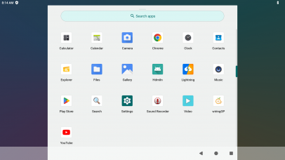
Then open Setting。


- Then select the Internet option in Network & internet.

- Then turn on the Wi-Fi switch.

If everything is normal after turning on Wi-Fi, you can scan nearby Wi-Fi hotspots.
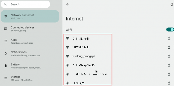
Then select the Wi Fi you want to connect to, and the password input interface shown in the following figure will pop up.
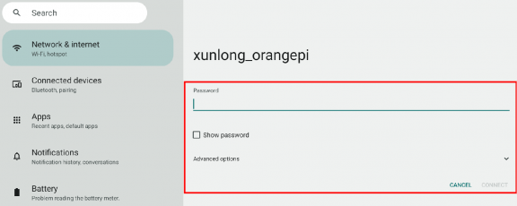
Then use the keyboard to enter the password corresponding to Wi-Fi, and click CONNECT with the mouse to start connecting to Wi-Fi.

The display after successful Wi-Fi connection is shown in the following figure:


Bluetooth testing method
First, hold down the left mouse button on the desktop and drag up to open the application list.
Then enter Setting。

Then select Connected devices。
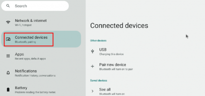
Then click Pair new device to turn on Bluetooth and start scanning for surrounding Bluetooth devices.
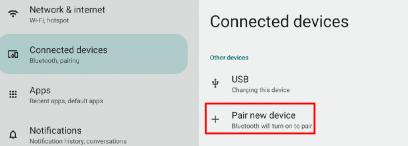
The Bluetooth devices found will be displayed under Available devices.
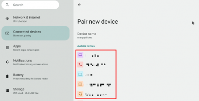
Then click on the Bluetooth device you want to connect to start pairing. When the interface below pops up, please use the mouse to select the Pair option.

The test here is the configuration process of the development board and Android phone Bluetooth. At this time, the confirmation interface below will pop up on the phone, and clicking the pairing button on the phone will start the pairing process.
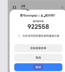
After pairing, you can see the paired Bluetooth device as shown in the following figure.

At this point, you can use your phone's Bluetooth to send an image to the development board. After sending, you can see the confirmation interface below in the Android system of the development board, and then click Accept to start receiving the image sent by your phone.

The images received by the Android system Bluetooth on the development board can be viewed by opening the Download directory in the file manager.


10.1 inch MIPI screen usage method
Firstly, the screen needs to be assembled. Please refer to the assembly method for a 10.1-inch MIPI screen.
The position of the mipi LCD screen interface on the development board is shown in the following figure:
Connect the assembled screen to the LCD interface of the development board, connect the Type-C power supply to the board, and power it on. After the system starts up, you can see the screen display as shown in the following figure:
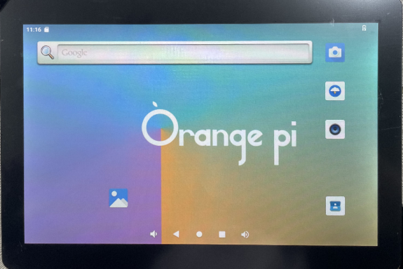

Testing Method for OV13850 and OV13855 MIPI Cameras
At present, the development board supports two MIPI cameras, OV13850 and OV13855. The specific images are shown below:
OV13850 camera with 13 million MIPI interface

OV13855 camera with 13 million MIPI interface

The adapter board and FPC cable used for OV13850 and OV13855 cameras are the same, except that the two cameras are connected to the adapter board at different positions. The FPC cable is shown in the following figure. Please note that the FPC cable has a direction. The end marked as TO MB needs to be plugged into the camera interface of the development board, and the end marked as TO CAMERA needs to be plugged into the camera adapter board.
There are a total of 3 camera interfaces on the camera adapter board, and only one can be connected for use at a time, as shown in the following figure. Among them:
Connect interface 1 to OV13850 camera
Connect interface 2 to OV13855 camera
Interface 3 is not in use, just ignore it

There are a total of 3 camera interfaces on the Orange Pi 5 Ultra development board. In the Android system, only Cam0 and Cam1 are enabled by default. We define the positions of Cam0, Cam1, and Cam2 as shown in the following figure:
The method of inserting the camera into the Cam0 interface of the development board is as follows:
The method of inserting the camera into the Cam1 interface of the development board is as follows:
After connecting the camera to the development board, we can use the following method to test the camera:
First, hold down the left mouse button on the desktop and drag up to open the application list.
Then open the camera app.

Then you can see the preview screen of the camera.
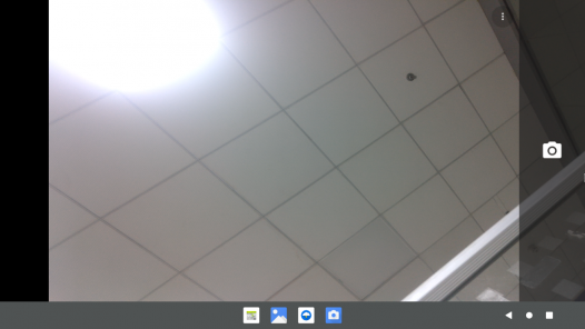
In addition to a single camera, we can also connect two cameras simultaneously. After connecting the dual cameras, as in the previous steps, open the camera app to see the image of one of the cameras.
The method to switch to another camera is:


First, click on these three points in the upper right corner.
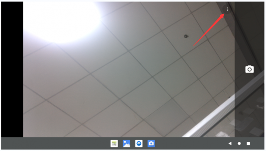
Then click on the position shown in the picture to switch cameras.

Press and hold the mouse in the area shown in the red box in the camera app, and then drag it to the right to bring up the switch interface between taking photos and filming.
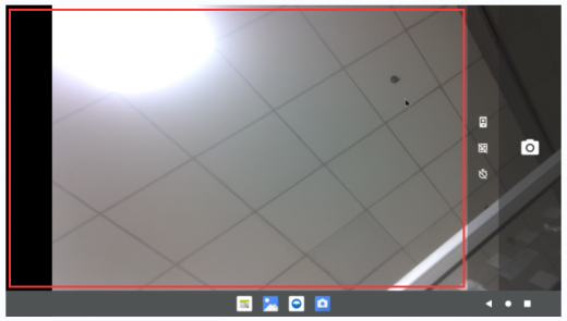
The interface for switching between photography and videography is shown below. Click on Video to switch to recording mode.
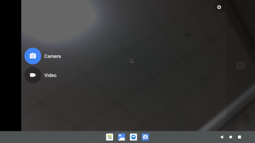


40pin interface GPIO, UART, SPI, and PWM testing
40pin GPIO port test
First, hold down the left mouse button on the desktop and drag up to open the application list.
Then open the WiringoP app.

The main interface of WiringOP is shown in the following figure, and then click the GPIO_TEST button to open the GPIO testing interface.
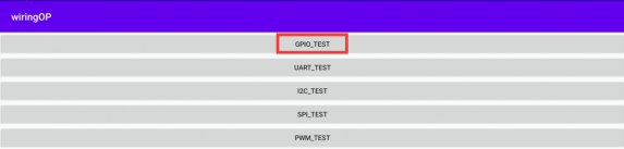
The GPIO testing interface is shown in the following figure, where the two rows of CheckBox buttons on the left correspond one-to-one with the 40 pin pins. When the CheckBox button is selected, the corresponding GPIO pin will be set to OUT mode and the pin level will be set to high level; When unchecked, the GPIO pin level is set to low level; When clicking the GPIO READALL button on the right, information such as wPi number, GPIO mode, and pin level can be obtained;
When the BLINK ALL GPIO button is clicked, the program will control 28 GPIO ports to continuously switch between high and low levels.
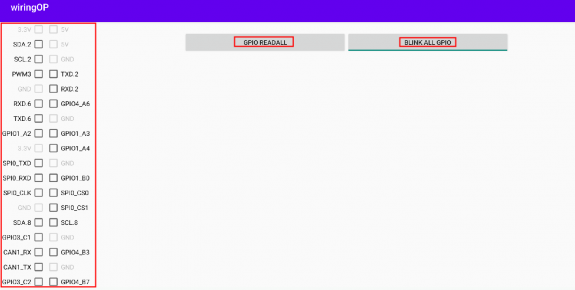
Click the GPIO READALL button to access detailed information for all pins, as shown in the following figure:
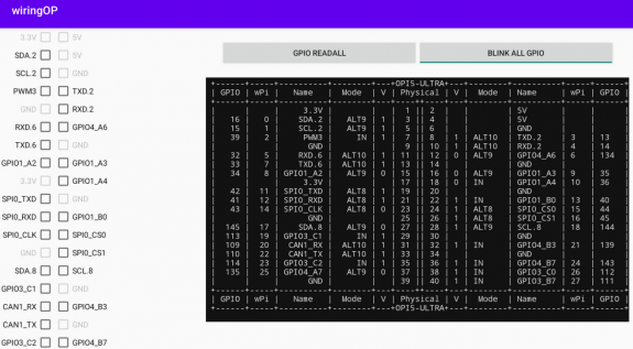
There are a total of 28 GPIO ports available in the 40 pin development board. Taking pin 7- corresponding to GPIO as GPO1_A7- corresponding to wPi serial number 2- as an example, we will demonstrate how to set the high and low levels of GPIO ports. Firstly, click on the CheckBox button corresponding to pin 7. When the button is selected, pin 7 will be set to high level. After setting, you can use a multimeter to measure the voltage value of the pin. If it is 3.3v, it means that the high level has been successfully set.
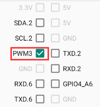
Then click the GPIO READALL button to see that the current mode of pin 7 is OUT and the pin level is high.
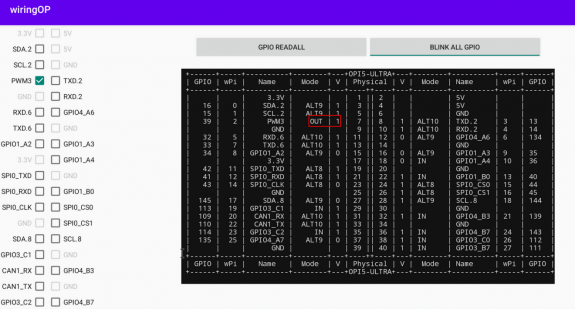
Click the CheckBox button in the following image again to uncheck the status. Pin 7 will be set to a low level. After setting, you can use a multimeter to measure the voltage value of the pin. If it is 0v, it means that the low level has been successfully set
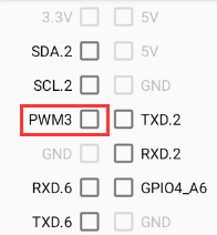
Then click the GPIO READALL button to see that the current mode of pin 7 is OUT and the pin level is low.
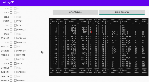


40pin UART Test
- In the Android system, two serial ports, UART3 and UART6, are enabled by default. The corresponding pins in the 40 pin configuration are shown in the table below, and the corresponding device nodes are/dev/ttyS3 and/dev/ttyS6.
| UART bus | RX corresponds to 40 pins | TX corresponds to 40 pins |
| UART3 | Pin 33 | Pin 31 |
| UART6 | Pin 11 | Pin 13 |
First, hold down the left mouse button on the desktop and drag up to open the application list.
Then open the WiringoP app.
The main interface of WiringoP APP is shown in the following figure, and then click the UART_TEST button to open the UART test interface.
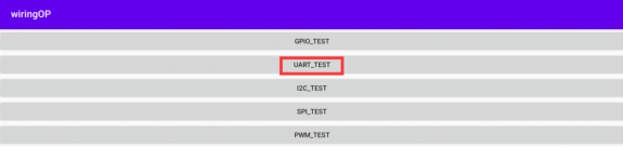
The serial port testing interface of WiringOP APP is shown in the following figure:


- Next, enter the desired baud rate in the editing box, and then click the OPEN button to open the/dev/ttyS3 node. After successful opening, the OPEN button will become unselectable, while the CLOSE and SEND buttons will become selectable.

- Then use DuPont wire to short-circuit the RXD and TXD pins of UART
- Then you can enter a character in the send edit box below and click the SEND button to start sending.

- If everything is normal, the received string will be displayed in the receiving box.

40pin SPI test
The SPI0 group of SPI buses is enabled by default in Android.
Here, the w25q64 module is used to test the SPI interface. First, connect the w25q64 device to the SPI0 interface.
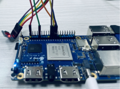
First, hold down the left mouse button on the desktop and drag up to open the application list.
Then open the WiringoP app.
The main interface of WiringOP APP is displayed as shown in the following figure. Click the SPI_TEST button to open the SPI testing interface.
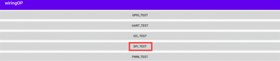
Then click the OPEN button to initialize SPI.


Then fill in the bytes that need to be sent, such as reading the ID information of w25q64, filling in the address 0x9f in data [0], and then clicking the TRANSFER button.
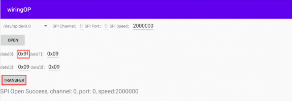
Finally, the app will display the read ID information.


The MANUFACTURER ID of the w25q64 module is EFh, and the Device ID is 4017h, which corresponds to the values read above (h represents hexadecimal).
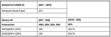

40 pin PWM test
- Android has enabled PWM3 and PWM14 by default, and the corresponding pins are located at the 40pin position as shown in the following figure:
| PWM bus | Corresponding to 40 pins |
| PWM3 | Pin 7 |
| PWM14 | 35 |
First, hold down the left mouse button on the desktop and drag up to open the application list.
Then open the WiringoP app.
Then click the PWM_TEST button on the main interface of WirgOP to enter the PWM testing interface.
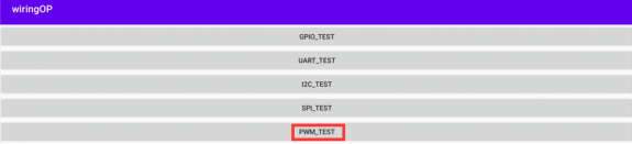
The base address of PWM3 is fe8b0030, and the base address of PWM14 is febf0020. Here, fe8b0030.pwm is displayed on the right side of pwmchip0, indicating that PWM3 has been selected.

Then confirm the PWM channel, which defaults to channel 0, and confirm the PWM cycle. The default configuration is 50000ns, and the converted PWM frequency is 20KHz, which can be modified by clicking the EXPORT button to export PWM3.
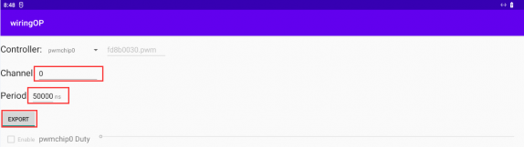
Then drag the drag bar below to change the PWM duty cycle, and select Enable to output the PWM waveform.


- Then use an oscilloscope to measure pin 7 of the 40 pins on the development board to see the waveform below.

Usage of ADB
Method for Switching USB OTG Mode
The development board has 4 USB interfaces, among which the USB interface marked in red in the figure can support both Host mode and Device mode, while the other 3 USB interfaces only support Host mode.

The USB OTG interface defaults to Host mode and can be used to connect USB devices such as mice and keyboards. If you want to use ADB, you need to manually switch to Device mode.
First, hold down the left mouse button on the desktop and drag up to open the application list.
Then open Settings。

Then select About tablet。
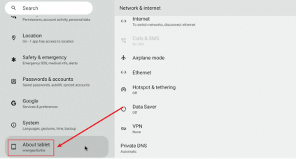
Then click the Build number menu bar multiple times with the mouse until You are now a developer! The prompt.
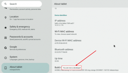
Then click to return to the previous menu and select System.
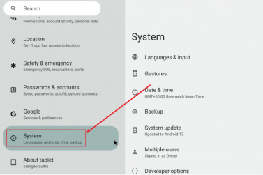
Then select Developer options。

Finally, locate the USB OTG Mode Switch switch, turn it on to switch to Device mode, and turn it off to switch to Host mode.


Using a data cable to connect adb for debugging
Firstly, prepare a high-quality USB 2.0 male to male data cable.

Then refer to the method of switching USB OTG mode to switch USB OTG to device mode.
Then use a USB 2.0 male to female data cable to connect the development board to the USB interface of the computer (please also use a TypeC power supply to power the development board).
Install adb tools on Ubuntu PC.
test@test:~$ sudo apt update
test@test:~$ sudo apt -y install adb
The recognized ADB devices can be viewed through the following command.
test@test:~$ adb devices
List of devices attached
S63QCF54CJ device
test@test:~$ lsusb
Bus 003 Device 006: ID 2207:0006
Then you can log in to the Android system through adb shell on Ubuntu PC.
test@test:~$ adb shell
console:/ $
- Execute the command to remount the Android system.
test@test:~$ adb root
test@test:~$ adb remount
- Then you can transfer the file to the Android system.
test@test:~$ adb push example.txt /system/
Debugging with network connection adb
Using network adb does not require a USB Typc C interface data cable to connect the computer and development board, but communicates through the network. Therefore, first make sure that the wired or wireless network of the development board is connected, and then obtain the IP address of the development board, which will be used later.
Ensure that the service.adb.tcp.port of the Android system is set to port number 5555.
console:/ # getprop | grep "adb.tcp"
[service.adb.tcp.port]: [5555]
If service.adb.tcp.port is not set, you can use the following command to set the port number of the network adb.
console:/ # setprop service.adb.tcp.port 5555
console:/ # stop adbd
console:/ # start adbd
Install adb tools on Ubuntu PC.
test@test:~$ sudo apt update
test@test:~$ sudo apt install -y adb
Then connect the network adb on Ubuntu PC.
test@test:~$ adb connect 192.168.1.xxx (The IP address needs to be changed to the IP address of the development board)
* daemon not running; starting now at tcp:5037
* daemon started successfully
connected to 192.168.1.xxx:5555
test@test:~$ adb devices
List of devices attached
192.168.1.xxx:5555 device
Then you can log in to the Android system through the adb shell on an Ubuntu PC.
test@test:~$ adb shell
console:/ #
Testing Method for HDMI RX
The location of the HDMI RX interface on the development board is as follows:
Then use the HDMI to HDMI cable shown in the figure below to connect the HDMI output of other devices to the HDMI RX interface of the development board.
Ensure that the HDMI output of the device connected to the HDMI RX interface is normal, then hold down the left mouse button on the desktop and drag up to open the application list.
Then open the HDMI In test app.

Then you can see the video input of the HDMI RX (in the picture below, the HDMI RX displays the image of the HDMI output of the Opi5 development board, and a video is currently being played). At the same time, the audio input of the HDMI RX will also be output from the HDMI TX interface or headphone interface of the development board.


Compilation method of Android 13 source code
Download the source code of Android 13
Firstly, download the compressed Android 13 source code from Baidu Cloud Drive or Google Cloud Drive.
After downloading the compressed Android 13 source code, please check if the MD5 checksum is correct. If it is not correct, please download the source code again.
test@test:~$ md5sum -c md5sum
Android_13.tar.gz00: OK
Android_13.tar.gz01: OK
Android_13.tar.gz02: OK
Android_13.tar.gz03: OK
Android_13.tar.gz04: OK
Android_13.tar.gz05: OK
Android_13.tar.gz06: OK
Android_13.tar.gz07: OK
Android_13.tar.gz08: OK
Then multiple compressed files need to be merged into one and decompressed.
test@test:~$ cat Android_13.tar.gz0* | tar -xvzf -
Compile the source code for Android 13
First, install and compile the software packages required for Android 13 source code.
test@test:~$ sudo apt-get update
test@test:~$ sudo apt-get install -y git gnupg flex bison gperf build-essential \
zip curl zlib1g-dev gcc-multilib g++-multilib libc6-dev-i386 \
lib32ncurses5-dev x11proto-core-dev libx11-dev lib32z1-dev ccache \
libgl1-mesa-dev libxml2-utils xsltproc unzip
test@test:~$ sudo apt-get install -y u-boot-tools
There is a make.sh compilation script in the source code, with the following compilation parameters:
-B:Compile uboot
-K:Compile kernel
-a: Compile android
-F:Compile uboot、kernel and android
-M:Generate partition images in the rockdev directory
-u:Package to generate a complete image that can ultimately be launched
-b:Specify the development board model
Compile uboot, kernel, and Android and package them into the final bootable complete image.
test@test:~$ cd Android_13
test@test:~/ Android_13$ ./make.sh -FMu -b orangepi5ultra --nvme --gapps
After compilation, the following information will be printed.
********rkImageMaker ver 2.1********
Generating new image, please wait...
Writing head info...
Writing boot file...
Writing firmware...
Generating MD5 data...
MD5 data generated successfully!
New image generated successfully!
Making update.img OK.
Make update image ok!
The final generated image file will be placed in the rockdev/Image-rk3588_t directory. Among them, update.img is the TF card boot image, and update_spi_nvme.img is the NVME SSD boot image.
test@test:~/Android_13$ cd rockdev/Image-rk3588_t
test@test:~/Android_13/rockdev/Image-rk3588_t$ ls update*
update.img update_spi_nvme.img
OpenWRT System User Manual
OpenWRT version
| OpenWRT version | Kernel version |
| v22.03.4 | Linux5.10.110 |
OpenWRT adaptation situation
| function | OpenWRT |
| USB2.0x2 | OK |
| USB3.0x2 | OK |
| 3 pin debugging serial port | OK |
| TF card startup | OK |
| 2.5G PCIe Ethernet port | OK |
| Network port status light | OK |
| LED light | OK |
| RTL8821CU USB network card | OK |
| RTL8723BU USB network card | OK |
| FAN fan interface | OK |
| EMMC extension interface | OK |
The first boot to expand rootfs
When starting the OpenWRT system for the first time, the resize-rootfs.sh script will be executed to expand rootfs, and it will automatically restart after the expansion is completed.
After logging into the system, you can use the df -h command to check the size of rootfs. If it matches the actual capacity of the storage device (TF card, eMMC, or NVME SSD), it indicates that the automatic expansion is running correctly.
root@OpenWrt:~# df -h
Filesystem Size Used Available Use% Mounted on
/dev/root 14.8G 14.7G 91.6M 99% /
tmpfs 495.5M 6.1M 489.4M 1% /tmp
tmpfs 512.0K 0 512.0K 0% /dev
/dev/root 14.8G 14.7G 91.6M 99% /opt/docker
Method of logging into the system
Login via serial port
Firstly, you can refer to the chapter on debugging serial port usage for instructions on how to use the serial port.
The OpenWrt system will automatically log in as the root user by default, and the display interface is shown below:
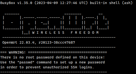

Login to the system via SSH
Please note that in the OpenWrt system of Orange Pi 5 Ultra, the network port is configured as a LAN port by default.
Firstly, connect the LAN port of the board to the network port of the computer using an Ethernet cable, so that the network port of the computer can obtain the IP address through DHCP.
The default LAN port IP of the board is set to 192.168.2.1, so the computer can obtain IP addresses starting with 192.168.2 at this time.
If the computer is installed with Ubuntu system, you can execute the following command to log in to the system through SSH. By default, you can log in directly without a password.
test@ubuntu:~$ ssh root@192.168.2.1
The display after successfully logging into the system is shown in the following figure:
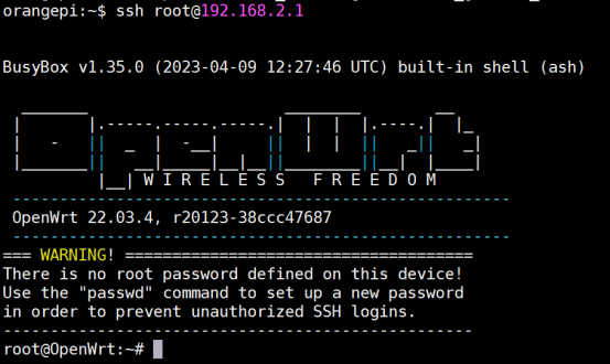
If the computer is installed with Windows system, you can refer to the method introduced in the section of SSH remote login development board under Windows to log in.

Login to LuCI Management Interface
Please note that in the OpenWrt system of Orange Pi 5 Ultra, the network port is configured as a LAN port by default.
- Firstly, connect the LAN port of the board to the network port of the computer using an Ethernet cable, so that the network port of the computer can obtain the IP address through DHCP.
- The default LAN port IP of the board is set to 192.168.2.1, so the computer can obtain IP addresses starting with 192.168.2 at this time.
- You can log in to the LuCI interface by entering the IP address 192.168.2.1 in the browser on your computer.

The OpenWrt system does not have a password set by default, so simply click the login button. After successful login, the interface will display as shown in the following figure:
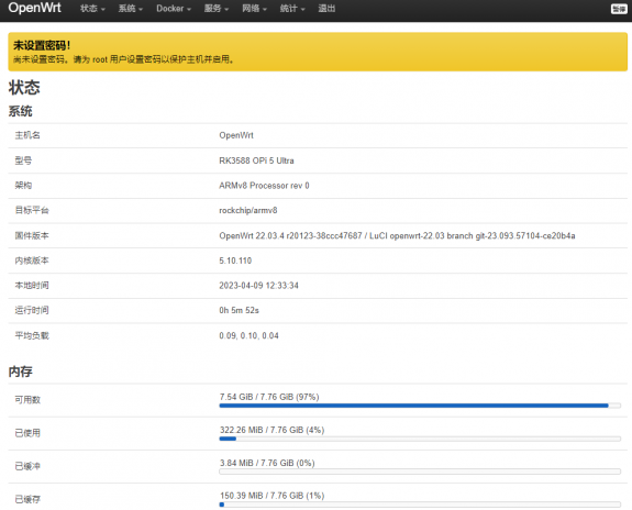

Log in to the terminal through the LuCI management interface
Please note that in the OpenWrt system of Orange Pi 5 Ultra, the network port is configured as a LAN port by default.
- Firstly, connect the LAN port of the board to the network port of the computer using an Ethernet cable, so that the network port of the computer can obtain the IP address through DHCP.
- The default LAN port IP of the board is set to 192.168.2.1, so the computer can obtain IP addresses starting with 192.168.2 at this time.
- You can log in to the LuCI interface by entering the IP address 192.168.2.1 in the browser on your computer.
- Select "Terminal" in the "Services" column of the navigation bar and click to enter.

At this point, the terminal interface is shown in the following figure:
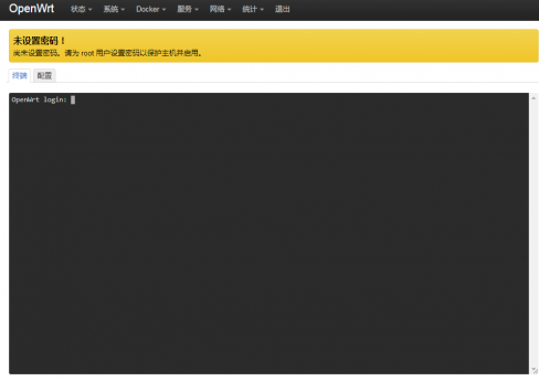
Enter the username root to log in
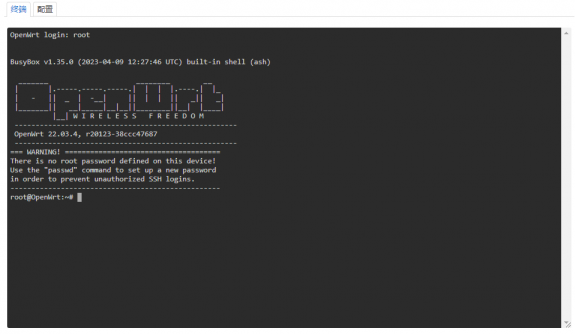


Login to the terminal using IP address and port number
Please note that in the OpenWrt system of Orange Pi 5 Ultra, the network port is configured as a LAN port by default.
- Firstly, connect the LAN port of the board to the network port of the computer using an Ethernet cable, so that the network port of the computer can obtain the IP address through DHCP.
- The default LAN port IP of the board is set to 192.168.2.1, so the computer can obtain IP addresses starting with 192.168.2 at this time.
- Then enter 192.168.2.1:7681 in the browser to log in to the OpenWRT terminal.

Method of modifying LAN port IP address through command line
- In the OpenWrt system, a command-line tool uci is provided, which can easily modify, add, delete, and read the contents of configuration files. For detailed instructions, please refer to the official documentation.
- First, use the following command to obtain the network configuration. The corresponding configuration file is/etc/config/network, and you can see that the value of the network.lan.ipaddr item is 192.168.2.1.
root@OpenWrt:~# uci show network
...
network.lan=interface
network.lan.device='br-lan'
network.lan.proto='static'
network.lan.ipaddr='192.168.2.1'
network.lan.netmask='255.255.255.0'
network.lan.ip6assign='60'
.…
- Then enter the following command to modify the network.lan.ipaddr option.
root@OpenWrt:~# uci set network.lan.ipaddr='192.168.100.1'
- Then enter the following command to complete the submission, which is written to the configuration file.
root@OpenWrt:~# uci commit
If the IP address in red font matches the one to be set, it indicates that the modification was successful.
root@OpenWrt:~# cat /etc/config/network
...
config interface 'lan'
option device 'br-lan'
option proto 'static'
option netmask '255.255.255.0'
option ip6assign '60'
option ipaddr '192.168.100.1'
...
- Restart the network through Ubuntu. Please refer to the official documentation for instructions on how to use Ubuntu.
root@OpenWrt:~# ubus call network restart
At this point, entering the command shows that the IP address of the LAN port is already 192.168.100.1.
root@OpenWrt:~# ifconfig br-lan
br-lan Link encap:Ethernet HWaddr FE:55:13:A3:EF:E7
inet addr:192.168.100.1 Bcast:192.168.100.255 Mask:255.255.255.0
inet6 addr: fd60:c4cd:1033::1/60 Scope:Global
UP BROADCAST MULTICAST MTU:1500 Metric:1
RX packets:0 errors:0 dropped:0 overruns:0 frame:0
TX packets:3 errors:0 dropped:0 overruns:0 carrier:0
collisions:0 txqueuelen:1000
RX bytes:0 (0.0 B) TX bytes:370 (370.0 B)
Method for changing root password
Modify via Command Line
- First, enter passwd root in the system command line, and the following prompt message will appear. At this time, you can enter the password you want to set and press Enter to confirm.
root@OpenWrt:/# passwd root
Enter new UNIX password:
- Next, you will be prompted to re-enter the password. At this point, enter the password again to confirm and press enter.
Retype password:
- The successfully modified display is as follows:
passwd: password for root changed by root
Modify through LuCI management interface
Firstly, refer to the login LuCI management interface to enter the OpenWRT management interface.
Then follow the steps below to change the password.
Find the "System" option in the navigation bar and click on it.
In the vertical bar options below the system, select "Management Rights" and click.
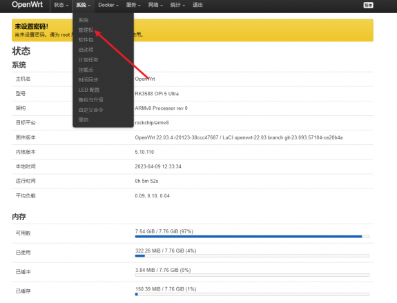
Select the 'Router Password' option on the tab page.
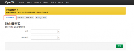
Modify and save the router password.
Enter the password you have set in the "Password" and "Confirm Password" dialog boxes (if unsure if the password is entered correctly, click the "*" icon behind the dialog box to display the input characters).
Click 'Save' to save the newly modified password.
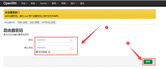


Note: In the "Password" and "Confirm Password" dialog boxes, the password entered twice needs to be consistent.
After the password is successfully changed, a pop-up box will appear saying "System password has been changed successfully". At this time, logging in to OpenWRT requires a password.
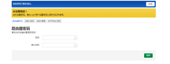

USB interface testing
Mounting USB storage devices at the command line
- First, insert the USB drive into the USB interface of the Orange Pi development board.
- If you can see the output of sdX by executing the following command, it means that the USB drive recognition is successful.
root@OpenWrt:~# cat /proc/partitions | grep "sd*"
major minor #blocks name
8 0 15126528 sda
- The mount command can be used to mount the USB drive to/mnt, and then you can view the files on the USB drive.
root@OpenWrt:~# mount /dev/sda /mnt/
root@OpenWrt:~# ls /mnt/
test.txt
- After mounting, you can use the df -h command to view the capacity usage and mounting point of the USB flash drive.
root@OpenWrt:~# df -h | grep "sd"
/dev/sda 14.4G 187.2M 14.2G 1% /mnt
Mounting USB storage devices on the LuCI management interface
Firstly, connect the USB flash drive (or other storage device) to the development board via USB 2.0.
Then follow the login LuCI management interface to enter the LuCI management interface.
Then, in the LuCI management interface, click on "System ->Mount Point" to enter the mount point configuration interface.
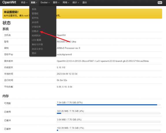
Then follow the steps below to add a mount point.
Find 'Mount Point' at the bottom of the global settings interface for mount points.
Below the mounting point, select the "Add" button and click to enter.


Next, a pop-up window will appear below.

Then you can start mounting the storage device.
Check 'Enabled'.
Select the actual connected device/dev/sda in the UUID column of the general settings (choose according to your own device).
Select "Custom" in the mount point column and fill in the target directory to be mounted to. Taking the/mnt directory as an example, enter to confirm.
Then click the "Save" button in the bottom right corner.


- Then you will return to the mount point global settings page and click "Save and Apply" in the bottom left corner of the page to make the mount point effective.

- After saving, you can see in the 'Mounted File System' that the storage device has been successfully mounted.

USB Wireless Network Card Test
The currently tested USB wireless network cards that can be used are shown below. For other models of USB wireless network cards, please test them yourself. If they cannot be used, you need to port the corresponding USB wireless network card driver.
| Serial number | model | |
| 1 | RTL8723BU
support 2.4G WIFI+BT4.0 |
File:Orange Pi 5 Ultra-image2 52.png |
| 2 | RTL8821CU
support 2.4G +5G WIFI support BT 4.2 |
Method of using a USB wireless network card to connect to a WIFI hotspot
Insert the USB wireless network card into the USB port of the development board, and then connect the power supply to power on the development board.
After the system startup is complete, click on Network ->Wireless to enter the wireless WiFi configuration interface.
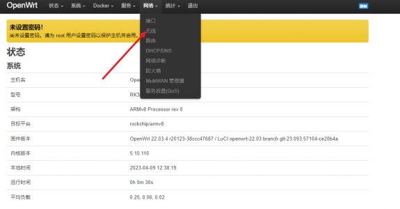
The default wireless configuration of OpenWRT system is Master mode. For the convenience of the next operation, we will remove the default wireless connection.

Then click on the bottom right corner of the page to save and make the configuration effective.

Then click the scan button to scan the surrounding WiFi hotspots.
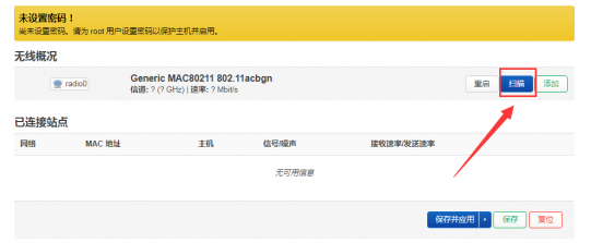
Then a window will pop up displaying available WiFi hotspots. Click the "Join Network" button to the right of the desired WiFi hotspot to connect.
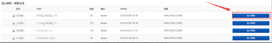
Then a interface will pop up to connect to the WiFi hotspot. We will enter the hotspot password at the location shown in the figure below, and then click the submit button.
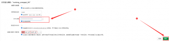
Then the following interface will pop up, click the save button in the bottom right corner.
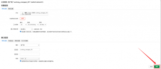
Finally, you will return to the main interface of wireless configuration, click save and apply, and wait for the configuration to be applied.
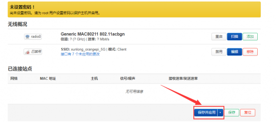
After successfully connecting to the WiFi hotspot, the interface displays as shown in the following figure.
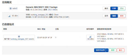


Method for creating a WIFI hotspot using a USB wireless network card
Insert the USB wireless network card into the USB port of the development board, and then connect the power supply to power on the development board.
The system startup is complete, click on Network ->Wireless to enter the wireless WiFi configuration interface.
The default wireless configuration of OpenWRT system is Master mode. For the convenience of the next operation, we will remove the default wireless connection.
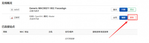
Then click on the bottom right corner of the page to save and make the configuration effective.
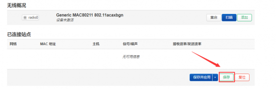
Then click the add button on the right.
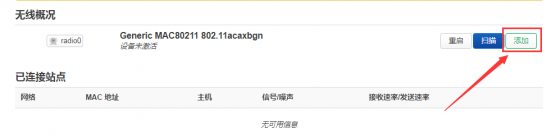
In the pop-up tab device configuration, we set the parameters as shown in the following figure.
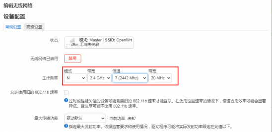
Then in Interface Configuration ->General Settings, set the mode to Access Point AP, ESSID (Wireless Network Name) to OpenWrt, and network to LAN.

Then in Interface Configuration ->Wireless Security, select WPA2-PSK as the encryption algorithm; Set the key (wireless password) to password.
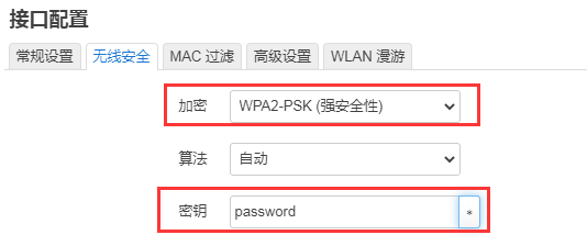
After completing the above settings, click on the bottom right corner of the page to save, and then the tab will exit.
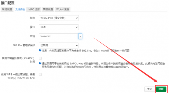
Then click on the bottom right corner of the page to save and apply, and wait for the configuration to be applied.
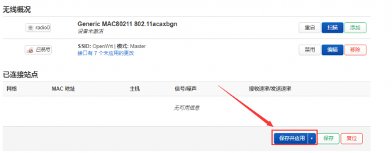
The display interface for successfully creating a hotspot is shown in the following figure:
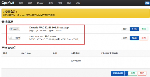
Then use your phone or computer to search for the corresponding WiFi SSID for connection. After successful connection, as shown in the following figure:
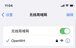


Installing software packages through the command line
Installing through OPkg on the terminal
- Update the list of available software packages
root@OpenWrt:/# opkg update
- Get software list
root@OpenWrt:/# opkg list
- Install the specified software package
root@OpenWrt:/# opkg install <Package Name>
- View installed software
root@OpenWrt:/# opkg list-installed
- Uninstall software
root@OpenWrt:/# opkg remove <Package Name>
OpenWRT management interface installation software package
If you need to add software packages, you can install them through the OpenWRT management interface.
View the list of available software packages in the system
First, enter the software package management page
Find the "System" option in the navigation bar and click to enter
In the vertical bar options below the system, select "Software Package" and click to enter

Then the main page of the software package will appear, as shown in the following figure, to obtain the list of available software
In the "Operation" option of the software package, click "Update List" to obtain the list of available software packages
On the tab page, click "Available" to view the currently available software packages
View the current number of available software packages
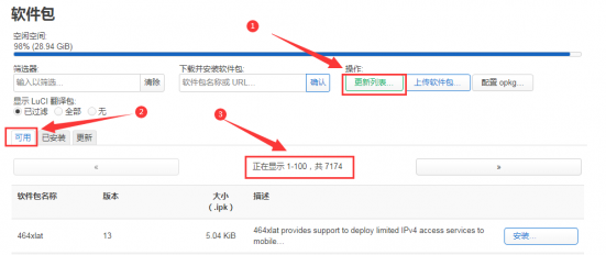

Example of Installing Software Packages
Taking the installation of the software package “luci-app-acl” as an example
In the package management interface of OpenWRT, click on the filter dialog box and enter”luci-app-acl”
In the list of software packages, you can see the version, package size, and description information of the “luci-app-acl”package, and then click the "Install" button
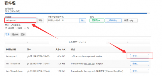
Then the following pop-up window will appear, click "Install" to proceed
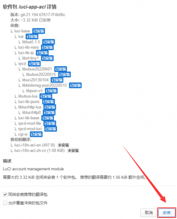
Then wait for the installation to complete


The display after installation is as follows
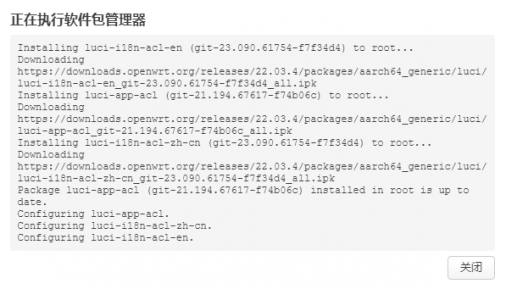

Check if the software package has been successfully installed
In the package management interface of OpenWRT, click on the filter dialog box and enter “luci-app-acl”
Select and click 'Available' on the tab page
The”luci-app-acl”package will be displayed in the package list and updated to 'installed' status
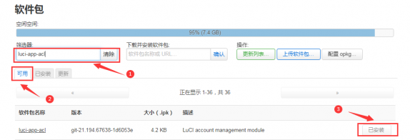

Example of Removing Software Packages
Taking the removal of the software package”luci-app-acl” as an example
In the package management interface of OpenWRT, click on the filter dialog box and enter “luci-app-acl”
Select 'Installed' on the tab page to display a list of installed software packages
Click 'Remove' on the right to remove the corresponding software package
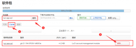
Then a pop-up window will appear below, click 'Remove' to proceed

After successful removal, the display interface is as follows
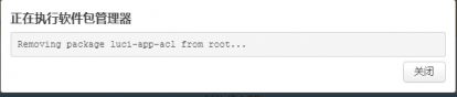
Check if the software package has been successfully removed
In the package management interface of OpenWRT, click on the filter dialog box and enter “luci-app-acl”
Select and click 'Installed' on the tab page
The”luci-app-acl”package will not be displayed in the package list, and the”luci-app-acl”package has been successfully removed
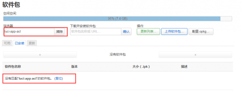


Using Samba Network Sharing
There are two main software options for implementing OpenWRT LAN file sharing: Samba and NFS. Samba system has good compatibility, while NFS performs better. For users who need to use Windows devices, it is recommended to choose Samba.
Enter the Samba network share management page
Find the "Services" option in the navigation bar and click to enter
In the vertical bar options below the service, select "Network Sharing" and click to enter

Select the interface that Samba service needs to listen on
Select "General Settings" in the navigation bar of network sharing and click to enter
Set the interface to "Lan"
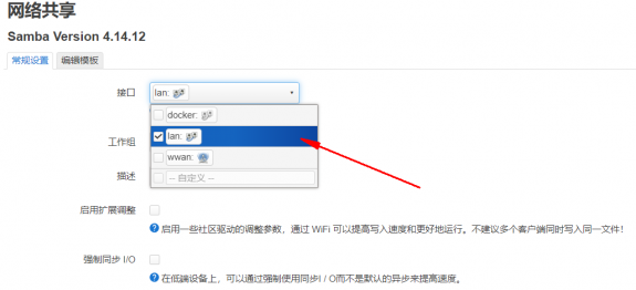


Set the shared directory for network sharing
Click "Add" in the "Shared Directory" section of the "General Settings" for network sharing to share the directory address
Enter the name of the shared folder as”mmt”under the name
Under the path of the shared directory, select the location of the shared directory "/"
Check 'browseable' and 'allow anonymous users to run'
Click 'Save and Apply' to save the configuration
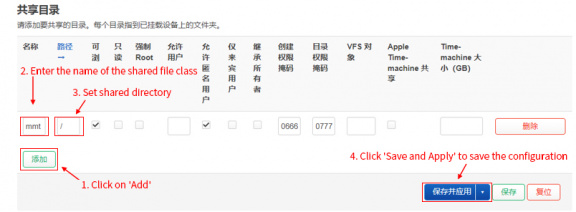
Windows 10 starts network discovery and sharing
Note: To access Samba on the Windows 10 system, it is necessary to first confirm whether Windows 10 has started network discovery and sharing. If it has not been started, the following settings should be made first.

Enable access to Samba v1/v2
Enter the Control Panel of Windows 10
Click on "Programs" in the left navigation bar of the control panel
Select 'Enable or Disable Windows Features' in Programs and Features
Check 'SMB 1.0/CIFS file sharing support' in the pop-up box to enable or disable Windows features
Click 'OK' to configure the application

Open Windows 10 Network Discovery
Enter the Control Panel of Windows 10
Select "Network and Internet" in the control panel
Then open the "Network and Sharing Center"
Click on 'Advanced Sharing Settings'
Open 'Enable Network Discovery' and 'Enable File and Printer Sharing'
Click 'Save Changes' to save the network discovery configuration for Windows 10

- After setting up, enter \ \ OpenWrt in the address bar of the resource manager to access the shared directory. The username is root and the password is the password set by the development board host

Zerotier User Manual
The OpenWRT system has pre installed the zerotier client. After creating a virtual LAN on the zerotier official website, the client can directly join it through the Network ID. The specific operation is shown below.
Log in to the zerotier official website https://my.zerotier.com/network After registering and logging in, click Network ->Create A Network to create a virtual LAN

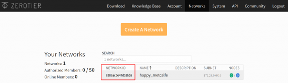
Click to enter the network console page, where you can set the privacy option to public, so that network nodes that join do not need to be verified
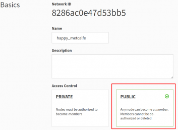
Below, the address will be automatically assigned. Here, you can choose your own network segment, and the selected one is 172.27. **
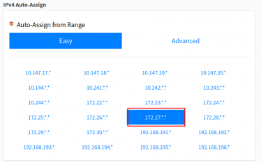
Enter the following command on the OpenWRT terminal to join the virtual LAN created above, where 8286ac0e47d53bb5 is the Network ID of the virtual LAN created above


root@OpenWrt:/# zerotier-one -d #Start the zerotier client
root@OpenWrt:/# zerotier-cli join 8286ac0e47d53bb5 #Join the network
- By entering ifconfig on the terminal, it can be seen that there is already a newly added ztks54inm2 device with an IP address of 172.27.214.213
root@OpenWrt:/# ifconfig
ztks54inm2 Link encap:Ethernet HWaddr F6:4E:DE:BF:D8:52
inet addr:172.27.214.213 Bcast:172.27.255.255 Mask:255.255.0.0
inet6 addr: fe80::e82f:d0ff:fe5a:867e/64 Scope:Link
UP BROADCAST RUNNING MULTICAST MTU:2800 Metric:1
RX packets:18 errors:0 dropped:0 overruns:0 frame:0
TX packets:48 errors:0 dropped:0 overruns:0 carrier:0
collisions:0 txqueuelen:1000
RX bytes:1720 (1.6 KiB) TX byte81 (8.2 KiB)
- Install the zerotier client on another device (using Ubuntu 18.04 as an example), execute the following command to install, and restart the computer after installation is complete
test@ubuntu:~$ curl -s https://install.zerotier.com | sudo bash
- After restarting, join the virtual LAN based on the Network ID, and you can also see that the IP address assigned by zerotier has been obtained. At this time, the Ubuntu PC and the development board are in the same LAN, and they can communicate freely
test@ubuntu:~$ sudo zerotier-cli join 8286ac0e47d53bb5
test@ubuntu:~$ ifconfig
ztks54inm2: flags=4163<UP,BROADCAST,RUNNING,MULTICAST> mtu 2800
inet 172.27.47.214 netmask 255.255.0.0 broadcast 172.27.255.255
inet6 fe80::5ce1:85ff:fe2b:6918 prefixlen 64 scopeid 0x20<link>
ether f6:fd:87:68:12:cf txqueuelen 1000 (Ethernet)
RX packets 0 bytes 0 (0.0 B)
RX errors 0 dropped 0 overruns 0 frame 0
TX packets 46 bytes 10006 (10.0 KB)
TX errors 0 dropped 0 overruns 0 carrier 0 collisions 0
- Test whether two terminals can communicate
root@OpenWrt:/# ping 172.27.47.214 -I ztks54inm2
PING 172.27.47.214 (172.27.47.214): 56 data bytes
64 bytes from 172.27.47.214: seq=0 ttl=64 time=1.209 ms
64 bytes from 172.27.47.214: seq=1 ttl=64 time=1.136 ms
64 bytes from 172.27.47.214: seq=2 ttl=64 time=1.203 ms
64 bytes from 172.27.47.214: seq=3 ttl=64 time=1.235 ms
^C
--- 172.27.47.214 ping statistics ---
4 packets transmitted, 4 packets received, 0% packet loss
round-trip min/avg/max = 1.136/1.195/1.235 ms
- Zerotier other commonly used commands
root@OpenWrt:/# zerotier-one -d #Start the zerotier client
root@OpenWrt:/# zerotier-cli status #Obtain address and service status
root@OpenWrt:/# zerotier-cli join # Network ID #Join the network
root@OpenWrt:/# zerotier-cli leave # Network ID #Leave the internet
root@OpenWrt:/# zerotier-cli listnetworks #List networks
OPENWRT_DEVICE_REVISION="v0"
OPENWRT_RELEASE="OpenWrt 22.03.4 r20123-38ccc47687"
Compilation method of OpenWRT source code
Download OpenWRT source code
- First, execute the following command to download the openwrt-22.03 branch code
test@test:~$ sudo apt update
test@test:~$ sudo apt install -y git
test@test:~$ git clone https://github.com/orangepi-xunlong/openwrt.git -b openwrt-22.03
- After downloading the OpenWRT code, the following files and folders will be included
test@test:~/openwrt$ ls
BSDmakefile Config.in include Makefile README.md scripts toolchain
Config feeds.conf.default LICENSE package rules.mk target tools
Compile OpenWRT source code
- Firstly, install the following dependency packages (currently only tested for compilation on Ubuntu 22.04. If compiling on other versions of Ubuntu systems, please install the corresponding dependency packages according to the error message)
test@test:~/openwrt$ sudo apt update
test@test:~/openwrt$ sudo apt install -y ack antlr3 asciidoc autoconf \
automake autopoint binutils bison build-essential \
bzip2 ccache cmake cpio curl device-tree-compiler fastjar \
flex gawk gettext gcc-multilib g++-multilib git gperf haveged \
help2man intltool libc6-dev-i386 libelf-dev libglib2.0-dev \
libgmp3-dev libltdl-dev libmpc-dev libmpfr-dev \
libncurses5-dev \libncursesw5-dev libreadline-dev libssl-dev \
libtool lrzsz mkisofs msmtp nano ninja-build p7zip p7zip-full \
patch pkgconf python2.7 python3 python3-pyelftools \
libpython3-dev qemu-utils rsync scons squashfs-tools \
subversion swig texinfo uglifyjs upx-ucl unzip \
vim wget xmlto xxd zlib1g-dev
- Then execute./scripts/feeds update -a and./scripts/feeds install -a download dependency package
test@test:~/openwrt$ ./scripts/feeds update -a
test@test:~/openwrt$ ./scripts/feeds install -a
Then choose to use the configuration file for OrangePi 5 Ultra
test@test:~/openwrt$ cp configs/orangepi-5-ultra-rk3588_defconfig .config
Then execute the following command to make the configuration effective
test@test:~/openwrt$ make defconfig
- Execute the following command to start compiling the openwrt source code
test@test:~/openwrt$ make V=s
- After compilation, the path where the image is generated is:
bin/targets/rockchip/armv8/openwrt-rockchip-armv8-xunlong_orangepi-5-ultra-ext4-sysupgrade.img.gz
Appendix
User Manual Update History
| Version | Date | Update Explanation |
| v1.0 | 2024-10-10 | Initial version |
Image update history
| Date | Update Explanation |
| 2024-10-10 | Oran gepi5ultra_1.0.0_ubuntu_focal_server_linux5.10.160.7z
Oran gepi5ultra_1.0.0_ubuntu_jammy_server_linux5.10.160.7z Orangep i5ultra_1.0.0_debian_bullseye_server_linux5.10.160.7z Orangep i5ultra_1.0.0_debian_bookworm_server_linux5.10.160.7z Orangepi5u ltra_1.0.0_ubuntu_focal_desktop_xfce_linux5.10.160.7z Orangepi5u ltra_1.0.0_ubuntu_jammy_desktop_xfce_linux5.10.160.7z Orangepi5ultr a_1.0.0_debian_bullseye_desktop_xfce_linux5.10.160.7z Orangepi5ultr a_1.0.0_debian_bookworm_desktop_xfce_linux5.10.160.7z Orangepi5ul tra_1.0.0_ubuntu_jammy_desktop_gnome_linux5.10.160.7z Or angepi5ultra_1.0.0_ubuntu_jammy_server_linux6.1.43.7z Orang epi5ultra_1.0.0_debian_bookworm_server_linux6.1.43.7z Orangepi 5ultra_1.0.0_ubuntu_jammy_desktop_xfce_linux6.1.43.7z Orangepi5ult ra_1.0.0_debian_bookworm_desktop_xfce_linux6.1.43.7sz OrangePi5Ultra_RK3588_Android13_v1.0.0.tar.gz O rangePi5Ultra_RK3588_Android13_spi-nvme_v1.0.0.tar.gz Opi os-droid-aarch64-opi5ultra-24.09-linux5.10.160.tar.gz Opios-droid- aarch64-opi5ultra-24.09-linux5.10.160-spi-nvme.tar.gz Opios-ar ch-aarch64-gnome-opi5ultra-24.08-linux5.10.160.img.xz openwrt-rockchip-armv 8-xunlong_orangepi-5ultra-ext4-sysupgrade_v1.0.img.gz
|