Orange Pi 5 detail
Contents
- 1 How to use Win32Diskimager to burn Linux image
- 2 Linux system instructions
- 2.1 Supported Linux image types and kernel versions
- 2.2 Onboard LED Light Test Instructions
- 2.3 Ethernet port test
- 2.4 WIFI connection test
- 2.5 How to set a static IP address
- 2.6 How to use AP6275P PCIe network card
- 2.7 AP6275P PCIe NIC creates WIFI hotspot via create_ap
- 2.8 HDMI display test
- 2.9 HDMI to VGA display test
- 2.10 HDMI resolution setting method
- 2.11 How to use Bluetooth
- 2.12 USB interface test
- 2.13 Connect USB mouse or keyboard to test
- 2.14 Connect USB storage device test
- 2.15 USB wireless network card test
- 2.16 USB camera test
- 2.17 Testing audio methods on desktop systems
- 2.18 The method of using commands to play audio
- 2.19 Method of using commands to test recording
- 2.20 26 Pin Interface Pin Description
- 3 Instructions for the use of the android 12 system
How to use Win32Diskimager to burn Linux image
1) First prepare a TF card with a capacity of 16GB or more. The transmission speed of the TF card must be class 10 or above. It is recommended to use a TF card of SanDiskand other brands
2) Then use the card reader to insert the TF card into the computer
3) Then format the TF card
a. SD Card Formatter can be used to format the TF card. The download address is:
https://www.sdcard.org/downloads/formatter/eula_windows/SDCardFormatterv5_WinEN.zip
b. After downloading, unzip and install directly, and then open the software
c. If only a TF card is inserted into the computer, the drive letter of the TF card will be displayed in the "Select card" column. If multiple USB storage devices are inserted into the computer, you can select the corresponding drive letter of the TF card through the drop-down box

d. Then click "Format", a warning box will pop up before formatting, and formatting will start after selecting "Yes (Y)"

e. After formatting the TF card, the information shown in the figure below will pop up, click OK

4) Download the Linux operating system image file compression package that you want to burn from the Orange Pi data download page, and then use the decompression software to decompress it. Among the decompressed files, the file ending with ".img" is the image file of the operating system. The size is generally more than 2GB
5) Use Win32Diskimager to burn the Linux image to the TF card
a. The download page of Win32Diskimager is
http://sourceforge.net/projects/win32diskimager/files/Archive/
b. After downloading, install it directly. The interface of Win32Diskimager is as follows
a) First select the path of the image file
b) Then confirm that the drive letter of the TF card is consistent with that displayed in the "Device" column
c) Finally click "Write" to start burning

c. After the image writing is completed, click the "Exit" button to exit, and then you can pull out the TF card and insert it into the development board to start
Linux system instructions
Supported Linux image types and kernel versions
| Linux image type | kernel version | server version | desktop version |
| Debian 11 - Bullseye | Linux5.10 | support | support |
| Ubuntu 20.04 - Focal | Linux5.10 | support | support |
| Ubuntu 22.04 - Jammy | Linux5.10 | support | support |
Onboard LED Light Test Instructions
1) There are two LED lights on the development board, one is green and the other is red. The location is shown in the figure below:

2) As long as the development board is powered on, the red LED light will always be on, which is controlled by the hardware and cannot be turned off by the software.
3) The green LED light will keep flashing after the kernel is started, which is controlled by software.
4) The method of setting the green light on and off and flashing is as follows
| Note that the following operations should be performed under the root user. |
a. First enter the setting directory of the green light
| root@orangepi:~# cd /sys/class/leds/status_led |
b. The command to set the green light to stop flashing is as follows
| root@orangepi:/sys/class/leds/status_led# echo none > trigger |
c. The command to set the green light to be on is as follows
| root@orangepi:/sys/class/leds/status_led# echo 1 > brightness |
d. The command to set the green light to flash is as follows
| root@orangepi:/sys/class/leds/status_led# echo heartbeat > trigger |
Ethernet port test
1) First, insert one end of the network cable into the Ethernet interface of the development board, and connect the other end of the network cable to the router, and ensure that the network is unblocked
2) After the system starts, it will automatically assign an IP address to the Ethernet card through DHCP,No other configuration is required
3) The command to view the IP address in the Linux system of the development board is as follows
| orangepi@orangepi:~$ ip addr show eth0 2: eth0: <BROADCAST,MULTICAST,UP,LOWER_UP> mtu 1500 qdisc mq state UP group default qlen 1000 |
| When using ifconfig to view the IP address, if the following information is displayed, it is because sudo is not added. The correct command is:sudo ifconfig Command 'ifconfig' is available in the following places |
| There are three ways to check the IP address after the development board starts: 1. Connect the HDMI monitor, then log in to the system and use the ip addr show eth0 command to view the IP address In addition, it should be noted that the development board DHCP automatically assigns an IP address without any settings. |
4) The command to test the network connectivity is as follows, the ping command can be interrupted through the shortcut key of Ctrl+C
| orangepi@orangepi:~$ ping www.baidu.com -I eth0 PING www.a.shifen.com (14.215.177.38) from 192.168.1.12 eth0: 56(84) bytes of data. |
WIFI connection test
| Please do not connect to WIFI by modifying the /etc/network/interfaces configuration file. There will be problems connecting to the WIFI network in this way. |
1. The server image connects to WIFI through commands
| When the development board is not connected to Ethernet, not connected to HDMI display, but only connected to the serial port, it is recommended to use the commands demonstrated in this section to connect to the WIFI network. Because nmtui can only display characters in some serial port software (such as minicom), and cannot display the graphical interface normally. Of course, if the development board is connected to an Ethernet or HDMI display, you can also use the commands demonstrated in this section to connect to the WIFI network. |
1) First log in to the linux system, there are the following three ways
a. If the development board is connected with a network cable, you can remotely log in to the Linux system through ssh
b. If the development board is connected to the debugging serial port, you can use the serial port terminal to log in to the Linux system
c. If the development board is connected to the HDMI display, you can log in to the linux system through the terminal displayed on the HDMI
2) First use the nmcli dev wifi command to scan the surrounding WIFI hotspots
| orangepi@orangepi:~$ nmcli dev wifi |
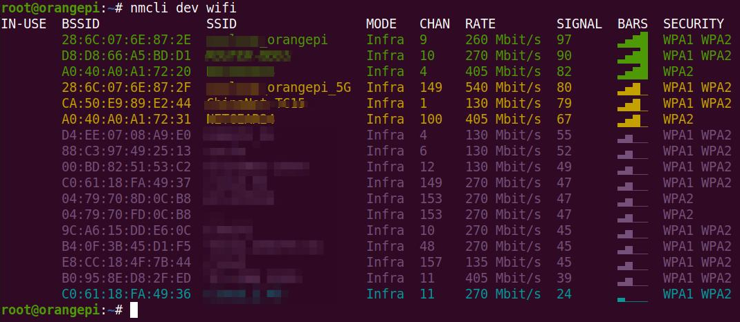
3) Then use the nmcli command to connect to the scanned WIFI hotspot, where:
a. wifi_name needs to be replaced with the name of the WIFI hotspot you want to connect to
b. wifi_passwd needs to be replaced with the password of the WIFI hotspot you want to connect to
| orangepi@orangepi:~$ nmcli dev wifi connect wifi_name password wifi_passwd
Device 'wlan0' successfully activated with 'cf937f88-ca1e-4411-bb50-61f402eef293'. |
4) You can view the IP address of wifi through the ip addr show wlan0 command
| orangepi@orangepi:~$ ip addr show wlan0 11: wlan0: <BROADCAST,MULTICAST,UP,LOWER_UP> mtu 1500 qdisc pfifo_fast state UP group default qlen 1000 |
5) Use the ping command to test the connectivity of the wifi network, and the ping command can be interrupted through the shortcut key Ctrl+C
| orangepi@orangepi:~$ ping www.orangepi.org -I wlan0 PING www.orangepi.org (182.92.236.130) from 192.168.1.49 wlan0: 56(84) bytes of data. |
2. The server image connects to WIFI in a graphical way
1) First log in to the linux system, there are the following three ways
a. If the development board is connected with a network cable, you can remotely log in to the Linux system through ssh
b. If the development board is connected to the debugging serial port, you can use the serial port terminal to log in to the linux system (please use MobaXterm for the serial port software, and minicom cannot display the graphical interface)
c. If the development board is connected to the HDMI display, you can log in to the linux system through the terminal displayed on the HDMI
2) Then enter the nmtui command in the command line to open the wifi connection interface
| orangepi@orangepi:~$ nmtui |
3) Enter the nmtui command to open the interface as shown below
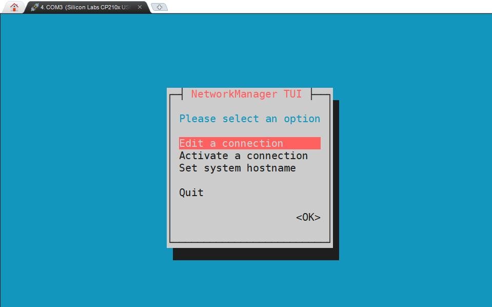
4) Select Activate a connect and press Enter
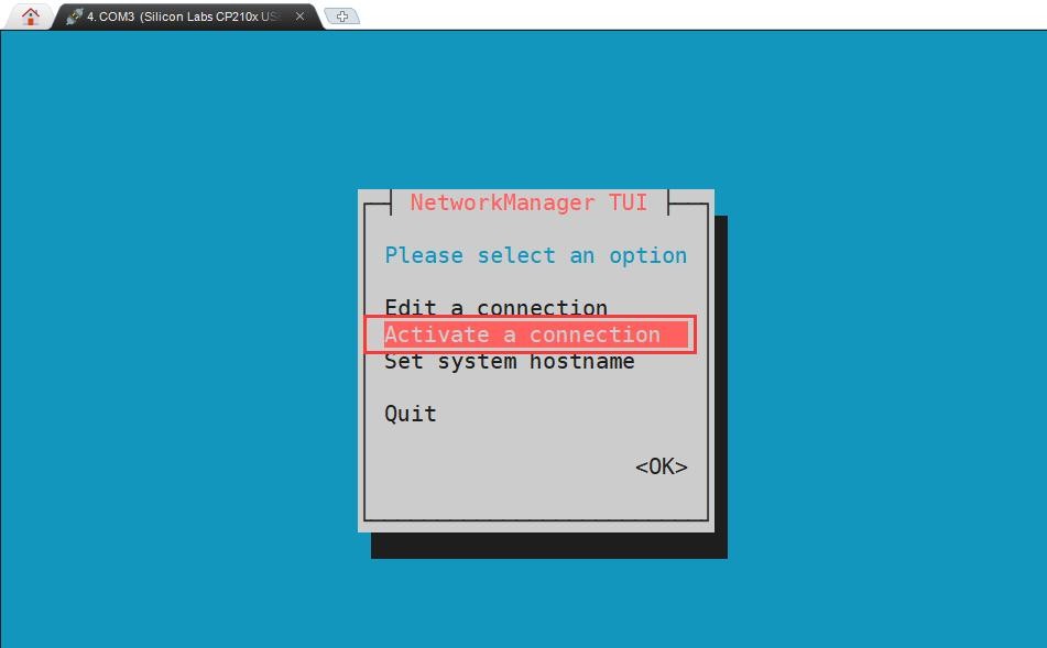
5) Then you can see all the searched WIFI hotspots
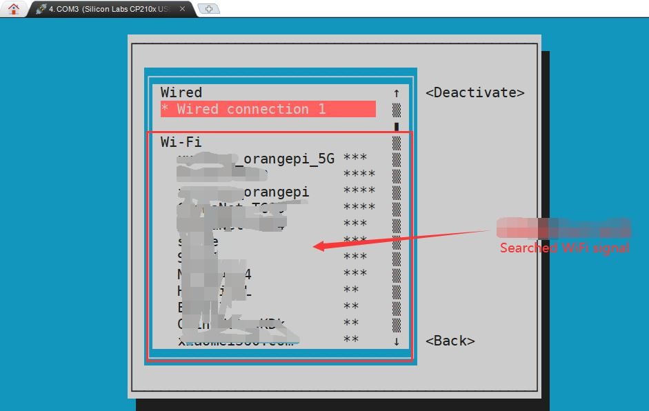
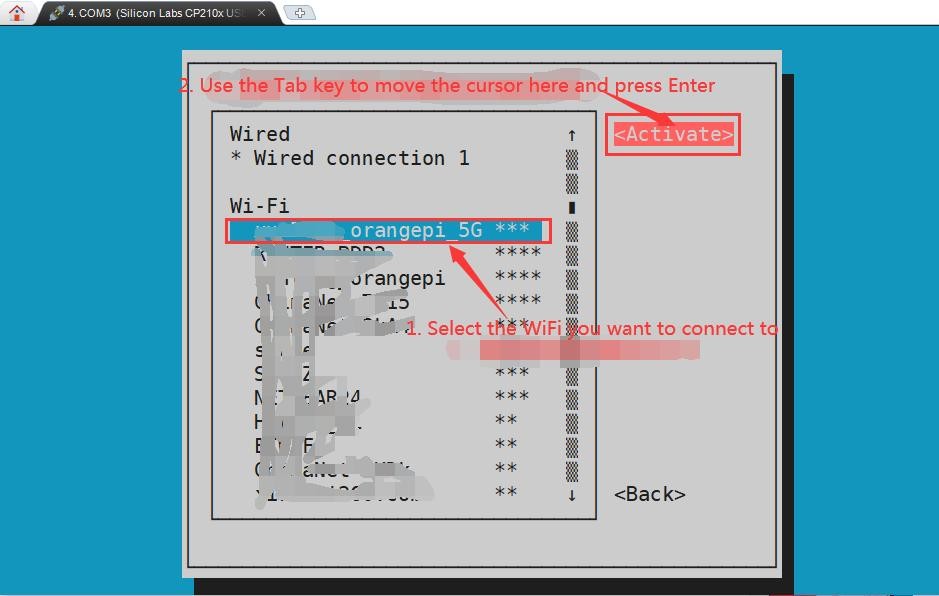
6) Select the WIFI hotspot you want to connect to, then use the Tab key to position the cursor on Activate and press Enter
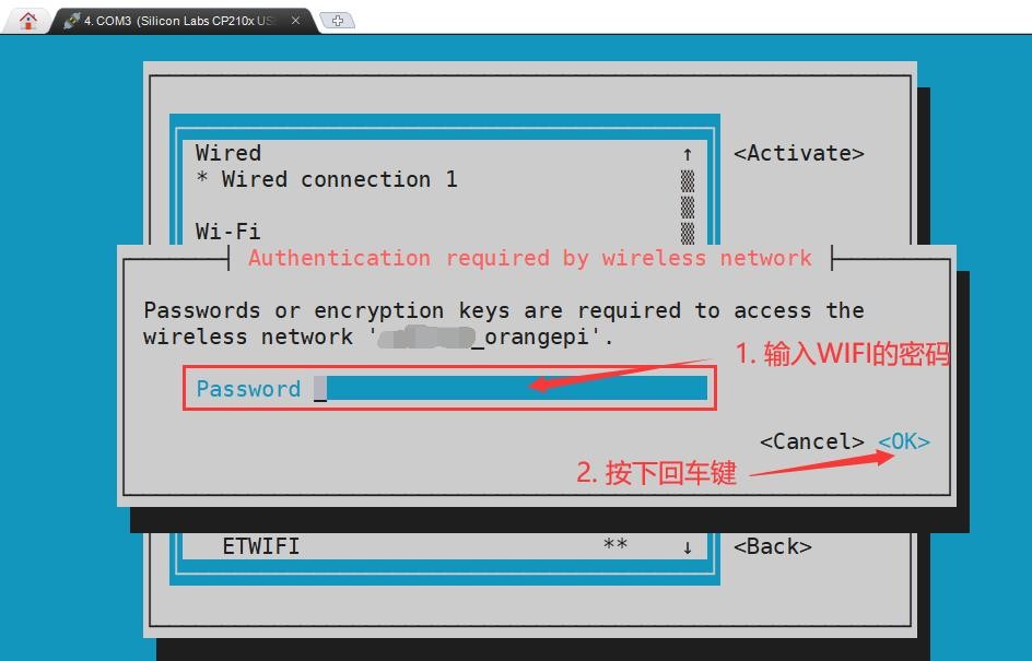
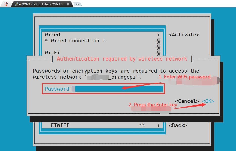
7) Then a dialog box for entering a password will pop up, enter the corresponding password in Password and press Enter to start connecting to WIFI
8) After the WIFI connection is successful, a "*" will be displayed in front of the connected WIFI name
9) You can view the IP address of wifi through the ip addr show wlan0 command
| orangepi@orangepi:~$ ip addr show wlan0 11: wlan0: <BROADCAST,MULTICAST,UP,LOWER_UP> mtu 1500 qdisc pfifo_fast state UP group default qlen 1000 |
10) Use the ping command to test the connectivity of the wifi network, and the ping command can be interrupted through the shortcut key Ctrl+C
| orangepi@orangepi:~$ ping www.orangepi.org -I wlan0 PING www.orangepi.org (182.92.236.130) from 192.168.1.49 wlan0: 56(84) bytes of data. |
3. Test method of desktop image
1) Click the network configuration icon in the upper right corner of the desktop (please do not connect the network cable when testing WIFI)

2) Click More networks in the pop-up drop-down box to see all scanned WIFI hotspots, and then select the WIFI hotspot you want to connect to

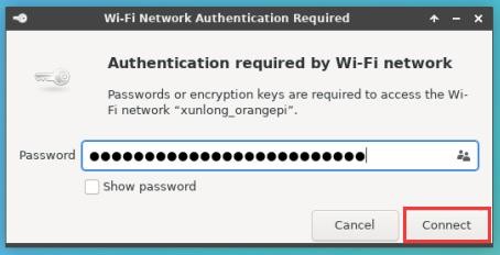
3) Then enter the password of the WIFI hotspot, and then click Connect to start connecting to WIFI
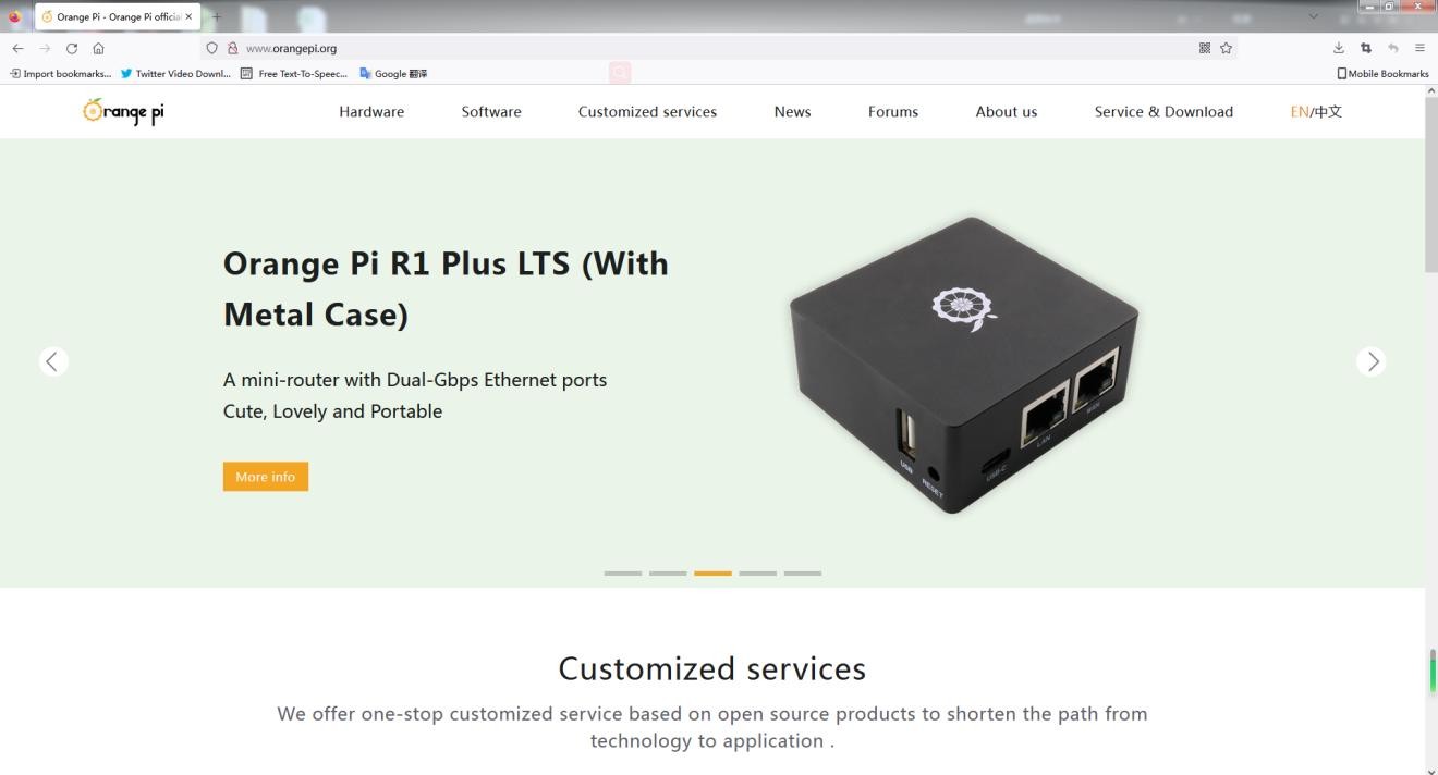
4) After connecting to WIFI, you can open the browser to check whether you can access the Internet. The entrance of the browser is shown in the figure below

5) If you can open other web pages after opening the browser, it means that the WIFI connection is normal
How to set a static IP address
1.Use the nmtui command to set a static IP address
1) First run the nmtui command
| orangepi@orangepi:~$ nmtui |
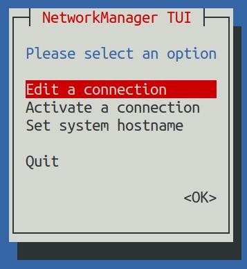
2) Then select Edit a connection and press Enter
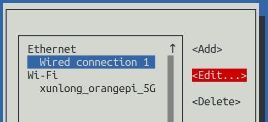
3) Then select the network interface that needs to set a static IP address, for example, to set the static IP address of the Ethernet interface, select Wired connection 1
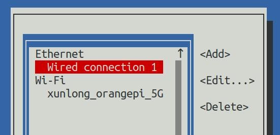
4) Then select Edit via the Tab key and press the Enter key
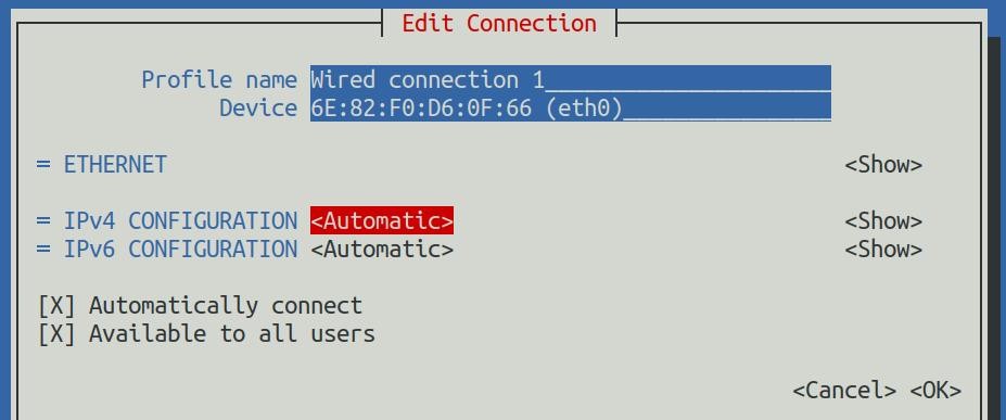
5) Then use the Tab key to move the cursor to the <Automatic> position shown in the figure below to configure IPv4
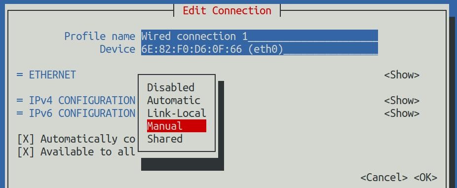
6) Then press Enter, select Manual through the up and down arrow keys, and press Enter to confirm
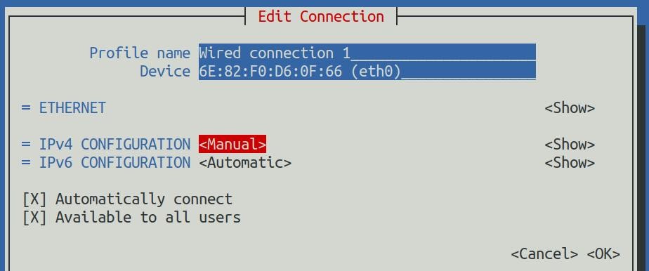
7) The display after selection is shown in the figure below
8) Then move the cursor to <Show> via the Tab key
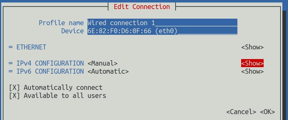
9) Then press Enter, and the following setting interface will pop up after entering
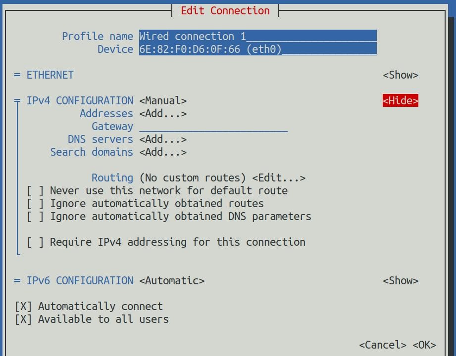
10) Then you can set the IP address (Addresses), gateway (Gateway) and DNS server address in the position shown in the figure below (there are many other setting options in it, please explore by yourself),Please set it according to your specific needs, the value set in the figure below is just an example
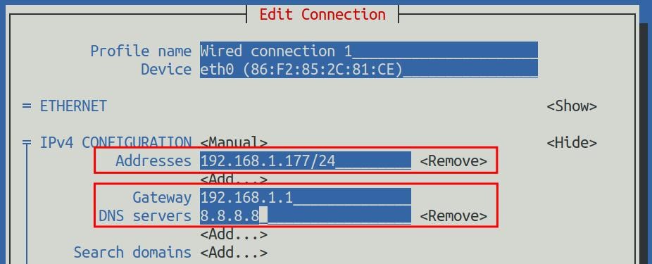
11) After setting, move the cursor to <OK> in the lower right corner, and press Enter to confirm

12) Then click <Back> to return to the previous selection interface
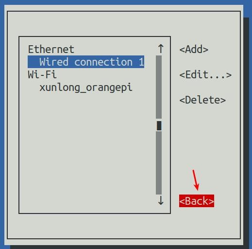
13) Then select Activate a connection, then move the cursor to <OK>, and finally click Enter
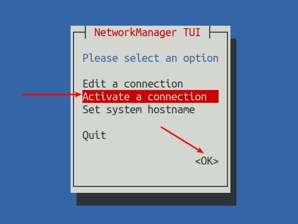
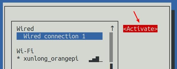
14) Then select the network interface that needs to be set, such as Wired connection 1, then move the cursor to <Deactivate>, and press Enter to disable Wired connection 1

15) Then please do not move the cursor, and then press the Enter key to re-enable Wired connection 1, so that the static IP address set earlier will take effect
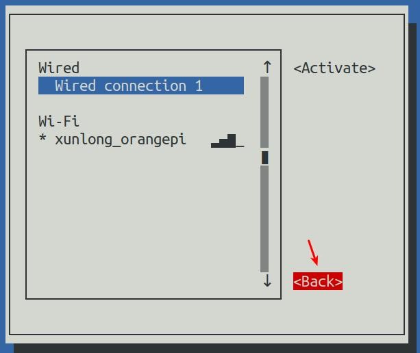
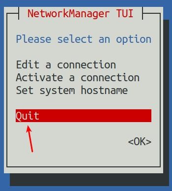
16) Then you can exit nmtui through the <Back> and Quit buttons
17) Then through ip addr show eth0, you can see that the IP address of the network port has changed to the static IP address set earlier
| orangepi@orangepi:~$ ip addr show eth0 3: eth0: <BROADCAST,MULTICAST,UP,LOWER_UP> mtu 1500 qdisc pfifo_fast state UP group default qlen 1000 |
18) Then you can test the connectivity of the network to check whether the IP address is configured OK, and the ping command can be interrupted through the shortcut key Ctrl+C
| orangepi@orangepi:~$ ping 192.168.1.47 -I eth0 PING 192.168.1.47 (192.168.1.47) from 192.168.1.188 eth0: 56(84) bytes of data. |
2.Use the nmcli command to set a static IP address
1) If you want to set the static IP address of the network port, please insert the network cable into the development board first. If you need to set the static IP address of WIFI, please connect the WIFI first, and then start to set the static IP address
2) Then you can view the name of the network device through the nmcli con show command, as shown below
a. orangepi is the name of the WIFI network interface (the name is not necessarily the same)
b. Wired connection 1 is the name of the Ethernet interface
| orangepi@orangepi:~$ nmcli con show |
| NAME | UUID | TYPE | DEVICE |
| orangepi | cfc4f922-ae48-46f1-84e1-2f19e9ec5e2a | wifi | wlan0 |
| Wired connection 1 | 9db058b7-7701-37b8-9411-efc2ae8bfa30 | ethernet | eth0 |
3) Then enter the following command, where
a. "Wired connection 1" means to set the static IP address of the Ethernet port. If you need to set the static IP address of the WIFI, please modify it to the corresponding name of the WIFI network interface (you can get it through the nmcli con show command)
b. ipv4.addresses is followed by the static IP address to be set, which can be modified to the value you want to set
c. ipv4.gateway represents the address of the gateway
| orangepi@orangepi:~$ nmcli con mod "Wired connection 1" \ ipv4.addresses "192.168.1.110" \ |
4) Then restart the linux system
| orangepi@orangepi:~$ sudo reboot |
5) Then re-enter the linux system and use the ip addr show eth0 command to see that the IP address has been set to the desired value
| orangepi@orangepi:~$ ip addr show eth0 3: eth0: <BROADCAST,MULTICAST,UP,LOWER_UP> mtu 1500 qdisc pfifo_fast state UP group default qlen 1000 |
How to use AP6275P PCIe network card
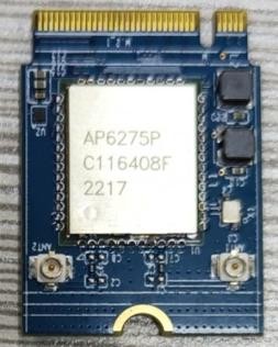
1) First, you need to purchase an AP6275P PCIe network card as shown in the figure below
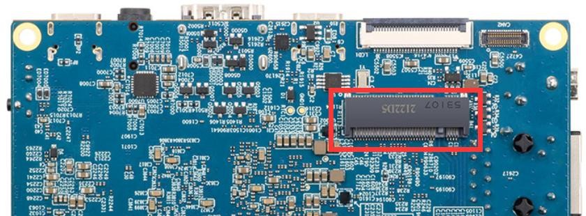
2) Then insert the AP6275P PCIe network card into the M.2 interface of the development board and fix it
3) Then open the configuration of the AP6275P PCIe network card in the linux system, the steps are as follows:
a. First run orangepi-config, normal users remember to add sudo permission
| orangepi@orangepi:~$ sudo orangepi-config |
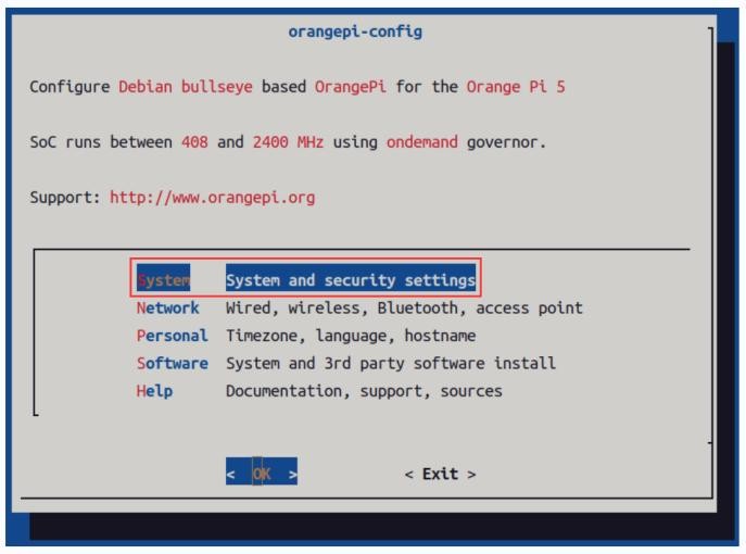
b. Then select System
c. Then select Hardware
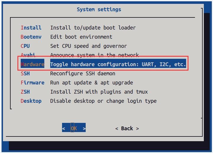
d. Then use the arrow keys on the keyboard to navigate to wifi-ap6275p, and then use the space to select
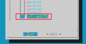
e. Then select <Save> to save

f. Then select <Back>

g. Then select <Reboot> to restart the system to make the configuration take effect

| The above settings will eventually add the configuration of overlays=wifi-ap6275p to /boot/orangepiEnv.txt. After setting, you can check it first. If this configuration does not exist, then there is a problem with the settings. If you find it troublesome to use orangepi-config, you can also open /boot/orangepiEnv.txt, and then add the configuration of overlays=wifi-ap6275p. |
4) If everything is normal after restarting the system, use the following command to see the device nodes of WIFI and Bluetooth
a. The command to view the WIFI device node is as follows:
| orangepi@orangepi:~$ ip addr show wlan0 3: wlan0: <NO-CARRIER,BROADCAST,MULTICAST,UP,LOWER_UP> mtu 1500 |
b. The command to view the Bluetooth device node is as follows:
| orangepi@orangepi:~$ hciconfig -a hci0: Type: Primary Bus: UART |
5) For the wifi connection and test method, please refer to the section of WIFI connection test, which will not be repeated here
6) For the test method of Bluetooth, please refer to the section on Bluetooth usage, so I won’t go into details here
AP6275P PCIe NIC creates WIFI hotspot via create_ap
| create_ap is a script that helps quickly create WIFI hotspots on Linux, and supports bridge and NAT modes. It can automatically combine hostapd, dnsmasq and iptables to complete the setting of WIFI hotspots, avoiding complex configuration for users. The github address is as follows: |
| If you using the latest image, the create_ap script has been pre-installed, and you can create a WIFI hotspot through the create_ap command. The basic command format of create_ap is as follows: create_ap [options] <wifi-interface> [<interface-with-internet>] |
1.create_ap method to create WIFI hotspot in NAT mode
1) Enter the following command to create a WIFI hotspot named orangepi and password orangepi in NAT mode
| orangepi@orangepi5:~$ sudo create_ap -m nat wlan0 eth0 orangepi orangepi |
2) If the following information is output, it means that the WIFI hotspot is created successfully
| orangepi@orangepi5:~$ sudo create_ap -m nat wlan0 eth0 orangepi orangepi Config dir: /tmp/create_ap.wlan0.conf.fPItFUJ2 PID: 3831 |
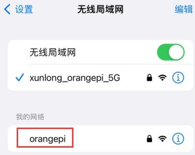
3) Take out the mobile phone at this time, in the searched WIFI list, you can find the WIFI hotspot named orangepi created by the development board, and then click orangepi to connect to the hotspot, the password is the orangepi set above
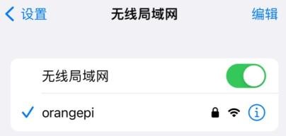
4) After the connection is successful, the display is as shown in the figure below
5) In NAT mode, the wireless device connected to the hotspot of the development board requests an IP address from the DHCP service of the development board, so there will be two different network segments, for example, the IP of the development board is 192.168.1.X
| orangepi@orangepi5:~$ ifconfig eth0 eth0: flags=4163<UP,BROADCAST,RUNNING,MULTICAST> mtu 1500 |
By default, the DHCP service of the development board will assign an IP address of 192.168.12.0/24 to the device connected to the hotspot. At this time, click on the connected WIFI hotspot orangepi, and then you can see that the IP address of the mobile phone is 192.168.12.X
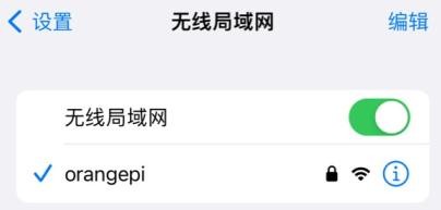
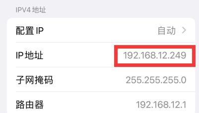
6) If you want to specify a different network segment for the connected device, you can specify it through the -g parameter, such as specifying the network segment of the access point AP through the -g parameter as 192.168.2.1
| orangepi@orangepi5:~$ sudo create_ap -m nat wlan0 eth0 orangepi orangepi -g 192.168.2.1 |
At this time, after connecting to the hotspot through the mobile phone, click the connected WIFI hotspot orangepi, and then you can see that the IP address of the mobile phone is 192.168.2.X
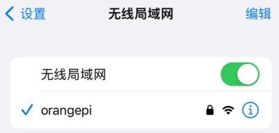
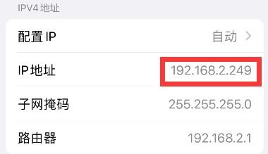
7) If the --freq-band parameter is not specified, the hotspot created by default is in the 2.4G frequency band. If you want to create a hotspot in the 5G frequency band, you can specify it through the --freq-band 5 parameter. The specific command is as follows
| orangepi@orangepi:~$ sudo create_ap -m nat wlan0 eth0 orangepi orangepi --freq-band 5 |
8) If you need to hide the SSID, you can specify the --hidden parameter, the specific command is as follows
| orangepi@orangepi:~$ sudo create_ap -m nat wlan0 eth0 orangepi orangepi --hidden |
At this time, the mobile phone cannot search for the WIFI hotspot. You need to manually specify the name of the WIFI hotspot and enter the password to connect to the WIFI hotspot

2.create_ap method to create WIFI hotspot in bridge mode
1) Enter the following command to create a WIFI hotspot named orangepi and password orangepi in bridge mode
| orangepi@orangepi:~$ sudo create_ap -m bridge wlan0 eth0 orangepi orangepi |
2) If the following information is output, it means that the WIFI hotspot is created successfully
| orangepi@orangepi:~$ sudo create_ap -m bridge wlan0 eth0 orangepi orangepi [sudo] password for orangepi: |
3) Take out the mobile phone at this time, and you can find the WIFI hotspot named orangepi created by the development board in the searched WIFI list, and then you can click orangepi to connect to the hotspot, and the password is the orangepi set above
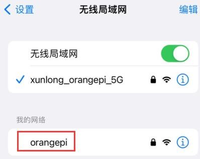
4) After the connection is successful, the display is as shown in the figure below
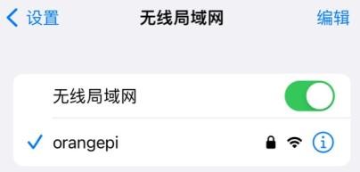
5) In bridge mode, the wireless device connected to the hotspot of the development board also requests an IP address from the DHCP service of the main router (the router connected to the development board), for example, the IP of the development board is 192.168.1.X
| orangepi@orangepi:~$ ifconfig eth0 eth0: flags=4163<UP,BROADCAST,RUNNING,MULTICAST> mtu 1500 |
The IP of the device connected to the WIFI hotspot is also assigned by the main router, so the mobile phone connected to the WIFI hotspot and the development board are in the same network segment. At this time, click on the connected WIFI hotspot orangepi, and then you can see the IP address of the mobile phone Also 192.168.1.X
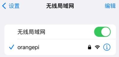
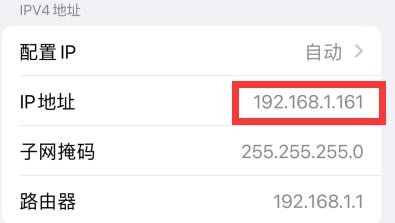
6) If the --freq-band parameter is not specified, the hotspot created by default is in the 2.4G frequency band. If you want to create a hotspot in the 5G frequency band, you can specify the --freq-band 5 parameter. The specific command is as follows
| orangepi@orangepi:~$ sudo create_ap -m bridge wlan0 eth0 orangepi orangepi --freq-band 5 |
7) If you need to hide the SSID, you can specify the --hidden parameter, the specific command is as follows
| orangepi@orangepi:~$ sudo create_ap -m bridge wlan0 eth0 orangepi orangepi --hidden |
At this time, the mobile phone cannot search for the WIFI hotspot. You need to manually specify the name of the WIFI hotspot and enter the password to connect to the WIFI hotspot.

HDMI display test
1) Use HDMI to HDMI cable to connect Orange Pi development board and HDMI display

2) After starting the linux system, if the HDMI monitor has image output, it means that the HDMI interface is working normally
| Note that although many notebook computers have an HDMI interface, the HDMI interface of the notebook generally only has the output function, and does not have the function of HDMI in, that is to say, the HDMI output of other devices cannot be displayed on the notebook screen. When you want to connect the HDMI of the development board to the HDMI port of the laptop, please make sure that your laptop supports the HDMI in function. |
| When the HDMI is not displayed, please check whether the HDMI cable is plugged in tightly. After confirming that there is no problem with the connection, you can change a different screen and try to see if it is displayed. |
HDMI to VGA display test
1) First, you need to prepare the following accessories
a. HDMI to VGA Converter
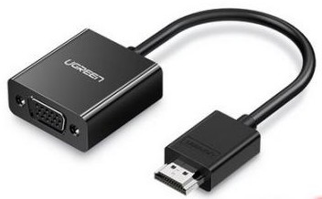
b. A VGA cable

c. A monitor or TV that supports VGA interface
2) HDMI to VGA display test as shown below
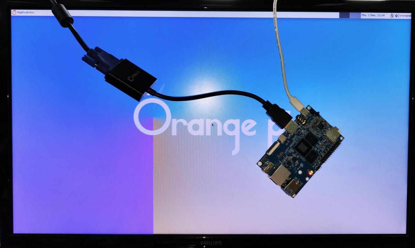
| When using HDMI to VGA display, the development board and the Linux system of the development board do not need to make any settings, only the HDMI interface of the development board can display normally. So if there is a problem with the test, please check whether there is a problem with the HDMI to VGA converter, VGA cable and monitor. |
HDMI resolution setting method
1) First open Display in Settings

2) Then you can see the current resolution of the system
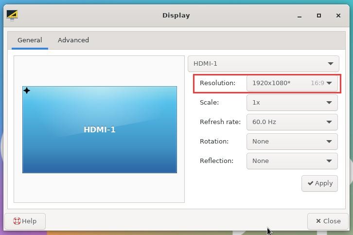
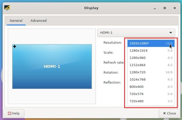
3) Click the drop-down box of Resolution to see all resolutions currently supported by the display
4) Then select the resolution you want to set, and click Apply
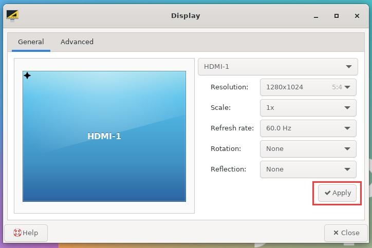
5) After the new resolution is set, select Keep the configuration

How to use Bluetooth
1.Test method of desktop image
1) Click the Bluetooth icon in the upper right corner of the desktop

2) Then select the adapter

3) If there is a prompt on the following interface, please select Yes

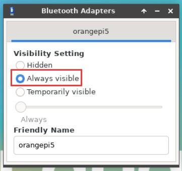
4) Then set the Visibility Setting to Always visible in the Bluetooth adapter setting interface, and then close it
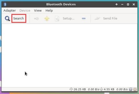
5) Then open the configuration interface of the Bluetooth device

6) Click Search to start scanning the surrounding Bluetooth devices
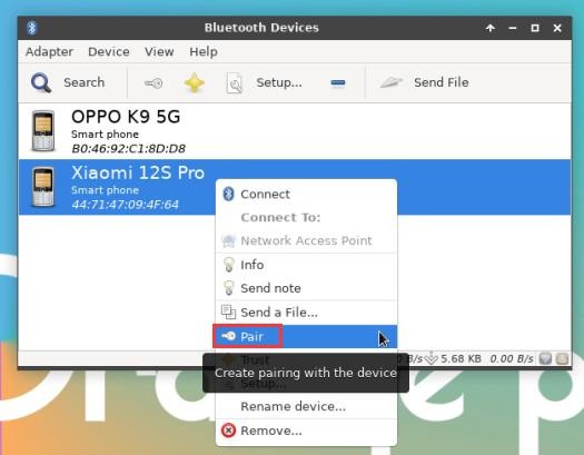
7) Then select the Bluetooth device you want to connect to, and then click the right button of the mouse to pop up the operation interface of the Bluetooth device, select Pair to start pairing, and the demonstration here is to pair with an Android phone
8) When pairing, a pairing confirmation box will pop up in the upper right corner of the desktop, just select Confirm to confirm, and the phone also needs to confirm at this time

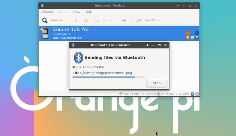
9) After pairing with the mobile phone, you can select the paired Bluetooth device, then right-click and select Send a File to start sending a picture to the mobile phone
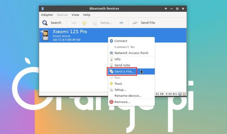
10) The interface for sending pictures is as follows
USB interface test
| The USB interface can be connected to a USB hub to expand the number of USB interfaces. |
Connect USB mouse or keyboard to test
1) Insert the USB interface keyboard into the USB interface of the Orange Pi development board
2) Connect the Orange Pi development board to the HDMI display
3) If the mouse or keyboard can operate normally, it means that the USB interface is working normally (the mouse can only be used in the desktop version of the system)
Connect USB storage device test
1) First insert the U disk or USB mobile hard disk into the USB interface of the Orange Pi development board
2) Execute the following command, if you can see the output of sdX, it means that the U disk is recognized successfully
|
orangepi@orangepi:~$ cat /proc/partitions | grep "sd*" |
3) Use the mount command to mount the U disk to /mnt, and then you can view the files in the U disk
| orangepi@orangepi:~$ sudo mount /dev/sda1 /mnt/ orangepi@orangepi:~$ ls /mnt/ |
The following command can be used to mount the U disk in exfat format on the Linux system
| orangepi@orangepi:~$ sudo apt-get install exfat-utils exfat-fuse orangepi@orangepi:~$ sudo mount -t exfat /dev/sda1 /mnt/ |
4) After mounting, you can view the capacity usage and mount point of the U disk through the df -h command
|
orangepi@orangepi:~$ df -h | grep "sd" |
USB wireless network card test
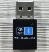
The usable USB wireless network cards that have been tested so far are as follows. Please test other types of USB wireless network cards by yourself. If they cannot be used, you need to transplant the corresponding USB wireless network card driver.
| serial number | model | |
| 1 | RTL8723BU Support 2.4G WIFI+BT4.0 |
|
| 2 | RTL8811 Support 2.4G +5G WIFI |

|
| 3 | RTL8821CU Support 2.4G +5G WIFI 支持 BT 4.2 |

|
1.RTL8723BU test
1) First insert the RTL8723BU wireless network card module into the USB interface of the development board
2) Then the linux system will automatically load the RTL8723BU bluetooth and WIFI-related kernel modules, through the lsmod command, you can see that the following kernel modules have been automatically loaded
orangepi@orangepi:~$ lsmod
|
3) Through the dmesg command, you can see the loading information of the RTL8723BU module
| orangepi@orangepi:~$ dmesg |
4) Then you can see the device node of RTL8723BU WIFI through the sudo ifconfig command. For the connection and test method of WIFI, please refer to the section of WIFI connection test, which will not be repeated here
| orangepi@orangepi:~$ sudo ifconfig wlx0013eff458ae wlx0013eff458ae: flags=4099<UP,BROADCAST,MULTICAST> mtu 1500 |
5) Then you can see the USB Bluetooth device through the hciconfig command
| orangepi@orangepi:~$ sudo apt update && sudo apt install bluez orangepi@orangepi:~$ hciconfig |
6) You can also see the bluetooth icon on the desktop. At this time, the bluetooth is not turned on, so a red x will be displayed

7) Click Turn Bluetooth On to turn on Bluetooth

8) The display after turning on Bluetooth is as follows

9) For the test method of Bluetooth, please refer to the section on Bluetooth usage, so I won’t go into details here
2.RTL8811 test
1) First insert the RTL8811 wireless network card module into the USB interface of the development board
2) Then the linux system will automatically load the kernel module related to RTL8811 WIFI, through the lsmod command, you can see that the following kernel module has been automatically loaded
orangepi@orangepi:~$ lsmod
|
3) Through the dmesg command, you can see the loading information of the RTL8811 module
| orangepi@orangepi:~$ dmesg [ 118.618194] usb 2-1: new high-speed USB device number 2 using ehci-platform |
4) Then, you can see the WIFI device node through the sudo ifconfig command. For the WIFI connection and test method, please refer to the WIFI connection test section, which will not be repeated here
| orangepi@orangepi:~$ sudo ifconfig wlx1cbfced9d260 wlx1cbfced9d260: flags=4099<UP,BROADCAST,MULTICAST> mtu 1500 |
3.RTL8821CU test
1) First insert the rtl8821cu wireless network card module into the usb interface of the development board
2) Then use the lsusb command to see the device information of the rtl8821cu usb wifi module, please make sure that the USB module is not in Driver CDROM Mode
| grep "Realtek" Bus 002 Device 003: ID 0bda:c820 Realtek Semiconductor Corp. 802.11ac NIC |
| grep "Realtek" Bus 002 Device 002: ID 0bda:1a2b Realtek Semiconductor Corp. RTL8188GU 802.11n WLAN Adapter (Driver CDROM Mode) If the USB WIFI module seen by the lsusb command is in Driver CDROM Mode, please unplug the USB WIFI module again. If not, please manually execute the following command to switch to the next mode: |
3) The linux system will automatically load the rtl8821cu bluetooth and wifi related kernel modules, through the lsmod command, you can see that the following kernel modules have been automatically loaded
orangepi@orangepi:~$ lsmod
|
4) Through the dmesg command, you can see the loading information of the rtl8821cu module
| orangepi@orangepi:~$ dmesg ...... |
5) Then you can see the device node of rtl8821cu wifi through the sudo ifconfig command. For the wifi connection and test method, please refer to the section of WIFI connection test, which will not be repeated here
| orangepi@orangepi:~$ sudo ifconfig wlx90de80521825 wlx90de80521825: flags=4099<UP,BROADCAST,MULTICAST> mtu 1500 |
6) Then you can see the USB Bluetooth device through the hciconfig command
| orangepi@orangepi:~$ sudo apt-get update && sudo apt-get install -y bluez orangepi@orangepi:~$ hciconfig |
7) You can also see the bluetooth icon on the desktop. At this time, the bluetooth is not turned on, so a red x will be displayed

8) Click Turn Bluetooth On to turn on Bluetooth

9) The display after turning on Bluetooth is as follows

10) For the test method of Bluetooth, please refer to the section on Bluetooth usage, so I won’t go into details here
USB camera test
1) First, you need to prepare a USB camera that supports UVC protocol as shown in the figure below or similar, and then insert the USB camera into the USB port of the Orange Pi development board

2) Through the v4l2-ctl command, you can see that the device node information of the USB camera is /dev/video0
| orangepi@orangepi:~$ v4l2-ctl --list-devices Q8 HD Webcam: Q8 HD Webcam (usb-fc880000.usb-1): |
| Note that the l in v4l2 is a lowercase letter l, not the number 1. In addition, the serial number of the video is not necessarily video0, please refer to what you actually see. |
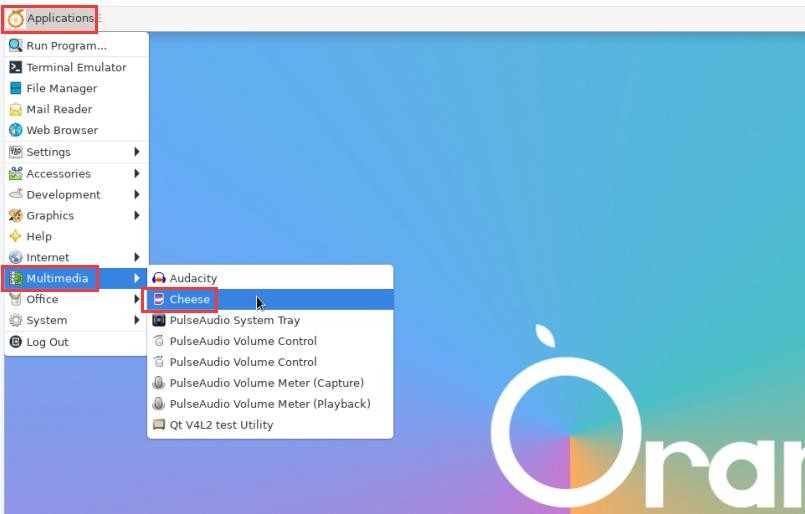
3) In the desktop system, Cheese can be used to directly open the USB camera. The method of opening Cheese is shown in the figure below.:
The interface after Cheese turns on the USB camera is shown in the figure below:

4) Method of using fswebcam to test USB camera
a. Install fswebcam
| orangepi@orangepi:~$ sudo apt update orangepi@orangepi:~$ sudo apt-get install -y fswebcam |
b. After installing fswebcam, you can use the following command to take pictures
a) -d option is used to specify the device node of the USB camera
b) --no-banner is used to remove the watermark of the photo
c) The -r option is used to specify the resolution of the photo
d) The -S option is used to set the number of previous frames to skip
e) ./image.jpg is used to set the name and path of the generated photo
| orangepi@orangepi:~$ sudo fswebcam -d /dev/video0 \ --no-banner -r 1280x720 -S 5 ./image.jpg |
c. In the server version of the linux system, you can use the scp command to transfer the taken pictures to the Ubuntu PC for image viewing after taking pictures
| orangepi@orangepi:~$ scp image.jpg test@192.168.1.55:/home/test( Modify the IP address and path according to the actual situation) |
d. In the desktop version of the linux system, you can directly view the captured pictures through the HDMI display
Testing audio methods on desktop systems
1) First open the file manager

2) Then find the following file (if there is no audio file in the system, you can upload an audio file to the system yourself)

3) Then select the audio.wav file, right click and select open with vlc to start playing

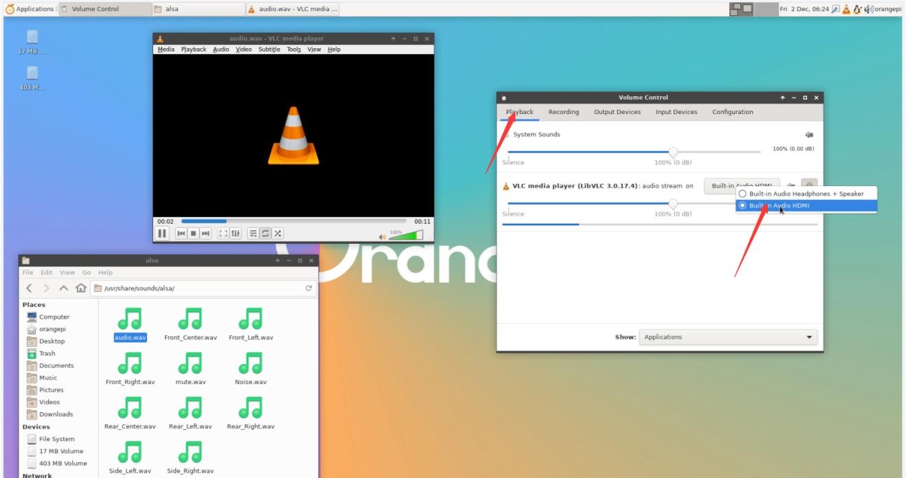
4) How to switch between different audio devices such as HDMI playback and headphone playback
a. First open the volume control interface

b. When playing audio, the audio device options that the playback software can use will be displayed in Playback, as shown in the figure below, where you can set which audio device to play to
The method of using commands to play audio
1.Headphone interface playback audio test
1) First insert the earphone into the earphone jack of the development board

2) Then you can use the aplay -l command to view the sound card devices supported by the linux system. From the output below, we can see that card 2 is the sound card device of es8388, that is, the sound card device of the headset
orangepi@orangepi:~$ aplay -l
card 0: rockchipdp0 [rockchip-dp0], device 0: rockchip-dp0 spdif-hifi-0 [rockchip-dp0 spdif-hifi-0] Subdevices: 1/1 |
3) Then use the aplay command to play the audio file that comes with the system. If the earphone can hear the sound, it means that the hardware can be used normally.
| rangepi@orangepi:~$ aplay -D hw:2,0 /usr/share/sounds/alsa/audio.wav Playing WAVE 'audio.wav' : Signed 16 bit Little Endian, Rate 44100 Hz, Stereo |
2.HDMI audio playback test
1) First use the HDMI to HDMI cable to connect the Orange Pi development board to the TV (other HDMI monitors need to ensure that they can play audio)
2) Then check the serial number of the HDMI sound card. From the output below, you can know that the HDMI sound card is card 1
orangepi@orangepi:~$ aplay -l
card 0: rockchipdp0 [rockchip-dp0], device 0: rockchip-dp0 spdif-hifi-0 [rockchip-dp0 spdif-hifi-0] Subdevices: 1/1 |
3) Then use the aplay command to play the audio file that comes with the system. If the HDMI monitor or TV can hear the sound, it means that the hardware can be used normally
| orangepi@orangepi:~$ aplay -D hw:1,0 /usr/share/sounds/alsa/audio.wav |
Method of using commands to test recording
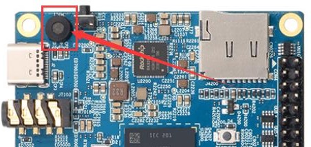
1) There is an onboard MIC on the development board, the location is as follows:
2) Running the test_record.sh main command will record a piece of audio through the onboard MIC, and then play it to HDMI and headphones
| orangepi@orangepi:~$ test_record.sh main Start recording: /tmp/test.wav |
3) In addition to the onboard MIC, we can also record audio through headphones with MIC function. After inserting the headset with MIC function into the development board, run the test_record.sh headset command to record a piece of audio through the headset, and then play it to HDMI and the headset.
| orangepi@orangepi:~$ test_record.sh headset Start recording: /tmp/test.wav |
26 Pin Interface Pin Description
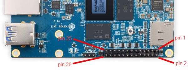
1) Please refer to the figure below for the order of the 26 pin interface pins on the Orange Pi 5 development board
2) The functions of the 26 pin interface pins on the Orange Pi 5 development board are shown in the table below
a. The following is the complete pin diagram of 26pin

b. The table below is the picture of the left half of the complete table above, so you can see it clearly

c. The table below is the picture of the right half of the complete table above, so you can see it clearly
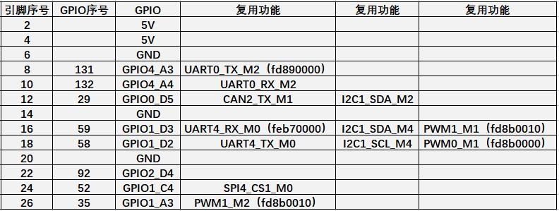
| The pwm in the above table has marked the base address of the corresponding register, which is useful when checking which pwmchip in /sys/class/pwm/ corresponds to which pwm pin in the 26pin header. |
3) There are a total of 17 GPIO ports in the 26pin interface, and the voltage of all GPIO ports is 3.3v
Instructions for the use of the android 12 system
How to use the use of wireless network card
1) At present, the USB wireless network card model that is adapted to the image is shown below:
| Chip model | Function | VID&PID | Adaptation |
| RTL8821CU | 2.4G +5G WIFI+BT 4.2 | 0bda:c820 | Only support wifi, Bluetooth needs to be adapted |
| RTL8723BU | 2.4G WIFI+BT4.0 | 0bda:b720 | Only support wifi, Bluetooth needs to be adapted |
| RTL8811CU | 2.4G +5G WIFI | 0bda:c811 | Only WIFI function, supported |
2) The picture of the above three USB wireless network cards is shown below:
a. The picture of the RTL8821CU USB wireless network card module is shown below:

b. The pictures of the RTL8723BU USB wireless network card module are shown below:
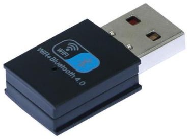
c. The picture of the RTL8811CU USB wireless network card module is shown below:
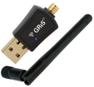
3) The test methods of the USB wireless network cards of the above 3 models are the same. First, insert the USB network card into the USB interface of the development board, and then enter Setting

4) Then choose Network & internet

5) Then choose Internet

6) Then turn on the Wi-Fi switch

7) If everything is normal after opening the Wi-Fi, you can scan to the nearby Wi-Fi hotspot

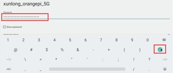
8) Then select the Wi-Fi you want to connect, and you will pop up the password input interface shown in the figure below

9) Then use the keyboard to enter the corresponding password of the wi-fi, and then use the mouse to click the Enter button in the virtual keyboard to start connecting Wi-Fi
10) The display after the Wi-Fi connection is successful as shown in the figure below:

26pin GPIO port test
1) First click the Wiringop icon to open the Wiringop App

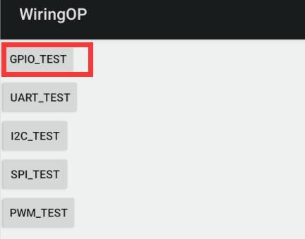
2) The main interface of the Wiringop app is displayed as shown in the figure below, and then click the GPIO_TEST button to open the GPIO test interface
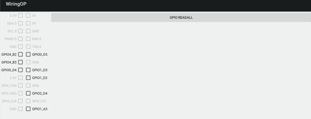
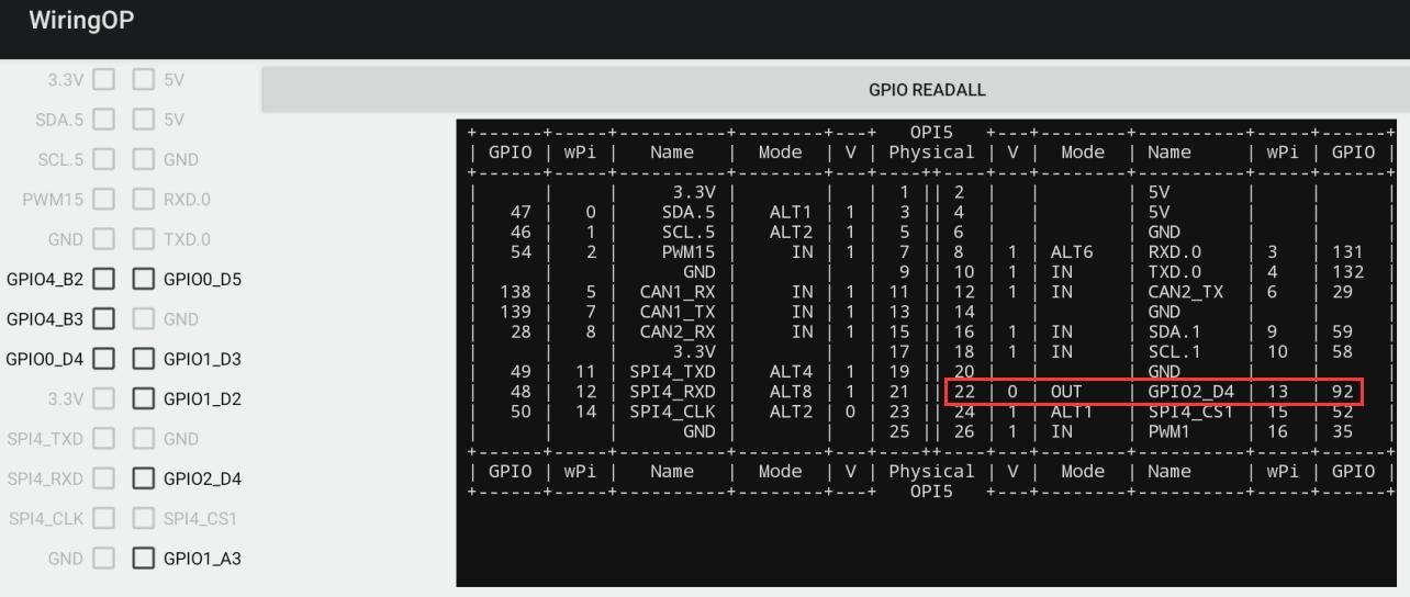
3) The GPIO test interface is shown in the figure below. The two rows of the CheckBox button on the left and the 26PIN pin are one -to -one relationship. When checking the CheckBox button, the corresponding pin will be set to OUT mode, the pin level settings will be set. For high levels, when the check -up is canceled, the pin level is set to a low level; when clicking the GPIO READALL button on the right, you can get the WPI, GPIO mode, pin level information, etc.
4) Then click the GPIO READALL button, and the output information is shown in the figure below
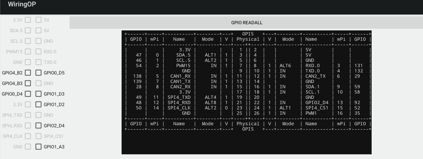
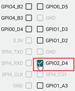
5) Taking the high and low level of the GPIO2_D4 as an example, click the CheckBox button in the figure below. When the button is selected, the GPIO2_D4 is set to a high level. After setting, you can use the value of the voltage of the pins by the multimeter. If it is 3.3v, Explain that setting high -electricity is successful
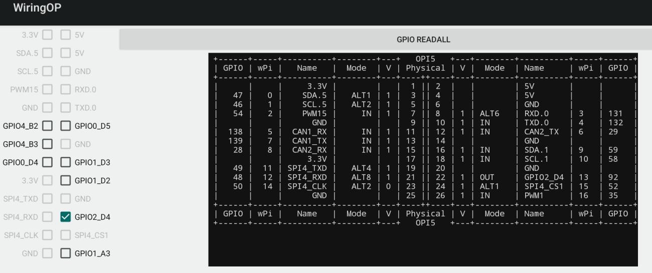
6) Then click the GPIO READALL button to see that the pins mode of the current GPIO2_D4 is OUT, and the pin level is high level
7) Click the CheckBox button in the figure below to cancel the check status. The GPIO2_D4 pin is set to a low level. After setting, you can use the value of the voltage of the multimeter to measure the pins.If it is 0v, the low -power flat is set.
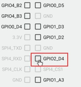
8) Then click the GPIO READALL button to see that the pins mode of the current GPIO2_D4 is OUT, and the pin level is low
26pin UART test
1) In Android default, the UART0 serial port is only opened. The position of UART0 at 26pin is shown in the figure below. The corresponding device node is/dev/ttys0

2) First click the WiringOP icon to open the Wiringop App

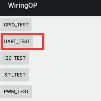
3) The main interface of the WiringOP APP is displayed as shown in the figure below, and then click the UART_TEST button to open the UART test interface
4) The serial test interface of the APP is shown in the figure below

5) Then enter the baud rate you want to set in the editing box, and then click the OPEN button to open the /dev/ttyS0 node. After successful, the OPEN button becomes an optional state.The CLOSE button and the SEND button become an optional state

6) Then use the DuPont line to shorte the RXD and TXD pin of uart0

7) Then you can enter a section of characters in the editing box below, click the SEND button to start sending
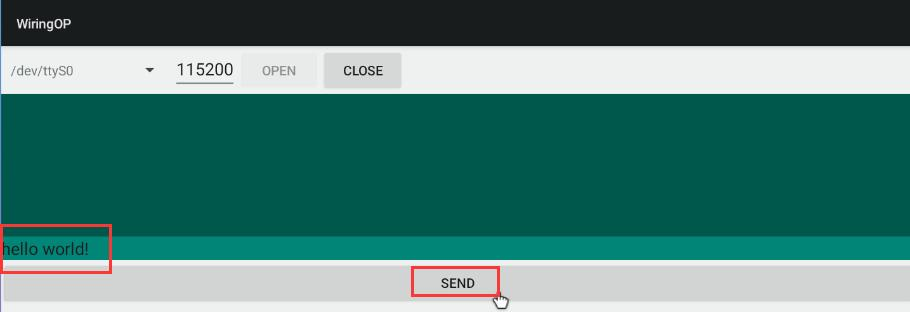
8) If everything is normal, the receiving string will be displayed in the receiving box

26pin's PWM test
1) Android only opened PWM15 by default. The corresponding pins are at the position of 26Pin.

2) First click theWiringOP icon to open the Wiringop App

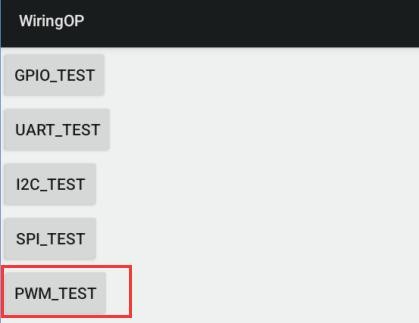
3) Then click the PWM_TEST button to enter the PWM test interface at the main interface of WiringOP
4) The corresponding address corresponding to the PWM15 is febf0030. The right side of PWMCHIP0 is exactly the febf0030.pwm. If the displayed base address is wrong, please click the drop -down option to select other PWMCHIP until the febf0030 is displayed on the right.

5) Then confirm the PWM cycle. The default configuration is 50000ns, and the PWM frequency is 20KHz. You can modify it by yourself.Click on the button to export PWM15

6) Then drag the drag below to change the PWM duty ratio, and then check the enable to output PWM


26pin's SPI test
1) From the schematic diagram of the 26pin interface, the SPI available for Orange Pi 5 is spi4

2) Here is the w25q64 module to test the SPI interface, and first access the w25q64 device at the SPI4 interface.
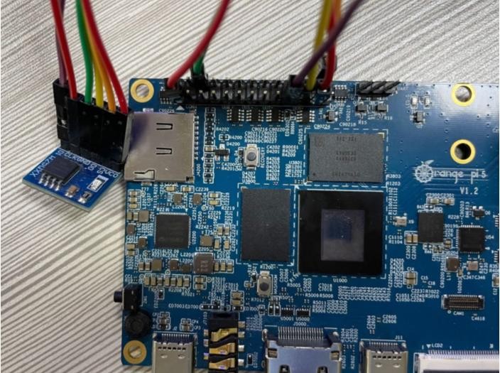
3) Then click the WiringOP icon to open the WiringOP APP

4) The main interface of the WiringOP APP shows as shown in the figure below, click the SPI_TEST button to open the SPI test interface
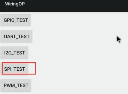
5) Then click the OPEN button to initialize SPI
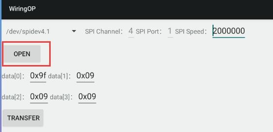
6) Then fill in bytes that need to be sent, such as reading the ID information of W25Q64, fill in the address 0x9F in data [0], and then click the TRANSFER button
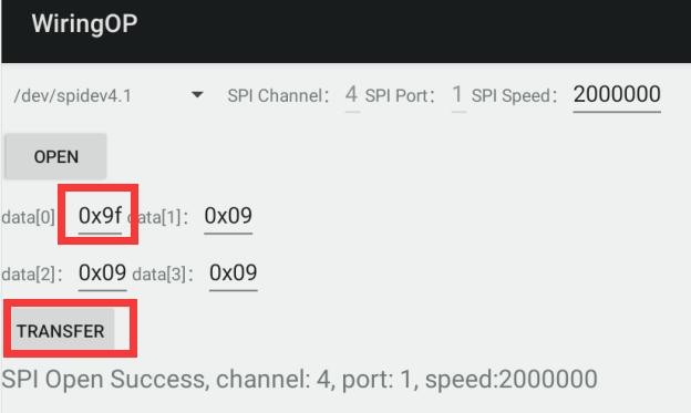
7) The last app will display the ID information read
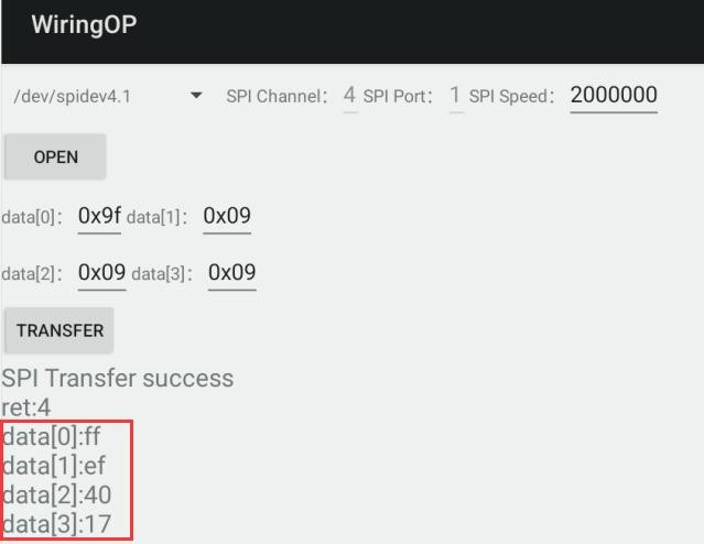
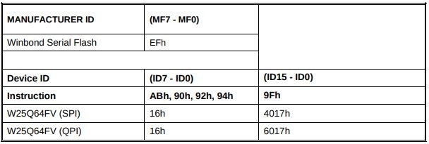
8) The MANUFACTURER ID of the w25q64 module is EFh, the Device ID is 4017h, and the value read above is corresponding (H represents hexadecimal)
